

Page 1
KJ JEEP COMBINATION BULL BAR
PRODUCT NUMBER FITTING KIT NUMBER
3450120 6171962
WARNING
FOR VEHICLES EQUIPPED WITH SRS AIRBAG
WHEN INSTALLED IN ACCORDANCE WITH THESE INSTRUCTIONS, THE FRONT
PROTECTION BAR DOES NOT AFFECT OPERATION OF THE SRS AIRBAG.
TAKE NOTE OF THE FOLLOWING:
• THIS PRODUCT MUST BE INSTALLED EXACTLY AS PER THESE INSTRUCTIONS
USING ONLY THE HARDWARE SUPPLIED.
• DO NOT USE THIS PRODUCT FOR ANY VEHICLE MAKE OR MODEL, OTHER THAN
THOSE SPECIFIED BY ARB.
• DO NOT REMOVE LABELS FROM THIS BULL BAR.
• THIS PRODUCT OR ITS FIXING MUST NOT BE MODIFIED IN ANY WAY.
29/8/05 Page 1 of 12 3783172
If you have any queries regarding the installation of this product please contact the distributor from whom it was purchased, or alternatively the ARB office in your state.
(08) 9244 3553
WA:
Head Office – ARB Corporation Ltd VIC: 42-44 Garden Street, Kilsyth, Victoria, 3137 Tel: (03) 9761 6622 Fax: (03) 9761 6807
(02) 9821 3633
NSW:
(02) 6280 7475
ACT:
(08) 8244 5001
SA:
(07) 3872 3872
QLD:
(08) 8947 2262
NT:
(03) 6331 4190
TAS:
Page 2

USE PART No QTY DESCRIPTION
IMPACT ABSORBER 6151232 10 BOLT M10 x 30mm
MOUNTING SYSTEM 4581040 10 WASHER FLAT M10
4581048 10 WASHER SPRING M10
4601044 2 CHANNEL CAPTIVE NUT (INSIDE CHASSIS RAILS)
4601045 2 CHANNEL CAPTIVE NUT (INSIDE CROSSMEMBER)
3756772 1 MOUNTING SYSTEM
BULL BAR TO 6151232 6 BOLT M10 x 30mm
IMPACT ABSORBERS 4581048 6 WASHER SPRING M10
4581040 8 WASHER FLAT M10
6151026 2 NUT M10
CONTROL BOX BRACKET 6151021 2 BOLT M8 x 20mm
4581044 2 WASHER FLAT M8
3751564 1 CONTROL BOX BRACKET
6151132 2 NUT FLANGE M8
NUMBER PLATE BRACKET 6151180 2 BOLT M6 x 20mm (BRACKET TO BAR)
6151046 4 WASHER FLAT M6 x 13mm
6151128 4 NUT FLANGE M6
6151017 2 BOLT M6 x 16mm (NUMBER PLATE TO BRACKET)
3751370 1 NUMBER PLATE BRACKET
INDICATORS TO BULL BAR 6821151R 1 INDICATOR KIT, RHS
6821151L 1 INDICATOR KIT, LHS
6821116 4 NYLON PLUG
6151308 4 SCREW, SELF TAPPING
6821152 2 WIRING LOOM
180701 6 SCOTCH LOCK
WINCH 4581040 4 WASHER FLAT 3/8” x 1"
(8000/9000/9500 LB) 6151074 2 BOLT 1 ¾” x 3/8” UNC
180302 10 CABLE TIES
6191005 1 EXTRUSION RUBBER
WINCH PAN COVER 6521031 1 PANEL WINCH COVER
6151256 2 SCREW BUTTON HEAD M6 x 16mm
6151128 2 NUT FLANGE M6
AIR DEFLECTOR 6522656 1 AIR DEFLECTOR
6151017 4 BOLT M6 X 16mm
6151128 4 NUT M6 - FLANGE
4581072 4 WASHER FLAT M6 x 20mm
WASHER BOTTLE COVER 6522655R 1 PANEL WING KJ JEEP 05
6522655L 1 PANEL WING KJ JEEP 05
6151300 6 CAGE NUT M6 (3mm PLATE)
6151180 14 BOLT M6 x 20
4581072 14 WASHER FLAT M6 x 20mm
4581036 6 WASHER SPRING ¼”
FOG LIGHT HOUSING / 6151300 4 CAGE NUT, M6 (3mm PLATE)
APERTURE COVER 6151180 4 BOLT M6 x 20
FITMENT 4581072 4 WASHER FLAT M6 (20 OD)
4581036 4 WASHER SPRING ¼”
3756777 2 BRKT FOG MNT KJ JEEP 05
3756778R 1 BRKT COVER MNT (RH) KJ JEEP 05
3756778L 1 BRKT COVER MNT (LH) KJ JEEP 05
6821184 1 3mm RED WIRE (1.3m LONG)
180701 8 SCOTCH LOCK
3162468 2 INSERT FOG INDICATOR SURROUND
6151317 8 SCREW 8-18 x 5/8 PAN HEAD
WHEEL LINER 6151017 4 BOLT M6 x 16mm
TO BAR 4581072 4 WASHER FLAT M6 x 20mm
6151128 4 NUT FLANGE M6
6151128 8 NUT FLANGE M6
29/8/05 Page 2 of 12 3783172
Page 3
TOOLS REQUIRED.
BASIC TOOL KIT, KEY HOLE SAW, TORX KEY T-15
ASSEMBLY SEQUENCE FOR BULL BAR INSTALLATION.
PLEASE READ AND UNDERSTAND FITTING INSTRUCTIONS BEFORE
ATTEMPTING TO FIT BAR TO VEHICLE
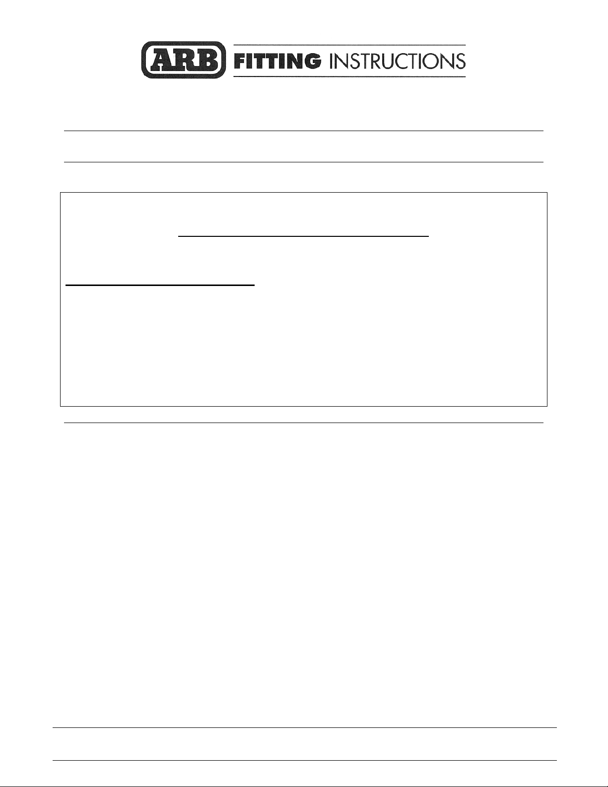
1. Remove grille from vehicle using torx
keys.
2. Remove bumper from vehicle and
disconnect the turn signal lights. If the
vehicle is fitted with fog lamps, as
shown in the adjacent photo, remove
the fog lamps.
3. Be careful when removing bumper
from the flares, as the plastic clips are
awkward to undo.
4. Remove the turn signal lights.
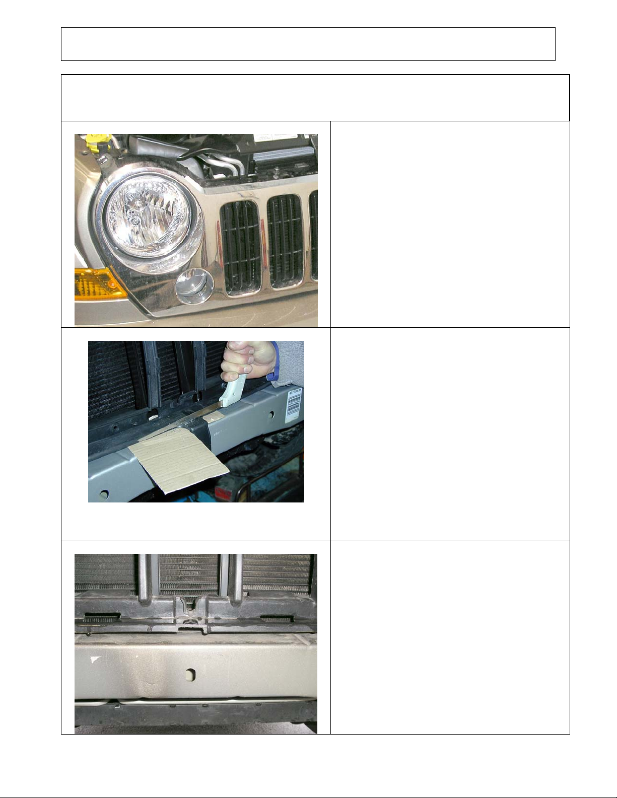
5. When bumper is removed, cut the
lower plastic lug from grille panel to
enable bull bar mounting system to bolt
up against vehicle cross member. Place
either thick cardboard or plywood
either side of lug to prevent paint
damage.
Remove tow hook and crush
cans from vehicle.
29/8/05 Page 3 of 12 3783172
Keep the fasteners used on the original
bumper as some will be re-used on the new
bull-bar.
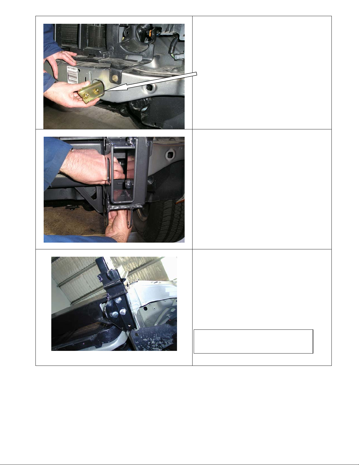
6. This is how it must look when it has
been cut.
Page 4
7. To fit mounting system to vehicle, fit
captive nut channel in through front
apertures in vehicle cross member on both
sides.
(Notch in channel must face front of vehicle)
8. When both channels are inside of cross
member, using your finger, align with holes
underneath of chassis rails.
9. Fit mounting system to front cross member
of vehicle and centralized sideways.
10. Fit 10mm hardware to the two most
forward holes in lower brackets, to both sides
of vehicle, making sure mounting system is
hard up against vehicle cross member, tighten
firmly.
Photo shows underside of mounting
system on LHS of vehicle.
29/8/05 Page 4 of 12 3783172
Page 5

11. Using 10mm drill bit, drill out holes in
centre of slots in front of cross member.
12. Once holes have been drilled, fit captive nut
channels through lower aperture in vehicle
cross member.
13. Secure using 10mm hardware and tighten
firmly making sure mounting system is hard
against vehicle cross member.
NB. When step 14 is finished, slacken off
bolt tension to enable sideways movement if
needed when bar is fitted.
29/8/05 Page 5 of 12 3783172
Page 6

14. When front bolts are tight, loosen off lower
bolts in chassis brackets. Using a 10mm drill
bit, drill out the most rearward hole in lower
chassis bracket being careful not to drill too
far into captive nut channel. When holes have
been drilled, realign the rear hole with rear
nut in captive nut channel, and secure using
10mm hardware, then lightly tighten all bolts
in lower chassis brackets.
MOUNTING SYSTEM MUST BE ABLE TO
BE MOVED SIDEWAYS.
15. If the vehicle is fitted with fog lights in the
grill, as shown in diagram 1, the fog loom will
need to be extended. First, cut the 1.3m red
wire, supplied in the kit, into four equal
lengths (i.e. 325mm each) and then cut the
plug off the vehicle’s fog loom. Use the four
pieces of wire just cut together with the scotch
locks to lengthen the vehicle’s fog loom and reconnect the plugs. Once this task has been
completed for both the LH & RH fog lights,
refit the grill to the vehicle and allow the fog
looms to hang out through the fog apertures.
16. To fit the turn signal / park light loom first
Vehicle Park Loom
unplug the loom going into the park light in
the headlamp. This is the lower small plug on
the lower half of the head light. Disconnect
this clip by first pulling the red lever back then
push the black tab (behind the red lever) down
and pull the clip apart. Remove the plastic
sleeve from the loom supplied and then use a
plastic scotch lock to connect red wire
(supplied loom) to the yellow / black wire
(passenger side) or the yellow / green wire
(drivers side) of the vehicle park light loom.
Once this connection has been made reconnect
vehicle’s loom into the park light and feed the
new loom behind and below the headlight.
Next use scotch locks to connect the remaining
two wires to the vehicle’s blinker loom.
Summary of Wire Connections
SIGNAL
PARK LAMP RED GREEN /
EARTH BLACK BLACK BLACK
INDICATOR GREEN RED RED
29/8/05 Page 6 of 12 3783172
HARNESS
VEHICLE PARK LAMP FUNCTION TURN
RIGHT LEFT
YELLOW
VEHICLE INDICATOR
RIGHT LEFT
YELLOW /
BLACK
Page 7

17. Fit the M6 cage nuts to the bull-bar to
mount the fog lights.
Fit the nylon plugs, used to mount the
indicator / clearance lamps.
Fit the M6 cage nuts to mount the washer
bottle / horn stone guards.
18. Remove the fastening screws and nuts
supplied with the turn signal/clearance lamps
and replace these with the four screws
provided in the kit. Fasten the lamps to the
bar as shown.
IMPORTANT
The turn signal is to the inside of the bar.
19. If bar is to have a winch fitted, follow the
next steps.
20. Fit number plate bracket to bar using
6mm hardware. (20mm x 6mm bolts) Fit
number plate to number plate bracket using
6mm hardware when bar is fitted to vehicle.
21. Fit control box bracket to bar using 8mm
hardware.
VIEW OF THE CENTRE OF BAR
22. Drill 12mm holes under existing holes
25mm lower down the same pitch as existing
holes, these will be the holes used to bolt to
bar.
NEW HOLES
29/8/05 Page 7 of 12 3783172
Page 8

23. To fit winch into bar you must pack winch
up on a bench to enable you to lower bar down
on winch.
24. Line up top holes first and secure using
3/8” hardware (1 ½”” x 3/8”bolts) flat and
spring washers.
25. Place roller fairlead over lower holes and
again secure using 3/8” hardware (1 ¾”x 3/8”
bolts) flat and spring washers. When all bolts
are fitted tighten firmly.
26. Fit control box to control box bracket
using original ¼” nuts from control box and
connect power cables to winch motor as per
winch instructions.
27. Cable tie power cables to bar keeping
cables clear from all moving parts.
Optional driving light fitted.
( Viewed from rear of bar )
Fasten control box earth to
winch tie rods.
29/8/05 Page 8 of 12 3783172
Page 9

28. Cable tie power leads to battery, to the left
side of the bar keeping clear of all moving
parts.
(Viewed from rear of bar)
29. Slide bar onto vehicle mounting system
and secure using 10mm hardware. Place rags
between the bar and the vehicle’s grill to avoid
the grill being scratched.
Prior to bolting the bar in place ensure the
vehicles mudguards are tucked inside the
wings as shown on the adjacent photo.
Align bar with vehicle grille and flares, and
tighten bolts using socket, extension and uni
joint through fog light aperture in bar. The
vertical gap between the vehicle’s flares and
the top of the bull-bars wings should be 16mm.
Lastly retighten the mounting system bolts
when bar has been centralized sideways.
30. Once the bar is in position, fasten the
wheel liners to the bar using the M6 hardware.
Drill through the wheel liner using the lower
wing hole and fasten.
31. Once bar is secured to vehicle, using holes
in locking plates as a template, drill 10mm
holes through lower section of bar and bolt up
using 10mm hardware.
29/8/05 Page 9 of 12 3783172
Page 10

32. If bar is going to be a non-winch bar, fit
number plate directly to front of bar using
6mm hardware.
33. To fit cover plate on top of bar winch cutout, fit rubber extrusion around top cover
panel, trim to size and bolt to top of bar using
M6 button head stainless steel screws and M6
flange nuts.
34. If fitting fog lights removed at step 2,
fasten the fog lights to the brackets provided
as shown in the adjacent photo.
The black plastic fastener was taken off the
original bumper and re-used here.
Alternatively, if no fog lights are being fitted to
the bar, assemble the aperture covers to the
aperture cover brackets using the self-tapping
screws provided.
35. Fit the fog lights to the bull-bar, or the
aperture covers, with the M6 hardware. Next
connect the fog lights and the blinker /
clearance lamps to the looms fitted at steps 15
& 16.
29/8/05 Page 10 of 12 3783172
Page 11

36. Fit washer bottle / horn guards to bar &
vehicle using 6mm hardware.
M6x20 bolts, M6 flat washers, M6 flange nuts
M6x20 bolts, M6 spring washers, M6 flat
washers
M6x20 bolts, M6 flat washers, M6 flange nuts
37. Next step is to trim the plastic inner
guards that hang down past the bar.
Cut plastic level with the bottom of bar wing
section to washer bottle guard.
Bar wing section
29/8/05 Page 11 of 12 3783172
Page 12

38. Fitting of AIR DEFLECTOR to underside
of bar.
39. Fit rear of air deflector to vehicle lower
cross member using original screws and front
to bar using 6mm hardware. When all
hardware is fitted, tighten firmly.
The two middle screws were removed
elsewhere with the bumper and will be used
here. These screws will be self-thread cutting
as required.
40. Position for Hi Lift jacking point.
29/8/05 Page 12 of 12 3783172
 Loading...