

Page 1

23 1 01
Page 1 of 16
3783013
If you have any queries regarding the installation of this product please contact the distributor from whom it was purchased, or alternatively the ARB office in your state.
Head Office – ARB Corporation Ltd VIC: 42-44 Garden Street, Kilsyth, Victoria, 3137 Tel: (03) 9761 6622 Fax: (03) 9761 6807
WA: (08) 9244 3553 NSW: (02) 9821 3633 ACT: (02) 6280 7475 SA: (08) 8244 5001 QLD: (07) 3872 3872 NT: (08) 8947 2262 TAS: (03) 6331 4190
KJ JEEP COMBINATION BULL BAR
PRODUCT NUMBER FITTING KIT NUMBER
3450110 6171745
WARNING
FOR VEHICLES EQUIPPED WITH SRS AIRBAG
WHEN INSTALLED IN ACCORDANCE WITH THESE INSTRUCTIONS, THE FRONT
PROTECTION BAR DOES NOT AFFECT OPERATION OF THE SRS AIRBAG.
TAKE NOTE OF THE FOLLOWING:
• THIS PRODUCT MUST BE INSTALLED EXACTLY AS PER THESE INSTRUCTIONS
USING ONLY THE HARDWARE SUPPLIED.
• DO NOT USE THIS PRODUCT FOR ANY VEHICLE MAKE OR MODEL, OTHER THAN
THOSE SPECIFIED BY ARB.
• DO NOT REMOVE LABELS FROM THIS BULL BAR.
• THIS PRODUCT OR ITS FIXING MUST NOT BE MODIFIED IN ANY WAY.
Page 2

31 10 02
Page 2 of 16
3783013
USE
PART No
QTY
DESCRIPTION
6151232
10
BOLT M10 x 30mm
IMPACT ABSORBER
4581040
10
WASHER FLAT M10
MOUNTING SYSTEM
4581048
10
WASHER SPRING M10
4601044
2
CHANNEL CAPTIVE NUT (INSIDE CHASSIS RAILS)
4601045
2
CHANNEL CAPTIVE NUT (INSIDE CROSSMEMBER)
3756449
1
MOUNTING SYSTEM
BULL BAR TO
6151232
6
BOLT M10 x 30mm
IMPACT ABSORBERS
4581048
6
WASHER SPRING M10
4581040
8
WASHER FLAT M10
6151026
2
NUT M10
6151021
2
BOLT M8 x 20mm
CONTROL BOX BRACKET
4581044
2
WASHER FLAT M8
3751564
1
CONTROL BOX BRACKET
6151132
2
NUT FLANGE M8
NUMBER PLATE BRACKET
6151080
2
BOLT M6 x 20mm (BRACKET TO BAR)
6151046
4
WASHER FLAT M6 x 13mm
6151128
4
NUT FLANGE M6
6151017
2
BOLT M6 x 16mm (NUMBER PLATE TO BRACKET)
3751370
1
NUMBER PLATE BRACKET
TO BOLT INDICATORS TO BAR
6151126
2
BOLT M4 x 30mm
4581037
2
WASHER FLAT M4
5848283
2
WASHER PACKER NYLON
6151127
2
NUT NYLOC M4
8-9000lb WINCH
4581040
4
WASHER FLAT 3/8” x 1"
6151074
2
BOLT 1 ¾” x 3/8” UNC
180302
10
CABLE TIES
6191007
1
EXTRUSION RUBBER
WINCH PAN COVER
6521031
1
PANEL WINCH COVER
6151256
2
SCREW BUTTON HEAD M6 x 16mm
6151128
2
NUT FLANGE M6
AIR DEFLECTOR
3314463
1
AIR DEFLECTOR
6151017
4
BOLT M6 X 16mm
6151128
4
NUT M6 - FLANGE
4581072
4
WASHER FLAT M6 x 20mm
WASHER BOTTLE COVER
3314462
1
WASHER BOTTLE COVER
3756446
1
BRACKET COVER
6151022
2
BOLT M8 x 25mm
4581044
2
WASHER FLAT M8
6151132
2
NUT FLANGE M8
6151017
5
BOLT M6 x 16mm
4581072
3
WASHER FLAT M6 x 20mm
6151046
2
WASHER FLAT M6 x 13mm
6151128
5
NUT FLANGE M6
FLARE MOULDING
6191009
1
FLARE MOULDING
FOG LIGHT HOUSING
3162457
1
PLASTIC HOUSING RHS
AND FITMENT
3162456
1
PLASTIC HOUSING LHS
4581040
4
WASHER
INNER GUARD TO BAR
6151017
2
BOLT M6 x 16mm
4581072
2
WASHER FLAT M6 x 20mm
6151128
2
NUT FLANGE M6
TOOLS REQUIRED.
BASIC TOOL KIT, KEY HOLE SAW, TORX KEY T-15
Page 3

31 10 02
Page 3 of 16
3783013
ASSEMBLY SEQUENCE FOR BULL BAR INSTALLATION.
PLEASE READ AND UNDERSTAND FITTING INSTRUCTIONS BEFORE
ATTEMPTING TO FIT BAR TO VEHICLE
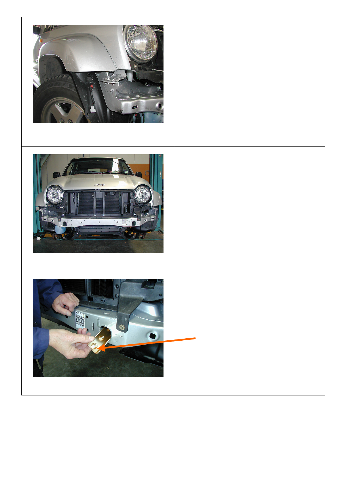
1. Remove grille from vehicle using torx
keys.
2. Remove bumper from vehicle and
remove all lights and the wiring loom
from bumper.
3. Be careful when removing bumper from
the flares as the plastic clips are
awkward to undo.
4. When bumper is removed, cut the lower
plastic lug from grille panel to enable
bull bar mounting system to bolt up
against vehicle crossmember. Place either
thick cardboard or plywood either side of
lug to prevent paint damage.
Remove tow hook and crush cans
from vehicle
5. This is how it must look when it has been
cut.
Page 4

31 10 02
Page 4 of 16
3783013
6. Cut the lower section off the vehicle
flares.
7. Mark a datum point by drawing a
horizontal line under the rivet inside the
inner guard. (Photo shows RHS of
vehicle)
8. Mark a second datum point where the
pencil is pointing, then using masking
tape join the two datum points together
making sure you have a level line.
9. Using a key hole saw, carefully cut below
the tape line.
Page 5
31 10 02
Page 5 of 16
3783013
10. Photo shows a finished cut flare.
11. The vehicle is now ready to fit mounting
system and bar.
(Grille and bumper removed, flares cut and
grille lug cut.)
12. To fit mounting system to vehicle, fit
captive nut channel in through front
apertures in vehicle crossmember on both
sides.
(Notch in channel must face front of vehicle)
Page 6

31 10 02
Page 6 of 16
3783013
13. When both channels are inside of
crossmember, using your finger, align with
holes underneath of chassis rails.
14. Fit mounting system to front crossmember of
vehicle and centralized sideways.
15. Fit 10mm hardware to the two most forward
holes in lower brackets, to both sides of
vehicle, making sure mounting system is
hard up against vehicle crossmember,
tighten firmly.
16. Using 10mm drill bit, drill out holes in centre
of slots in front of crossmember.
Photo shows underside of mounting
system on LHS of vehicle.
Page 7

31 10 02
Page 7 of 16
3783013
17. Once holes have been drilled, fit captive nut
channels through lower aperture in vehicle
crossmember.
18. Secure using 10mm hardware and tighten
firmly making sure mounting system is hard
against vehicle crossmember.
NB. When step 19 is finished, slacken off
bolt tension to enable sideways movement if
needed when bar is fitted.
19. When front bolts are tighten, loosen off lower
bolts in chassis brackets. Using a 10mm drill
bit, drill out the most rearward hole in lower
chassis bracket being careful not to drill too
far into captive nut channel. When holes has
been drilled, realigned the rear hole with
rear nut in captive nut channel, and secure
using 10mm hardware, then lightly tighten
all bolts in lower chassis brackets.
MOUNTING SYSTEM MUST BE ABLE TO
BE MOVED SIDWAYS.
Page 8

31 10 02
Page 8 of 16
3783013
20. If bar is going to be a non winch bar, fit
number plate directly to front of bar using
6mm hardware.
21. To fit cover plate on top of bar winch cutout,
fit rubber extrusion around top cover panel,
trim to size and bolt to top of bar using M6
button head stainless steel screws and M6
flange nuts.
22. Indicator installation to bar , fit indicator
tang into slot of fog light bracket and under
outer bracket. Slide plastic packer between
bracket and indicator and fasten using 4mm
screw ,flat washer and 4mm nyloc nut.
PHOTO VEIWED FROM INSIDE OF BAR LHS
Page 9

31 10 02
Page 9 of 16
3783013
23. If bar is to have original fog lights fitted,
position light into the two lower holes in light
mounting bracket, place packer washer
over light locating boss and refit light screws
into all 3 holes, tighten firmly using torx key.
( If vehicle does not have fogs fitted, they can be
purchased. Part no. 05083895 - 05083896 and
screw kit to suit. )
24. Refit vehicle loom to mounting system using
cable ties and plug back into connector body.
25. If bar is to have a winch fitted, follow the
next steps.
26. Fit number plate bracket to bar using 6mm
hardware.( 20mm x 6mm bolts ) Fit number
plate to number plate bracket using 6mm
hardware when bar is fitted to vehicle.
27. Fit control box bracket to bar using 8mm
hardware.
VIEW OF THE CENTRE OF BAR
Page 10

31 10 02
Page 10 of 16
3783013
28. Drill 12mm holes under existing holes 25mm
lower down the same pitch as existing holes,
these will be the holes used to bolt to bar.
29. To fit winch into bar you must pack winch
up on a bench to enable you to lower bar
down on winch.
30. Line up top holes first and secure using 3/8”
hardware (1 ½”” x 3/8”bolts ) flat and spring
washers.
31. Place roller fairlead over lower holes and
again secure using 3/8” hardware ( 1 ¾”x
3/8” bolts ) flat and spring washers. When all
bolts are fitted tighten firmly.
NEW HOLES
Page 11

31 10 02
Page 11 of 16
3783013
32 . Fit control box to control box bracket using
original ¼” nuts from control box and
connect power cables to winch motor as per
winch instructions.
33. Cable tie power cables to bar keeping cables
clear from all moving parts.
Optional driving light fitted.
( Viewed from rear of bar )
34. Cable tie power leads to battery, to the left
side of the bar keeping clear of all moving
parts.
( Viewed from rear of bar )
Fasten control box earth to
winch tie rods.
Page 12

31 10 02
Page 12 of 16
3783013
35. Position bar in front of vehicle and connect
indicators, fog lights and fit winch cables
under grille into engine bay close to battery.
36. Slide bar onto vehicle mounting system and
secure using 10mm hardware. Align bar with
vehicle grille and flares, and tighten bolts
using socket, extension and uni joint
through fog light aperture in bar. Lastly
retighten mounting system bolts when bar
has been centralized sideways.
37. Once bar is secured to vehicle, using holes in
locking plates as a template, drill 10mm holes
through lower section of bar and bolt up
using 10mm hardware.
38. Fit washer bottle guard bracket to bar
mounting system using 8mm hardware.
.
Fit 6mm hardware to bracket
and guard
Finger tighten
Page 13

31 10 02
Page 13 of 16
3783013
39. Bolt washer bottle guard to lower bar wing
section using 6mm hardware. ( finger tighten
only )
40. On RHS of vehicle, using vice grips to hold
in place, drill a 6mm hole through washer
guard into under side of vehicle
crossmember and secure using 6mm
hardware. When all bolts are fitted, tighten
firmly. Cut plastic upward so you can tuck
plastic inner guard in behind washer
bottle guard.
41. Next step is to trim the plastic inner guards
that hang down passed the bar.
42. On the RHS of vehicle, tuck plastic inner
guard in behind bar wing section and secure
using 6mm hardware. Cut plastic level with
the bottom of bar wing section to washer
bottle guard.
Washer guard
Wing section
Bar wing section
Viewed from under vehicle
Page 14

31 10 02
Page 14 of 16
3783013
43. On the LHS of vehicle cut plastic inner
guard as per photo, tuck in behind bar wing,
secure to bar wing section using 6mm
hardware.
44. Fitting of AIR DEFLECTOR to underside of
bar.
45. Fit rear of air deflector to vehicle lower
crossmember using original screws and front
to bar using 6mm hardware. When all
hardware is fitted, tighten firmly.
46. When everything on bar is fitted and tighten,
the last part to fit if so desired, is the stick on
plastic molding that covers up where the
vehicle flare has been cut.
47. Molding in bolt kit is for both sides of
vehicle.
48. To fit molding to flare, cut molding on
matching angle of where flare meets guard,
remove backing tape and adhere to vehicle
about 3mm above the wing section of bar.
49. Cut off molding flush with wheel arch.
Photo of inside of LHS guard
New cut line of plastic inner guard
Photo of LHS of vehicle
Matching angle for molding
Page 15

31 10 02
Page 15 of 16
3783013
50. If no fog lights are not going to be fitted, fit
light surround to bar as is. If fog lights are
going to be fitted, cut out rear of surround using
a key hole saw and remove rough edges with a
file.
51. Fitting of fog light surround housings.
52. Apply a bead of silicon around the fog light
aperture, fit the surround into aperture and
hold to bar using masking tape until silicon
has set, then remove tape.
53. Position for Hi Lift jacking point.
Page 16

31 10 02
Page 16 of 16
3783013
PHOTO SHOWS COLOUR CODED BAR
 Loading...