

Page 1
20-5-98 Page 1 of 4 3782549
If you have any queries regarding the installation of this product please contact the distributor from whom it was purchased, or alternatively the ARB office in your state.
Head Office – ARB corporation Ltd VIC: 42-44 Garden Street, Kilsyth, Victoria, 3137 Tel: (03) 9761 6622 Fax: (03) 9761 6807
WA:(08) 9244 3553 NSW: (02) 9821 3633 ACT: (02) 6280 7475 SA: (08) 8244 5001 QLD: (07) 3872 3872 NT: (08) 8947 2262 TAS: (03) 6331 4190
JEEP CHEROKEE ARB WINCH BULL BAR 1997 ON No 3450080
WARNING
FOR VEHICLES EQUIPPED WITH SRS AIRBAG
WHEN INSTALLED IN ACCORDANCE WITH THESE INSTRUCTIONS, THE FRONT
PROTECTION BAR DOES NOT AFFECT OPERATION OF THE SRS AIRBAG.
TAKE NOTE OF THE FOLLOWING:
• THIS PRODUCT MUST BE INSTALLED EXACTLY AS PER THESE INSTRUCTIONS USING ONLY THE
HARDWARE SUPPLIED.
• DO NOT USE THIS PRODUCT FOR ANY VEHICLE MAKE OR MODEL, OTHER THAN THOSE SPECIFIED
BY ARB.
• DO NOT REMOVE LABELS FROM THIS BULL BAR.
• THIS PRODUCT OR ITS FIXING MUST NOT BE MODIFIED IN ANY WAY.
FITTING KIT No 6171262
USE
PART No
QTY
DESCRIPTION
CONTROL BOX BRACKET
3751564
1
BRACKET CONTROL BOX
TO BULL BAR
6151021
2
BOLT M8 X 1.25 X 20mm
6151132
2
NUT FLANGE M8 X 1.25
4581044
2
WASHER FLAT M8 X 17 X 1.2
WINCH TO BULL BAR
6151110
2
BOLT UNC 5/8 X 6” GRADE 8
6151140
2
NUT UNC 5/8 NYLOC
4581051
4
WASHER FLAT 5/8”
6151074
2
BOLT UNC 3/8 X 1 ¾” GR5
6821110
1
RUBBER GROMMET
BULL BAR TO CHASSIS
3193540
2
PLATE - CAPTIVE NUT ASSY
4581049
12
WASHER FLAT 1/2" X 1 1/8" X 12G
4581050
8
WASHER SPRING 1/2" X 1/8" X 1/8"
4581040
8
WASHER FLAT M10
4581048
2
WASHER SPRING M10
6151071
2
BOLT UNC 3/8 X 1”
6151100
8
BOLT UNC 1/2X11/2” CLASS 8
6151138
4
NUT UNC ½”
5846267
2
PACKER
No PLATE BRACKET,
3751485
1
BRKT NUMBER PLATE
NUMBER PLATE AND
6151017
8
BOLT M6 X 1.0 X 16mm
INNER GUARD
6151046
8
WASHER FLAT 6mmZP
6151128
8
NUT FLANGE M6 X 1.0
3500080
1
ARB INDICATOR KIT
Page 2
20-5-98 Page 2 of 4 3782549
TOOLS REQUIRED
Basic tool kit, drill and ½” drill bit
PROCEDURE
1. Place the bull bar onto a suitable stand.
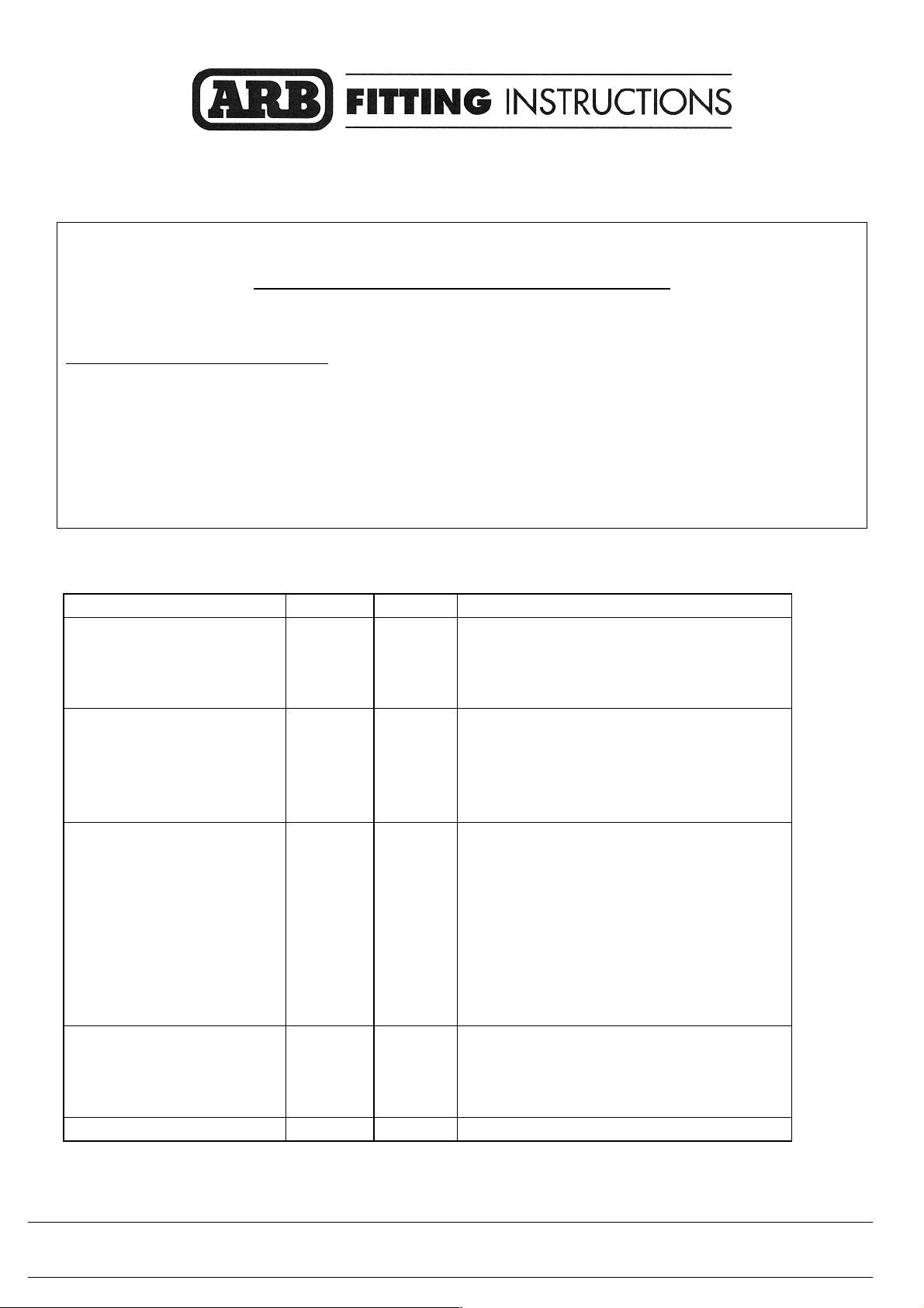
2. New mounting holes must be drilled in the roller fairlead in order to line up with the winch
mounting holes in the bull bar. (Refer to diagram 1.)
DIAGRAM 1
3. Remove the circlips which retain the side pins.
4. Remove the side pins and side rollers from the roller fairlead.
5. Position the roller fairlead hard up against the roller fairlead bracket on the bull bar.
6. From the rear of the bull bar, using the holes in the bull bar as a guide, mark out the new hole
position on the roller fairlead and drill out to ½”.
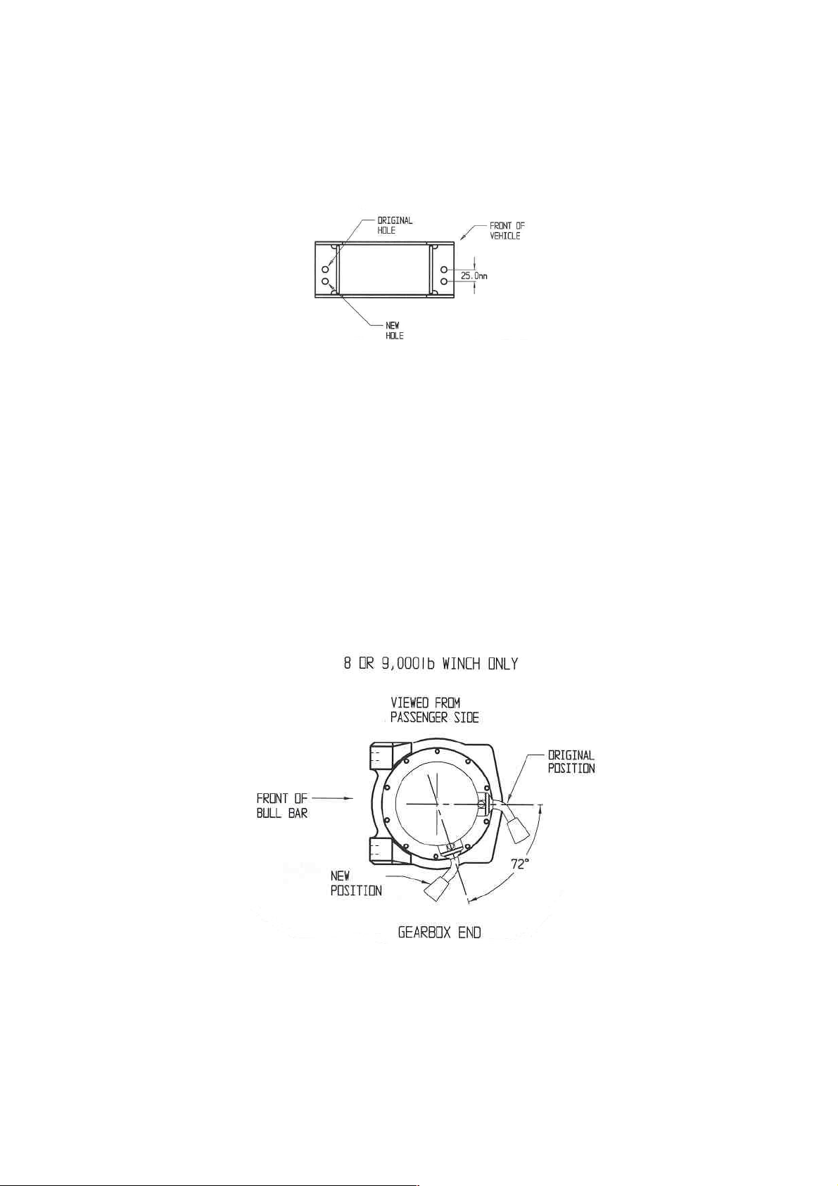
7. The winch clutch handle must be rotated to be easily accessible when fitted into the bull bar.
Remove all the Allen screws retaining the clutch and gearbox. Rotate this assembly clockwise so
the handle can be reached from the cut-out in the bull bar on the passenger side.
DIAGRAM 2
NOTE: Take care not to lift the assembly more than a couple of millimetres while rotating to the
desired position to avoid unmeshing the gears.
8. Refit all bolts and tighten.
9. Fit the rubber grommet to the hole in the top of the bull bar.
10. Mount the control box to the control box bracket using the original nuts on the control box.
Page 3

20-5-98 Page 3 of 4 3782549
11. Feed the control box cables down through the grommet to the winch motor.
12. Position the winch on the top of a 20 litre or 60 litre drum with the mounting holes facing upward.
13. Place the bull bar on top of the winch and align with the mounting holes. Using the bolts supplied
with the winch and the 3/8” washers in the ARB kit, fit and tighten the two upper bolts.
14. Place the roller fairlead in position over the two lower holes and fit two 3/8” x 1 ¾” bolts and 3/8”
washers supplied in the ARB kit. Finger tighten.
15. Ensure the winch and roller fairlead are aligned and tighten all bolts.
16. Using 6” bolts supplied, place a flat washer under the head of both bolts and insert bolts through
roller fairlead bracket and side rollers. Fit the nyloc nuts and tighten so that the rollers turn freely.
17. Wire up the control box cable to the winch. Refer to the Warn winch manual for vehicle wiring
instructions.
18. Remove the existing bumper and splash pan. (On some vehicles a vacuum canister is attached to the
LH side of the bumper. This must be disconnected and removed from the bumper bar ready for
attachment to the bull bar.)
19. The vertical return fold on the front chassis cross member must be tapped flat for approximately
60mm (both sides) to allow the bull bar to sit correctly. (Refer to diagram 3.)
DIAGRAM 3
20. Lift the bull bar into place and fasten to the chassis rails using (two per side) ½”x 1 ½” bolts, flat
washers spring washers and nuts and (one per side) 3/8” x 1” bolt, flat washers and spring washers.
Do not fully tighten. (Refer to diagram 4.)
Page 4

20-5-98 Page 4 of 4 3782549
DIAGRAM 4
21. Align the bull bar and tighten the two 3/8” bolts.
22. Using the bull bar as a template. Drill out the lower forward holes in the chassis to ½”. (Refer to
diagram 4.)
23. Insert the 2 captive nut plates into the inside of the chassis rail with the tab towards the front. Fit the
four 1/2” x 1 ½” bolts, spring washers and flat washers and tighten all bolts.
NOTE: Due to variations in the vehicle chassis rails it may be necessary to place a packer between the
chassis and the bull bar. Packers are supplied for this purpose.
24. Fit the vacuum canister to the inside of the LH wing with the original screws and connect the line.
25. Assemble the number plate bracket and number plate onto the bull bar using the M6 x 16mm bolts,
flat washers and flange nuts from the bolt kit.
26. Fit the indicators to the bull bar and connect the indicator looms to the existing indicator loom with
the Scotchloks supplied. Test to ensure the indicators function correctly.
27. Refit the splash pan.
28. Re-attach the inner guard to the bull bar using the four M6 bolts, flat washers and flange nuts.
NOTE: Read the winch manual carefully before operating the winch.
 Loading...