

Page 1
Part Number:
Product
3438320 F/Kit 6172684
Deluxe Combination Winch and Non Winch Bull Bar
Description:
Suited to
Nissan D40 Frontier 09 ON USA Only
vehicle/s:
WARNING
REGARDING VEHICLES EQUIPPED WITH SRS AIRBAG;
When installed in accordance with these instructions, the front protection bar does not affect operation of
the SRS airbag.
ALSO, NOTE THE FOLLOWING:
♦ This product must be installed exactly as per these instructions using only the hardware supplied.
♦ In the event of damage to any bull bar component, contact your nearest authorised ARB stockist.
Repairs or modifications to the impact absorption system must not be attempted.
♦ Do not use this product for any vehicle make or model, other than those specified by ARB.
♦ Do not remove labels from this bull bar.
♦ This product or its fixing must not be modified in any way.
♦ The installation of this product may require the use of specialized tools and/or techniques
♦ It is recommended that this product is only installed by trained personnel
♦ These instructions are correct as at the publication date. ARB Corporation Ltd. cannot be held
responsible for the impact of any changes subsequently made by the vehicle manufacturer
♦ During installation, it is the duty of the installer to check correct operation/clearances of all
components
♦ Work safely at all times
♦ Unless otherwise instructed, tighten fasteners to specified torque
ARB 4x4 ACCESSORIES
Corporate Head Office
42-44 Garden St Tel: +61 (3) 9761 6622
Kilsyth, Victoria Fax: +61 (3) 9761 6807
AUSTRALIA 3137
Australian enquiries sales@arb.com.au
North & South American enquiries sales@arbusa.com
Other international enquiries exports@arb.com.au
www.arb.com.au
Last Rev Date: 17/11/2009 Page 1 of 18 Fitting instructions# 3787059
Copyright © 2005 by ARB Corporation Limited. All rights reserved, this document must not be reproduced without the express authority of ARB Corporation Ltd
Page 2
GENERAL CARE AND MAINTENANCE
By choosing an ARB Bar, you have bought a product that is one of the most sought after 4WD products
in the world. Your bar is a properly engineered, reliable, quality accessory that represents excellent
value. To keep your bar in original condition it is important to care and maintain it following these
recommendations:
Prior to exposure to the weather your bar should be treated to a Canuba based polish on all exposed
surfaces. It is recommended that this is performed on a six monthly basis or following exposure to
salt, mud, sand or other contaminants.
As part of any Pre Trip Preparation, or on an annual basis, it is recommended that a thorough visual
inspection of the bar is carried out, making sure that all bolts and other components are torqued to
the correct specification. Also check that all wiring sheaths, connectors, and fittings are free of
damage. Replace any components as necessary. This service can be performed by your local
authorized ARB Stockist.
FITTING REQUIREMENTS
REQUIRED TOOLS FOR FITMENT OF PRODUCT:
METRIC SOCKET SET METRIC RING AND OPEN ENDED SPANNER SET
ELECTRIC DRILL 3 & 10mm DRILL BITS
SHARP KNIFE PHILLIPS AND FLAT SCREW DRIVER SET
FELT TIP PEN HACKSAW BLADE OR SMALL HAND SAW
FINE FILE OR SAND PAPER ELECTRIC JIG SAW
METRIC TAPE MEASURE ROLLS OF 25 mm & 50 mm WIDE MASKING TAPE
HAVE AVAILABLE THESE SAFETY ITEMS WHEN FITTING PRODUCT:
Protective eyewear
NOTE: ‘WARNING’ notes in the fitting procedure relate to OHS situations, where to avoid a
potentially hazardous situation it is suggested that protective safety gear be worn or a safe work
procedure be employed. If these notes and warnings are not heeded, injury may result.
Hearing protection
FASTENER TORQUE SETTINGS:
SIZE Torque Nm Torque lbft
M6 9Nm 7lbft
M8 22Nm 16lbft
M10 44Nm 32lbft
M12 77Nm 57lbft
NOTE:
♦ OPTIONAL FOG LAMPS TO SUIT THIS PRODUCT ARE P#6821201.
REQUIRED USE P#MD02 LOOM KIT, P#180209 SWITCH AND P#180215 SWITCH CAP FOR FOGS
♦ UP TO 900 SERIES ROUND OR 800 RECTANGULAR DRIVING OR FOG LAMPS SUIT THIS PRODUCT
Last Rev Date: 17/11/2009 Page 2 of 18 Fitting instructions# 3787059
Copyright © 2005 by ARB Corporation Limited. All rights reserved, this document must not be reproduced without the express authority of ARB Corporation Ltd
IF LOOM AND SWITCH
Page 3

APPLICATION. PART NO. QTY DESCRIPTION
MOUNT BRACKET (IMPACT
ABSORBER) TO CHASSIS
BULL BAR TO MOUNT BRACKETS
BUFFERS TO BULL BAR
PARTS LISTING
3757756R&L
6151095
4581049
4581050
6151360
4581007
4581050
6151428
3162470R&L
6151128
1 PR
8
8
8
6
6
6
6
1 PR
12
BRACKET ASSY IMP ABS RH & LH
BOLT M12 X 1.25 X 35 (FINE PITCH)
WASHER FLAT M12
WASHER SPRING M12
BOLT M12 X 1.75 X 35 (COARSE PITCH)
WASHER FLAT M12 X 37 X 4
WASHER SPRING M12
NUT FLANGED M12
BUFFER SLOTTED RH & LH
NUT FLANGED M6
LICENCE PLATE TO BULL BAR
LIGHT INSERT AND INDICATORS
WINCH TO BULL BAR
WINCH COVER
(NOT FITTING WINCH)
STONE TRAY BRACE TO
IMPACT ABSORBERS
STONE TRAY TO BULL BAR
PINNING BOLT HARDWARE
MISCELLANEOUS
6151384
6821189
3163015
6821151R&L
6821152
180701
3756499
EG50
6151074
6151073
4581040
4581048
6151022
6151132
4581044
180302
6522720
6151256
6151128
6191006
4681302
6151022
4581044
4581046
6151132
6151300
6522721
6151300
6151213
4581082
4581287
6151357
6151321
180302
6191020
3787023
2
2
1
1 PR
1
6
1
2
2
2
4
4
2
2
2
6
1
2
2
1
1
2
2
2
2
2
1
4
6
6
6
4
4
6
2
1
SCREW PAN HD
GROMMET RND HD
COMBINATION LIGHT SURROUND KIT
INDICATOR/CLEARANCE LAMP RH/ LH
LOOM INDICATORS
SCOTCH LOKS
CONTROL BOX MOUNT
RUBBER GROMMET
BOLT 3/8” x 1 ¾” HEX HEAD
BOLT 3/8” x 1 ½” HEX HEAD
WASHER FLAT M10
WASHER SPRING M10
BOLT M8 x 25mm
NUT FLANGE M8
WASHER FLAT M8
CABLE TIES
PANEL WINCH COVER
SCREW M6 X 16MM BUTTON HEAD S/S
NUT FLANGE M6
EXTRUSION WINCH COVER
BRACE STONE TRAY
BOLT M8 x 25 mm LONG
WASHER FLAT M8
WASHER SPRING M8
NUT FLANGE M8
CAGE NUT M6 ( LONG LEG )
STONE TRAY
CAGE NUT M6 ( LONG LEG )
BOLT M6 x 20 BZ
WASHER FLAT M6 x 20 BZ
WASHER SPRING M6 BZ
BOLT SEMS M10 x 25 mm LONG
NUT FLANGE M10
CABLE TIES
PINCH WELD 400mm NARROW LONG
TEMPLATE BUMPER CUT
Last Rev Date: 17/11/2009 Page 3 of 18 Fitting instructions# 3787059
Copyright © 2005 by ARB Corporation Limited. All rights reserved, this document must not be reproduced without the express authority of ARB Corporation Ltd
Page 4
PREPARATION TO VEHICLE
1. Remove licence plate from the vehicle and
set aside
.
2. Remove the three plastic scrivets securing
the bumper in the intake area behind the
licence plate location
3. Remove the bolts from the spoiler between
the lower bumper and sump guard
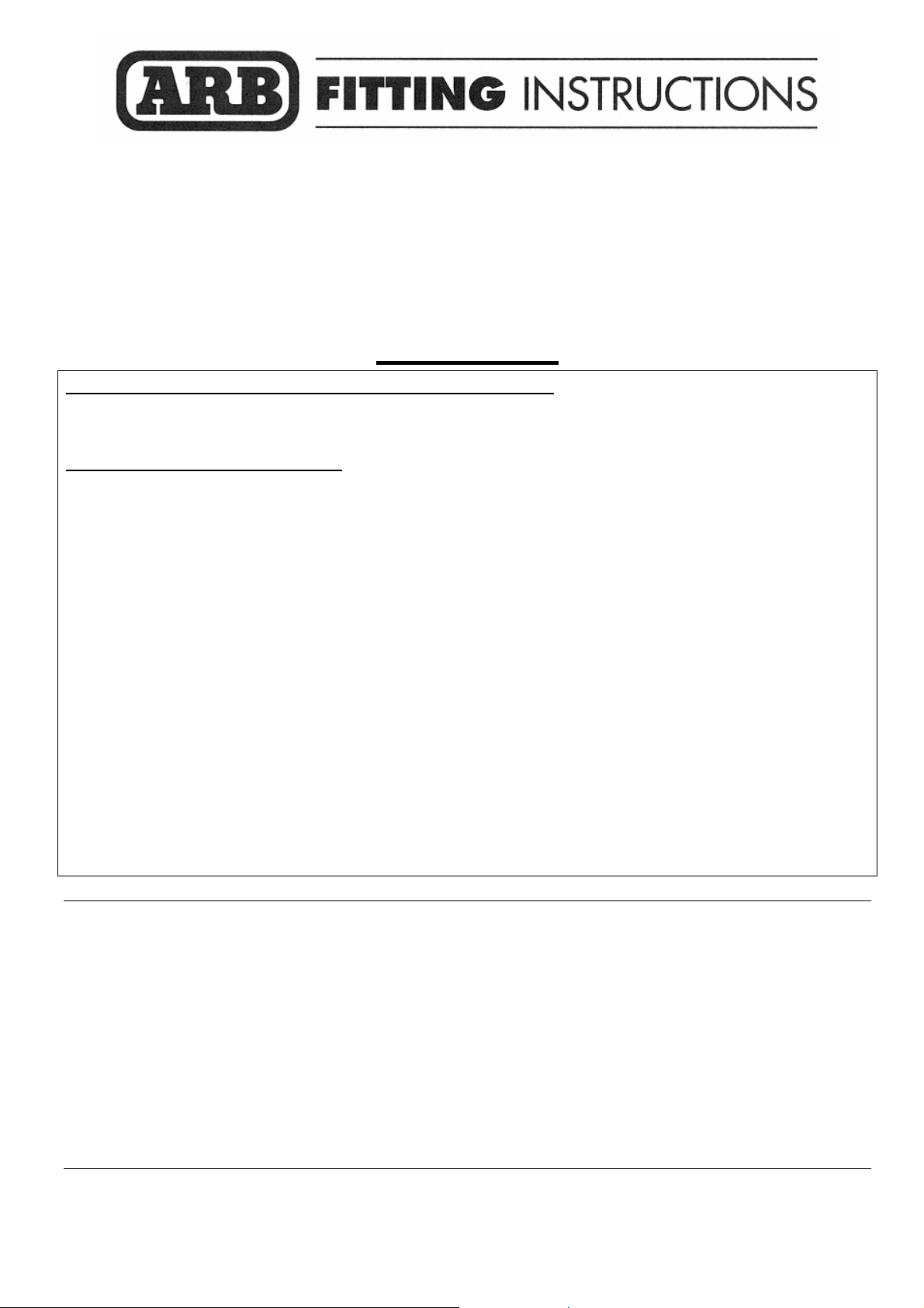
4. Remove the four lower bolts that attach the
lower bumper tabs to the vehicle (refer to
attached photo). There are also another two
self tapping screws in each side, located in a
recess in the lower bumper face – these need
to be removed.
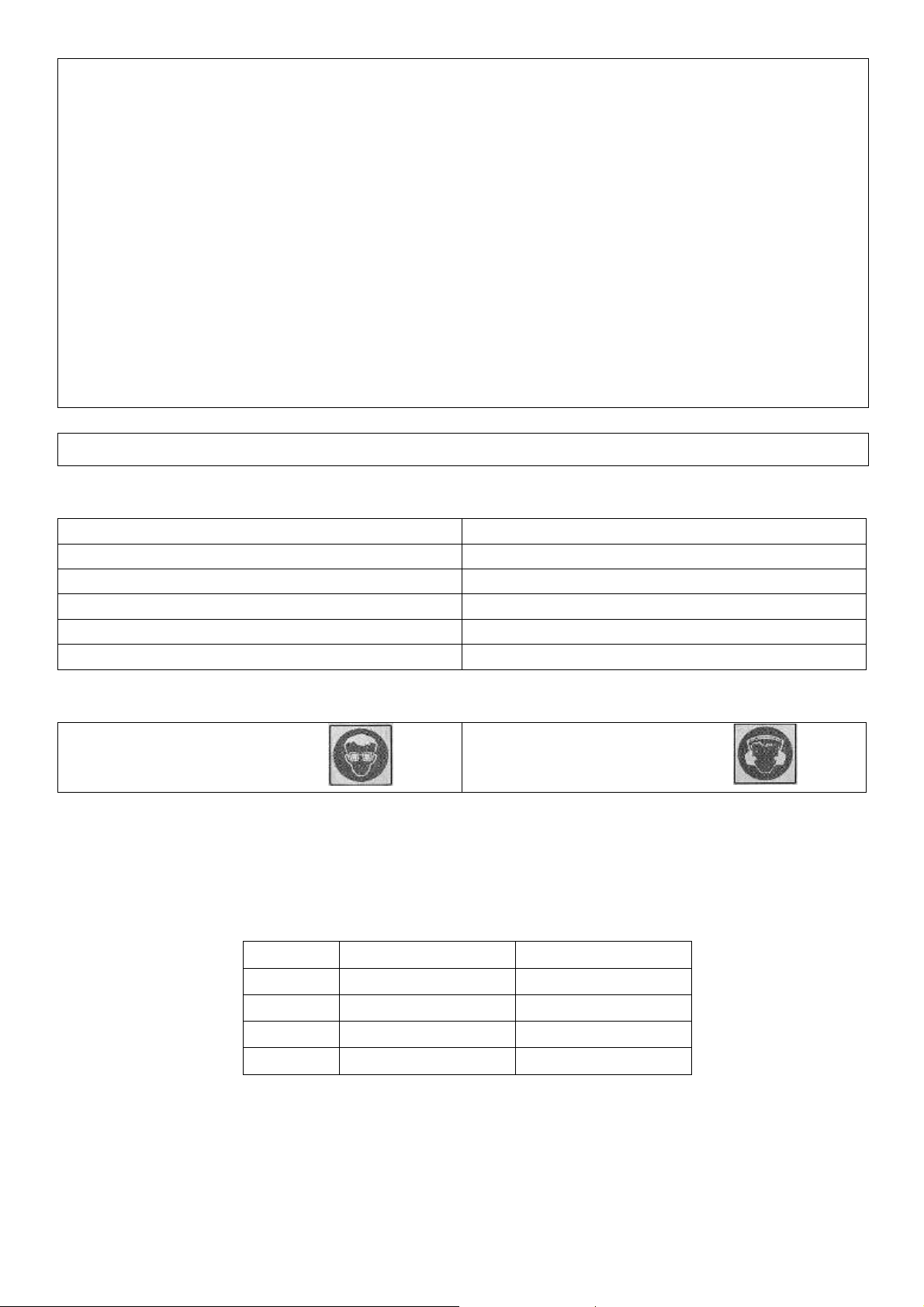
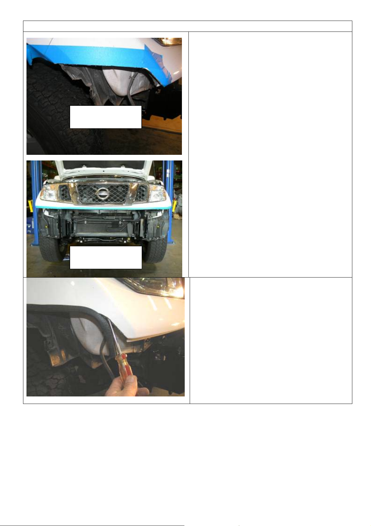
5. Remove the two bolts and screw from the
fender opening area each side that attaches
the bumper bar to the plastic inner guard liner
as shown.
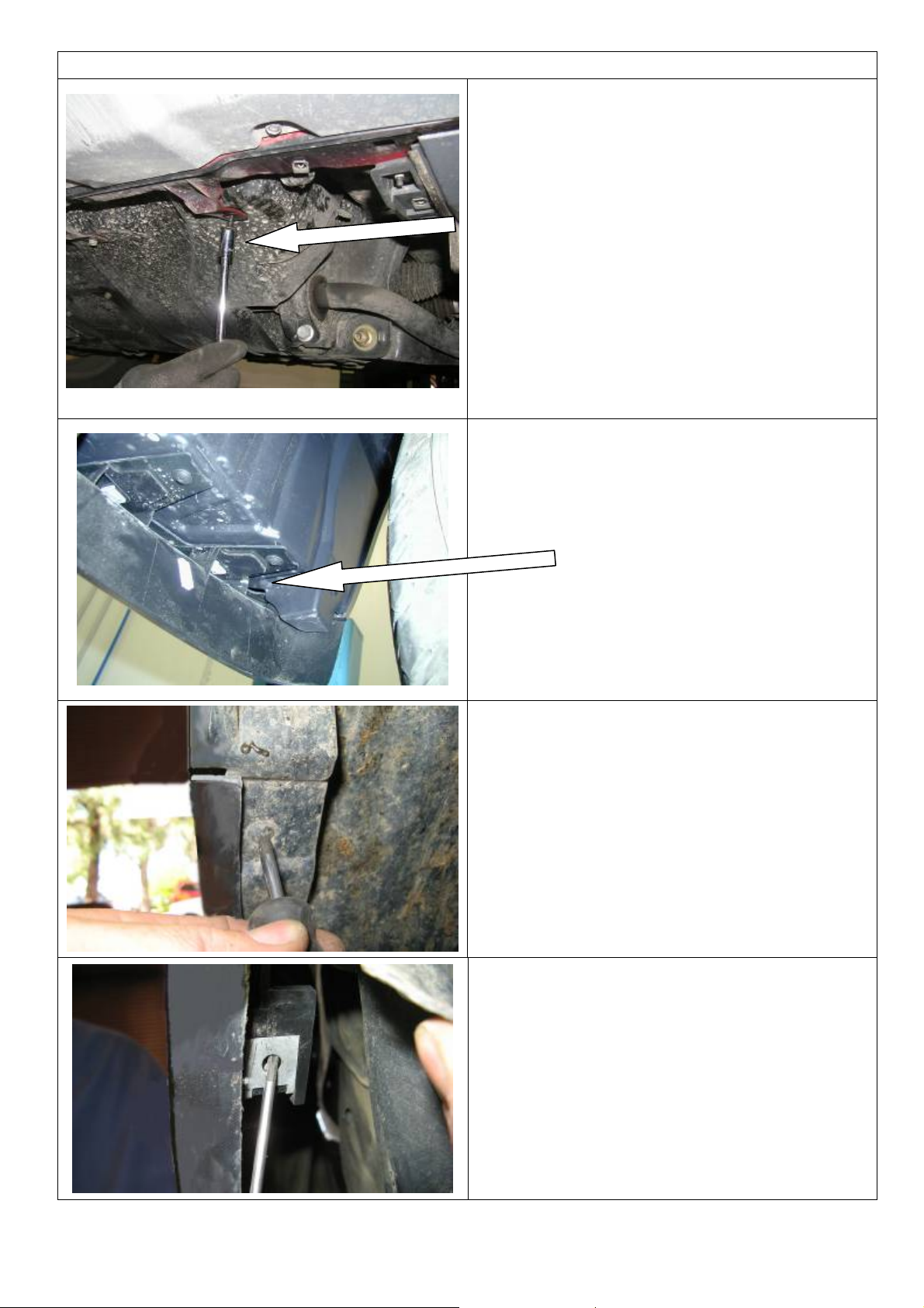
6. Remove the screws securing the fender liners
to bumper in the forward wheel arch areas
7. Remove the screws and speed nuts from the
bumper on each side in the wheel arch area
located vertically above wheel and tire.
Last Rev Date: 17/11/2009 Page 4 of 18 Fitting instructions# 3787059
Copyright © 2005 by ARB Corporation Limited. All rights reserved, this document must not be reproduced without the express authority of ARB Corporation Ltd
Page 5
PREPARATION TO VEHICLE
8. Remove the grille
9. Remove the bumper (disconnect fog lamps if
fitted)
10. With the bumper on a soft non abrasive
surface, undo the bolts securing the upper
and lower halves then split the bumper and
refit only the top section to the vehicle
Align with split
line and wheel
arch
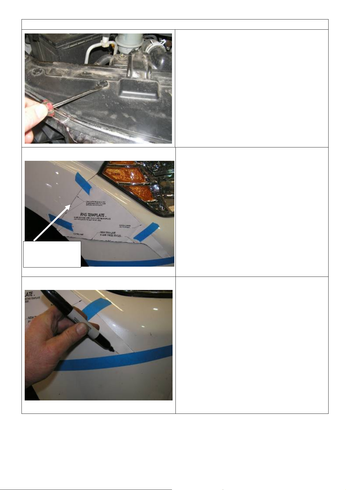
11. Cut out the supplied paper template
12. Fit the cutting template as shown, aligning the
key reference points with the bumper then
tape in position
13. Mark the cutting line with a marking pen
14. Remove and reverse then fit the template to
the LHS, mark the cutting line once again.
Last Rev Date: 17/11/2009 Page 5 of 18 Fitting instructions# 3787059
Copyright © 2005 by ARB Corporation Limited. All rights reserved, this document must not be reproduced without the express authority of ARB Corporation Ltd
Page 6
PREPARATION TO VEHICLE
View in wheel arch
area after cutting
15. Remove the template then mask the area to
be cut with 50 mm masking tape to protect
the surrounding surfaces.
16. Cut from wheel arch area first on each side
with the electric jig saw, a second cut may be
necessary to fully cut the support structure
that sits behind the bumper bar.
17. Clean up the cut edges of the bumper bar
with a file or fine sand paper.
View after cutting
18. Starting at the wheel opening end pull the
outer bumper outward slightly and slip the
trim over the cut edge and work the trim
forward.
HINT: You can use a flat blade screwdriver to
prise the bumper away from the reinforcing
structure behind so the trim can be inserted
Last Rev Date: 17/11/2009 Page 6 of 18 Fitting instructions# 3787059
Copyright © 2005 by ARB Corporation Limited. All rights reserved, this document must not be reproduced without the express authority of ARB Corporation Ltd
Page 7

PREPARATION TO VEHICLE
19. If fitted trim air deflectors both sides as
shown at horizontal line with a hacksaw
blade or sharp cutting blade and discard the
lower section as shown
20. Only if fitted and interfering with mount
bracket, remove the bracket holding the
power steering pipe
21. Mark out a hole 20mm (3/4”) up from the
original upper hole
22. Drill out to same diameter as upper hole as
shown
23. Then flatten tab.
24. Touch up bare surfaces with rust preventing
paint.
Last Rev Date: 17/11/2009 Page 7 of 18 Fitting instructions# 3787059
Copyright © 2005 by ARB Corporation Limited. All rights reserved, this document must not be reproduced without the express authority of ARB Corporation Ltd
Page 8

PREPARATION TO VEHICLE
25. Pull up pipe and refit bracket as shown
26. The bumper reinforcement beam is now
visible.
27. Remove the four bolts that hold the factory
steel sump guard, set aside to be fitted once
bull bar is fitted.
28. The four bolts that hold the bumper
reinforcement beam can now be removed
and set aside.
29. Remove tow hook and set aside. Hook will
be reused as well as bolt set
Last Rev Date: 17/11/2009 Page 8 of 18 Fitting instructions# 3787059
Copyright © 2005 by ARB Corporation Limited. All rights reserved, this document must not be reproduced without the express authority of ARB Corporation Ltd
Page 9

PREPARATION TO VEHICLE
30. Install the impact absorber set as shown
31. Secure hand tight only, using M12 x1.25 X
35 bolt, washer and flange nut sets.
32. Use the original bolts to secure the tow hook
if it is to be refitted
33. Check the overall width of the mount
brackets by measuring the distance inside
the faces as shown. The two inside vertical
faces should be parallel to each other.
34. For reference, the ideal width is 910mm. If
the width is over this or well under, adjust the
brackets to achieve approximately this width
leaving the bolts snugged up, not finish
torqued.
Last Rev Date: 17/11/2009 Page 9 of 18 Fitting instructions# 3787059
Copyright © 2005 by ARB Corporation Limited. All rights reserved, this document must not be reproduced without the express authority of ARB Corporation Ltd
Page 10

BULL BAR PREPARATION
35. Fit the buffers to either side of the bull bar
using 6 x M6 flange nuts. Do not over tighten.
36. Fit M6 cage nuts to four holes in lower pan
flange. The nut bodies are inside the bull bar
IF NOT FITTING A WINCH
37. Apply rubber mould to edge of winch hole
cover panel and trim off excess.
38. Fit panel to top face on bull bar using 2 x M6
dome head stainless steel screws, flange nuts
and flat washers.
NOTE: The flat washers are to be sandwiched
between panel and top face of bull bar to stop
the panel pulling down to form depression
around screw heads.
Last Rev Date: 17/11/2009 Page 10 of 18 Fitting instructions# 3787059
Copyright © 2005 by ARB Corporation Limited. All rights reserved, this document must not be reproduced without the express authority of ARB Corporation Ltd
Page 11

WINCH FITMENT ONLY
IF FITTING A WINCH
39. Rotate the winch motor 90 degrees as shown,
so that the terminals are facing upwards once
winch is fitted to bull bar
NOTE: Follow the winch manufacturers
instructions regards motor rotation and
drainage requirements
40. Remove the cap head screws retaining the
gearbox to the winch drum. Carefully lift the
gearbox a small amount (5 mm ) and
rotate144 degrees counter clockwise (four
hole spacings) and re-fit the cap screws . This
places the winch handle in the correct
orientation.
41. Lay the winch on a suitable flat surface and
place the bull bar on top so that the wire rope
will feed thru from the bottom.
42. Using the two 3/8” x 1 1/2”long bolts, M10 flat
and spring washers, attach the bull bar to the
winch through the top two bolt holes as
shown.
Fit two top 1 ½” long
bolts first
Last Rev Date: 17/11/2009 Page 11 of 18 Fitting instructions# 3787059
Copyright © 2005 by ARB Corporation Limited. All rights reserved, this document must not be reproduced without the express authority of ARB Corporation Ltd
Page 12

WINCH FITMENT ONLY
43. Using a 12mm drill bit, mark & drill two new
holes in the roller fairlead 25mm below the
original holes.
Drill the new
hole 25mm
below
Warning: Drilling operations can result in flying
metal debris, safety glasses should be worn.
44. Remove the cir clips from the bottom of the
vertical rollers of the fairlead and push the pin
upwards. Push the vertical rollers inwards on
the lower edges as shown and using two 3/8”
x 1 ¾” bolts M10 flat and spring washers,
attach the lower section of the roller fairlead
to the bull bar and winch.
45. Replace the cir clips on the vertical rollers
on both sides.
46. Insert the two rubber grommets into the top
face of bull bar.
Last Rev Date: 17/11/2009 Page 12 of 18 Fitting instructions# 3787059
Copyright © 2005 by ARB Corporation Limited. All rights reserved, this document must not be reproduced without the express authority of ARB Corporation Ltd
Page 13

WINCH FITMENT ONLY
47. Attach the control box to the control box
bracket as shown.
48. Fit the control box to the bull bar with two M8
x 25mm bolts, M8 flat washers and M8 flange
nuts.
49. Run the cables through the rubber grommets
and connect to the winch as per the wiring
diagram supplied with the winch.
50. Using cable ties fix the cables securely and
ensure they are well away from any moving,
sharp or hot surfaces.
BULL BAR FITMENT TO VEHICLE
51. With assistance guide the bull bar into
position on the vehicle. The uprights on the
bull bar sit inside the impact absorber blades.
52. Bolt the bull bar into position using the M12
bolts, spring washer, large body washer and
flange nuts 3 places each side as shown.
Tighten the bolts firmly – but allow enough
movement for the bull bar to be adjusted
Last Rev Date: 17/11/2009 Page 13 of 18 Fitting instructions# 3787059
Copyright © 2005 by ARB Corporation Limited. All rights reserved, this document must not be reproduced without the express authority of ARB Corporation Ltd
Page 14

BULL BAR FITMENT TO VEHICLE
53. Ensure the bull is sitting on the vehicle level
and the gap between the bumper bar and the
bull bar wing is parallel.
15 / 18 mm (5/8”) GAP
REQUIRED
54. If the bar is not centred on the vehicle, tap the
mount brackets sideways with a soft hammer
until the bar is central
55. Once happy with the position of the bull bar
and the clearance gap is between 15mm – 18
mm tighten all the mount bolts to specified
torque
56. The stone shield cross brace can now be
fitted to the flange attached to the impact
absorber using an M8 bolt, spring washer, flat
washer and M8 flange nut set per side.
57. Tighten both sides.
58. Install the two M6 cage nuts (long leg) with
the body of the nut facing upward.
Flanges face
forward
59. Using an electric drill and a 10.0 mm drill bit,
drill two pinning bolt holes through the bull
bar upright each side using the holes in the
mount bracket flanges as a guide. One hole
is located in the lower lug of the mount face
and one up above the welded nuts. Use
access through the light surround opening for
the top hole.
Warning: Drilling operations can result in flying
metal debris, safety glasses should be worn.
Last Rev Date: 17/11/2009 Page 14 of 18 Fitting instructions# 3787059
Copyright © 2005 by ARB Corporation Limited. All rights reserved, this document must not be reproduced without the express authority of ARB Corporation Ltd
Page 15

BULL BAR FITMENT TO VEHICLE
60. Fit the pinning bolts to the bull bar in the
drilled positions using 4 x M10 SEMS bolt and
washer sets and M10 flange nuts.
M10 PINNING BOLT
61. Assemble and install combination light
surrounds (p/n 3163015) as per instructions
no. 3786421 supplied with surround kit. Note:
Optional fog lamps can be installed at this
point as per fitting instruction no. 3783315
supplied with fog lamp kit no. 6821201.
62. Wire the combination lamp to the vehicles
indicator and clearance lamp wiring.
Caution: Cable tie all cables together and
keep all cables clear of sharp edges and
moving parts.
Wiring ARB supplied turn signal:
Green wire is Turn signal + (pos)
Red is running lamp + (pos)
Black is – (neg)
63. Attach the stone tray to the under side of
the bull bar with the black M6 bolts, flat
washers & spring washers.
There are four bolts in the front edge
and two in the back edge.
Last Rev Date: 17/11/2009 Page 15 of 18 Fitting instructions# 3787059
Copyright © 2005 by ARB Corporation Limited. All rights reserved, this document must not be reproduced without the express authority of ARB Corporation Ltd
Page 16

BULL BAR FITMENT TO VEHICLE
64. The licence plate can now be attached to
the bull bar. Insert the two plastic square
plugs supplied into the two square holes in
the face of the bull bar.
65. If winch fitted, position the licence plate as
shown fastening using lower holes. If winch
not fitted use the top row of holes, licence
plate is positioned lower and covers RFL
opening in front of bull bar
66. Using the two dome head screws supplied
screw into position firmly.
67. Trim the fender liner horizontally level with
the bottom edge of the bull bar wing
68. Trim the fender liner vertical edge so that it
has about 20mm (3/4”) overlap to clip in
behind wing return
Last Rev Date: 17/11/2009 Page 16 of 18 Fitting instructions# 3787059
Copyright © 2005 by ARB Corporation Limited. All rights reserved, this document must not be reproduced without the express authority of ARB Corporation Ltd
Page 17

ONCE BAR IS FITTED:
BULL BAR FITMENT TO VEHICLE
69. Push the outer edge of the liner forward
past the wing return edge so that it snaps in
against the wing brace as shown.
♦ Ensure all bolts are tensioned correctly
♦ All wiring is clear of sharp edges or moving surfaces and secured
properly
♦ Piping is secured well away from sharp or moving components
♦ Check operation of winch if fitted
♦ Check all wiring and turn signal lamps are functioning correctly
Last Rev Date: 17/11/2009 Page 17 of 18 Fitting instructions# 3787059
Copyright © 2005 by ARB Corporation Limited. All rights reserved, this document must not be reproduced without the express authority of ARB Corporation Ltd
Page 18

FITTED PRODUCT
Last Rev Date: 17/11/2009 Page 18 of 18 Fitting instructions# 3787059
Copyright © 2005 by ARB Corporation Limited. All rights reserved, this document must not be reproduced without the express authority of ARB Corporation Ltd
 Loading...