

Page 1
K
Service Source
Macintosh SE
Page 2
K
Service Source
Basics
Macintosh SE
Page 3
Basics Overview - 1
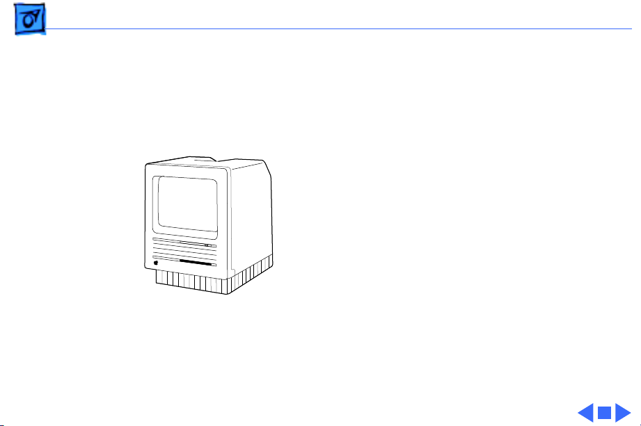
Overview
This manual contains
complete repair procedures
for the Macintosh SE, shown
at left.
Figure: Macintosh SE
Page 4
K
Service Source
Specifications
Macintosh SE
Page 5

Specifications Processor - 1
Processor
CPU
Motorola 68000 microprocessor
7.83 MHz
32-bit architecture
Page 6

Specifications Memory - 2
Memory
RAM
ROM
PRAM
1 or 2 MB, expandable to 4 MB
256K
256 bytes of memory
CMOS custom chip with seven-year lithium battery
Page 7

Specifications Disk Storage - 3
Disk Storage
Floppy Drive
Hard Drive
1.4 MB floppy drive
Optional second internal and external floppy drive
Optional 20 or 40 MB hard drive
Optional external hard drive
Page 8

Specifications I/O Interfaces - 4
I/O Interfaces
Expansion
SCSI
Apple Desktop Bus
Serial
Sound
Macintosh SE expansion slot; uses a 96-pin Euro-DIN connector
Uses a 50-pin connector (internal) and a DB-25 connector
(external)
Two Apple Desktop Bus (ADB) connectors for communication with
keyboard, mouse, and other input devices
Two RS-232/RS-422 serial ports; 230.4 Kbaud maximum; mini
DIN-8 connectors
For external audio amplifier (standard miniature)
Page 9

Specifications I/O Devices - 5
I/O Devices
Keyboards
Mouse
Apple Keyboard: 81 keys, including numeric keypad and cursor
keys
Apple Extended Keyboard: 105 keys, including 15 function keys,
separate cursor pad, and 10-key numeric keypad
Mechanical tracking; optical shaft at 3.94 pulses per mm (100
pulses per in.) of travel; ADB connector
Page 10

Specifications Sound and Video - 6
Sound and Video
Sound Generator
Video Display
Four-voice sound with 8-bit digital/analog conversion using 22-
kHz sampling rate
9-in. (diagonal) screen; high-resolution, 512 by 342 pixel,
bit-mapped display
Page 11

Specifications Electrical - 7
Electrical
Line V oltage
Frequency
Maximum Power
90–140 VAC; 170–270 VAC
47–63 Hz
100 W
Page 12

Specifications Physical - 8
Physical
Dimensions
Weight
Height: 13.6 in. (34.5 cm)
Width: 9.6 in. (24.4 cm)
Depth: 10.9 in. (27.6 cm)
17–21 lb. (7.7–9.5 kg)
Weight varies depending on whether hard drive or second floppy
drive is installed
Page 13

K
Service Source
Troubleshooting
Macintosh SE
Page 14

Troubleshooting General/ - 1
General
The Symptom Charts included in this chapter will help you
diagnose specific symptoms related to your product. Because cures
are listed on the charts in the order of most likely solution, try
the first cure first. Verify whether or not the product continues to
exhibit the symptom. If the symptom persists, try the next cure.
(Note: If you have replaced a module, reinstall the original module
before you proceed to the next cure.)
If you are not sure what the problem is, or if the Symptom Charts
do not resolve the problem, refer to the Flowchart for the product
family.
For additional assistance, contact Apple Technical Support.
Page 15

Troubleshooting Symptom Charts/Video - 2
Symptom Charts
Video
Screen is dark; audio
and drive operate
Screen is bright and
audio is present, but
no video information
is visible
1 Turn brightness control clockwise.
2 Check video cable connections.
3 Replace analog board.
4 Replace video board.
5 Replace logic board. Retain customer’s SIMMs.
6 Replace CRT.
1 Replace analog board.
2 Replace video board.
3 Replace logic board. Retain customer’s SIMMs.
Page 16

Troubleshooting Symptom Charts/Video
(Continued)
- 3
Screen is completely
dark and fan is not
running
Single vertical line is
displayed
Single horizontal line
is displayed
Video
1 Replace power supply.
2 Replace analog board.
1 Replace analog board.
2 Replace video board.
3 Replace logic board. Retain customer’s SIMMs.
4 Replace CRT.
1 Replace analog board.
2 Replace video board.
3 Replace logic board. Retain customer’s SIMMs.
4 Replace CRT.
(Continued)
Page 17

Troubleshooting Symptom Charts/Video
(Continued)
- 4
Vertical bars or
stripes are displayed
Horizontal bars or
stripes are displayed
White dot is displayed
in center of screen
Screen jitters at top
left and/or lower
right
Video
1 Replace logic board. Retain customer’s SIMMs.
2 Replace analog board.
1 Replace logic board. Retain customer’s SIMMs.
2 Replace analog board.
1 Verify that yoke cable is connected.
2 Replace analog board.
3 Replace CRT.
Replace analog board.
(Continued)
Page 18

Troubleshooting Symptom Charts/Peripheral - 5
Peripheral
Cursor does not move 1 Check mouse connection.
2 Inspect inside of mouse for buildup of dirt and other
contaminants. Clean mouse if necessary.
3 If mouse was connected to keyboard, connect it to ADB port
instead. If mouse works, replace keyboard.
4 If mouse does not work in any ADB port, replace mouse.
5 Replace logic board. Retain customer’s SIMMs.
Cursor moves, but
clicking mouse
button has no effect
No response to any
key on keyboard
1 Replace mouse.
2 Replace logic board. Retain customer’s SIMMs.
1 Check keyboard connection to ADB port.
2 Replace keyboard cable.
3 Replace keyboard.
4 Replace logic board. Retain customer’s SIMMs.
Page 19

Troubleshooting Symptom Charts/Peripheral
(Continued)
- 6
Cannot double-click
to open application,
disk, or server
Peripheral
1 Remove any multiple system files on hard drive.
2 Clear parameter RAM. (System 7: Hold down <Command>
<Option> <P> <R> during startup but before “Welcome to
Macintosh” appears. System 6: Hold down <Command>
<Option> <Shift> keys and select Control Panel from Apple
pull-down menu.) Reset mouse controls.
3 If mouse was connected to keyboard, connect it to ADB port
instead. If mouse works, replace keyboard.
4 If mouse does not work in any ADB port, replace mouse.
5 Replace logic board. Retain customer’s SIMMs.
(Continued)
Page 20

Troubleshooting Symptom Charts/Peripheral
(Continued)
- 7
Known-good
LaserWriter does not
print
Known-good
ImageWriter or
ImageWriter II does
not print
Peripheral
1 Make sure that Chooser and Control Panel are set correctly.
2 Make sure correct version of system software is being used.
Make sure software is known-good.
3 Reset PRAM.
4 Refer to Networks and Communications manual.
1 Make sure that Chooser and Control Panel are set correctly.
2 Make sure correct version of system software is being used.
Make sure software is known-good.
3 Reset PRAM.
4 Replace printer interface cable.
5 Replace logic board. Retain customer’s SIMMs.
(Continued)
Page 21

Troubleshooting Symptom Charts/Floppy Drive - 8
Floppy Drive
Audio and video are
present, but one
internal floppy drive
does not operate
External floppy drive
does not operate
Disk ejects; display
shows icon with
blinking “X”
1 Replace bad disk.
2 Replace floppy drive data cable.
3 Replace internal floppy drive.
4 Replace logic board. Retain customer’s SIMMs.
1 Replace bad disk.
2 Make sure external floppy drive is on right side of Macintosh
SE/30.
3 Replace external drive.
4 Replace logic board. Retain customer’s SIMMs.
1 Replace disk with known-good system disk.
2 Replace floppy drive.
3 Replace logic board. Retain customer’s SIMMs.
Page 22

Troubleshooting Symptom Charts/Floppy Drive
(Continued)
- 9
Floppy Drive
Unable to insert disk
all the way
Internal floppy drive
runs continuously
Does not eject disk 1 Insert opened paper clip into hole beside drive.
1 Insert opened paper clip into hole beside drive.
2 Switch off system power and hold mouse button down while
switching power back on (to complete eject cycle).
3 Replace floppy drive.
1 Replace bad disk.
2 Replace floppy drive.
3 Replace logic board. Retain customer’s SIMMs.
4 Replace floppy drive data cable.
2 Switch off system and hold mouse button down while
switching system back on (to complete eject cycle).
3 Replace floppy drive.
(Continued)
Page 23

Troubleshooting Symptom Charts/Floppy Drive
(Continued)
- 10
Audio and video are
present, but neither
internal floppy drive
operates
Floppy Drive
1 Replace bad disk.
2 Replace logic board. Retain customer’s SIMMs.
(Continued)
Page 24

Troubleshooting Symptom Charts/Hard Drive - 11
Hard Drive
Internal or external
hard drive does not
operate
Works with internal
or external SCSI
device but not with
both
1 Verify that SCSI loopback card is not attached.
2 Replace hard drive data cable.
3 Replace hard drive.
4 Replace logic board. Retain customer’s SIMMs.
1 Verify SCSI device switch setting on external device.
2 Replace terminator on external device.
3 Verify that terminator is installed on internal hard drive.
4 Replace hard drive select cable.
Page 25

Troubleshooting Symptom Charts/Miscellaneous - 12
Miscellaneous
Clicking, chirping,
or thumping sound
Smoke/odor 1 Replace power supply.
No video, no audio, and
no drive operation
1 Verify analog board cable is connected at J12 on logic board.
2 Replace power supply.
3 Replace analog board.
4 Replace logic board. Retain customer’s SIMMs.
2 Replace analog board.
1 Connect power cord.
2 Switch power on.
3 Replace power cord.
4 Replace power supply.
5 Replace analog board.
6 Replace logic board. Retain customer’s SIMMs.
Page 26

Troubleshooting Symptom Charts/Miscellaneous
(Continued)
- 13
Miscellaneous
“Sad Macintosh” icon 1 Replace bad disk.
2 Replace SIMM(s) if code matches any of those given in
“Isolating a Faulty SIMM” in Hardware/Memory.
3 Verify that three-pin jumper on logic board is configured
correctly for system RAM. See Hardware/Memory.
4 Replace logic board. Retain customer’s SIMMs.
“Sad Macintosh” icon
and black vertical
line are displayed;
screeching sound
1 Verify that three-pin jumper on logic board is configured
correctly for system RAM. See Hardware/Memory.
2 Replace logic board. Retain customer’s SIMMs.
(Continued)
Page 27

K
Service Source
T ak e Apart
Macintosh SE
Page 28
Take Apart Cover - 1
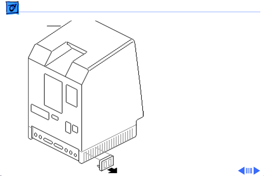
Cover
Cover
No preliminary steps are
required before you begin
this procedure.
±
Warning:
contains high voltage and a
high-vacuum picture tube.
To prevent serious injury,
review CRT safety in
Bulletins/Safety.
1 Using a small
screwdriver, pry off
the reset/interrupt
switch (if present).
This product
Page 29
Take Apart Cover - 2
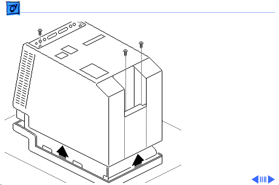
2 Using a Torx
screwdriver, remove
the four case screws and
separate the cover from
the chassis with a pullapart tool.
3 Carefully lift up the
cover and set it aside.
4 Remove the paper
insulating shroud from
the bottom of the
computer.
Page 30

Take Apart Cover - 3
Replacement Note:
Reinstall the two black case
screws in the bottom of the
cover and the two silvercolored case screws in the
top of the cover.
Page 31

Take Apart Analog Board & Power Supply - 4
Analog Board
Power
Supply
Analog Board & Power Supply
Before you begin,
• Remove the cover
• Discharge the CRT
• R emove the anode cap
Caution:
discharge the CRT to the
ground lug. Failure to do so
could damage the logic board
or the analog board.
Caution:
grounding wriststrap until
after discharging the CRT.
Be sure to
Never use a
Page 32

Take Apart Analog Board & Power Supply - 5
1 Carefully pull the video
board straight off the
neck of the CRT.
2 Remove the screw that
secures the power
supply ground wire to
the chassis.
Video Board
Ground Wire
Page 33

Take Apart Analog Board & Power Supply - 6
Yoke Cable
Logic Board Cable
3 Disconnect these cable
connectors from the
analog board:
• Yoke cable (First
depress the tab.)
• Logic board cable
• Video board cable
• Hard drive power
cable
Video
Board
Cable
Hard Drive
Power Cable
Page 34

Take Apart Analog Board & Power Supply - 7
4 Remove the four screws
that secure the analog
board to the chassis.
5 Remove the metal clip
from the corner of the
board.
Metal Clip
Page 35

Take Apart Analog Board & Power Supply - 8
6
Caution:
removing the analog
board, be careful not to
catch the brightness
control knob on the
chassis and not to bump
the neck of the CRT.
Grasp the analog board
by its edges and pull the
board up and out of the
chassis.
When
Page 36

Take Apart Analog Board & Power Supply - 9
7 Place the analog board on
a protective pad and
disconnect the power
supply cable.
Power Supply
Cable
Page 37

Take Apart Analog Board & Power Supply - 10
8 Remove the four screws
and separate the power
supply from the analog
board.
Brightness
Control Knob
Replacement Note:
If you
are replacing a defective
analog board, remove and
keep the brightness control
knob.
Page 38

Take Apart Analog Board & Power Supply - 11
Ferrite Bead
Replacement Note:
If you
receive a replacement analog
board that is packaged with a
ferrite bead, and if the
customer’s video cable does
not have a ferrite bead
attached, install the
packaged ferrite bead on the
video cable as shown.
Secure the ferrite bead to
the cable with a tie-wrap.
Replacement Note:
If you
replace the analog or power
supply, perform the video
adjustment procedure. See
“Video” in Adjustments.
Page 39

Take Apart Logic Board - 12
Logic Board
Before you begin,
• Remove the cover
• Discharge the CRT
Logic Board
Caution:
discharge the CRT to the
ground lug. Failure to do so
could damage the logic board
or the analog board.
Warning: Never use a
grounding wriststrap until
after discharging the CRT.
Be sure to
Page 40

Take Apart Logic Board - 13
Floppy Drive Cable
Power Supply Cable
Hard Drive
Data Cable
1 Carefully pull the video
board straight off the
neck of the CRT.
2 Disconnect these cable
connectors from the
logic board:
• Hard drive data cable
(if present)
• Internal floppy drive
cable(s)
• Power supply cable
Note:
You must first
depress the holding clip
to remove the power
supply cable.
Page 41

Take Apart Logic Board - 14
3 Slide up the logic board
until its tabs are aligned
with the notches in the
chassis. Swing out the
right side of the board
and remove it from the
chassis.
Page 42

Take Apart Logic Board - 15
4 Disconnect the speaker
cable from the logic
board.
Speaker Cable
Replacement Note:
If you
are replacing a defective
logic board, you must use an
exchange logic board that is
configured the same as the
customer’s original board.
See “Identifying SE Logic
Boards” in the Additional
Procedures chapter for
more information.
Page 43

Take Apart Video Board - 16
Video Board
Before you begin,
• Remove the cover
• Discharge the CRT
Video Board
Caution:
discharge the CRT to the
ground lug. Failure to do so
could damage the logic board
or the analog board.
Warning:
grounding wriststrap until
after discharging the CRT.
Be sure to
Never use a
Page 44

Take Apart Video Board - 17
1 Carefully pull the video
board straight off the
neck of the CRT.
2 Disconnect the video
board connector from the
analog board.
3 Remove the Torx screw
and video ground wire
from the upper-left
CRT mounting bracket.
Replacement Note:
replace the video board,
perform the video
adjustment procedure. See
“Video” in Adjustments.
If you
Page 45

Take Apart Video Board - 18
Replacement Note:
Replacement video boards
are installed vertically on
the CRT. The verticallymounted video board
requires using the axial
(round) fan.
Page 46

Take Apart CRT - 19
CRT
Before you begin,
• Remove the cover
• Discharge the CRT
• Remove the anode cap
• Remove the video board
CRT
• Remove the analog board
(only)
Page 47

Take Apart CRT - 20
1 With the CRT face-down
on a protective pad, use a
Torx screwdriver to
remove the three
remaining CRT
mounting screws.
2 Lift the CRT off the
bezel.
Replacement Note:
replace the CRT, perform
the video and yoke
adjustment procedures. See
“Video” and “Yoke” in the
Adjustments chapter.
If you
Page 48

Take Apart Hard Drive - 21
Hard Drive
Before you begin,
• Remove the cover
• Discharge the CRT
• Remove the video board
Hard Drive
Page 49

Take Apart Hard Drive - 22
Hard Drive
Power Cable
Hard Drive Data Cable
Warning:
Never use a
grounding wriststrap until
after discharging the CRT.
1 Disconnect the hard
drive data cable from the
hard drive and the logic
board. Keep the cable.
2 Disconnect the hard
drive power cable from
the analog board.
Page 50

Take Apart Hard Drive - 23
3 Remove the two
mounting screws and
lift out the hard drive
with carrier attached.
Replacement Note:
information on removing the
hard drive from the carrier
and returning drives,
cables, and carriers to
Apple, refer to “Additional
Procedures” in the Hard
Drives manual.
For
Page 51

Take Apart Hard Drive - 24
Revision A
Revision B
Replacement Note:
If you
are replacing a defective
Hard Disk 20SC, be aware
that Apple currently ships
Revision A and Revision B
versions of this hard drive
and each version must be
replaced like-for-like. To
differentiate between drive
versions, check their
circuit boards. For Revision
A drives, the component
side of the board is up; for
Revision B drives, the
solder side of the board is
up. For part numbers,
refer to the Service Source
parts database.
Page 52

Take Apart LED Cable Assembly - 25
LED Cable Assembly
Before you begin,
• Remove the cover
• Discharge the CRT
• Remove the hard drive
LED Cable Assembly
Page 53

Take Apart LED Cable Assembly - 26
1 Disconnect the LED
connector from the hard
drive.
2 Pull open the release
tab at the back of the LED
and push the LED
through the carrier
bracket.
Page 54

Take Apart Upper Floppy Drive - 27
Upper Floppy Drive
Before you begin,
• Remove the cover
• Discharge the CRT
• Remove the video board
Upper Floppy Drive
Page 55

Take Apart Upper Floppy Drive - 28
1 Disconnect the upper
floppy drive cable from
logic board connector J7.
2 Remove two mounting
screws and the metal
bracket that connects the
upper and lower floppy
drives.
Page 56

Take Apart Upper Floppy Drive - 29
3 Lift and slide out the
upper floppy drive.
Disconnect and keep the
floppy drive cable.
Floppy Drive
Cable
Replacement Note:
Apple
recommends using dust
shields on all 1.4 MB floppy
drives. All 1.4 MB
replacement drives ship
with the dust shield
installed. If you plan to
install a dust shield on an
existing 1.4 MB drive, you
must first clean the drive
(see the Hard Drives
manual).
Page 57

Take Apart Lower Floppy Drive - 30
Lower Floppy Drive
Before you begin,
• Remove the cover
• Discharge the CRT
• Remove the video board
• Remove the upper drive
• Remove the logic board
Lower Floppy Drive
Page 58

Take Apart Lower Floppy Drive - 31
Remove the four mounting
Floppy Drive
Cable
screws and lift out the lower
floppy drive. Disconnect and
keep the floppy drive cable.
Replacement Note:
Apple
recommends using dust
shields on all 1.4 MB floppy
drives. All 1.4 MB
replacement drives ship
with the dust shield
installed. If you plan to
install a dust shield on an
existing 1.4 MB drive, you
must first clean the drive
(see the Hard Drives
manual).
Page 59

Take Apart Fan Assembly - 32
Fan Assembly
Fan Assembly
Before you begin,
• Remove the cover
• Discharge the CRT
• Remove the video board
• Remove the analog board
and power supply.
Page 60

Take Apart Fan Assembly - 33
1 Compress the arrow
clips and remove the
insulating paper from
Arrow Clips
Insulating Paper
the analog board.
Page 61

Take Apart Fan Assembly - 34
2 Check the front and back
of the analog board for
wires connecting the fan
to the board. Desolder
Solder Point
these wires at their
solder points at the back
Solder Point
Solder Point
of the analog board.
Using a matte knife, cut
away any excess solder.
(Solder Side)
Fan Wires
Solder Point
Solder Point Solder Point
(Component Side)
Page 62

Take Apart Fan Assembly - 35
3 Remove the four
mounting screws and
lockwashers and remove
the fan assembly from
the analog board.
Note:
On earlier
versions of the analog
board you may have to
(Solder Side)
Fan Solder Points
desolder the fan itself
from the analog board at
the solder points shown.
Page 63

Take Apart Fan Assembly - 36
Replacement Caution:
you are replacing the fan
with the newer axial
(round) fan, make sure
your customer’s system has
the redesigned, verticallymounted video board
installed on the CRT. The
axial fan does not allow
adequate vibration
clearance with the old,
horizontally-mounted video
board.
If
Page 64

Take Apart Fan Assembly - 37
Black Wire
Yellow Wire
(Solder Side)
Replacement Note:
Some
replacement fans have a
black wire and a yellow wire
that must be soldered to the
back side of the analog board.
Insert these wires through
the arrow clip hole in the
board and solder them to the
points shown.
Page 65

Take Apart Speaker, Bezel, & Slot Cover - 38
Speaker, Bezel, & Slot Cover
Speaker, Bezel, &
Slot Cover
Before you begin,
• Remove the cover
• Discharge the CRT
• Remove the video board
• Remove the analog board
(only)
• Remove the logic board
Page 66

Take Apart Speaker, Bezel, & Slot Cover - 39
1 Remove the five Torx
screws and lift the
chassis (with attached
drives) off the front
bezel.
Page 67

Take Apart Speaker, Bezel, & Slot Cover - 40
2 To remove the speaker,
cut away (with a matte
knife) the melted
plastic that secures the
speaker to the inside of
the front bezel.
3 Lift out the speaker.
Page 68

Take Apart Speaker, Bezel, & Slot Cover - 41
4 To remove the slot
cover, cut away (with an
art knife) the melted
plastic that secures the
slot cover to the inside of
the front bezel.
5 To remove the front
bezel, remove the CRT.
(See “CRT” in Take
Apart).
Page 69

K
Service Source
Upgrades
Macintosh SE
Page 70

Upgrades Memory Upgrade - 1
Memory Upgrade
Before you begin,
• Remove the cover
• Discharge the CRT
• Remove the logic board
±
Logic Board
Warning:
contains high voltage and a
high-vacuum picture tube.
To prevent serious injury,
review CRT safety in
Bulletins/Safety.
±
Warning:
grounding wriststrap until
after discharging the CRT.
This product
Never use a
Page 71

Upgrades Memory Upgrade - 2
Note:
Two logic boards are
available for the Macintosh
SE. The original board uses a
solder-type resistor to
identify system memory
configurations; a resistor is
installed in R35 for 1 MB
and in R36 for 2 MB. The
revised logic board uses a
jumper to identify system
memory.
Resistor/Jumper
Slot 1
Slot 3
Slot 2
Slot 4
Page 72

Upgrades Memory Upgrade - 3
Note:
The Macintosh SE
requires 150-ns (or
faster) SIMMs. RAM speed is
indicated by the -xx number
after the manufacturer’s
part number (-15
indicates a 150-ns SIMM).
Page 73

Upgrades Memory Upgrade - 4
Logic Board with Resistor
Clip one end of resistor R35
or R36 and move the
resistor away from the
clipped lead.
Slot 1
Slot 3
Resistor
Slot 2
Slot 4
Replacement Note:
Clipping the resistor and
moving it away will allow
you to retack the resistor in
the future.
Page 74

Upgrades Memory Upgrade - 5
2.5 MB Upgrade
Install two 1 MB SIMMs in
slots 1 and 2 and install two
256K SIMMs in slots 3 and
4.
4 MB Upgrade
Install four 1 MB SIMMs in
slots 1 through 4.
Page 75

Upgrades Memory Upgrade - 6
Logic Board with Jumper
1 MB to 2.5 MB
Remove the two 256K
SIMMs from slots 3 and 4.
Install two 1 MB SIMMs in
slots 3 and 4. Remove the
jumper permanently.
1 MB to 4 MB
Remove all four 256K
SIMMs. Install four 1 MB
SIMMs. Remove the jumper
permanently.
Slot 1
Slot 3
Jumper
Slot 2
Slot 4
Page 76

Upgrades Memory Upgrade - 7
Note:
Disregard the jumper
label “2/4 M” on the logic
board. A 4 MB upgrade
requires the removal of the
jumper.Ê
Page 77

Upgrades Memory Upgrade - 8
2 MB to 2.5 MB
Install two 256K SIMMs in
slots 1 and 2. Remove the
jumper permanently.
2 MB to 4 MB
Install two 1 MB SIMMs in
slots 1 and 2. Remove the
jumper permanently.
Note:
Disregard the jumper
label “2/4 M” on the logic
board. A 4 MB upgrade
requires the removal of the
Slot 1
Slot 3
Slot 2
Slot 4
jumper.
Page 78

Upgrades Logic Board Upgrade - 9
Logic Board Upgrade
Before you begin,
• Remove the cover
• Discharge the CRT
• Remove the video board
• Remove the logic board
• Remove the analog board
(only)
• Remove the upper drive
• Remove the CRT
• Remove the bezel
Logic Board
Page 79

Upgrades Logic Board Upgrade - 10
±
Warning:
contains high voltage and a
high-vacuum picture tube.
To prevent serious injury,
review CRT safety in
Bulletins/Safety.
This product
Caution:
the CRT, wear a grounding
wriststrap to prevent ESD
damage to components.
After discharging
Page 80

Upgrades Logic Board Upgrade - 11
Note:
The Logic Board
Upgrade Kit for the
Macintosh SE includes the
SE/30 logic board, a new
bezel, a ferrite bead and tiewrap for EMI protection, a
new chassis and bracket, a
new RFI shroud, two labels,
and a return sheet that you
must fill out and return to
Apple with the SE logic
board.
Page 81

Upgrades Logic Board Upgrade - 12
Note:
The SE/30 logic
board requires a minimum
Chassis Bracket
of four identical RAM
SIMMs. Customers whose
Macintosh SE systems have
2.5 MB or less of RAM must
purchase additional RAM
SIMMs.
Note:
The new chassis
comes in two pieces (a
chassis and a bracket) that
you must assemble before
installation.
1 Install the bracket on the
chassis with three
mounting screws.Ê
Page 82

Upgrades Logic Board Upgrade - 13
2 Install the CRT on the
new bezel with three
Torx screws.
3 Remove the lower
floppy drive from the old
chassis and install it on
the new chassis. Refer
to “Lower Floppy
Drive” in Take Apart.
Page 83

Upgrades Logic Board Upgrade - 14
4 Install the new chassis
on the new bezel with
five Torx screws.
5 Install the hard drive or
upper floppy drive on
the new chassis. Refer
to “Hard Drive” or
“Upper Floppy Drive”
in Take Apart.
6 Replace the analog board.
Refer to “Analog Board”
in Take Apart.
7 Install the new SE/30
logic board. Refer to
“Logic Board” in Take
Apart.
Page 84

Upgrades Logic Board Upgrade - 15
8 Clasp the clip-on ferrite
bead around the video
board cable as near the
video board connector as
possible. Secure the
ferrite bead near the
connector with tiewraps.
9 Replace the video board.
Tie-Wrap
Refer to “Video Board”
in Take Apart.
10 Install the new
insulating shroud over
the bottom of the SE and
replace the cover. Refer
to “Cover” in Take
Apart.
Ferrite Bead
Page 85

Upgrades Logic Board Upgrade - 16
11 Attach the agency
approval label over the
previous agency label on
the back of the cover.
Drive Labels
Agency Approval Label
12 Attach the appropriate
drive label in the groove
to the left of the disk
drive slot on the new
bezel.
13 Install system software
(6.03 or later) and run
diagnostics on the
upgraded unit.
Page 86

Upgrades 1.4 MB Drive Upgrade - 17
1.4 MB Drive Upgrade
Before you begin,
• Remove the cover
• Discharge the CRT
• Remove the video board
• Remove the hard drive or
upper floppy drive
• Remove the logic board
• Remove the lower floppy
drive
Page 87

Upgrades 1.4 MB Drive Upgrade - 18
±
Warning:
contains high voltage and a
high-vacuum picture tube.
To prevent serious injury,
review CRT safety in
Bulletins/Safety.
±
Warning:
grounding wriststrap until
after discharging the CRT.
This product
Never use a
Page 88

Upgrades 1.4 MB Drive Upgrade - 19
Note:
The 1.4 MB
SuperDrive Upgrade Kit
available for the Macintosh
SE includes two new ROMs, a
SWIM disk controller chip,
an audio extension cable for
reducing EMI interference,
the new 1.4 MB SuperDrive,
system software, two labels,
and an Apple product return
form.
Page 89

Upgrades 1.4 MB Drive Upgrade - 20
Note:
The 1.4 MB
SuperDrive must be used
with system software
version 6.0.3 or higher or
the Macintosh SE mistakes
the high-density drive for
an 800K mechanism.
1 Using an IC extractor,
remove the IWM chip
and two ROM chips from
the logic board.
Page 90

Upgrades 1.4 MB Drive Upgrade - 21
2 Install the SWIM chip
and two new ROM chips
on the logic board as
follows:
• SWIM (344–0062)
at D8
• High ROM (342–
0701) at D6
RAM SIMMs
• Low ROM (342–
0702) at D7
Note:
The notch at one
end of the SWIM chip and
each ROM chip must face
RAM SIMMs
toward the RAM SIMMs.
Page 91

Upgrades 1.4 MB Drive Upgrade - 22
3 Install the lower floppy
drive (the new 1.4 MB
drive). Refer to “Lower
Floppy Drive” in Take
Apart.
4 Replace the logic board.
Refer to “Logic Board”
in Take Apart.
Page 92

Upgrades 1.4 MB Drive Upgrade - 23
5 Replace the hard drive
or upper floppy drive.
Refer to “Hard Drive”
or “Upper Floppy
Drive” in Take Apart.
6 Replace the video board
and the cover. Refer to
“Video Board” and
“Cover” in Take Apart.
7 Place the high density
drive label in the groove
next to the lower drive
slot. If appropriate,
place a second floppy
drive label next to the
upper drive slot.
Page 93

Upgrades 1.4 MB Drive Upgrade - 24
Note:
The high density
drive label may read
“FDHD,” “1.4 MB,” or
“SuperDrive.”
8 If necessary, install
system software (6.03
or higher) and run
diagnostics.
9 Fill out the Apple
product return form and
return it to Apple with
the two ROM chips and
the IWM chip.
Page 94

Upgrades 1.4 MB Drive Upgrade - 25
Note:
Give the customer the
audio extension cable and
explain its use. To reduce
EMI interference, the
customer must install the
audio extension cable with
the ferrite bead between the
audio cable and the audio
jack at the rear of the
computer.
Page 95

K
Service Source
Additional Procedures
Macintosh SE
Page 96

Additional Procedures Battery Verification - 1
Battery
Battery
Verification
Before you begin,
• Remove the cover
• Discharge the CRT
• Remove the logic board
±
Warning:
discarded improperly, the
lithium battery in the
Macintosh SE/30 could
explode. Review battery
handling and disposal
instructions in Bulletins/
Safety.
If handled or
Page 97

Additional Procedures Battery Verification - 2
±
Positive
Probe
Negative
Probe
Warning:
grounding wriststrap until
after discharging the CRT.
1 Set the voltmeter to the
10 volts DC scale.
2 Hold the positive probe
of the voltmeter to the
positive end of the
battery and the negative
probe to the negative
end of the battery.
3 If the battery voltage is
below 2.8 volts, replace
the battery. Refer to
“Battery Replacement”
in this chapter.
Never use a
Page 98

Additional Procedures Battery Replacement - 3
Battery
Battery
Replacement
Before you begin,
• Remove the cover
• Discharge the CRT
• Remove the logic board
±
Warning:
discarded improperly, the
lithium battery in the
Macintosh SE/30 could
explode. Review battery
handling and disposal
instructions in Bulletins/
Safety.
If handled or
Page 99

Additional Procedures Battery Replacement - 4
Caution:
grounding wriststrap until
after discharging the CRT.
Never use a
Page 100

Additional Procedures Battery Replacement - 5
Soldered Battery
1 Using wire clippers, cut
the battery leads at both
ends of the battery. Cut
the leads as close to the
logic board as you can
without touching the
board.
2 Return the battery to
Apple for proper
disposal. For battery
packaging and labeling
information, refer to the
instructions in
Bulletins/Safety.
 Loading...