

Page 1

Logic Express 9
Effects
Page 2

Copyright © 2009 Apple Inc. All rights reserved.
Your rights to the software are governed by the
accompanying software license agreement. The owner or
authorized user of a valid copy of Logic Express software
may reproduce this publication for the purpose of learning
to use such software. No part of this publication may be
reproduced or transmitted for commercial purposes, such
as selling copies of this publication or for providing paid
for support services.
The Apple logo is a trademark of Apple Inc., registered in
the U.S. and other countries. Use of the “keyboard” Apple
logo (Shift-Option-K) for commercial purposes without
the prior written consent of Apple may constitute
trademark infringement and unfair competition in violation
of federal and state laws.
Every effort hasbeen made to ensure thatthe information
in this manual is accurate. Apple is not responsible for
printing or clerical errors.
Note: Because Apple frequently releases new versions
and updates to its system software, applications, and
Internet sites,images shownin this manualmay be slightly
different from what you see on your screen.
Apple
1 Infinite Loop
Cupertino, CA 95014
408-996-1010
www.apple.com
Apple, the Apple logo, GarageBand, Logic, and Macintosh
are trademarks of Apple Inc., registered in the U.S. and
other countries.
Finder is a trademark of Apple Inc.
Other company and product names mentioned herein
are trademarks of their respective companies. Mention of
third-party products is for informational purposes only
and constitutes neither an endorsement nor a
recommendation. Apple assumes no responsibility with
regard to the performance or use of these products.
Page 3

Contents
An Introduction to the Logic Express Effects7Preface
About the Logic Express Effects7
About the Logic Express Documentation10
Additional Resources10
Amps and Pedals13Chapter 1
Amp Designer13
Bass Amp30
Guitar Amp Pro31
Pedalboard37
Delay Effects53Chapter 2
Echo54
Sample Delay54
Stereo Delay55
Tape Delay57
Distortion Effects59Chapter 3
Bitcrusher60
Clip Distortion61
Distortion Effect62
Distortion II63
Overdrive63
Phase Distortion64
Dynamics Processors67Chapter 4
Types of Dynamics Processors67
Compressor69
DeEsser72
Ducker74
Enveloper77
Expander79
Limiter80
Noise Gate81
3
Page 4

Preset Multipressor83
Silver Compressor84
Silver Gate85
Equalizers87Chapter 5
Channel EQ88
DJ EQ91
Fat EQ92
Single-Band EQs93
Silver EQ95
Filter Effects97Chapter 6
AutoFilter97
EVOC 20 Filterbank103
EVOC 20 TrackOscillator107
Fuzz-Wah119
Spectral Gate123
Imaging Processors127Chapter 7
Direction Mixer127
Stereo Spread130
Metering Tools133Chapter 8
BPM Counter133
Correlation Meter134
Level Meter Plug-in134
Tuner135
Modulation Effects137Chapter 9
Chorus Effect138
Ensemble Effect138
Flanger Effect140
Microphaser140
Modulation Delay141
Phaser Effect143
Ringshifter144
Rotor Cabinet Effect150
Scanner Vibrato Effect152
Spreader154
Tremolo Effect155
Pitch Effects157Chapter 10
Pitch Correction Effect157
Pitch Shifter II161
4 Contents
Page 5

Vocal Transformer162
Reverb Effects167Chapter 11
Plates, Digital Reverb Effects, and Convolution Reverb168
AVerb168
EnVerb169
GoldVerb172
PlatinumVerb175
SilverVerb179
Specialized Effects and Utilities181Chapter 12
Denoiser181
Enhance Timing183
Exciter184
Grooveshifter185
Speech Enhancer187
SubBass188
Utilities and Tools191Chapter 13
Gain Plug-in191
I/O Utility192
Test Oscillator194
5Contents
Page 6

Page 7

An Introduction to the Logic Express Effects
Logic Express has an extensive range of digital signal processing (DSP) effects and
processors that are used to color or tonally shape existing audio recordings, software
instruments, and external audio sources—in real time. These will cover almost every audio
processing and manipulation need you will encounter in your day-to-day work.
The most common processing options include EQs, dynamic processors, modulations,
distortions, reverbs, and delays.
Less common are simulations of amplifiers and speaker cabinets, which enable you to
“play” your instruments or other signals through a range of vintage and modern sound
reproduction systems. Guitarists will also benefit from a number of classic pedal effect
emulations.
Further advanced features include precise signal meters and analyzers, a test tone
generator, noise reduction, pitch correction, imaging, bass enhancement, andtime-altering
processors and utilities.
Preface
As you can see, many of the included processors and utilities don’t really fall into the
“effects” category, but they may prove to be invaluable in your studio.
All effects, processors, and utilities provide an intuitive interface that simplifies operation,
enabling you to work quickly. Outstanding audio quality is assured when needed, or—at
the other end of the spectrum—extreme processing is possible when you need to radically
alter your audio. All effects and processors are highly optimized for efficient CPU usage.
This preface covers the following:
• About the Logic Express Effects (p. 7)
• About the Logic Express Documentation (p. 10)
• Additional Resources (p. 10)
About the Logic Express Effects
Logic Express includes a comprehensive suite of effects processors and utilities that can
be used to enhance your music projects. Effects are grouped in the following categories.
7
Page 8

Included effectsEffect category
Amp DesignerAmp Modeling
Bass Amp
Guitar Amp Pro
Pedalboard
EchoDelay
Sample Delay
Stereo Delay
Tape Delay
BitcrusherDistortion
Clip Distortion
Distortion Effect
Distortion II
Overdrive
Phase Distortion
CompressorDynamics
DeEsser
Ducker
Enveloper
Expander
Limiter
Noise Gate
Preset Multipressor
Silver Compressor
Silver Gate
Channel EQEQ
DJ EQ
Fat EQ
Single-Band EQs
Silver EQ
AutoFilterFilter
EVOC 20 Filterbank
EVOC 20 TrackOscillator
Fuzz-Wah
Spectral Gate
8 Preface An Introduction to the Logic Express Effects
Page 9

Included effectsEffect category
Direction MixerImaging
Stereo Spread
BPM CounterMetering
Correlation Meter
Level Meter Plug-in
Tuner
Chorus EffectModulation
Ensemble Effect
Flanger Effect
Microphaser
Modulation Delay
Phaser Effect
Ringshifter
Rotor Cabinet Effect
Scanner Vibrato Effect
Spreader
Tremolo Effect
Pitch Correction EffectPitch
Pitch Shifter II
Vocal Transformer
AVerbReverb
EnVerb
GoldVerb
PlatinumVerb
SilverVerb
DenoiserSpecialized
Enhance Timing
Exciter
Grooveshifter
Speech Enhancer
SubBass
Gain Plug-inUtility
I/O Utility
Test Oscillator
9Preface An Introduction to the Logic Express Effects
Page 10

About the Logic Express Documentation
Logic Express comes with various documents that will help you get started as well as
provide detailed information about the included applications.
• Logic Express User Manual: This onscreen manual provides comprehensive instructions
for using Logic Express to set up a recording system, compose music, edit audio and
MIDI files, and output audio for CD productions.
• Exploring Logic Express: This booklet provides a fast-paced introduction to the main
features and tasks in Logic Express, encouraging hands-on exploration for new users.
• Logic Express Control Surfaces Support: This onscreen manual describes the configuration
and use of control surfaces with Logic Express.
• Logic Express Instruments: This onscreen manual provides comprehensive instructions
for using the powerful collection of instruments included with Logic Express.
• Logic Express Effects: This onscreen manual provides comprehensive instructions for
using the powerful collection of effects included with Logic Express.
• Logic Express Working with Apogee Hardware: This onscreen manual describes the use
of Apogee hardware with Logic Express.
Additional Resources
In addition to the documentation that comes with Logic Express, there are a variety of
other resources you can use to find out more.
Release Notes and New Features Documents
Each application offers detailed documentation that covers new or changed features and
functions. This documentation can be accessed in the following way:
• Open the application Help menu and choose Release Notes or New Features.
Logic Express Website
For general information and updates, as well as the latest news on Logic Express, go to:
• http://www.apple.com/logicexpress
Apple Service and Support Websites
For software updates and answers to the most frequently asked questions for all Apple
products, go to the general Apple Support webpage. You’ll also have access to product
specifications, reference documentation, and technical articles about Apple products and
products from other companies.
• http://www.apple.com/support
For software updates, documentation, discussion forums, and answers to the most
frequently asked questions for Logic Express, go to:
• http://www.apple.com/support/logicexpress
10 Preface An Introduction to the Logic Express Effects
Page 11

For discussion forums for all Apple products from around the world, where you can search
for an answer, post your question, or answer other users’ questions, go to:
• http://discussions.apple.com
11Preface An Introduction to the Logic Express Effects
Page 12

Page 13

Amps and Pedals
1
Logic Express features an extensive collection of guitar and bass amplifiers and classic
pedal effects. You can play live—or process recorded audio and software instrument
parts—through these amps and effects.
The amplifier models re-create vintage and modern tube and solid-state amps. Built-in
effect units, such as reverb, tremolo, or vibrato, are also reproduced. Accompanying the
amplifiers are a variety of emulated speaker cabinets, which can be used as a matching
set or combined in different ways to create interesting hybrids.
Also emulated are a number of “classic” foot pedal effects—or stompboxes—that were,
and remain, popular with guitarists and keyboardists. As with their real-world counterparts,
you can freely chain pedals in any order to create the perfect sound.
This chapter covers the following:
• Amp Designer (p. 13)
• Bass Amp (p. 30)
• Guitar Amp Pro (p. 31)
• Pedalboard (p. 37)
Amp Designer
Amp Designer emulates the sound of over 20 famous guitar amplifiers and the speaker
cabinets used with them. Each preconfigured model combines an amp, cabinet, and EQ
that re-creates a well-known guitar amplifier sound. You can process guitar signals directly,
which allows you to reproduce the sound of your guitar played through these amplification
systems. Amp Designer can also be used for experimental sound design and processing.
You are free to use it with other instruments, applying the sonic character of a guitar amp
to a trumpet or vocal part, for example.
The amplifiers, cabinets, and EQs emulated by Amp Designer can be combined in a
number of ways to radically or subtly alter the tone. Virtual microphones are used to pick
up the signal of the emulated amplifier and cabinet. You can choose from three different
microphone types, and you can reposition them.
13
Page 14
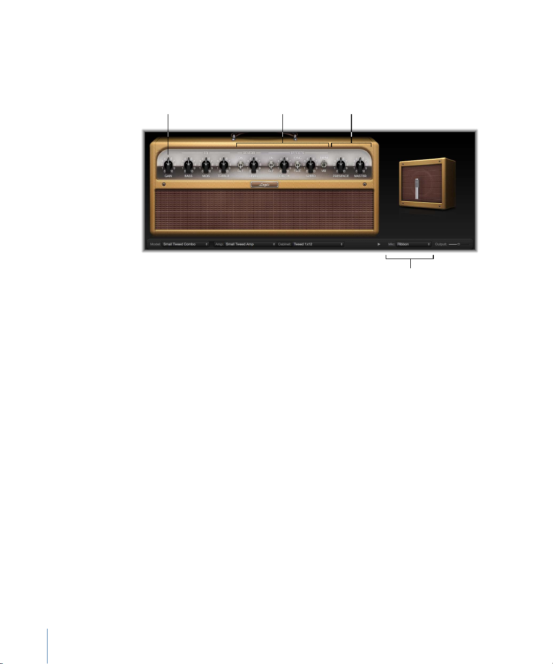
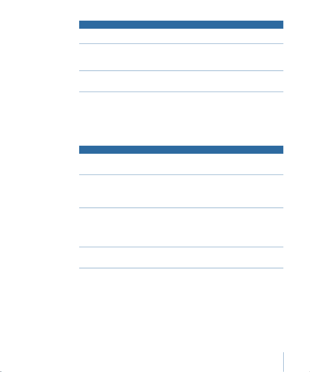
Amp parameters
Amp parameters
Effects parameters
Microphone parameters
Amp Designer also emulates classic guitar amplifier effects, including spring reverb,
vibrato, and tremolo.
The Amp Designer interface can be broken down into four general sections in terms of
different kinds of parameters.
• Model parameters: The Model pop-up menu is found at the left of the black bar at the
bottom. It is used to choose a preconfigured model, consisting of an amplifier, a cabinet,
an EQ type, and a microphone type. See Choosing an Amp Designer Model. The
model-customizing parameters on the black bar allow you to independently choose
the type of amplifier and cabinet. See Building a Customized Amp Designer Combo.
The EQ type is chosen from the EQ pop-up menu above the Bass, Mids, and Treble
knobs in the knobs section. See Using Amp Designer’s Equalizer.
• Amp parameters: Located at each end of the knobs section, these parameters are used
to set an amp’s input gain, presence, and output level. See Using Amp Designer’s Gain,
Presence, and Master Controls.
• Effects parameters: Located in the center of the knobs section, these parameters allow
you to control the integrated guitar effects. See Getting to Know Amp Designer’s Effects
Parameters.
• Microphone parameters: Located slightly above the right end of the black bar at the
bottom, these parameters are used to set the type and position of the microphone
that captures the amplifier and cabinet sound. See Setting Amp Designer Microphone
Parameters.
14 Chapter 1 Amps and Pedals
Page 15
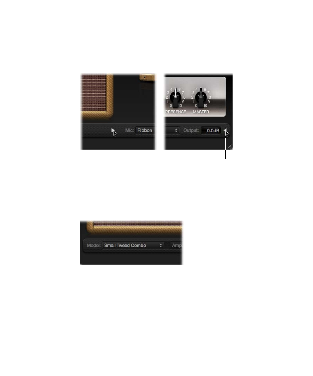
To switch between full and smaller versions of the interface
Click here in
full interface.
Click here in
small interface.
Click the disclosure triangle between the Cabinet and Mic pop-up menus in the full
µ
interface to switch to the smaller version. To switch back to the full interface, click the
disclosure triangle beside the Output field in the small interface. You can access all the
parameters, with the exception of microphone selection and positioning, in the small
interface.
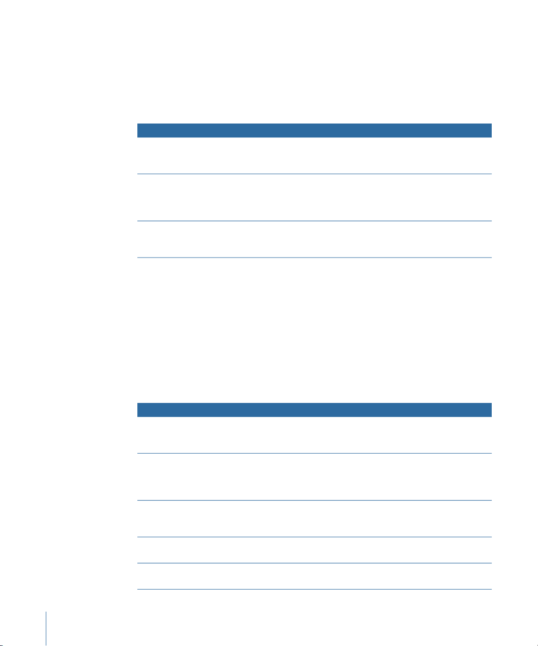
Choosing an Amp Designer Model
You can choose a preconfigured model—consisting of an amplifier, a cabinet, an EQ type,
and a microphone type—from the Model pop-up menu at the left end of the black bar
at the bottom of the Amp Designer interface. Your choices include several combinations
in each of the following categories:
• Tweed Combos
• Classic American Combos
• British Stacks
• British Combos
• British Alternatives
• Metal Stacks
• Additional Combos
15Chapter 1 Amps and Pedals
Page 16
Tweed Combos
The Tweed models are based on American combos from the 1950s and early 1960s that
helped define the sounds of blues, rock, and country music. They have warm, complex,
clean sounds that progress smoothly through gentle distortion to raucous overdrive as
you increase the gain. Even after half a century, Tweeds can still sound contemporary.
Many modern boutique amplifiers are based on Tweed-style circuitry.
DescriptionModel
Small Tweed Combo
Large Tweed Combo
Mini Tweed Combo
Tip: Tweed combos respond beautifully to your playing dynamics. Adjust the knobs to
create a distorted sound, then reduce the level of your guitar’s volume knob to create a
cleaner tone. Turn up your guitar’s volume knob when the time comes for a scorching
solo.
A 1 x 12" combo that transitions smoothly from clean to crunchy,
making it a great choice for blues and rock. For extra definition, set
the Treble and Presence controls to a value around 7.
This 4 x 10" combo was originally intended for bassists, but was also
used by blues and rock guitarists. More open and
transparent-sounding than the Small Tweed Combo, but can deliver
crunchy sounds.
A small amp with a single 10" speaker, used by countless blues and
rock artists. It is quite punchy-sounding, and can deliver the clean
and crunch tones that the Tweed combos are known for.
Classic American Combos
The Blackface, Brownface, and Silverface models are inspired by American combos of the
mid 1960s. These tend to be loud and clean with tight lows and relatively restrained
distortion. They are great for clean-toned rock, vintage R & B, surf music, twangy country,
jazz, or any other style where strong note definition is essential.
Large Blackface Combo
Silverface Combo
Mini Blackface Combo
Small Brownface Combo
Blues Blaster Combo
16 Chapter 1 Amps and Pedals
DescriptionModel
A 4 x 10" combo with a sweet, well-balanced tone favored by rock,
surf, and R & B players. Great for lush, reverb-drenched chords or
strident solos.
A 2 x 12" combo with a loud, ultra-clean tone. Its percussive,
articulate attack is great for funk, R & B, and intricate chord work. It
can be crunchy when overdriven, but most players favor it for clean
tones.
A 1 x 10" combo that is bright and open-sounding, with a surprising
amount of low-end impact. It excels at clean tones with just a hint
of overdrive.
A 1 x 12" combo that is smooth and rich-sounding, but retains a
nice level of detail.
A 1 x 15" combo that has a clear top end with a tight, defined low
end. This model is favored by blues and rock players.
Page 17

Tip: While these amps tend toward a clean and tight sound, you can use a Pedalboard
distortion stompbox to attain hard-edgedcrunch sounds witha biting treble and extended
low-end definition. See Distortion Pedals and Pedalboard.
British Stacks
The British Stack models are based on the 50- and 100-watt amplifier heads that have
largely defined the sound of heavy rock, especially when paired with their signature
4 x 12" cabinets. At medium gain settings, these amps are great for chunky chords and
riffs. Raising the gain yields lyrical solo tones and powerful rhythm guitar parts. Complex
peaks and dips across the tonal spectrum keep the tones clear and appealing, even when
heavy distortion is used.
DescriptionModel
Vintage British Stack
Modern British Stack
Brown Stack
British Blues Combo
Captures the sound of a late 1960s 50-watt amp famed for its
powerful, smooth distortion. Notes retain clarity, even at maximum
gain. After four decades this remains a definitive rock tone.
1980s and 1990s descendants of the Vintage British amplifier head,
which were optimized for hard rock and metal styles of the time.
The tones are deeper on the bottom, brighter on top, and more
“scooped” in the middle than the Vintage British amp.
Unique tones can be coaxed from a British head by running it at
lower voltages than its designers intended. The resulting “brown”
sound—often more distorted and loose than the standard
tone—can add interesting thickness to a guitar sound.
This 2 x 12" combo has a loud, aggressive tone that is cleaner than
the British heads, yet delivers fat distortion tones at high-gain
settings.
Tip: You’ll rarely go wrong combining a British head, a 4 x 12" cabinet, and a great riff at
high levels. But don’t hesitate to break that mold. These heads can sound stunning
through small cabinets, or at clean, low-gain settings. If the British Blues Combo is too
clean for your needs, combine it with Pedalboard’s Hi Drive stompbox for an aggressive
blues tone, or the Candy Fuzz stompbox for an explosive rock tone. See Distortion Pedals
and Pedalboard.
British Combos
The British Combos capture the brash, treble-rich sound that will forever be associated
with 1960s British rock and pop. The sonic signature of these amps is characterized by
their high-end response, yet they are rarely harsh-sounding due to a sweet distortion
and smooth natural compression.
DescriptionModel
British Combo
A 2 x 12" combo based on the early 1960s amps that powered the
British Invasion. Perfect for chiming chords and stabbing solos.
17Chapter 1 Amps and Pedals
Page 18
DescriptionModel
Small British Combo
Boutique British Combo
A 1 x 12" combo with half the power of the British Combo, this amp
offers a slightly darker, less open tone.
A 2 x 12" combo that is a modern take on the original 1960s sound.
The tone is thicker, with stronger lows and milder highs than the
other British Combos.
Tip: Using high Treble and Presence knob settings that might become strident on other
amp types can sound great with the British Combos.
British Alternatives
The late 1960s amplifier heads and combos that inspired the Sunshine models are loud
and aggressive, with full-bodied mid frequencies. These amps are not just for single note
solos and power chords, as they can sound great with big, open chords—one reason
why they were embraced by the “Brit-pop” bands of the 1990s. The Stadium amps are
famed for their ability to play ultra-loud without dissolving into mushy distortion. They
retain crisp treble and superb note definition, even at maximum gain settings.
DescriptionModel
Sunshine Stack
Small Sunshine Combo
Stadium Stack
Stadium Combo
A robust-sounding head paired with a 4 x 12" cabinet. It’s a great
choice for powerful pop-rock chords.
A 1 x 12" combo based on a modern amp known for a “big amp”
sound. It is brighter than the Sunshine Stack head, with a touch of
1960s British Combo flavor.
A classic head and 4 x 12" cabinet configuration popular with 1970s
arena rock bands. Its tones are cleaner than other Amp Designer
4 x 12" stacks, while still retaining body and impact. A good choice
if you need power and clarity.
A 2 x 12" combo based on a modern amp. The tone is a little
smoother and rounder than that of the Stadium Stack.
Tip: The tone of the Sunshine Stack can seem dark at times, but a high Treble knob setting
opens up the sound. While the Small Sunshine Combo sounds great with its default
1 x 12" cabinet, it also shines through a 4 x 12" cabinet. The Stadium amps can be slow
to distort, so most famous users have paired them with aggressive fuzz pedals. Try
combining it with Pedalboard’s Candy Fuzz or Fuzz Machine stompboxes. See Distortion
Pedals and Pedalboard.
Metal Stacks
The Metal Stack models are inspired by the powerful, ultra-high gain amplifier heads that
put the “chunk” into modern hard rock and metal music. All are paired with 4 x 12"
cabinets. Their signature tones range from heavy distortion to extremely heavy distortion.
If you want powerful lows, razor-edged highs, and serious sustain, these are the models
you should look to first.
18 Chapter 1 Amps and Pedals
Page 19
DescriptionModel
Modern American Stack
High Octane Stack
Turbo Stack
A powerful, ultra-high gain amp that is ideal for heavy rock and
metal. Use the Mids knob to set an ideal amount of scoop or boost.
Although a powerful, high-gain amp, this model offers a smooth
transition between gain settings andexcellent natural compression.
It is a great choice for fast soloing and for two- and three-note
chords.
An aggressive-soundingamp with spiky highs and noisy harmonics,
especially at high gain settings. Try the Turbo Stack when you need
to slice through a mix.
Tip: Combining the Turbo Stack with distortion and fuzz pedals may actually diminish
the amp’s edge. A dry sound is often the best choice for high-impact riffs.
Additional Combos
The combos and utility models in this category are versatile amps that can be used for a
wide variety of musical styles.
DescriptionModel
Studio Combo
Boutique Retro Combo
Pawnshop Combo
Transparent Preamp
A 1 x 12" combo based on boutique combos of the 1980s and 1990s
that use multiple gain stages to generate smooth, sustain-heavy
distortion without sacrificing bold, bright, clean sounds.
A 2 x 12" combo inspired by high-end modern amps that combine
the sounds of several great 1960s combos. It excels at shimmering
clean tones and crunch tones, making it a good choice when you
want an old-fashioned flavor, but with the crisp highs and defined
lows of a modern amplifier.
A 1 x 8" combo based on the inexpensive amps sold in American
department stores in the 1960s. Despite their limited features and
budget workmanship, these amps are the secret behind the sound
of many rock, blues, and punk players. The clean sounds are warm,
and distorted sounds are thick and satisfying, despite the small
speaker.
As the name suggests, a preamp stage with no coloration. You
should note that the Transparent Preamp is activated in the Amp
pop-up menu, not in the Model pop-up menu.
Tip: Try pairing the Studio Combo amp with one of the 4 x 12" cabinets for a heavier
sound. The Boutique Retro Amp has very sensitive tone controls, providing countless
tonal shadings. Even extreme settings can yield great results. Combine the Pawnshop
Combo amp with Pedalboard’s Hi Drive or Candy Fuzz stompboxes to emulate hard rock
tones of the late 1960s. See Distortion Pedals and Pedalboard.
19Chapter 1 Amps and Pedals
Page 20
Building a Customized Amp Designer Combo
Model pop-up menu
Cabinet pop-up menu
Amp pop-up menu
Mic pop-up menu
EQ pop-up menu
You can use one of the default models or you can create your own hybrid of different
amplifiers, cabinets, and so on, using the Amp, Cabinet, and Mic pop-up menus, located
on the black bar at the bottom of the interface. The EQ pop-up menu is accessed by
clicking the word EQ or Custom EQ toward the left of the knobs section.
Note: If you create your own hybrid amp combo, you can use the Settings menu to save
it as a setting file, which also includes any parameter changes you may have made.
Building an Amp Designer model is described in the following sections:
• Choosing an Amp Designer Amplifier
• Choosing an Amp Designer Cabinet
• Using Amp Designer’s Equalizer
• Setting Amp Designer Microphone Parameters
Choosing an Amp Designer Amplifier
You can choose an amplifier model from the Amp pop-up menu on the black bar at the
bottom of the Amp Designer interface. See the following sections for details on the
20 Chapter 1 Amps and Pedals
characteristics of each amplifier in these categories:
• Tweed Combos
• Classic American Combos
• British Stacks
• British Combos
• British Alternatives
• Metal Stacks
Page 21

• Additional Combos
Choosing an Amp Designer Cabinet
Cabinets have a huge impact on the character of a guitar sound (see Amp Designer
Cabinet Reference Table). While certain amplifier and cabinet pairings have been popular
for decades, departing from them is an effective way to create fresh-sounding tones. For
example, most players automatically associate British heads with 4 x 12" cabinets.
Amp Designer allows you to drive a small speaker with a powerful head, or to pair a tiny
amp with a 4 x 12" cabinet.
There’s nothing wrong with trying random combinations. But if you consider the variables
that determine a cabinet’s sound, you’ll be able to make educated guesses about
non-traditional amplifier and cabinet combinations. Some factors to consider:
Combos or Stacks
Combo amps include both an amplifier and speakers in a single enclosure. These usually
have an open back, so the sound resonates in multiple directions. The resulting sound is
“open”—with bright, airy highs and a general feeling of spaciousness. Amplifier “stacks”
consist of an amplifier head, with the speakers in a separate cabinet. These cabinets
generally have a closed back, and project the sound forward in a tight, focused “beam.”
They tend to sound more powerful than open-back cabinets, and typically have a tighter
low-end response at the expense of some high-end transparency.
Old or New Speakers
Amp Designer models that are based on vintage cabinets capture the character of aged
speakers. These may be a bit looser and duller-sounding than new speakers, but many
players prefer them for their smoothness and musicality. Sounds based on new cabinets
tend to have more snap and bite.
Large Speakers or Small Speakers
A larger speaker doesn’t guarantee a larger sound. In fact, the most popular bass guitar
cabinet of all time uses only small 8" speakers. Don’t be surprised if you get a deeper,
richer tone from a 10" speaker than from a large 4 x 12" cabinet. Try several sizes and
choose the one that works best for your music.
Single Speakers or Multiple Speakers
Guitarists sometimes use cabinets with multiple speakers, and not only for the larger
sound they tend to provide. Phase cancellations occur between the speakers, adding
texture and interest to the tone. Much of the “classic rock” sound, for example, has to do
with the tonal peaks and dips caused by this interaction between the speakers in a 4 x 12"
cabinet.
21Chapter 1 Amps and Pedals
Page 22

Amp Designer Cabinet Reference Table
You can choose a cabinet model from the Cabinet pop-up menu on the black bar at the
bottom of Amp Designer’s interface. The table below covers the properties of each cabinet
model available in Amp Designer.
DescriptionCabinet
Tweed 1 x 12
Tweed 4 x 10
Tweed 1 x 10
Blackface 4 x 10
Silverface 2 x 12
Blackface 1 x 10
Brownface 1 x 12
Brownface 1 x 15
Vintage British 4 x 12
Modern British 4 x 12
Brown 4 x 12
British Blues 2 x 12
Modern American 4 x 12
Studio 1 x 12
British 1 x 12
Boutique British 2 x 12
A 12" open-back cabinet from the 1950s with a warm and smooth
tone.
A 4 x 10" open-back cabinet that was originally conceived for
bassists, but guitarists love its sparkling presence. An authentic late
1950s sound.
A single 10" open-back combo amp cabinet from the 1950s with a
smooth sound.
Classic open-back cabinet with four 10" speakers. Its tone is deeper
and darker than the Tweed 4 x 10.
An open-back model from the 1960s that provides great low-end
punch.
An open-back 1960s cabinet with glistening highs and surprising
low-mid body.
A beautifully balanced 1960s open-back cabinet. It is smooth and
rich-sounding, but with nice transparency.
This early 1960s open-back cabinet houses the largest speaker
emulated by Amp Designer. Its highs are clear and glassy, and its
lows are tight and focused.
This late 1960s closed-backcabinet is synonymous with classic rock.
The tone is big and thick, yet also bright and lively, thanks to the
complex phase cancellations between the four 30-watt speakers.
A closed-back 4 x 12" cabinet that is brighter, and has a better
low-end than the Vintage British 4 x 12, with less mid-range
emphasis.
A closed-back 4 x 12" cabinet with a great bottom end and complex
mid-range.
A bright-sounding open-back cabinet with solid lows, and highs
that maintain their edge even at high gain settings.
A closed-back 4 x 12" cabinet that has a full sound. The low-mids
are denser than the British 4 x 12" cabinets.
A compact-sounding open-back cabinet with full mids and
shimmering highs.
A mid 1960s open-back cabinet with an open, smooth tone.British 2 x 12
A small open-back cabinet with crisp highs and nice low-mid
transparency.
A 2 x 12" cabinet based on the British 2 x 12. It has a richer mid-range
and is more assertive in the treble range.
22 Chapter 1 Amps and Pedals
Page 23

DescriptionCabinet
A 4 x 12" closed-back cabinet with a thick, rich mid-range.Sunshine 4 x 12
Sunshine 1 x 12
Stadium 4 x 12
Stadium 2 x 12
Boutique Retro 2 x 12
High Octane 4 x 12
Turbo 4 x 12
A single 12" open-back combo amp cabinet with a bright, lively
sound that has sweet highs, and transparent mids.
A tight, bright, closed-back British cabinet with bold upper-mid
peaks.
A nicely balanced modern British open-back cabinet. Tonally, it is
a compromise between the fatness of the Blackface 4 x 10 and the
brilliance of the British 2 x 12.
A 2 x 12" cabinet based on the British 2 x 12. It has a rich, open
mid-range and is more assertive in the treble range.
A modern, closed-back European cabinet with strong lows and
highs and scooped mids appropriate for metal and heavy rock.
A modern, closed-back European cabinet with strong lows, very
strong highs, and deeply scooped mids appropriate for metal and
heavy rock.
Single 8" speaker cabinet that has excellent low-end punch.Pawnshop 1 x 8
This option bypasses the speaker emulation section.Direct
Using Amp Designer’s Equalizer
Hardware amplifier tone controls vary between models and manufacturers. There’s a
good chance, for example, that the treble knobs on two different models target different
frequencies, or provide different levels of cut or boost. Some equalizer (EQ) sections
amplify the guitar signal more than others, affecting the way the amp distorts.
Amp Designer provides multiple EQ types to mirror these variations in hardware amplifiers.
No matter which EQ type you choose, you’ll see an identical set of controls: Bass, Mids,
and Treble. Switching between EQ types can result in these controls behaving very
differently.
Selecting an EQ type other than the one traditionally associated with a certain amplifier
typically results in significant tonal changes, although these may not necessarily be for
the better. As with hardware amplifiers, Amp Designer’s EQs are calibrated to perform
well with particular amplifier sounds. Choosing other EQ types can sometimes produce
a thin, or unpleasantly distorted tone. See Amp Designer Equalizer Type Reference Table.
23Chapter 1 Amps and Pedals
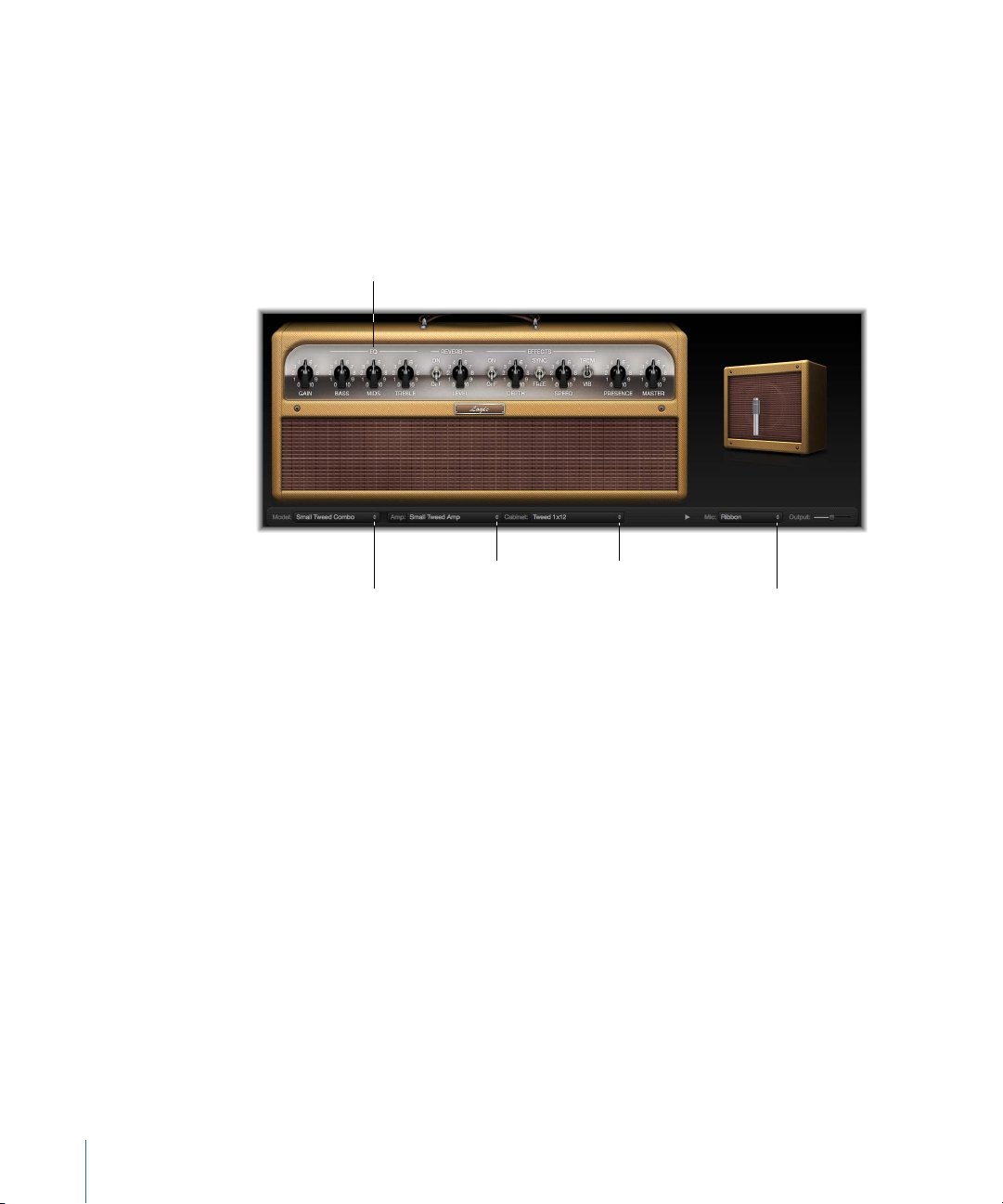
Page 24
Despite these less pleasant-sounding possibilities, you should experiment with different
Bass, Mids, and Treble
knobs
EQ pop-up menu
amplifier and EQ combinations because many will sound great together.
The EQ parameters include the EQ pop-up menu and the Bass, Mids, and Treble knobs.
These parameters are found toward the left-end of the knobs section.
• EQ pop-up menu: Click the word EQ or CUSTOM EQ above the Bass, Mids, and Treble
knobs to open the EQ pop-up menu, which contains the following EQ models: British
Bright, Vintage, U.S. Classic, Modern, and Boutique. Each EQ model has unique tonal
qualities that affect the way the Bass, Mids, and Treble knobs respond. See Amp Designer
Equalizer Type Reference Table.
• Bass, Mids, and Treble knobs: Adjust the frequency ranges of the EQ models, similar to
the tone knobs on a hardware guitar amplifier. The behavior and response of these
knobs changes when different EQ models are chosen.
Amp Designer Equalizer Type Reference Table
You can choose an Equalizer type by clicking the word EQ or CUSTOM EQ above the Bass,
Mids, and Treble knobs in the knobs section. The table below covers the properties of
each EQ type available in Amp Designer.
British Bright
24 Chapter 1 Amps and Pedals
Vintage
U.S. Classic
DescriptionEQ type
Inspired by the EQ of British combo amps of the 1960s. It is loud
and aggressive, with even bolder highs than the Vintage EQ. This
EQ is useful if you want more treble definition without an overly
clean sound.
Emulates the EQ response of American Tweed-style amps and the
vintage British stack amps that used a very similar circuit. It is loud
and somewhat distortion-prone. This EQ is useful if you want to
roughen the sound.
Derived from the EQ circuit of the American Blackface-style amps.
The tone is of higher fidelity than the Vintage EQ, with tighter lows
and crisper highs. This EQ is useful if you want to brighten your
tone and reduce distortion.
Page 25
DescriptionEQ type
Gain
Presence Master
Modern
Boutique
Based on a digital EQ unit popular in the 1980s and 1990s. This EQ
is useful for sculpting the hyped highs, booming lows, and scooped
mids associated with the era’s rock and metal music styles.
Replicates the tone section of a “retro modern” boutique amp. It
excels at precise EQ adjustments, though its tone may be cleaner
than desired when used with vintage amplifiers. This EQ is a good
choice if you want a cleaner, brighter sound.
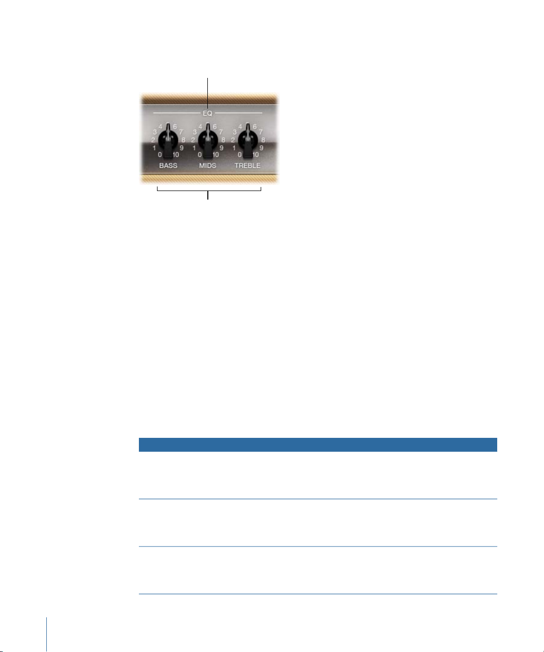
Using Amp Designer’s Gain, Presence, and Master Controls
The amp parameters include controls for the input gain, presence, and master output.
The Gain knob is found to the left in the knobs section and the Presence and Master
knobs are to the right.
• Gain knob: Sets the amount of pre-amplification applied to the input signal. This control
affects various amp models differently. For example, when you are using the British
Amp, the maximum gain setting produces a powerful crunch sound. When you are
using the Vintage British Head or Modern British Head, the same gain setting produces
heavy distortion, suitable for lead solos.
• Presence knob: Adjusts the high-frequency range—above the range of the Treble
control. The Presence parameter affects only the output (Master) stage.
• Master knob: Sets the output volume of the amplifier going to the cabinet. For tube
amplifiers, increasing the Master level typically produces a somewhat compressed and
saturated sound, resulting in a more distorted and powerful—that is, louder—signal.
High Master settings can produce an extremely loud output that can damage your
speakers or hearing, so ramp this up slowly. The final output level of Amp Designer is
set with the Output slider at the lower-right edge of the interface. See Setting Amp
Designer’s Output Level.
25Chapter 1 Amps and Pedals
Page 26
Getting to Know Amp Designer’s Effects Parameters
The effects parameters include Tremolo, Vibrato, and Reverb, which emulate the processors
found on many amplifiers. these controls are found in the center of the knobs section.
You can use the switch toward the right to select either Tremolo (TREM), which modulates
the amplitude or volume of the sound, or Vibrato (VIB), which modulates the pitch.
Reverb, which is controlled by a switch in the middle, can be added to either of these
effects, or used independently.
Note: The Effects section is placed before the Presence and Master controls in the signal
flow, and receives the pre-amplified, pre-Master signal.
Reverb, Tremolo, and Vibrato are described in the following sections:
• Using Amp Designer’s Reverb Effect
• Using Amp Designer’s Tremolo and Vibrato Effects
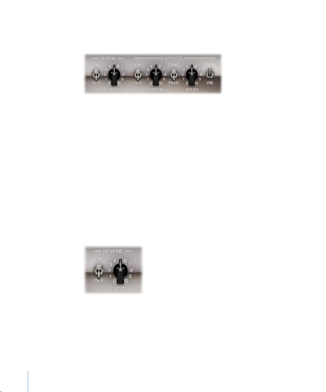
Using Amp Designer’s Reverb Effect
Reverb is always available in Amp Designer, even when using a model that is based on
an amplifier that provides no reverb function. Reverb is controlled by an On/Off switch
and a Level knob in the middle, above which is the Reverb pop-up menu. Reverb can be
added to either the Tremolo or Vibrato effect, or used independently.
• On/Off switch: Enables or disables the reverb effect.
• Reverb pop-up menu: Click the word Reverb to choose one of the following reverb types
from the pop-up menu: Vintage Spring, Simple Spring, Mellow Spring, Bright Spring,
Dark Spring, Resonant Spring, Boutique Spring, Sweet Reverb, Rich Reverb, and Warm
Reverb. See Amp Designer Reverb Type Reference Table for information on these reverb
types.
26 Chapter 1 Amps and Pedals
Page 27
• Level knob: Sets the amount of reverb applied to the pre-amplified signal.
Amp Designer Reverb Type Reference Table
You can choose a reverb type by clicking the Reverb label in the center of the Amp section.
The table below covers the properties of each reverb type available in Amp Designer.
DescriptionReverb type
Vintage Spring
Bright Spring
Resonant Spring
Boutique Spring
This bright, splashy sound has largely defined combo amp reverb
since the early 1960s.
A darker, subtler spring sound.Simple Spring
An even darker, somewhat low-fidelity spring sound.Mellow Spring
Has some of the brilliance of Vintage Spring, but with less surf-style
splash.
A moody-sounding spring. More restrained than Mellow Spring.Dark Spring
Another 1960s-style spring with a strong, slightly distorted
mid-range emphasis.
A modernized version of the classic Vintage Spring with a richer
tone in the bass and mids.
A smooth modern reverb with rich lows and restrained highs.Sweet Reverb
A bold, well-balanced modern reverb.Rich Reverb
A lush modern reverb with rich low-mids and understated highs.Warm Reverb
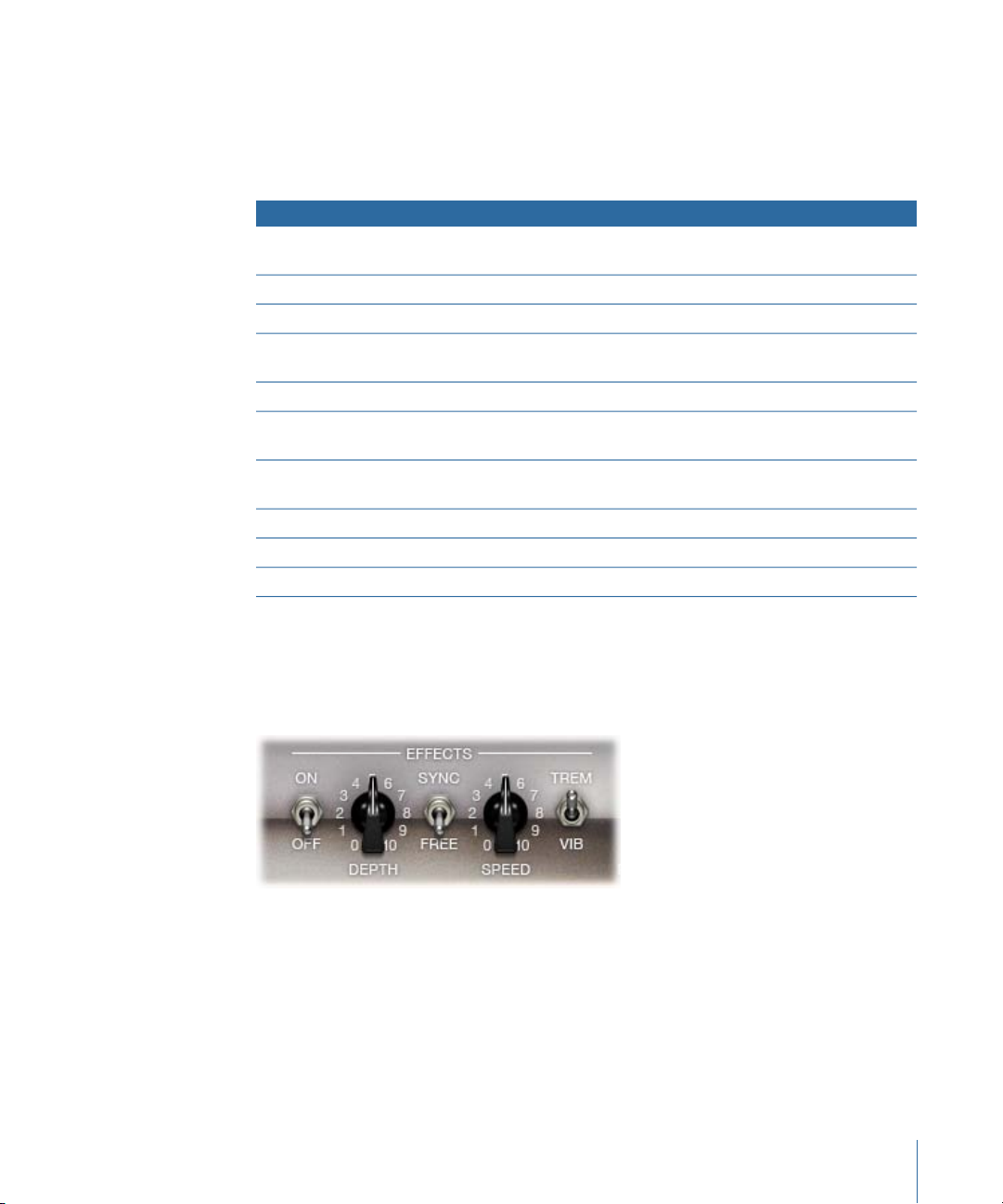
Using Amp Designer’s Tremolo and Vibrato Effects
Tremolo and vibrato are controlled by several switches and two knobs in the Effects
section found toward the right of the knobs section. Tremolo modulates the amplitude
or volume of the sound, and vibrato modulates the pitch.
• On/Off switch: Enables or disables the tremolo or vibrato effect.
• Trem/Vib switch: Choose either tremolo or vibrato.
• Depth knob: Sets the intensity of the modulation (tremolo or vibrato).
• Speed knob: Sets the speed of the modulation in Hertz. Lower settings produce a
smooth, floating sound. Higher settings produce a rotor-like effect.
27Chapter 1 Amps and Pedals
Page 28
• Sync/Freeswitch: When the switch is set to Sync, the modulation speed is synchronized
Move your mouse
above the Mic pop-up
menu to display the
speaker-adjustment
graphic.
with the host application tempo. The Speed knob lets you select different bar, beat,
and musical note values (1/8, 1/16, and so on, including triplet and dotted-note values).
When the switch is set to Free, the modulation speed can be set to any available value
with the Speed knob.
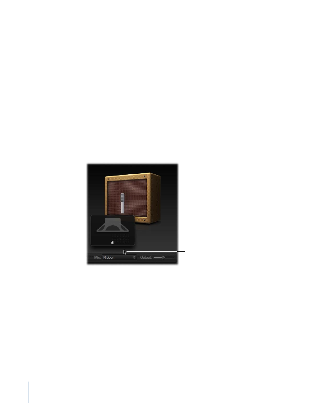
Setting Amp Designer Microphone Parameters
Amp Designer offers a choice between three different virtual microphones. As with every
other component in the tone chain, different selections yield very different results. After
choosing a cabinet, you can set the type of microphone you want to be emulated, and
where the microphone is placed in relation to the cabinet. The Mic pop-up menu is
available near the right end of the black bar at the bottom, and the speaker-adjustment
graphic appears when you move your mouse to the area above the Mic pop-up menu.
Note: The parameters described in this section are accessible only in the full Amp Designer
interface. If you are in the small interface, click the disclosure triangle to the right of the
Output field at the bottom-right edge of the interface to switch back to the full interface.
• Cabinet and speaker-adjustment graphic: By default, the microphone is placed in the
center of the speaker cone (on-axis). This placement produces a fuller, more powerful
sound, suitable for blues or jazz guitar tones. If you place the microphone on the rim
of the speaker (off-axis), you obtain a brighter, thinner tone, making it suitable for
cutting rock or R & B guitar parts. Moving the microphone closer to the speaker
emphasizes bass response.
The microphone position is shown on the cabinet and indicated by the white dot in
the speaker-adjustment graphic. Drag the whitedot to change the microphone position
and distance, relative to the cabinet. Placement is limited to near-field positioning.
28 Chapter 1 Amps and Pedals
Page 29

• Mic pop-up menu: You can choose one of the Microphone models from the pop-up
menu:
• Condenser: Emulates the sound of a high-endGerman studio condenser microphone.
The sound of condenser microphones is fine, transparent, and well-balanced.
• Dynamic: Emulates the sound of popular American dynamic cardioid microphones.
This microphone type sounds brighter and more cutting than the Condenser model.
The mid-rangeis boosted, with lower-mid frequencies being less pronounced, making
it a good choice for miking rock guitar tones. It is especially useful if you want your
guitar part to cut through other tracks in a mix.
• Ribbon: Emulates the sound of a ribbon microphone. A ribbon microphone is a type
of dynamic microphone that captures a sound often described as bright or brittle,
yet still warm. It is useful for rock, crunch, and clean tones.
Tip: Combining multiple microphone types can produce an interesting sound. Duplicate
the guitar track, and insert Amp Designer on both tracks. Select different microphones
in each Amp Designer instance while retaining identical settings for all other parameters,
and set track signal levels to taste.
Setting Amp Designer’s Output Level
The Output slider (or the Output field, in the small interface) is found at the lower-right
corner of the Amp Designer interface. It serves as the final level control for Amp Designer
and can be thought of as a “behind the speaker” volume control that sets the level of the
output that is fed to the ensuing Insert slots in the channel strip, or directly to the channel
strip output.
Note: This parameter is different from the Master control, which serves the dual purpose
of sound design as well as controlling the level of the Amp section.
29Chapter 1 Amps and Pedals
Page 30
Bass Amp
Bass Amp simulates the sound of several famous bass amplifiers. You can route bass
guitar and other signals directly through the Bass Amp, reproducing the sound of your
musical part played through a number of high-quality bass guitar amplification systems.
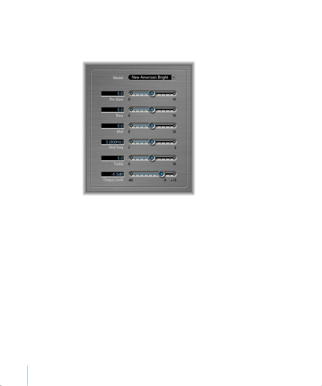
Bass Amp offers the following parameters.
• Model pop-up menu: Includes the following amplifier models:
• American Basic: 1970s-era American bass amp, equipped with eight 10" speakers.
Well-suited for blues and rock recordings.
• American Deep: Based on the American Basic amp, but with strong lower-mid
frequency (from 500 Hz on) emphasis. Well-suited for reggae and pop recordings.
• American Scoop: Based on the American Basic amp, but combines the frequency
characteristics of the American Deep and American Bright, with both low-mid (from
500 Hz) and upper-mid (from 4.5 kHz) frequencies emphasized. Well-suited for funk
and fusion recordings.
• American Bright: Based on the American Basic amp, this model emphasizes the
upper-mid frequencies (from 4.5 kHz upward).
• New American Basic: 1980s-era American bass amp, well-suited for blues and rock
recordings.
• New American Bright: Based on the New American Basic amp, this model strongly
emphasizes the frequency range above 2 kHz. Well-suited for rock and heavy metal.
30 Chapter 1 Amps and Pedals
Page 31

• Top Class DI Warm: Famous DI box simulation, well-suited for reggae and pop
recordings. Mid frequencies, in the range between 500 and 5000 Hz, are
de-emphasized.
• TopClass DI Deep: Based on the Top Class DI Warm, this model is well-suited for funk
and fusion. The mid frequency range is strongest around 700 Hz.
• Top Class DI Mid: Based on the Top Class DI Warm, this model features an almost
linear frequency range, with no frequencies emphasized. It is suitable for blues, rock,
and jazz recordings.
• Pre Gain slider: Sets the pre-amplification level of the input signal.
• Bass, Mid, and Treble sliders: Adjusts the bass, mid, and treble levels.
• Mid Freq slider: Sets the center frequency of the mid band (between 200 Hz and 3000 Hz).
• Output Level slider: Sets the final output level for Bass Amp.
Guitar Amp Pro
Guitar Amp Pro can simulate the sound of popular guitar amplifiers and the speakers
used with them. You can process guitar signals directly, which enables you to reproduce
the sound of your guitar through a number of high-quality guitar amplification systems.
Guitar Amp Pro can also be used for experimental sound design and processing. You can
freely use it with other instruments, applying the sonic character of a guitar amp to a
trumpet or vocal part, for example.
The amplifier, speaker, and EQ models emulated by Guitar Amp Pro can be combined in
a number of ways to radically or subtly alter the tone. Virtual microphones are used to
pick up the signal of the emulated amplifier and cabinet. You can choose from two
different microphone types, and you can reposition them. Guitar Amp Pro also emulates
classic guitar amplifier effects, including reverb, vibrato, and tremolo.
31Chapter 1 Amps and Pedals
Page 32

The Guitar Amp Pro window is organized into sections according to different kinds of
Effects section
Amp section
Microphone Position section Microphone Type section
parameters.
• Amp section: The model parameters at the top are used to choose the type of amp,
EQ model, and speaker. See Building Your Guitar Amp Pro Model.
Farther down in the Amp section, the knobs in the V-shaped formation are used to set
tone, gain, and level. See Using Guitar Amp Pro’s Gain, Tone, Presence, and Master
Controls.
• Effects section: Provides parameters to control the built-in tremolo, vibrato, and reverb
effects. See Using Guitar Amp Pro’s Reverb Effect and Using Guitar Amp Pro’s Tremolo
and Vibrato Effects.
• Microphone Position and Type sections: These sections enable you to set the position
and type of the microphone. See Setting Guitar Amp Pro Microphone Parameters.
Building Your Guitar Amp Pro Model
An amplifier “model” consists of an amplifier, speaker cabinet, EQ type, and microphone
type. You can create your own hybrids of different amplifiers, cabinets, and so on—using
the pop-up menus at the top center of the interface. You choose the microphone position
and type in the yellow areas to the left and right.
You can use the Settings menu to save your new hybrid amp combos as setting files,
which also include any parameter changes you may have made.
How to build your amplifier model is described in the following sections:
• Choosing a Guitar Amp Pro Amplifier
• Choosing a Guitar Amp Pro Speaker Cabinet
32 Chapter 1 Amps and Pedals
Page 33

• Choosing a Guitar Amp Pro Equalizer
• Setting Guitar Amp Pro Microphone Parameters
Choosing a Guitar Amp Pro Amplifier
You can choose an amplifier model from the Amp pop-up menu near the top of the
interface.
• UK Combo 30W: Neutral-sounding amp, well-suited for clean or crunchy rhythm parts.
• UK Top 50W: Quite aggressive in the high frequency range, well-suited for classical rock
sounds.
• US Combo 40W: Clean sounding amp model, well-suited for funk and jazz sounds.
• US Hot Combo 40W: Emphasizes the high mid-frequency range, making this model
ideal for solo sounds.
• US Hot Top 100W: This amp produces very fat sounds, even at low Master settings, that
result in broad sounds with a lot of “oomph.”
• Custom 50W: With the Presence parameter set to 0, this amp model is well-suited for
smooth fusion lead sounds.
• British Clean (GarageBand): Simulates the classic British Class A combos used
continuously since the 1960s for rock music, without any significant modification. This
model is ideally suited for clean or crunchy rhythm parts.
• British Gain(GarageBand): Emulates the sound of a British tube head and is synonymous
with rocking, powerful rhythm parts and lead guitars with a rich sustain.
• American Clean(GarageBand): Emulates the traditional full tube combos used for clean
and crunchy sounds.
• American Gain (GarageBand): Emulates a modern Hi-Gain head, making it suitable for
distorted rhythm and lead parts.
• Clean Tube Amp: Emulates a tube amp model with very low gain (distortion only when
using very high input levels or Gain/Master settings).
Choosing a Guitar Amp Pro Speaker Cabinet
The speaker cabinet can have a huge bearing on the type of tones you can extract from
your chosen amplifier. The speaker parameters are found near the top of the interface.
• Speaker pop-up menu: You can choose one of the 15 speaker models:
• UK 1 x 12 open back: Classic open enclosure with one 12" speaker, neutral,
well-balanced, multifunctional.
• UK 2 x 12 open back: Classic open enclosure with two 12" speakers, neutral,
well-balanced, multifunctional.
• UK 2 x 12 closed: Loads of resonance in the low frequency range, therefore well-suited
for Combos: crunchy sounds are also possible with low Bass control settings.
33Chapter 1 Amps and Pedals
Page 34

• UK 4 x 12 closed slanted: when used in combination with off-center miking, you will
get an interesting mid frequency range; therefore, this model works well when
combined with High Gain amps.
• US 1 x 10 open back: Not much resonance in the low frequency range. Suitable for
use with blues harmonicas.
• US 1 x 12 open back 1: Open enclosure of an American lead combo with a single 12"
speaker.
• US 1 x 12 open back 2: Open enclosure of an American clean/crunch combo with a
single 12" speaker.
• US 1 x 12 open back 3: Open enclosure of another American clean/crunch combo
with a single 12" speaker.
• US broad range: Simulation of a classic electric piano speaker.
• Analog simulation: Internal speaker simulation of a well-known British tube
preamplifier.
• UK 1 x 12 (GarageBand): A British Class A tube open back with a single 12" speaker.
• UK 4 x 12 (GarageBand): Classic closed enclosure with four 12" speakers (black series),
suitable for rock.
• US 1 x 12 open back (GarageBand): Open enclosure of an American lead combo with
a single 12" speaker.
• US 1 x 12 bass reflex (GarageBand): Closed bass reflex cabinet with a single 12" speaker.
• DI Box: This option allows you to bypass the speaker simulation section.
• Amp-Speaker Linkbutton: Located between the Amp and Speaker pop-up menus, links
these pop-up menus so that when you change the amp model, the speaker associated
with that amp is loaded automatically.
Choosing a Guitar Amp Pro Equalizer
The EQ pop-up menu and the Amp-EQ Link button are near the top of the interface.
• EQ pop-up menu: Contains the following EQ models: British1, British2, American, and
Modern. Each EQ model has unique tonal qualities that affect the way the Bass, Mids,
and Treble knobs in the Amp section respond.
• Amp-EQ Link button: Located between the Amp and EQ pop-up menus, links these
pop-up menus so that when you change the amp model, the EQ model associated
with that amp is loaded automatically.
Each amp model has a speaker and EQ model associated with it. The default
combinations of amp, speaker, and EQ settings recreate a well-known guitar sound.
You are, of course, free to combine any speaker or EQ model with any amp by turning
off the two Link buttons.
34 Chapter 1 Amps and Pedals
Page 35

Using Guitar Amp Pro’s Gain, Tone, Presence, and Master Controls
The Gain, Bass, Mids, Treble, Presence, and Master knobs run from left to right in the
V-shaped formation in the upper half of the interface.
• Gain knob: Sets the amount of pre-amplification applied to the input signal. This control
has different effects, depending on which Amp model is chosen. For example, when
you are using the British Clean amp model, the maximum Gain setting produces a
powerful crunch sound. If you use the British Gain or Modern Gain amps, the same
Gain setting produces heavy distortion, suitable for lead solos.
• Bass, Mids, and Treble knobs: Adjust the frequency range levels of the EQ models, similar
to the tone knobs on a hardware guitar amplifier.
• Presence knob: Adjusts the high frequency range level. The Presence parameter affects
only the output (Master) stage of Guitar Amp Pro.
• Master knob: Sets the output volume of the amplifier—going to the speaker. For tube
amplifiers, increasing the Master level typically produces a more compressed and
saturated sound, resulting in a more distorted and powerful—that is, louder—signal.
High Master settings can produce an extremely loud output that can damage your
speakers or hearing, so ramp this up slowly. In Guitar Amp Pro, the Master parameter
modifies the sonic character, and the final output level is set using the Output parameter
at the bottom of the interface. See Setting the Guitar Amp Pro Output Level.
Getting to Know Guitar Amp Pro’s Effects Section
The effects parameters include Tremolo, Vibrato, and Reverb, which emulate the processors
found on many amplifiers.
You can use the pop-up menu to choose either Tremolo, which modulates the amplitude
or volume of the sound, or Vibrato, which modulates the pitch.
Reverb can be added to either of these effects, or used independently.
To use or adjust an effect, you must first enable it by clicking the corresponding On button
to the left. The On button is red when active.
Note: The Effects section is placed before the Presence and Master controls in the signal
flow, and receives the preamplified, pre-Master signal.
Tremolo, Vibrato, and Reverb are described in the following sections:
• Using Guitar Amp Pro’s Tremolo and Vibrato Effects
• Using Guitar Amp Pro’s Reverb Effect
35Chapter 1 Amps and Pedals
Page 36

Using Guitar Amp Pro’s Tremolo and Vibrato Effects
Tremolo and vibrato are controlled by an On button, the FX pop-up menu, the Depth
and Speed knobs, and the Sync button in the Effects section. Tremolo modulates the
amplitude or volume of the sound, and vibrato modulates the pitch.
• FX pop-up menu: You can choose either Tremolo or Vibrato.
• Depth knob: Sets the intensity of the modulation.
• Speed knob: Sets the speed of the modulation in Hertz. Lower settings producea smooth
and floating sound, while higher settings produce a rotor-like effect.
• Sync button: When the Sync button is turned on, the modulation speed is synchronized
to the project tempo. You can adjust the Speed knob to select bar, beat, and musical
note values (including triplet and dotted notes). When the Sync button is turned off,
the modulation speed can be set to any available value with the Speed knob.
Using Guitar Amp Pro’s Reverb Effect
Reverb is controlled by an On button, the Reverb pop-up menu, and a Level knob in the
Reverb section near the bottom. Reverb can be added to either the Tremolo or Vibrato
effect, or used independently.
• Reverb pop-up menu: Choose one of the three types of spring reverb.
• Level knob: Sets the amount of reverb applied to the pre-amplified amp signal.
Setting Guitar Amp Pro Microphone Parameters
After choosing a speaker cabinet from the Speaker menu, you can set the type of
microphone you want to be emulated, and where the microphone is placed in relation
to the speaker. The Microphone Position parameters are available in the yellow area to
the left, and the Microphone Type parameters in the yellow area to the right.
Microphone Position Parameters
• Centered button: Places the microphone in the center of the speaker cone, also called
on-axis. This placement produces a fuller, more powerful sound, suitable for blues or
jazz guitar tones.
• Off-Center button: Places the microphone on the edge of the speaker, also referred to
as off-axis. This placement produces a tone that is brighter and sharper, but also
thinner—suitable for cutting rock or R & B guitar parts.
When you select either button, the graphic speaker display reflects your choice.
Microphone Type Parameters
• Condenser button: Emulates the sound of a studio condenser microphone. The sound
of condenser microphones is fine, transparent, and well-balanced.
36 Chapter 1 Amps and Pedals
Page 37

• Dynamic button: Emulates the sound of a dynamic cardioid microphone. This
microphone type sounds brighter and more cutting than the Condenser model. At the
same time, the lower-mid frequency range is less pronounced, making this model more
suitable for miking rock guitar tones.
Tip: Combining both microphone types can sound quite interesting. Duplicate the
guitar track, and insert Guitar Amp Pro as an insert effect on both tracks. Select different
microphone types in each Guitar Amp Pro instance, while retaining identical settings
for all other parameters, and mix the track signal levels. You can, of course, choose to
vary any other parameters.
Setting the Guitar Amp Pro Output Level
The Output slider is found at the bottom, below the Effects section. It serves as the final
level control for Guitar Amp Pro and can be thought of as a “behind the speaker” volume
control that is used to set the level fed to the ensuing plug-in slots on the channel strip
or to Output channel strips.
Note: This parameter is different from the Master control, which serves the dual purpose
of sound design as well as controlling the level of the Amp section.
Pedalboard
The Pedalboard simulates the sound of a number of well-loved and famous “stompbox”
pedal effects. You can process any audio signal with a combination of stompboxes.
You can add, remove, and reorder pedals. The signal flow runs from left to right in the
Pedal area. The addition of two discrete busses, coupled with splitter and mixer units,
enables you to experiment with sound design and precisely control the signal at any
point in the signal chain.
37Chapter 1 Amps and Pedals
Page 38

Macro Controls area
Pedal Browser
Pedal area
Routing area
All stompbox knobs, switches, and sliders can be automated. Eight Macro controls enable
real time changes to any pedal parameter with a MIDI controller.
• The Pedal Browser shows all pedal effects and utilities. These can be dragged into the
Pedal area as part of the signal chain. See Using Pedalboard’s Pedal Browser. This
interface area is also used for the alternative import mode. See Using Pedalboard’s
Import Mode.
• The Pedal area is where you determine the order of effects and set effect parameters.
You can add, replace, and remove stompboxes here. See Using Pedalboard’s Pedal
Area.
• The Routing area is used to control signal flow in the two effects busses (Bus A and
Bus B) available in Pedalboard. See Using Pedalboard’s Routing Area.
• The Macro Controls area is used to assign eight MIDI controllers, which can be used to
control any stompbox parameter in real time. See Using Pedalboard’s Macro Controls
Area.
• The effect and utility pedals are described in the following sections:
• Distortion Pedals
• Modulation Pedals
• Delay Pedals
• Filter Pedals
• Dynamics Pedals
• Utility Pedals
38 Chapter 1 Amps and Pedals
Page 39

Using Pedalboard’s Pedal Browser
View pop-up menu
Import Mode button
Pedalboard offers dozens of pedal effects and utilities in the Pedal Browser on the right
side of the interface. Each effect and utility is grouped into a category, such as distortion,
modulation, and so on. For information about these types of stompboxes, see Distortion
Pedals, Modulation Pedals, Delay Pedals, Filter Pedals, Dynamics Pedals, and Utility Pedals.
To hide or show the Pedal Browser
Click the disclosure triangle in the lower-right corner of the Pedal area.
µ
To show only specific pedal groups in the Pedal Browser
Open the View pop-up menu and choose Distortion, Modulation, Delay, Filter, Dynamics,
µ
or Utility. The Pedal Browser shows only the stompboxes within the category you choose.
To show all the pedal groups, choose Show All from the View pop-up menu.
To add a stompbox to the Pedal area
Do one of the following:
Drag the effect that you want to insert from the Pedal Browser to the appropriate Pedal
µ
area position. This can be to the left, to the right, or in-between existing pedals.
Double-click an effect in the Pedal Browser to add it to the right of all existing stompboxes
µ
in the Pedal area.
39Chapter 1 Amps and Pedals
Page 40

Note: Double-clicking a stompbox in the Pedal Browser when a stompbox is selected in
the Pedal area will replace the selected pedal.
Using Pedalboard’s Import Mode
Pedalboard has a feature you can useto import parameter settingsfor each type ofpedal.
In contrast to the plug-in window Settings menu, which you use to load a setting for the
entire Pedalboard plug-in, this feature can be used to load a setting for a specific stompbox
type.
To activate or deactivate import mode
Click the Import Mode button to show all pedals used in the most recent Pedalboard
µ
setting. When the Import Mode button is active,the Pedal Browser switches to analternate
view mode that displays imported settings. When import mode is inactive, the normal
Pedal Browser view is shown.
To import pedal settings into the Pedal Browser
1 Click the Import Mode button to activate import mode. Note thatthe View menu changes
to the Select Setting button.
Note: If this is your first attempt to import settings, a dialog opens where you can select
a setting to import.
40 Chapter 1 Amps and Pedals
Page 41

2 Click the Select Setting button and select a setting, then click Open. Dependent on the
chosen setting, one or more stompboxes appear in the Pedal Browser. The name of the
imported setting is shown at the bottom of the Pedal Browser.
To add an imported pedal to the Pedal area
Do one of the following:
Drag the stompbox that you want to add from the Pedal Browser to the appropriate
µ
Pedal area position. This can be to the left, to the right, or in-between existing pedals.
Ensure that no pedal is selected in the Pedal area, then double-click a stompbox in the
µ
Pedal Browser to add it to the right of all existing effects in the Pedal area.
Note: The parameter settings of pedals added in import mode are also imported.
To replace a pedal setting in the Pedal area with an imported pedal setting
1 Click the pedal you want to replace in the Pedal area. It becomes highlighted with a blue
outline.
2 Click the stompbox in the Pedal Browser to replace the selected pedal (or pedal setting)
in the Pedal area. The blue outlines of the selected pedal in the Pedal area and Pedal
Browser blink on and off to indicate an imported setting. The setting name area at the
bottom of the Pedal Browser displays “Click selected item again to revert.”
Note: If you want to make your replacement permanent, click the background in the
Pedal Browser, or click the Import Mode button.
3 To restore the selected pedal’s previous setting, click the highlighted stompbox in the
Pedal Browser. The Import Mode button and the outline of the selected pedal (in the
Pedal area) become solidly highlighted, indicating that the original setting has been
restored.
Using Pedalboard’s Pedal Area
Pedalboard’s stompbox effect pedals not only resemble their physical counterparts; they
are also used in much the same way—without the inconvenience of patch cords, power
supplies, and screws or locking mechanisms. The Pedal area layout mirrors a traditional
pedalboard, with signals running from left to right.
41Chapter 1 Amps and Pedals
Page 42

To add a pedal to the Pedal area
Do one of the following:
Drag the stompbox that you want to insert from the Pedal Browser to the appropriate
µ
Pedal area position. This can be to the left, to the right, or in-between existing pedals.
Ensure that no pedal is selected in the Pedal area, then double-click a stompbox in the
µ
Pedal Browser to add it to the right of all existing effects in the Pedal area.
Note: You insert Mixer and Splitter utility pedals in a different way. See Using Pedalboard’s
Routing Area.
To change an effect pedal position in the Pedal area
Drag the stompbox to a new position, either to the right or the left. Automation and bus
µ
routings, if active, are moved with the effect pedal. For information about automation
and bus routings, see Using Pedalboard’s Routing Area.
Note: There are two exceptions to the bus routing rule: If the dragged pedal is the only
pedal between a Splitter and Mixer utility, both utility pedals are automatically removed.
If the second Bus (“B”) is not active at the destination, the pedal is inserted into Bus A.
To change a Mixer utility position in the Pedal area
Drag the Mixer utility to a new position, either to the left or the right.
µ
When moved to the left: The “downmix” of Bus A and B will occur at the earlier insertion
point. Relevant effect pedals are moved to the right and are inserted into Bus A.
When moved to the right: The “downmix” of Bus A and B will occur at the later insertion
point. Relevant effect pedals are moved to the left and are inserted into Bus A.
Note: A Mixer pedal cannot be moved to a position directly after (or to the left of) a
corresponding split point or Splitter utility.
To change a Splitter utility position in the Pedal area
Drag the Splitter utility to a new position, either to the right or the left.
µ
When moved to the left: The split between Bus A and B will occur at the earlier insertion
point. Relevant effect pedals are moved to the right and are inserted into Bus A.
When moved to the right: The split between Bus A and B will occur at the later insertion
point. Relevant effect pedals are moved to the left and are inserted into Bus A.
Note: A Splitter pedal cannot be moved to a position directly preceding (or to the right
of) a corresponding Mixer utility.
To replace a pedal in the Pedal area
Do one of the following:
Drag the stompbox from the Pedal Browser directly over the pedal you want to replace
µ
in the Pedal area.
42 Chapter 1 Amps and Pedals
Page 43

Click to select the stompbox you want to replace in the Pedal area, then double-click the
µ
appropriate pedal in the Pedal Browser.
Note: You can only replace “effect” pedals, not the Mixer or Splitter utilities. Bus routings,
if active, are not changed when an effect pedal is replaced.
To remove a pedal from the Pedal area
Do one of the following:
Drag the pedal out of the Pedal area.
µ
Click the pedal to select it and press the Delete key.
µ
Using Pedalboard’s Routing Area
Pedalboard has two discrete signal buses—Bus A and Bus B—that are found in the Routing
area above the Pedal area. These busses provide a great deal of flexibility when you are
setting up signal processing chains. All stompboxes that you drag into the Pedal area are
inserted into Bus A, by default.
Note: The Routing area appears when you move your pointer to a position immediately
above the Pedal area, and it disappears when you move the pointer away. When you
create a second bus routing, the Routing area remains open even when your pointer is
not over it. You can close the Routing area by clicking the small latch button at the top,
and then the Routing area will open or close automatically when you move your pointer
over it.
To create a second bus routing
Do one of the following:
Move your pointer immediately above the Pedal area to open the Routing area, and click
µ
the name of a stompbox in the Routing area. The pedal name moves upward, and the
chosen stompbox is routed to Bus B. Two gray lines appear in the Routing area, which
represent Bus A and Bus B. A Mixer utility pedal is automatically added to the end of the
signal chain.
Drag a Splitter utility pedal into the Pedal area when more than one pedal is inserted.
µ
This also inserts a Mixer at the end of the signal chain if one doesn’t already exist.
To remove the second bus routing
Do one of the following:
Remove the Mixer and Splitter utility pedals from the Pedal area.
µ
43Chapter 1 Amps and Pedals
Page 44

Remove all stompboxes from the Pedal area. This automatically removes an existing Mixer
µ
utility.
To remove an effect from the second bus
Click the name of the pedal (or on either of the gray lines) in the Routing area.
µ
Note: The removal of all effects from Bus B does not remove the second bus. The Mixer
utility pedal remains in the Pedal area, even when a single stompbox (effect) is in the
Pedal area. This allows parallel routing of wet and dry signals. Only when all pedal effects
are removed from the Pedal area is the Mixer utility (and second bus) removed.
To determine the split point between busses
When more than one bus is active, a number of dots appear along the “cables” (gray
µ
lines) in the Routing area. These represent the output (the socket) of the pedal to the
lower left of the dot. Click the appropriate dotto determine where the split point—where
the signal is routed between busses. A cable appears between the busses when you click
a dot.
Note: You can not create a split point directly before, or after, the Mixer utility.
To switch between a Splitter utility and bus split point
Double-click a bus split point dot in the Routing area to replace it with a Splitter utility.
µ
The Splitter utility is shown in the Pedal area.
Double-click the Splitter label in the Routing area to replace the Splitter utility with a bus
µ
split point dot. The Splitter utility is removed from the Pedal area.
Notes on Splitter and Mixer Utility Use
Dragging a Splitter utility into the Pedal area automatically inserts a Mixer utility to the
far right of all inserted pedals.
You cannot drag a Splitter utility to the far right of all inserted pedals, to directly after
an inserted Splitter utility, to directly in front of an inserted Mixer utility, or to an empty
space in the Pedal area.
Dragging a Mixer utility into the Pedal area automatically creates a split point at the
earliest possible (the leftmost) point within the signal chain.
You cannot drag a Mixer utility to the first slot in the Pedal area, to between an inserted
Splitter and Mixer utility combo, or directly to the right of an inserted Mixer utility.
Using Pedalboard’s Macro Controls Area
Pedalboard provides eight Macro Targets—A through H—which are found in the Macro
Controls area below the Pedal area. These enable you to map any parameterof an inserted
stompbox as a Macro A–H target. You can save different mappings with each Pedalboard
setting.
44 Chapter 1 Amps and Pedals
Page 45

In Logic Express, you use a controller assignment or create a Workspace knob for “Macro
A–H Value.” MIDI hardware switches, sliders, or knobs can then be used to control the
mapped Pedalboard Macro A–H target parameters in real time. See the Logic Express
User Manual for details.
Click the triangle at the bottom left to hide or show the Macro Controls area.
• Macro A–H Target pop-up menus: Determine the parameter that you want to control
with a MIDI controller.
• Macro A–H Value sliders and fields: Set, and display, the current value for the parameter
chosen in the corresponding Macro Target pop-up menu.
To assign a Macro A–H Target
Do one of the following:
Click any of the Macro A–H Target pop-up menus, and choose the parameter that you
µ
want to control.
Each stompbox parameter is shown in the following way: “Slot number—Pedal
Name—Parameter”. As examples: “Slot 1—Blue Echo—Time”, or “Slot 2—Roswell
Ringer—Feedback”. The “slot” number refers to the pedal position, as they appear from
left to right in the Pedal area.
Choose the “-Auto assign-” item in any Macro A–H Target pop-up menu, then click the
µ
appropriate parameter in any inserted pedal.
Note: The chosen parameter is displayed in the Macro A–H Target pop-up menu.
Distortion Pedals
This section describes the distortion effects pedals.
DescriptionStompbox
Candy Fuzz
Double Dragon
A bright, “nasty” distortion effect. Drive controls the input signal
gain. Level sets the effect volume.
A deluxe distortion effect. It offers independent level controls for
input (Input) and output (Level). Drive controls the amount of
saturation applied to the input signal. The Tone knob sets the cutoff
frequency. The Squash knob sets the threshold for the internal
compression circuit.Contour sets the amount ofnonlinear distortion
applied to the signal. Mix sets the ratio between the source and
distorted signals. The Bright/Fat switch changes between two fixed
high shelving filter frequencies. Blue and red LEDs indicate each
switch position, respectively.
45Chapter 1 Amps and Pedals
Page 46

Fuzz Machine
Grinder
Happy Face Fuzz
Hi-Drive
Monster Fuzz
Octafuzz
Rawk! Distortion
Vintage Drive
DescriptionStompbox
An American “fuzz” distortion effect. Fuzz controls the input gain.
Overall output gain is set with Level. The Tone knob increases treble,
while simultaneously rolling-off low frequencies, as you move it to
higher values.
Grinder is a lo-fi, dirty “metal” distortion. Grind sets the amount of
drive applied to the input signal. Tone is controlled with the Filter
knob, making the sound harsher and more crunchy at higher values.
The Full/Scoop switch alternates between two fixed Gain/Q filter
settings. At the Full position, filtering is less pronounced than at
the Scoop position. Overall output level is controlled with the Level
knob.
A softer, full-sounding distortion effect. Fuzz sets the amount of
saturation applied to the input signal. Volumesets the output level.
An overdrive effect that can emphasize high frequency content in
the signal. Level controls the effect output. The Treble/Full switch
sets a fixed shelving frequency, allowing either the treble portion
or the full range input signal to be processed.
A saturated, somewhat harsh distortion. Roar sets the amount of
gain applied to the input signal. Growl setsthe amount of saturation.
Tone sets the overall color of the distortion. Higher Tone values
increase the treble content of the signal, but there is a
corresponding decrease in overall volume. Texture can smooth out
or roughen up the distortion. Grain sets the amount of nonlinear
distortion applied to the signal. The effect output is controlled with
the Level knob.
A fat fuzz effect, that can deliver a soft, saturated distortion. Fuzz
controls the input gain. Level sets the ratio between the distorted
and source signals. The Tone knob sets the cutoff frequency of the
highpass filter.
A metal/hard rock distortion effect. Crunch sets the amount of
saturation applied to the input signal. Output gain is set with Level.
Tonal color is set with the Tone knob, making the sound brighter
at higher values.
Overdrive effect that emulates the distortion produced by a field
effect transistor (FET), which is commonly used in solid-state
amplifiers. When saturated, FETs generate a warmer sounding
distortion than bipolar transistors (such as those emulated by
Grinder). Drivesets the saturation amount for the input signal. Tone
sets the frequency for the high cut filter, resulting in a softer or
harsher tone. The Fat switch, when at the top position, enhances
lower frequency content in the signal. Level sets the overall output
level of the effect.
Modulation Pedals
This section describes the modulation effects pedals.
46 Chapter 1 Amps and Pedals
Page 47

Heavenly Chorus
Phase Tripper
Phaze 2
Retro Chorus
Robo Flanger
DescriptionStompbox
A rich, sweet-sounding chorus effect that can significantly thicken
the sound. Rate sets the modulation speed and can run freely, or
be synchronized with the host application tempo by enabling the
Sync button. When synchronized, you can specify bar, beat and
note values (including triplets and dotted notes). Depth sets the
strength of the effect. Feedback sends the output of the effect back
in to the input, further thickening the sound, or leading to
intermodulations. Delay sets the ratio between the original and
effect signals. The upper Bright switch position applies a fixed
frequency internal EQ to the signal. At the bottom position, the EQ
is bypassed.
A simple phasing effect. Rate sets the modulation speed and can
run freely, or be synchronized with the host application tempo by
enabling the Sync button. When synchronized, you can specify bar,
beat and note values (including triplets and dotted notes). Depth
sets the strength of the effect. Feedback determines the amount
of the effect signal that is routed back into the input. This can
change the tonal color, can make the sweeping effect more
pronounced, or can do both.
A very flexible dual-phaser effect. LFO 1 and LFO2 Rate sets the
modulation speed and can run freely, or be synchronized with the
host application tempo by enabling the Sync button. Ceiling and
Floor determine the frequency range that is swept. Order switches
between different algorithms, with higher (even) numbers resulting
in a heavier phasing effect. Odd order numbers result in moresubtle
comb-filtering effects. Feedback determines the amount of the
effect signal that is routed back into the input. This can change the
tonal color, can make the phasing effect more pronounced, or can
do both. Tone works from the center position; turn it to the left to
increase the amount of lowpass filtering, or turn it to the right to
increase the amount of highpass filtering. Mix sets the level ratio
between each phaser.
A subtle,vintage chorus effect. Rate sets the modulation speed and
can run freely, or be synchronized with the host application tempo
by enabling the Sync button. When synchronized, you can specify
bar, beat and note values (including triplets and dotted notes).
Depth sets the strength of the effect.
Flexible flanging effect. Rate sets the modulation speed and can
run freely, or be synchronized with the host application tempo by
enabling the Sync button. When synchronized, you can specify bar,
beat and note values (including triplets and dotted notes). Depth
sets the strength of the effect. Feedback determines the amount
of the effect signal that is routed back into the input. This can
change the tonal color, can make the flanging effect more
pronounced, or can do both. The Manual knob sets a delay time
between the source and effect signals. This can result in
flanger-chorus effects, or in metallic-sounding modulations,
particularly when used with high Feedback values.
47Chapter 1 Amps and Pedals
Page 48

Roswell Ringer
Roto Phase
Spin Box
Total Tremolo
Trem-o-Tone
DescriptionStompbox
A ring modulation effect that can make incoming audio sound
metallic (or unrecognizable), can deliver tremolos, brighten up
signals and more. The Freq knob sets thecore filter cutoff frequency.
Fine is a fine tuning knob for the filter frequency. The Lin/Exp switch
determines if the frequency curve is linear (12 notes per octave) or
exponential. FB (feedback) determines the amount of the effect
signal that is routed back into the input. This can change the tonal
color, can make the effect more pronounced, or can do both.
Balance between the original and effect signals is set with the Mix
knob. See Ringshifter for background information on ring
modulation.
A phaser effect that adds movement to, and alters the phase of, the
signal. Rate sets the modulation speed and can run freely, or be
synchronized withthe host application tempo by enabling theSync
button. When synchronized, you can specify bar, beat and note
values (including triplets and dotted notes) with the Rate knob.
Intensity sets the strength of the effect. The Vintage/Modern switch
activates a fixed-frequency internal EQ when switched to Vintage,
and deactivates it when switched to Modern.
Emulation of a Leslie rotor speaker cabinet, commonly used with
the Hammond B3 organ. Cabinet sets the type of speaker box. Fast
Rate sets the maximum modulation speed (only applies when Fast
button is active). Response determines the amount of time required
for the rotor to reach its maximum and minimum speed. Drive
increases the input gain, introducing distortion to the signal. The
Bright switch activates a high shelving filter when turned on. The
Slow, Brake and Fast buttons determine how the “speaker”
behaves: Slow rotates the speaker slowly. Fast rotates the speaker
quickly (up to the maximum speed determined by the Fast Rate
knob). Brake stops the speaker rotation. See Rotor Cabinet Effect
for background information on the Leslie effect.
A flexible tremolo effect (modulation of the signal level). Rate sets
the modulation speed and can run freely, or be synchronized with
the host application tempo by enabling the Sync button. When
synchronized, you can specify bar, beat and note values (including
triplets and dotted notes). Depth sets the strength of the effect.
Wave and Smooth work in combination to alter the waveform shape
of the LFO. This enables you to create floating changes in level, or
abrupt steps. Volume determines the output level of the effect. The
1/2 and 2 x Speed buttons immediately halve or double the current
Rate value. Hold down the Speed Up and Slow Down buttons to
gradually accelerate or reduce the current Rate value to the
maximum or minimum possible values.
A tremolo effect (modulation of the signal level). Rate sets the
modulation speed and can run freely, or be synchronized with the
host application tempo by enabling the Sync button. When
synchronized, you can specify bar, beat and note values (including
triplets and dotted notes). Depth sets the strength of the effect.
Level sets the post-tremolo gain.
48 Chapter 1 Amps and Pedals
Page 49

DescriptionStompbox
the Vibe
A vibrato/chorus effect based on the Scanner Vibrato unit found in
the Hammond B3 organ. You can choose from three vibrato (V1–3)
or chorus (C1–3) variations with the Type knob. Rate sets the
modulation speed and can run freely, or be synchronized with the
host application tempo by enabling the Sync button. When
synchronized, you can specify bar, beat and note values (including
triplets and dotted notes). Depth sets the strength of the effect. See
Scanner Vibrato Effect for background information on this effect.
Delay Pedals
This section describes the Delay effects pedals.
DescriptionStompbox
Blue Echo
Spring Box
Tru-Tape Delay
A delay effect. Time sets the modulation speed and can run freely,
or be synchronized with the host application tempo by enabling
the Sync button. When synchronized, you can specify bar, beat and
note values (including triplets and dotted notes). The Repeats knob
determines the number of delay repeats. Mix sets the balance
between the delayed and source signals. The Tone Cut switch
controls afixed frequency internal filter circuit that allowsmore low
(Lo) or high (Hi)frequency contentto be heard. You can also disable
this filter circuit by choosing Off.
A spring reverb pedal. Time sets the length of the reverberation to
short, medium, or long values. Tone controls the cutoff frequency,
making the effect brighter or darker. Style switches between
algorithms, each with different characteristics. You can choose
from: Boutique, Simple, Vintage, Bright, and Resonant. Mix sets the
ratio between the source and effect signals.
A vintage tape delay effect. The Norm/Reverse switch changes the
delay playback direction. Reverse mode is indicated by a blue LED
and Normal mode is indicated by a red LED. Hi Cut and Lo Cut
activate a fixed frequency filter. Dirt sets the amount of input signal
gain, which can introduce an overdriven, saturated quality. Flutter
emulates speed fluctuations in the tape transport mechanism. Time
sets the modulation speed and can run freely, or be synchronized
with the host application tempoby enabling the Sync button.When
synchronized, you can specify bar, beat and note values (including
triplets and dotted notes). Feedback determines the amount of the
effect signal that is routed back into the input. The buildup of
repeating signals can be used creatively for dub-delay and other
effects by adjusting Feedback in real time. Mix sets the balance
between the source and effect signals.
Filter Pedals
This section describes the filter effects pedals.
49Chapter 1 Amps and Pedals
Page 50

DescriptionStompbox
Auto-Funk
Classic Wah
Modern Wah
An auto-wah (filter) effect. Sensitivity sets a threshold which
determines how the filter responds toincoming signal levels. Cutoff
sets the center frequency for the filter. The BP/LP switch enables
either a bandpass or lowpass filter circuit. Signal frequencies just
above and below the cutoff point are filtered when the BP switch
position is chosen. When the LP switch position is active, only signals
below the cutoff point are allowed through the filter. The Hi/Lo
switch chooses one of two preset (filter) resonance settings. The
Up/Down switch activates a positive or negative modulation
direction (the “wah” filtering occurs above or below the source
signal frequency).
A funky wah effect, straight from 1970’s TV police show soundtracks.
You control it by dragging the pedal.
A more aggressive wah effect. You control it by dragging the pedal.
Mode enables you to choose from the following: Retro Wah, Modern
Wah, Opto Wah 1, Opto Wah 2, Volume. Each has a different tonal
quality. The Q knob determines the resonant characteristics. Low Q
values affect a wider frequency range, resulting in softer resonances.
High Q values affect a narrower frequency range, resulting in more
pronounced emphasis.
Dynamics Pedals
This section describes the dynamics pedals.
DescriptionStompbox
Squash Compressor
A simple compressor. Sustainsets the threshold level. Signals above
this are reduced in level. Level determines the output gain. The
Attack switch can be set to Fast for signals withfast attack transients,
such as drums, or to Slow for signals with slow attack phases, such
as strings.
Utility Pedals
This section describes the parameters of the Mixer and Splitter pedals.
Mixer
50 Chapter 1 Amps and Pedals
DescriptionStompbox
A utility that is used to control the level relationship between Bus A
and Bus B signals. It can be inserted anywhere in the signal chain,
but is typically used at the end of the chain (at the extreme right
of the Pedal area). See Using Pedalboard’s Routing Area for details
on use. The A/Mix/B switch solos the “A” signal, mixes the “A” and
“B” signals, or solos the “B” signal. The level setting of the Mix fader
is relevant for all A/Mix/B switch positions.
In stereo instances, the Mixer utility also provides discrete Pan
controls for each bus.
Page 51

Splitter
DescriptionStompbox
A utility that can be inserted anywhere in the signal chain. Splitter
can be used in two ways;
When set to Freq, it works as a frequency-dependent signal splitter
that divides the incoming signal. Signals above the frequency set
with the Frequency knob are sent to Bus B. Signals below this
frequency are sent to Bus A.
When set to Split, the incoming signal is routed equally to both
buses. The Frequency knob has no impact in this mode.
See Using Pedalboard’s Routing Area for details on use.
51Chapter 1 Amps and Pedals
Page 52

Page 53

Delay Effects
2
Delay effects store the input signal—and hold it for a short time—before sending it to
the effect input or output.
The held, and delayed, signal is repeated after a given time period, creating a repeating
echo effect. Each subsequent repeat is a little quieter than the previous one. Most delays
also allow youto feed a percentage of thedelayed signal back to the input. This can result
in a subtle, chorus-like effect or cascading, chaotic audio output.
The delay time can often be synchronized to the project tempo by matching the grid
resolution of the project, usually in note values or milliseconds.
You can use delays to double individual sounds to resemble a group of instruments
playing the same melody, to create echo effects, to place the sound in a large “space”,
to generate rhythmic effects, or to enhance the stereo position of tracks in a mix.
Delay effects are generally used as channel insert or bussed effects. They are rarely used
on an overall mix (in an output channel), unless you’re trying to achieve an unusual effect.
This chapter covers the following:
• Echo (p. 54)
• Sample Delay (p. 54)
• Stereo Delay (p. 55)
• Tape Delay (p. 57)
53
Page 54

Echo
This simple echoeffect always synchronizes the delay time to the project tempo, allowing
you to quickly create echo effects that run in time with your composition.
• Time pop-upmenu: Sets the grid resolution of the delay time in musical note durations,
based on the project tempo.
• “T” values represent triplets.
• “.” values represent dotted notes.
• Repeat slider and field: Determines how often the delay effect is repeated.
• Color slider and field: Sets the harmonic content (color) of the delay signal.
• Dry and Wet sliders and fields: Control the amount of original and effect signal.
Sample Delay
Sample Delay is more a utility than an effect—you can use it to delay a channel by single
sample values.
When used in conjunction with the phase inversion capabilities of the Gain effect, Sample
Delay is useful for correction of timing problems that may occur with multichannel
microphones. It can also be used creatively, to emulate stereo microphone channel
separation.
54 Chapter 2 Delay Effects
Page 55

Every sample at a frequency of 44.1 kHz is equivalent to the time taken for a sound wave
to travel 7.76 millimeters. If you delay one channel of a stereo microphone by 13 samples,
this will emulate an acoustic (microphone) separation of 10 centimeters.
• Delay slider and field (L and R in stereo version): Determines the number of samples that
the incoming signal will be delayed by.
• Link L & R button (only in stereo version): Ensures that the number of samples is identical
for both channels. Adjusting one channel value will adjust the other.
Stereo Delay
The Stereo Delay works much like the Tape Delay (see Tape Delay), but allows you to set
the Delay, Feedback, and Mix parameters separately for the left and right channels. The
Crossfeed knob for each stereo side determines the feedback intensity or the level at
which each signal is routed to the opposite stereo side. You can freely use the Stereo
Delay on mono tracks or busses when you want to create independent delays for the
two stereo sides.
55Chapter 2 Delay Effects
Page 56

Note: If you use the effect on mono channel strips, the track or bus will have two channels
from the point of insertion—all Insert slots after the chosen slot will be stereo.
As the parameters for the left and right delays are identical, the descriptions below only
cover the left channel—the right channel information is provided in brackets, if named
differently. Parameters that are common to both channels are shown separately.
Channel Parameters
• Left (Right)Input pop-up menu: Choose the input signal for the two stereo sides. Options
include OFF, Left, Right, L + R, L − R.
• Left (Right) Delay field: Sets the current delay time in milliseconds (this parameter is
dimmed when you synchronize the delay time to the project tempo).
• Groove slider and field: Determines the proximity of every second delay repeat to the
absolute grid position—in other words, how close every second delay repeat is.
• Note buttons: Set the grid resolution for the delay time. These are shown as note
durations (these are dimmed when the delay time is not synchronized with the project
tempo).
• Left (Right) Feedback knob and field: Set the amount of feedback for the left and right
delay signals.
• Crossfeed Left toRight (Crossfeed Rightto Left)knob and field: Transfer the feedback signal
of the left channel to the right channel, and vice versa.
• FeedbackPhase button: Use to invert the phase of the corresponding channel’s feedback
signal.
• Crossfeed Phase button: Use to invert the phase of the crossfed feedback signals.
56 Chapter 2 Delay Effects
Page 57

Common Parameters
• Beat Sync button: Synchronizes delay repeats to the project tempo, including tempo
changes.
• Output Mix (Left and Right) sliders and fields: Independently control the left and right
channel signals.
• Low Cut and High Cut sliders and fields: Frequencies below the Low Cut value and above
the High Cut value are filtered out of the source signal.
Tape Delay
Tape Delay simulates the warm sound of vintage tape echo machines, with the
convenience of easy delay time synchronization to your project tempo. The effect is
equipped with a highpass and lowpass filter in the feedback loop, simplifying the creation
of authentic dub echo effects. Tape Delay also includes an LFO for delay time modulation,
which can be used to produce pleasant or unusual chorus effects, even on long delays.
• Feedback slider: Determines the amount of delayed and filtered signal that is routed
back to the input of the Tape Delay. Set the Feedback slider to the lowest possible
value to generate a single echo. Turn Feedback all the way up to endlessly repeat the
signal. The levels of the original signal and its taps (echo repeats) tend to accumulate,
and may cause distortion. You can use the internal tape saturation circuit to ensure
that these overdriven signals continue to sound good.
• Freeze button: Captures the current delay repeats and sustains them until the Freeze
button is turned off.
• Delay field: Sets the current delay time in milliseconds (this parameter is dimmed when
you synchronize the delay time to the project tempo).
• Sync button: Synchronizes delay repeatsto the project tempo(including tempo changes).
• Tempofield: Sets the current delay time in beats per minute (this parameter is dimmed
when you synchronize the delay time to the project tempo).
57Chapter 2 Delay Effects
Page 58

• Groove slider and field: Determines the proximity of every second delay repeat to the
absolute grid position—in other words, how close every second delay repeat is. A
Groove setting of 50% means that every delay has the same delay time. Settings below
50% result in every second delay being played earlier in time. Settings above 50% result
in every second delay being played later in time. When you want to create dotted note
values, move the Groove slider all the way to the right (to 75%). For triplets, select the
33.33% setting.
• Note buttons: Set the grid resolution for the delay time. These are shown as note
durations.
• Low Cut and High Cut sliders and fields: Frequencies below the Low Cut value and above
the High Cut value are filtered out of the source signal. You can shape the sound of
the echoes with the highpass and lowpass filters. The filters are located in the feedback
circuit, which means that the filtering effect increases in intensity with each delay
repeat. If you want an increasingly muddy and confused tone, move the High Cut slider
towards the left. For ever thinner echoes, move the Low Cut slider towards the right.
If you’re unable to hear the effect even though you seem to have a suitable
configuration, be sure to check out both the Dry and Wet controls and the filter
settings—move the High Cut slider to the far right, and the Low Cut slider to the far
left.
• Smooth slider and field: Evens out the LFO and flutter effect.
• LFO Rate knob and field: Sets the frequency of the LFO.
• LFO Depth knob andfield: Sets the amount of LFO modulation. A value of 0 turns delay
modulation off.
• Flutter Rate and Intensity sliders and fields: Simulate the speed irregularities of the tape
transports used in analog tape delay units.
• Flutter Rate: Sets the speed variation.
• Flutter Intensity: Determines how pronounced the effect is.
• Dry and Wet sliders and fields: Independently control the amount of original and effect
signal.
• Distortion Level slider and field (Extended Parameters area): Determines the level of the
distorted (tape saturation) signal.
58 Chapter 2 Delay Effects
Page 59

Distortion Effects
3
You can use Distortion effects to recreate the sound of analog or digital distortion and
to radically transform your audio.
Distortion effects simulate the distortion created by vacuum tubes, transistors, or digital
circuits. Vacuum tubes were used in audio amplifiers before the development of digital
audio technology, and they are still used in musical instrument amplifiers today. When
overdriven, they produce a type of distortion that many people find musically pleasing,
and which has become a familiar part of the sound of rock and pop music. Analog tube
distortion adds a distinctive warmth and bite to the signal.
There are also distortion effects that intentionally cause clipping and digital distortion of
the signal. These can be used to modify vocal, music, and other tracks to produce an
intense, unnatural effect, or to create sound effects.
Distortion effects include parameters for tone, which let you shape the way the distortion
alters the signal (often as a frequency-based filter), and for gain, which let you control
how much the distortion alters the output level of the signal.
Warning: When set to high output levels, distortion effects can damage your
hearing—and your speakers. When you adjust effect settings, it is recommended that
you lower the output level of the track, and raise the level gradually when you are
finished.
This chapter covers the following:
• Bitcrusher (p. 60)
• Clip Distortion (p. 61)
• Distortion Effect (p. 62)
• Distortion II (p. 63)
• Overdrive (p. 63)
• Phase Distortion (p. 64)
59
Page 60

Bitcrusher
Bitcrusher is a low-resolution digital distortion effect. You can use it to emulate the sound
of early digital audio devices, to create artificial aliasing by dividing the sample rate, or
to distort signals until they are unrecognizable.
• Drive slider and field: Sets the amount of gain in decibels applied to the input signal.
Note: Raising the Drive level tends to increase the amount of clipping at the output of
the Bitcrusher as well.
• Resolution slider and field: Sets the bit rate (between 1 and 24 bits). This alters the
calculation precision of the process. Lowering the value increases the number of
sampling errors, generating more distortion. At extremely low bit rates, the amount of
distortion can be greater than the level of the usable signal.
• Waveform display: Shows the impact of parameters on the distortion process.
• Downsampling sliderand field: Reduces the sample rate. A value of 1 x leaves the signal
unchanged, a value of 2 x halves the sample rate, and a value of 10 x reduces the
sample rate to one-tenth of the original signal. (For example, if you set Downsampling
to 10 x , a 44.1 kHz signal is sampled at just 4.41 kHz.)
Note: Downsampling has no impact on the playback speed or pitch of the signal.
• Mode buttons: Set the distortion mode to Folded, Cut, or Displaced. Signal peaks that
exceed the clip level are processed.
Note: The Clip Level parameter has a significant impact on the behavior of all three
modes. This is reflected in the Waveform display, so try each mode button and adjust
the Clip Level slider to get a feel for how this works.
• Folded: The start and end levels of the clipped signal are unchanged, but the center
portion is effectively folded in half (halved in thelevel above the threshold), resulting
in a softer distortion.
• Cut: The signal is abruptly distorted when the clipping threshold is exceeded. Clipping
that occurs in most digital systems is closest to Cut mode.
60 Chapter 3 Distortion Effects
Page 61

• Displaced: The start, center and end levels of the signal (above the threshold) are
offset, resulting in a distortion which is less severe as signal levels cross the threshold.
The center portion of the clipped signal is also softer than in Cut mode.
• Clip Level slider and field: Sets the point (below the clipping threshold of the channel
strip) at which the signal starts clipping.
• Mix slider and field (Extended Parameters area): Sets the balance between dry (original)
and wet (effect) signals.
Clip Distortion
Clip Distortion is a nonlinear distortion effect that produces unpredictable spectra. It can
simulate warm, overdriven tube sounds and can also generate drastic distortions.
Clip Distortion features an unusual combination of serially connected filters. The incoming
signal is amplified by the Drive value, passes through a highpass filter, and is then
subjected to nonlinear distortion. Following the distortion, the signal passes through a
lowpass filter. The effect signal is then recombined with the original signal and this mixed
signal is sent through a further lowpass filter. All three filters have a slope of 6 dB/octave.
This unique combinationof filters allows for gaps inthe frequency spectra that cansound
quite good with this sort of nonlinear distortion.
• Drive slider and field: Sets the amount of gain applied to the input signal. After being
amplified by the Drive value, the signal passes through a highpass filter.
• Tone slider and field: Sets the cutoff frequency (in Hertz) of the highpass filter.
• Clip Circuit display: Shows the impact of all parameters, with the exception of the High
Shelving filter parameters.
• Symmetry sliderand field: Sets the amount of nonlinear (asymmetrical) distortion applied
to the signal.
• Clip Filter slider and field: Sets the cutoff frequency (in Hertz) of the first lowpass filter.
61Chapter 3 Distortion Effects
Page 62

• Mix slider and field: Sets the ratio between the effect (wet) signal and original (dry)
signals, following the Clip Filter.
• Sum LPF knob and field: Sets the cutoff frequency (in Hertz) of the lowpass filter. This
processes the mixed signal.
• (High Shelving) Frequency knob and field: Sets the frequency (in Hertz) of the high
shelving filter. If you set the High Shelving Frequency to around 12 kHz, you can use it
like the treble control on a mixer channel strip or a stereo hi-fi amplifier. Unlike these
types of treble controls, however, you can boost or cut the signal by up to ±30 dB with
the Gain parameter.
• (High Shelving)Gain knob andfield: Sets the amount of gain applied to the output signal.
• Input Gain field and slider (Extended Parameters area): Sets the amount of gain applied
to the input signal.
• Output Gainfield and slider(Extended Parameters area): Sets the amount of gain applied
to the output signal.
Distortion Effect
The Distortion effect simulates the lo-fi, dirty distortion generated by a bipolar transistor.
You can use it to simulate playing a musical instrument through a highly overdriven
amplifier, or to create unique distorted sounds.
• Drive slider and field: Sets the amount of saturation applied to the signal.
• Display: Shows the impact of parameters on the signal.
• Toneknob and field: Sets the frequency for the high cut filter. Filtering the harmonically
rich distorted signal produces a softer tone.
• Output sliderand field: Sets the output level. This allows you to compensatefor increases
in loudness caused by adding distortion.
62 Chapter 3 Distortion Effects
Page 63

Distortion II
Distortion II emulates the distortion circuit of a Hammond B3 organ. You can use it on
musical instruments to recreate this classic effect, or use it creatively when designing
new sounds.
• PreGain knob: Sets the amount of gain applied to the input signal.
• Drive knob: Sets the amount of saturation applied to the signal.
• Tone knob: Sets the frequency of the highpass filter. Filtering the harmonically rich
distorted signal produces a softer tone.
• Type pop-up menu: Choose the type of distortion you want to apply:
• Growl: Emulates a two-stage tube amplifier similar to the type found in a Leslie 122
speaker cabinet, which is often used with the Hammond B3 organ.
• Bity: Emulates the sound of a bluesy (overdriven) guitar amp.
• Nasty: Produces hard distortion, suitable for creating very aggressive sounds.
Overdrive
Overdrive emulates the distortion produced by a field effect transistor (FET), which is
commonly used in solid-state musical instrument amplifiers and hardware effects devices.
When saturated, FETs generate a warmer-sounding distortion than bipolar transistors,
such as those emulated by the Distortion effect.
• Drive slider and field: Sets the saturation amount for the simulated transistor.
63Chapter 3 Distortion Effects
Page 64

• Display: Shows the impact of parameters on the signal.
• Toneknob and field: Sets the frequency for the high cut filter. Filtering the harmonically
rich distorted signal produces a softer tone.
• Output sliderand field: Sets the output level. This allows you to compensatefor increases
in loudness caused by using Overdrive.
Phase Distortion
The Phase Distortion effect is based on a modulated delay line, similar to a chorus or
flanger effect (see Modulation Effects). Unlike these effects, however, the delay time is
not modulated by a low frequency oscillator (LFO), but rather by a lowpass-filtered version
of the input signal itself, using an internal sidechain. This means that the incoming signal
modulates its own phase position.
The input signal only passes the delay line and is not affected by any other process. The
Mix parameter blends the effect signal with the original signal.
• Monitor button: Enable to hear the input signal in isolation. Disable to hear the mixed
signal.
• Cutoff knob and field: Sets the (center) cutoff frequency of the lowpass filter.
• Resonance knob and field: Emphasizes frequencies surrounding the cutoff frequency.
• Display: Shows the impact of parameters on the signal.
• Mix slider and field: Adjusts the percentage of the effect signal mixed with the original
signal.
• Max Modulation slider and field: Sets the maximum delay time.
• Intensity slider and field: Sets the amount of modulation applied to the signal.
64 Chapter 3 Distortion Effects
Page 65

• Phase Reverse checkbox (Extended Parametersarea): Enable to reduce the delay time on
the right channel when input signals that exceed the cutoff frequency are received.
Available only for stereo instances of the Phase Distortion effect.
65Chapter 3 Distortion Effects
Page 66

Page 67

Dynamics Processors
4
The Dynamics processors control the perceived loudness of your audio, add focus and
punch to tracks and projects, and optimize the sound for playback in different situations.
The dynamic range of an audio signal is the range between the softest and loudest parts
of the signal—technically, between the lowest and highest amplitudes. Dynamics
processors enable you to adjust the dynamic range of individual audio files, tracks, or an
overall project. This can be to increase the perceived loudness and/or to highlight the
most important sounds, while ensuring that softer sounds are not lost in the mix.
This chapter covers the following:
• Types of Dynamics Processors (p. 67)
• Compressor (p. 69)
• DeEsser (p. 72)
• Ducker (p. 74)
• Enveloper (p. 77)
• Expander (p. 79)
• Limiter (p. 80)
• Noise Gate (p. 81)
• Preset Multipressor (p. 83)
• Silver Compressor (p. 84)
• Silver Gate (p. 85)
Types of Dynamics Processors
There are four types of dynamics processors included in Logic Express. These are each
used for different audio processing tasks.
• Compressors: Logic Express features a number of downward compressors. These behave
like an automatic volume control, lowering the volume whenever it rises above a certain
level, called the threshold. So, why would you want to reduce the dynamic level?
67
Page 68

By reducing the highest parts of the signal, called peaks, acompressor raises the overall
level of the signal, increasing the perceived volume. This gives the signal more focus
by making the louder (foreground)parts stand out, while keeping the softer background
parts from becoming inaudible. Compression also tends to make sounds tighter or
punchier because transients are emphasized, depending on attack and release settings,
and because the maximum volume is reached more swiftly.
In addition, compression can make a project sound better when played back in different
audio environments. For example, the speakers of a television set or in a car typically
have a narrower dynamic range than the sound system in a cinema. Compressing the
overall mix can help make the sound fuller and clearer in lower-fidelity playback
situations.
Compressors are typically used on vocal tracks to make the singing prominent in an
overall mix. They are also commonly used on music and sound effect tracks, but they
are rarely used on ambience tracks.
Some compressors—multiband compressors—can divide the incoming signal into
different frequency bands and apply different compression settings to each band. This
helps to achieve the maximum level without introducing compression artifacts.
Multiband compression is typically used on an overall mix.
• Expanders: Expanders are similar to compressors, except that they raise, rather than
lower, the signal when it exceeds the threshold. Expanders are used to add life to audio
signals.
• Limiters: Limiters—also called peak limiters—work in a similar way to compressors in
that they reduce the audio signal when it exceeds a set threshold. The difference is
that whereas a compressor gradually lowers signal levels that exceed the threshold, a
limiter quickly reduces any signal that is louder than the threshold, to the threshold
level. The main use of a limiter is to prevent clipping while preserving the maximum
overall signal level.
• Noise gates: Noise gates alter the signal in a way that is opposite to that used by
compressors or limiters. Whereas a compressor lowers the level when the signal is
louder than the threshold, a noise gate lowers the signal level whenever it falls below
the threshold. Louder sounds pass through unchanged, but softer sounds, such as
ambient noise or the decay of a sustained instrument, are cut off. Noise gates are often
used to eliminate low-level noise or hum from an audio signal.
68 Chapter 4 Dynamics Processors
Page 69

Compressor
The Compressor is designed to emulate the sound and response of a professional-level
analog (hardware) compressor. It tightens up your audio by reducing sounds that exceed
a certain threshold level, smoothing out the dynamics and increasing the overall
volume—the perceived loudness. Compression helps bring the key parts of a track or
mix into focus, while preventing softer parts from becoming inaudible. It is probably the
most versatile and widely used sound-shaping tool in mixing, next to EQ.
You can use the Compressor with individual tracks, including vocal, instrumental, and
effects tracks, as well as on the overall mix. Usually you insert the Compressor directly
into a channel strip.
Compressor Parameters
The Compressor offers the following parameters:
• Circuit Type pop-up menu: Choose the type of circuit emulated by the Compressor. The
choices are Platinum, Class(ic) A_R, Class(ic) A_U, VCA, FET, and Opto (optical).
• Side Chain Detection pop-up menu: Determines if the Compressor uses the maximum
level of each side-chained signal (Max) or the summed level of all side-chained signals
(Sum) to exceed or fall below the threshold.
• If either of the stereo channels exceeds or falls below the Threshold, both channels
are compressed.
• If Sum is chosen, the combined level of both channels must exceed the Threshold
before compression occurs.
• Gain Reduction meter: Shows the amount of compression in real time.
• Attack knob and field: Determines the amount of time it takes for the compressor to
react when the signal exceeds the threshold.
69Chapter 4 Dynamics Processors
Page 70

• Compression curve display: Shows the compression curve created by the combination
of Ratio and Knee parameter values. Input (level) is shown on the x-axis and output
(level) on the y-axis.
• Release knob and field: Determines the amount of time it takes for the compressor to
stop reducing the signal after the signal level falls below the threshold.
• Auto button: When the Auto button is active, the release time dynamically adjusts to
the audio material.
• Ratio slider and field: Sets the compression ratio—the ratio of signal reduction when
the threshold is exceeded.
• Knee slider and field: Determines the strength of compression at levels close to the
threshold. Lower values result in more severe/immediate compression (hard knee).
Higher values result in gentler compression (soft knee).
• Compressor Threshold slider and field: Sets the threshold level—signals above this
threshold value are reduced in level.
• Peak/RMSbuttons: Determines whether signal analysis is with thePeak or RMSmethod,
when using the Platinum circuit type.
• Gain slider and field: Sets the amount of gain applied to the output signal.
• Auto Gain pop-up menu: Choose a value to compensate for volume reductions caused
by compression. The choices are Off, 0 dB, and −12 dB.
• Limiter Threshold slider and field: Sets the threshold level for the limiter.
• Limiter button: Turns the integrated limiter on or off.
• Output Distortion pop-up menu (Extended Parameters area): Choose whether to apply
clipping above 0 dB, and the type of clipping. Choices are: Off, Soft, Hard, and Clip.
• Activity pop-up menu (Extended Parameters area): Enables or disables the side chain.
Choices are: Off, Listen, and On.
• Mode pop-up menu (Extended Parameters area): Choose the type of filter used for the
side chain. Choices are: LP (lowpass), BP (bandpass), HP (highpass), ParEQ (parametric),
and HS (high shelving).
• Frequency slider and field (Extended Parameters area): Sets the center frequency for the
side-chain filter.
• Q slider and field (Extended Parameters area): Sets the width of the frequency band
affected by the side-chain filter.
• Gain slider and field (Extended Parameters area): Sets the amount of gain applied to the
side-chain signal.
• Mix slider and field (Extended Parameters area): Determines the balance between dry
(source) and wet (effect) signals.
70 Chapter 4 Dynamics Processors
Page 71

Using the Compressor
The following section explains how to use the main Compressor parameters.
Setting the Compressor Threshold and Ratio
The most important Compressor parameters are Threshold and Ratio. The Threshold sets
the floor level in decibels. Signals that exceed this level are reduced by the amount set
as the Ratio.
The Ratio is a percentage of the overall level; the more the signal exceeds the threshold,
the more it is reduced. A ratio of 4:1 means that increasing the input by 4 dB results in
an increase of the output by 1 dB, if above the threshold.
As an example, with the Threshold set at −20 dB and the Ratio set to 4:1, a −16 dB peak
in the signal (4 dB louder than the threshold) is reduced by 3 dB, resulting in an output
level of −19 dB.
Setting Suitable Compressor Envelope Times
The Attack and Release parameters shape the dynamic response of the Compressor. The
Attack parameter determinesthe time it takes after the signal exceeds the threshold level
before the Compressor starts reducing the signal.
Many sounds, including voices and musical instruments, rely on the initial attack phase
to define the core timbre and characteristic of the sound. When compressing these types
of sounds, you should set higher Attack values to ensure that the attack transients of the
source signal aren’t lost or altered.
When attempting to maximize the level of an overall mix, it is best to set the Attack
parameter to a lower value, because higher values often result in no, or minimal,
compression.
The Release parameter determines how quickly the signal is restored to its original level
after it falls below the threshold level. Set a higher Release value to smooth out dynamic
differences in the signal. Set lower Release values if you want to emphasize dynamic
differences.
Important: The discussion above is highly reliant on not only the type of source material,
but also the compression ratio and threshold settings.
Setting the Compressor Knee
The Knee parameter determines whether the signal is slightly, or severely, compressed
as it approaches the threshold level.
Setting a Knee value close to 0 (zero) results in no compression of signal levels that fall
just below the threshold, while levels at the threshold are compressed by the full Ratio
amount. This is known as hard knee compression, which can cause abrupt and often
unwanted transitions as the signal reaches the threshold.
71Chapter 4 Dynamics Processors
Page 72

Increasing the Knee parameter value increases the amount of compression as the signal
approaches the threshold, creating a smoother transition. This is called soft knee
compression.
Setting Other Compressor Parameters
As the compressor reduces levels, the overall volume at its output is typically lower than
the input signal. You can adjust the output level with the Gain slider.
You can also use the Auto Gain parameter to compensate for the level reduction caused
by compression (choose either −12 dB or 0 dB).
When you use the Platinum circuit type, the Compressor can analyze the signal using
one of two methods: Peak or root mean square (RMS). While Peak is more technically
accurate, RMS provides a better indication of how people perceive the signal loudness.
Note: If you activate Auto Gain and RMS simultaneously, the signal may become
over-saturated. If you hear any distortion, switch Auto Gain off and adjust the Gain slider
until the distortion is inaudible.
Using a Side Chain with the Compressor
Use of a side chain with a compressor is common. This allows you to use the dynamics
(level changes) of another channel strip as a control source for compression. For example,
the dynamics of a drum groove can be used to rhythmically change the compression,
and therefore dynamics, of a guitar part.
Important: The side-chain signal is used only as a detector or trigger in this situation. The
side-chain source is used to control the Compressor, but the audio of the side-chain signal
is not actually routed through the Compressor.
To use a side chain with the Compressor
1 Insert the Compressor into a channel strip.
2 Select the channel strip that carries the desired signal (side-chain source) in the Side Chain
menu of the Compressor plug-in.
3 Choose the desired analysis method (Max or Sum) from the Side Chain Detection pop-up
menu.
4 Adjust the Compressor parameters.
DeEsser
The DeEsser is a frequency-specific compressor, designed to compress a particular
frequency band within a complex audio signal. It is used to eliminate hiss (also called
sibilance) from the signal.
72 Chapter 4 Dynamics Processors
Page 73

The advantage of using the DeEsser rather than an EQ to cut high frequencies is that it
compresses the signal dynamically, rather than statically. This prevents the sound from
becoming darker when no sibilance is present in the signal. The DeEsser has extremely
fast attack and release times.
When using the DeEsser, you can set the frequency range being compressed (the
Suppressor frequency) independently of the frequency range beinganalyzed (the Detector
frequency). The two ranges can be easily compared in the DeEsser’s Detector and
Suppressor frequency range displays
The Suppressor frequency range is reduced in level for as long as the Detector frequency
threshold is exceeded.
The DeEsser does not use a frequency-dividing network—a crossover utilizing lowpass
and highpass filters. Rather, it isolates and subtracts the frequency band, resulting in no
alteration of the phase curve.
The Detector parameters are on the left side of the DeEsser window, and the Suppressor
parameters are on the right. The center section includes the Detector and Suppressor
displays and the Smoothing slider.
DeEsser Detector Section
• Detector Frequency knob and field: Sets the frequency range for analysis.
• Detector Sensitivity knob and field: Sets the degree of responsiveness to the input signal.
• Monitor pop-up menu: Choose Det(ector) to monitor the isolated Detector signal,
Sup(pressor) to monitor the filtered Suppressor signal, Sens(itivity) to remove the sound
from the input signal in response to the Sensitivity parameter, or Off to hear the DeEsser
output.
73Chapter 4 Dynamics Processors
Page 74

DeEsser Suppressor Section
• Suppressor Frequency knob and field: Sets the frequency band that is reduced when the
Detector sensitivity threshold is exceeded.
• Strength knob and field: Sets the amount of gain reduction for signals that surround
the Suppressor frequency.
• Activity LED: Indicates active suppression in real time.
DeEsser Center Section
• Detector and Suppressor frequency displays: The upper display shows the Detector
frequency range. The lower display shows the Suppressor frequency range (in Hz).
• Smoothing slider: Sets the reaction speed of the gain reduction start and end phases.
Smoothing controls both the attack and release times, as they are used by compressors.
Ducker
Ducking is a common technique used in radio and television broadcasting: When the DJ
or announcer speaks while music is playing, the music level is automatically reduced.
When the announcement has finished, the music is automatically raised to its original
volume level.
Ducker provides a simple means of achieving this result with existing recordings. It does
not work in real time.
Note: For technical reasons, Ducker can only be inserted in output and aux channel strips.
74 Chapter 4 Dynamics Processors
Page 75

Ducker Parameters
The Ducker has the following parameters:
• Ducking On and Off buttons: Enable or disable ducking.
• Lookahead On and Off buttons: Enable to ensure that the Ducker reads the incoming
signal before processing. This results in no latency—it is primarily intended for slower
computers.
• Amount slider and field: Defines the amount of volume reduction of the music mix
channel strip, which is, in effect, the output signal.
• Threshold slider and field: Determines the lowest level that a side-chain signal must
attain before it begins to reduce the music mix output level—by the amount set with
the Intensity slider. If the side-chain signal level doesn’t reach the threshold, the music
mix channel strip volume is not affected.
• Attack slider and field: Controls how quickly the volume is reduced. If you want the
music mix signal to be gently faded out, set this slider to a high value.
This value also controls whether or not the signal level is reduced before the threshold
is reached. The earlier this occurs, the more latency is introduced.
Note: This only works if the ducking signal is not live—the ducking signal must be an
existing recording. The host application needs to analyze the signal level before it is
played back in order to predefine the point where ducking begins.
75Chapter 4 Dynamics Processors
Page 76

• Hold slider and field: Determines the duration for which the music mix channel strip
volume is reduced. This control prevents a chattering effect that can be caused by a
rapidly changing side-chain level. If the side-chain level hovers around the threshold
value rather than clearly exceeding or falling short of it, set the Hold parameter to a
high value to compensate for any rapid volume reductions.
• Release slider and field: Controls how quickly the volume returns to the original level.
Set it to a high value if you want the music mix to slowly fade up after the
announcement.
Using the Ducker
The steps below show how to use the Ducker on existing recordings.
Note: For technical reasons, the Ducker plug-in can be inserted only in output and aux
channel strips.
To use the Ducker plug-in
1 Insert the plug-in into an aux channel strip.
2 Assign all channel strip outputs that are supposed to “duck” (dynamically lower the volume
of the mix) to a bus—the aux channel strip chosen in step 1.
3 Choose the bus that carries the ducking (vocal) signal in the Side Chain menu of the
Ducker plug-in.
Note: Unlike all other side-chain-capable plug-ins, the Ducker side chain is mixed with
the output signal after passing through the plug-in. This ensures that the ducking
side-chain signal—the voice-over—is heard at the output.
4 Adjust the Ducker parameters.
76 Chapter 4 Dynamics Processors
Page 77

Enveloper
The Enveloper is an unusual processor that lets you shape the attack and release phases
of a signal—the signal’s transients, in other words. This makes it a unique tool that can
be used to achieve results that differ from other dynamic processors.
• Threshold slider and field: Sets the threshold level. Signals that exceed the threshold
have their attack and release phase levels altered.
• (Attack) Gain slider and field: Boosts or attenuates the attack phase of the signal. When
the Gain slider is set to the center position—0%—the signal is unaffected.
• Lookahead slider and field: Sets the pre-read analysis time for the incoming signal. This
enables the Enveloper to know in advance what signals are coming, enabling accurate
and fast processing.
• (Attack) Time knob and field: Determines the amount of time it takes for the signal to
increase from the threshold level to the maximum Gain level.
• Display: Shows the attack and release curves applied to the signal.
• (Release) Time knob and field: Determines the amount of time it takes for the signal to
fall from the maximum gain level to the threshold level.
• (Release) Gainslider and field: Boosts or attenuates the release phase of the signal. When
the Gain slider is set to the center position—0%—the signal is unaffected.
• Out Level slider and field: Sets the level of the output signal.
Using the Enveloper
The most important parameters of the Enveloper are the two Gain sliders, one on each
side of the central display. These govern the Attack and Release levels of each respective
phase.
77Chapter 4 Dynamics Processors
Page 78

Boosting the attack phase can add snap to a drum sound, or it can amplify the initial
pluck or pick sound of a stringed instrument. Attenuating the attack causes percussive
signals to fade in more softly. You can also mute the attack, making it virtually inaudible.
A creative use for this effect is alteration of the attack transients to mask poor timing of
recorded instrument parts.
Boosting the release phase also accentuates any reverb applied to the affected channel
strip. Conversely, attenuating the release phase makes tracks originally drenched in reverb
sound drier. This is particularly useful when working with drum loops, but it has many
other applications as well. Let your imagination be your guide.
When using the Enveloper, set the Threshold to the minimum value and leave it there.
Only when you seriously raise the release phase, which boosts the noise level of the
original recording, should you raise the Threshold slider a little. This limits the Enveloper
to affecting only the useful part of the signal.
Drastic boosting or cutting of either the release or attack phase may change the overall
level of the signal. You can compensate for this by adjusting the Out Level slider.
Generally, you’ll find that Attack Time values of around 20 ms and Release Time values
of 1500 ms are good to start with. Then adjust them for the type of signal that you’re
processing.
The Lookahead sliderdefines how far into the future of theincoming signal the Enveloper
looks, in order to anticipate future events. You generally won’t need to use this feature,
except when processing signals with extremely sensitive transients. If you do raise the
Lookahead value, you may need to adjust the Attack Time to compensate.
In contrast to a compressor or expander, the Enveloper operates independently of the
absolute level of the input signal—but this works only if the Threshold slider is set to the
lowest possible value.
78 Chapter 4 Dynamics Processors
Page 79

Expander
The Expander is similar in concept to a compressor, but increases, rather than reduces,
the dynamic range above the threshold level. You can use the Expander to add liveliness
and freshness to your audio signals.
• Threshold sliderand field: Sets the threshold level. Signals above this level are expanded.
• Peak/RMS buttons: Determine whether the Peak or RMS method is used to analyze the
signal.
• Attack knob and field: Determines the time it takes for the Expander to respond to
signals that exceed the threshold level.
• Expansion display: Shows the expansion curve applied to the signal.
• Release knob and field: Sets the time it takes for the Expander to stop processing the
signal after it falls below the threshold level.
• Ratio slider and field: Sets the expansion ratio—the ratio of signal expansion when the
threshold is exceeded.
Note: As the Expander is a genuine upward expander—in contrast to a downward
expander, which increases the dynamic range below the Threshold—the Ratio slider
features a value range of 1:1 to 0.5:1.
• Knee slider and field: Determines the strength of expansion at levels close to the
threshold. Lower values result in more severe or immediate expansion—hard knee.
Higher values result in a gentler expansion—soft knee.
• Gain slider and field: Sets the amount of output gain.
• Auto Gain button: Compensates for the level increase caused by expansion. When
Auto Gain is active, the signal sounds softer, even when the peak level remains the
same.
Note: If you dramatically change the dynamics of a signal (with extreme Threshold and
Ratio values), you may need to reduce the Gain slider level to avoid distortion. In most
cases, turning on Auto Gain will adjust the signal appropriately.
79Chapter 4 Dynamics Processors
Page 80

Limiter
The Limiter works much like a compressor but with one important difference: where a
compressor proportionally reduces the signal when it exceeds the threshold, a limiter
reduces any peak above the threshold to the threshold level, effectively limiting the signal
to this level.
The Limiter is used primarily when mastering. Typically, you apply the Limiter as the very
last process in the mastering signal chain, where it raises the overall volume of the signal
so that it reaches, but does not exceed, 0 dB.
The Limiter is designed in such a way that if set to 0 dB Gain and 0 dB Output Level, it
has no effect on a normalized signal. If the signal clips, the Limiter reduces the level before
clipping can occur. The Limiter cannot, however, fix audio that is clipped during recording.
• Gain reduction meter: Shows the amount of limiting in real time.
• Gain slider and field: Sets the amount of gain applied to the input signal.
• Lookahead slider and field: Adjusts how far ahead in milliseconds the Limiter analyzes
the audio signal. This enables it to react earlier to peak volumes by adjusting the amount
of reduction.
Note: Lookahead causes latency, but this has no perceptible effect when you use the
Limiter as a mastering effect on prerecorded material. Set it to higher values if you
want the limiting effect to occur before the maximum level is reached, thus creating
a smoother transition.
• Release sliderand field: Sets the amount of time, after the signal falls below the threshold
level, before the Limiter stops processing.
• Output Level knob and field: Sets the output level of the signal.
• Softknee button: When active, the signal is limited only when it reaches the threshold.
The transition to full limiting is nonlinear, producing a softer, less abrupt effect, and
reducing distortion artifacts that can be produced by hard limiting.
80 Chapter 4 Dynamics Processors
Page 81

Noise Gate
The Noise Gate is commonly used to suppress unwanted noise that is audible when the
audio signal is at a low level. You can use it to remove background noise, crosstalk from
other signal sources, and low-level hum, among other uses.
The Noise Gate works by allowing signals above the threshold level to pass unimpeded,
while reducing signals below the threshold level. This effectively removes lower-level
parts of the signal, while allowing the desired parts of the audio to pass.
Noise Gate Parameters
The Noise Gate has the following parameters.
• Threshold slider and field: Sets the threshold level. Signals that fall below the threshold
will be reduced in level.
• Reduction slider and field: Sets the amount of signal reduction.
• Attack knob and field: Sets the amount of time it takes to fully open the gate after the
signal exceeds the threshold.
• Hold knob and field: Sets the amount of time the gate is kept open after the signal falls
below the threshold.
• Release knob and field: Sets the amount of time it takes to reach maximum attenuation
after the signal falls below the threshold.
• Hysteresis slider and field: Sets the difference (in decibels) between the threshold values
that open and close the gate. This prevents the gate from rapidly opening and closing
when the input signal is close to the threshold.
• Lookahead slider and field: Sets how far ahead the Noise Gate analyzes the incoming
signal, allowing the effect to respond more quickly to peak levels.
81Chapter 4 Dynamics Processors
Page 82

• Monitor button: Enable to hear the side-chain signal, including the effect of the High Cut
and Low Cut filters.
• High Cut slider and field: Sets the upper cutoff frequency for the side-chain signal.
• Low Cut slider and field: Sets the lower cutoff frequency for the side-chain signal.
Note: When no external side chain is selected, the inputsignal is used as theside chain.
Using the Noise Gate
In most situations, setting the Reduction slider to the lowest possible value ensures that
sounds below the Threshold value are completely suppressed. Setting Reduction to a
higher value attenuates low-level sounds but still allows them to pass. You can also use
Reduction to boost the signal by up to 20 dB, which is useful for ducking effects.
The Attack, Hold, and Release knobs modify the dynamic response of the Noise Gate. If
you want the gate to open extremely quickly, for percussive signals such as drums, set
the Attack knob to a lower value. For sounds with a slow attack phase, such as string
pads, set Attack to a higher value. Similarly, when working with signals that fade out
gradually or that have longer reverb tails, set a higher Release knob value that allows the
signal to fade out naturally.
The Hold knob determines the minimum amount of time that the gate stays open. You
can use the Hold knob to prevent abrupt level changes—known as chattering—caused
by rapid opening or closing of the gate.
The Hysteresis slider provides another option for preventing chattering, without needing
to define a minimum Hold time. Use it to set the range between the threshold values
that open and close the Noise Gate. This is useful when the signal level hovers around
the Threshold level, causing the Noise Gate to switch on and off repeatedly, producing
the undesirable chattering effect. The Hysteresis slider essentially sets the Noise Gate to
open at the Threshold level and remain open until the level drops below another, lower,
level. As long as the difference between these two values is large enough to accommodate
the fluctuating level of the incoming signal, the Noise Gate can function without creating
chatter. This value is always negative. Generally, −6 dB is a good place to start.
In some situations, you may find that the level of the signal you want to keep and the
level of the noise signal are close, making it difficult to separate them. For example, when
you are recording a drum kit and using the Noise Gate to isolate the sound of the snare
drum, the hi-hat may also open the gate in many cases. To remedy this, use the side-chain
controls to isolate the desired trigger signal with the High Cut and Low Cut filters.
Important: The side-chain signal is used only as a detector/trigger in this situation. The
filters are used to isolate particular trigger signals in the side-chain source, but they have
no influence on the actual gated signal—the audio being routed through the Noise Gate.
82 Chapter 4 Dynamics Processors
Page 83

To use the side-chain filters
1 Click the Monitor button to hear how the High Cut and Low Cut filters will affect the
incoming trigger signal.
2 Drag the High Cut slider to set the upper frequency. Trigger signals above this are filtered.
3 Drag the Low Cut slider to set the lower frequency. Trigger signals below this are filtered.
The filters allow only very high (loud) signal peaks to pass. In the drum kit example, you
could remove the hi-hat signal, which is higher in frequency, with the High Cut filter and
allow the snare signal to pass. Turn monitoring off to set a suitable Threshold level more
easily.
Preset Multipressor
The Preset Multipressor is a simplified version of the Logic Pro Multipressor plug-in. A
multi-band compressor splits the incoming signal into different frequency bands before
applying compression. These frequency bands are then compressed independently.
Following compression, the frequency bands are mixed back together, and sent to the
output of the plug-in. The aim of independent compression on different frequency bands
is to strongly compress the bands that need it, without introducing the pumping effect
(on other bands) that would normally be heard when using high compression levels.
The Preset Multipressor features a single pop-up menu that allows you to choose settings
optimized for various genres. The names of these settings are self-explanatory. As always,
use your ears to determine which one best fits your needs.
Note: The Preset Multipressor is automatically inserted in place of the Multipressor when
you load Logic Pro projects (that contain Multipressor instances) into Logic Express.
83Chapter 4 Dynamics Processors
Page 84

Silver Compressor
The Silver Compressor is a simplified version of the Compressor (for usage tips, see Using
the Compressor).
• Gain Reduction meter: Shows the amount of compression in real time.
• Threshold slider and field: Sets the threshold level. Signals that exceed the threshold
are reduced in level.
• Attack knob and field: Sets the amount of timeit takes for the compressor to react when
the signal exceeds the threshold.
• Release knob and field: Sets the amount of time it takes for the compressor to stop
reducing the signal, after the signal falls below the threshold.
• Ratio slider and field: Sets the ratio by which the signal is reduced, when it exceeds the
threshold.
84 Chapter 4 Dynamics Processors
Page 85

Silver Gate
The Silver Gate is a simplified version of the Noise Gate (for usage tips, see Using the
Noise Gate).
• Lookahead slider and field: Sets how far ahead the noise gate analyzes the incoming
signal, allowing the Silver Gate to respond more quickly to peak levels.
• Threshold slider and field: Sets the threshold level. Signals that fall below the threshold
will be reduced in level.
• Attack knob and field: Sets the amount of time it takes to fully open the gate after the
signal exceeds the threshold.
• Hold knob and field: Sets the amount of time the gate is kept open after the signal falls
below the threshold.
• Release knob and field: Sets the amount of time it takes to fully close the gate after the
signal falls below the threshold.
85Chapter 4 Dynamics Processors
Page 86

Page 87

Equalizers
5
An equalizer (commonly abbreviated as EQ) shapes the sound of incoming audio by
changing the level of specific frequency bands.
Equalization is one of the most commonly used audio processes, both for music projects
and in post-production work for video. You can use EQ to subtly or significantly shape
the sound of an audio file, instrument, or project by adjusting specific frequencies or
frequency ranges.
All EQs are specialized filters that allow certain frequencies to pass through unchanged
while raising (boosting) or lowering (cutting) the level of other frequencies. Some EQs
can beused in a “broad-brush” fashion, to boost or cut a large rangeof frequencies. Other
EQs, particularly parametric and multiband EQs, can be used for more precise control.
The simplest types of EQs are single-band EQs, which include low cut and high cut,
lowpass and highpass, shelving, and parametric EQs.
Multiband EQs (such as the Channel EQ or Fat EQ) combine several filters in one unit,
enabling you to control a large part of the frequency spectrum. Multiband EQs allow you
to independently set the frequency, bandwidth, and Q factor of each frequency spectrum
band. This provides extensive, and precise, tone-shaping on any audio source, be it an
individual audio signal or an overall mix.
Logic Express includes a variety of single band and multiband EQs.
This chapter covers the following:
• Channel EQ (p. 88)
• DJ EQ (p. 91)
• Fat EQ (p. 92)
• Single-Band EQs (p. 93)
• Silver EQ (p. 95)
87
Page 88

Channel EQ
The Channel EQ is a highly versatile multiband EQ. It provides eight frequency bands,
including lowpass and highpass filters, low and high shelving filters, and four flexible
parametric bands. It also features an integrated Fast Fourier Transform (FFT) Analyzer that
you can use to view the frequency curve of the audio you want to modify, allowing you
to see which parts of the frequency spectrum may need adjustment.
You can use the Channel EQ to shape the sound of individual tracks or audio files, or for
tone-shaping on an overall project mix. The Analyzer and graphic controls make it easy
to view and change the audio signal in real time.
Channel EQ Parameters
The left side of the Channel EQ window features the Gain and Analyzer controls. The
central area of the window includes the graphic display and parameters for shaping each
EQ band.
Channel EQ Gain and Analyzer Controls
• Master Gain slider and field: Sets the overall output level of the signal. Use it after
boosting or cutting individual frequency bands.
• Analyzer button: Turns the Analyzer on or off.
• Pre/PostEQ button: Determines whether the Analyzer shows the frequency curve before
or after EQ is applied, when Analyzer mode is active.
• Resolution pop-upmenu: Sets the sample resolution for the Analyzer, with the following
menu items: low (1024 points), medium (2048 points), and high (4096 points).
88 Chapter 5 Equalizers
Page 89

Channel EQ Graphic Display Section
• Band On/Off buttons: Click to turn the corresponding band on or off. Each button icon
indicates the filter type:
Band 1 is a highpass filter.
Band 2 is a low shelving filter.
Bands 3 through 6 are parametric bell filters.
Band 7 is a high shelving filter.
Band 8 is a lowpass filter.
• Graphic display: Shows the current curve of each EQ band.
• Drag horizontally in the section of the display that encompasses each band to adjust
the frequency of the band.
• Drag vertically in the section of the display that encompasses each band to adjust
the gain of each band (except bands 1 and 8). The display reflects your changes
immediately.
• Drag the pivot point in each band to adjust the Q factor. Q is shown beside the cursor
when it is moved over a pivot point.
Channel EQ Parameter Section
• Frequency fields: Adjust the frequency of each band.
• Gain/Slope fields: Set the amount of gainfor each band. For bands 1 and 8,this changes
the slope of the filter.
• Q fields: Adjust the Q factor or resonance for each band—the range of frequencies
around the center frequency that are affected.
Note: The Q parameter of Band 1 and Band 8 has no effect when the slope is set to
6 dB/Oct. When the Q parameter is set to an extremely high value, such as 100, these
filters affect only a very narrow frequency band and can be used as notch filters.
• Link button: Activates Gain-Q coupling, which automatically adjusts the Q (bandwidth)
when you raise or lower the gain on any EQ band, to preserve the perceived bandwidth
of the bell curve.
• Analyzer Mode buttons (Extended Parameters area): Choose Peak or RMS.
• Analyzer Decay slider and field (Extended Parameters area): Adjust the decay rate (in dB
per second) of the Analyzer curve (peak decay in Peak mode or an averaged decay in
RMS mode).
• Gain-Q Couple Strength pop-up menu (Extended Parameters area): Choose the amount
of Gain-Q coupling.
• Choose “strong” to preserve most of the perceived bandwidth.
• Choose “light” or “medium” to allow some change as you raise or lower the gain.
89Chapter 5 Equalizers
Page 90

• The asymmetric settings feature a stronger coupling for negative gain values than
for positive values, so the perceived bandwidth is more closely preserved when you
cut, rather than boost, gain.
Note: If you play back automation of the Q parameter with a different Gain-Q Couple
setting, the actual Q values will be different than when the automation was recorded.
Using the Channel EQ
The way you use the Channel EQ is obviously dependent on the audio material and what
you intend to do with it, but a useful workflow for many situations is as follows: Set the
Channel EQ to a flat response (no frequencies boosted or cut), turn on the Analyzer and
play the audio signal. Keep an eye on the graphic display to see which parts of the
frequency spectrum have frequent peaks and which parts of the spectrum stay at a low
level. Pay particular attention to sections where the signal distorts or clips. Use the graphic
display or parameter controls to adjust the frequency bands as desired.
You can reduce or eliminate unwanted frequencies, and you can raise quieter frequencies
to make them more pronounced. You can adjust the center frequencies of bands 2
through 7 to affect a specific frequency—either one you want to emphasize, such as the
root note of the music, or one you want to eliminate, such as hum or other noise. While
doing so, change the Q parameter(s) so that only a narrow range of frequencies are
affected, or widen it to alter a broad area.
Each EQ band has a different color in the graphic display. You can graphically adjust the
frequency of a band by dragging horizontally. Drag vertically to adjust the amount of
gain for the band. For bands 1 and 8, the slope values can be changed only in the
parameter area below the graphic display. Each band has a pivot point (a small circle on
the curve) at the location of the band’s frequency; you can adjust the Q or width of the
band by dragging the pivot point vertically.
You can also adjust the decibel scale of the graphic display by vertically dragging either
the left or right edge of the display, where the dB scale is shown, when the Analyzer is
not active. When the Analyzer is active, dragging the left edge adjusts the linear dB scale,
and dragging the right edge adjusts the Analyzer dB scale.
To increase the resolution of the EQ curve display in the most interesting area around
the zero line, drag the dB scale, on the left side of the graphic display, upward. Drag
downward to decrease the resolution.
90 Chapter 5 Equalizers
Page 91

Using the Channel EQ Analyzer
The Analyzer, when active, makes uses of a mathematical process called a Fast Fourier
Transform (FFT) to provide a real-time curve of all frequency components in the incoming
signal. This is superimposed over any EQ curves you have set. The Analyzer curve uses
the same scale as the EQ curves, making it easy to recognize important frequencies in
the incoming audio. This also simplifies the task of setting EQ curves to raise or lower the
levels of frequencies/frequency ranges.
The bands derived from FFT analysis are divided in a logarithmic scale—there are more
bands in higher octaves than in lower ones.
As soon as the Analyzer is activated, you can change the scaling with the Analyzer Top
parameter, on the right side of the graphic display. The visible area represents a dynamic
range of 60 dB. Drag vertically to set the maximum value to anywhere between +20 dB
and −80 dB. The Analyzer display is always dB-linear.
Note: When choosing a resolution, be aware that higher resolutions require significantly
more processing power. High resolution is necessary when trying to obtain accurate
analysis of very low bass frequencies, for example. It is recommended that you disable
the Analyzer or close the Channel EQ window after setting the appropriate EQ parameters.
This will free up CPU resources for other tasks.
DJ EQ
The DJ EQ combines high and low shelving filters, each with a fixed frequency, and one
parametric EQ. You can adjust the Frequency, Gain, and Q-Factor of the latter. The DJ EQ
allows the filter gain to be reduced by as much as −30 dB.
• High Shelf slider and field: Sets the amount of gain for the high shelving filter.
• Frequency slider and field: Sets the center frequency of the parametric EQ.
• Q-Factor slider and field: Sets the range (bandwidth) of the parametric EQ.
• Gain slider and field: Sets the amount of gain for the parametric EQ.
91Chapter 5 Equalizers
Page 92

• Low Shelf slider and field: Sets the amount of gain for the low shelving filter.
Fat EQ
The Fat EQ is a versatile multiband EQ which can be used on individual sources or overall
mixes. The Fat EQ provides up to five individual frequency bands, graphically displays
EQ curves, and includes a set of parameters for each band.
The Fat EQ offers the following parameters.
• Band Type buttons: Located above the graphic display. For bands 1–2 and 4–5, click
one of the paired buttons to select the EQ type for the corresponding band.
• Band 1: Click the highpass or low shelving button.
• Band 2: Click the low shelving or parametric button.
• Band 3: Always acts as a parametric EQ band.
• Band 4: Click the parametric or high shelving button.
• Band 5: Click the high shelving or lowpass button.
• Graphic display: Shows the EQ curve of each frequency band.
• Frequency fields: Sets the frequency for each band.
• Gain knobs: Set the amount of gain for each band.
92 Chapter 5 Equalizers
Page 93

• Q fields: Sets the Q or bandwidth of each band—the range of frequencies around the
center frequency that are altered. At low Q factor values, the EQ covers a wider frequency
range. At high Q values, the effect of the EQ band is limited to a narrow frequency
range. The Q value can significantly influence how audible your changes are—if you’re
working with a narrow frequency band, you’ll generally need to cut or boost more
drastically to notice the difference.
Note: For bands 1 and 5, this changes the slope of the filter.
• Band On/Off buttons: Enables/disables the corresponding band.
• Master Gain slider and field: Sets the overall output level of the signal. Use it after
boosting or cutting individual frequency bands.
Single-Band EQs
The sections below provide descriptions for the following Logic Express single-band EQ
effects:
• Low Cut and High Cut Filter
• High Pass and Low Pass Filter
• High Shelving and Low Shelving EQ
• Parametric EQ
You can find these effects by opening the plug-in menu and choosing EQ > Single Band.
Low Cut and High Cut Filter
The Low Cut Filter attenuates the frequency range that falls below the selected frequency.
The High Cut Filter attenuates the frequency range above the selected frequency. Use
the Frequency slider and field to set the cutoff frequency.
High Pass and Low Pass Filter
The High Pass Filter affects the frequency range below the set frequency. Higher
frequencies pass through the filter. You can use the High Pass Filter to eliminate the bass
below a selectable frequency.
93Chapter 5 Equalizers
Page 94

In contrast, the Low Pass Filter affects the frequency range above the selected frequency.
• Frequency slider and field: Sets the cutoff frequency.
• Order sliderand field: Sets the filter order. The more orders used, the stronger the filtering
effect.
• Smoothing slider and field: Adjusts the amount of smoothing, in milliseconds.
High Shelving and Low Shelving EQ
The Low Shelving EQ affects only the frequency range that falls below the selected
frequency. The High Shelving EQ affects only the frequency range above the selected
frequency.
• Gain slider and field: Sets the amount of cut or boost.
• Frequency slider and field: Sets the cutoff frequency.
94 Chapter 5 Equalizers
Page 95

Parametric EQ
The Parametric EQ is a simple filter with a variable center frequency. It can be used to
boost or cut any frequency band in the audio spectrum, either with a wide frequency
range, or as a notch filter with a very narrow range. A symmetrical frequency range on
either side of the center frequency is boosted or cut.
• Gain slider and field: Sets the amount of cut or boost.
• Frequency slider and field: Sets the cutoff frequency.
• Q-Factor slider and field: Adjusts the Q (bandwidth).
Silver EQ
The Silver EQ includes three bands—a high shelving EQ, a parametric EQ, and a low
shelving EQ. You can adjust the cutoff frequencies for the high shelving and low shelving
EQs. You can adjust the center frequency, gain, and Q for the parametric EQ.
• High Shelf slider and field: Sets the level of the high shelving EQ.
• High Frequency slider and field: Sets the cutoff frequency for the high shelving EQ.
• Frequency slider and field: Sets the center frequency of the parametric EQ.
• Q-Factor slider and field: Adjusts the range (bandwidth) of the parametric EQ.
95Chapter 5 Equalizers
Page 96

• Gain slider and field: Sets the amount of cut or boost for the parametric EQ.
• Low Shelf slider and field: Sets the level of the low shelving EQ.
• Low Frequency slider and field: Sets the cutoff frequency for the low shelving EQ.
96 Chapter 5 Equalizers
Page 97

Filter Effects
6
Filters are used to emphasize or suppress frequencies in an audio signal, resulting in a
change to the tonal color of the audio.
Logic Express contains a variety of advanced filter-based effects that you can use to
creatively modify your audio. These effects are most often used to radically alter the
frequency spectrum of a sound or mix.
Note: Equalizers (EQs) are special types of filters. Typically, they are not used as “effects”
per-se, but as tools to refine the frequency spectrum of a sound or mix. See Equalizers.
This chapter covers the following:
• AutoFilter (p. 97)
• EVOC 20 Filterbank (p. 103)
• EVOC 20 TrackOscillator (p. 107)
• Fuzz-Wah (p. 119)
• Spectral Gate (p. 123)
AutoFilter
The AutoFilter is a versatile filter effect with several unique features. You can use it to
create classic, analog-style synthesizer effects, or as a tool for creative sound design.
The effect works by analyzing incoming signal levels through use of a threshold parameter.
Any signal level that exceeds the threshold is used as a trigger for a synthesizer-style
ADSR envelope or an LFO (low frequency oscillator). These control sources are used to
dynamically modulate the filter cutoff.
The AutoFilter allows you to choose between different filter types and slopes, control the
amount of resonance, add distortion for more aggressive sounds, and mix the original,
dry signal with the processed signal.
97
Page 98

Getting to Know the AutoFilter Interface
Filter parametersThreshold parameter Envelope parameters
Distortion parametersLFO parameters
Output parameters
The main areas of the AutoFilter window are the Threshold, Envelope, LFO, Filter, Distortion,
and Output parameter sections.
• Threshold parameter: Sets an input level that—if exceeded—triggers the envelope or
LFO, which are used to dynamically modulate the filter cutoff frequency. See AutoFilter
Threshold Parameter.
• Envelope parameters: Define how the filter cutoff frequency is modulated over time.
See AutoFilter Envelope Parameters.
• LFO parameters: Define how the filter cutoff frequency is modulated by the LFO. See
AutoFilter LFO Parameters.
• Filter parameters: Control the tonal color of the filtered sound. See AutoFilter Filter
Parameters.
• Distortion parameters: Distort the signal both before and after the filter. See AutoFilter
Distortion Parameters.
• Output parameters: Set the level of both the dry and effect signal. See AutoFilter Output
Parameters.
98 Chapter 6 Filter Effects
Page 99

AutoFilter Threshold Parameter
The Threshold parameter analyzes the level of the input signal. If the input signal level
exceeds the set threshold level, the envelope and LFO are retriggered—this applies only
if the Retrigger button is active.
The envelope and LFO can be used to modulate the filter cutoff frequency.
AutoFilter Envelope Parameters
The envelope is used to shape the filter cutoff over time. When the input signal exceeds
the set threshold level, the envelope is triggered.
• Attack knob and field: Sets the attack time for the envelope.
• Decay knob and field: Sets the decay time for the envelope.
• Sustain knob and field: Sets the sustain time for the envelope. If the input signal falls
below the threshold level before the envelope sustain phase, the release phase is
triggered.
• Release knob and field: Sets the release time for the envelope (this is triggered as soon
as the input signal falls below the threshold).
• Dynamic knob and field: Determines the input signal modulation amount. You can
modulate the peak value of the envelope section by varying this control.
• Cutoff Mod. slider and field: Determines the impact of the envelope on the cutoff
frequency.
99Chapter 6 Filter Effects
Page 100

AutoFilter LFO Parameters
The LFO is used as a modulation source for filter cutoff.
• Coarse Rate knob, Fine Rate slider and field: Used to set the speed of LFO modulation.
Drag the Coarse Rate knob to set the LFO frequency in Hertz. Drag the Fine Rate slider
(the semicircular slider above the Coarse Rate knob) to fine-tune the frequency.
Note: The labels shown for the Rate knob, slider, and field change when you activate
Beat Sync. Only the Rate knob (and field) is available.
• Beat Sync button: Activate to synchronize the LFO to the host application tempo. You
can choose from bar values, triplet values, and more. These are determined by the Rate
knob or field.
• Phase knob and field: Shifts the phase relationship between the LFO rate and the host
application tempo—when Beat Sync is active. This parameter is grayed out when Beat
Sync is disabled.
• Decay/Delay knob and field: Sets the amount of time it takes for the LFO to go from 0
to its maximum value.
• Rate Mod. knoband field: Sets therate of modulation for the LFO frequency, independent
of the input signal level. Typically, when the input signal exceeds the threshold, the
modulation width of the LFO increases from 0 to the Rate Mod. value. This parameter
allows you to override this behavior.
• Stereo Phase knob and field: In stereo instances of the AutoFilter, sets the phase
relationship of the LFO modulations between the two channels.
• Cutoff Mod. slider and field: Determines the impact of the LFO on the cutoff frequency.
• Retrigger button: When the Retrigger button is active, the waveform starts at 0 each
time the threshold is exceeded.
• Waveform buttons: Click one of the following buttons to set the shape of the LFO
waveform: descending sawtooth, ascending sawtooth, triangle, pulse wave, or random.
• Pulse Width slider and field: Shapes the curve of the selected waveform.
100 Chapter 6 Filter Effects
 Loading...