

Page 1
Logic Express 8
Instruments
and Effects
Page 2

Apple Inc.
© 2007 Apple Inc. All rights reserved.
Under the copyright laws, this manual may not be
copied, in whole or in part, without the written consent
of Apple. Your rights to the software are governed by
the accompanying software licence agreement.
The Apple logo is a trademark of Apple Inc., registered
in the U.S. and other countries. Use of the “keyboard”
Apple logo (Option-Shift-K) for commercial purposes
without the prior written consent of Apple may
constitute trademark infringement and unfair
competition in violation of federal and state laws.
Every effort has been made to ensure that the
information in this manual is accurate. Apple Inc. is not
responsible for printing or clerical errors.
Note: Because Apple frequently releases new versions
and updates to its system software, applications, and
Internet sites, images shown in this book may be slightly
different from what you see on your screen.
Apple Inc.
1 Infinite Loop
Cupertino, CA 95014-2084
408-996-1010
www.apple.com
Apple, the Apple logo, FireWire, Jam Pack, Logic, Mac,
Mac OS, Macintosh, QuickTime, and Ultrabeat are
trademarks of Apple Inc., registered in the U.S. and other
countries.
Finder and GarageBand are trademarks of Apple Inc.
Other company and product names mentioned herein
are trademarks of their respective companies. Mention
of third-party products is for informational purposes
only and constitutes neither an endorsement nor a
recommendation. Apple assumes no responsibility with
regard to the performance or use of these products.
Page 3

15
22
23
24
29
30
31
32
33
41
43
45
47
48
49
52
53
54
1
Contents
Preface 9 Introduction to the Logic Express Plug-ins
9 Logic Express Effects and Instruments
Chapter 1 13 Amp Modeling
13 Bass Amp
Guitar Amp Pro
Chapter 2 21 Delay
22 Echo
Sample Delay
Stereo Delay
Tape Delay
Chapter 3 27 Distortion
28 Bitcrusher
Clip Distortion
Distortion
Distortion II
Overdrive
Phase Distortion
Chapter 4 35 Dynamics
37 Compressor
DeEsser
Ducker
Enveloper
Expander
Limiter
Noise Gate
Preset Multipressor
Silver Compressor
Silver Gate
3
Page 4

4
60
61
Chapter 5 55 EQ
57 Channel EQ
DJ EQ
Fat EQ
Single Band EQs
Silver EQ
Frequency Ranges Used With EQ
Chapter 6 65 Filter
66 AutoFilter
EVOC 20 Filterbank
EVOC 20 TrackOscillator
Fuzz-Wah
Spectral Gate
Chapter 7 91 Imaging
91 Direction Mixer
Stereo Spread
Chapter 8 95 Metering
96 BPM Counter
Correlation Meter
Level Meter
Tuner
62
63
64
70
75
85
88
94
97
97
98
Chapter 9 99 Modulation
10 0 Chorus
10 0 Ensemble
101 Flanger
10 2 Microphaser
10 2 Modulation Delay
Phaser
10 3
10 5
Ringshifter
11 0
Rotor Cabinet
112
Scanner Vibrato
113
Spreader
11 4
Tremolo
Chapter 10 115 Pitch
11 5
Pitch Correction
11 9
Pitch Shifter II
121
Vocal Transformer
Contents
Page 5

Chapter 11 123 Reverb
12 4 AVerb
12 5 EnVerb
12 6 GoldVerb
12 9 PlatinumVerb
13 2 SilverVerb
Chapter 12 133 Specialized
13 4 Denoiser
13 6 Enhance Timing
13 7 Exciter
13 8 Grooveshifter
13 9 Speech Enhancer
14 0 SubBass
Chapter 13 143 Utility
14 4 Gain
14 5 I/O
14 6 Test Oscillator
Chapter 14 149 EVOC 20 PolySynth
15 0 Vocoder Basics
15 0 What Is a Vocoder?
15 0 How Does a Vocoder Work?
151 How Does a Filter Bank Work?
15 2 Using the EVOC 20 PolySynth
15 3 EVOC 20 PolySynth Parameters
15 4 Synthesis Parameters
15 9 Sidechain Analysis Parameters
161 Formant Filter Parameters
163
Modulation Parameters
165
Unvoiced/Voiced (U/V) Detection
167
Output Parameters
168
Block Diagram
169
Tips for Better Speech Intelligibility
169
Editing the Analysis and Synthesis Signals
17 0
Avoiding Sonic Artifacts
171
Achieving the Best Analysis and Synthesis Signals
17 2
Vocoder History
Contents
5
Page 6

Chapter 15 175 EFM1
17 6 Global Parameters
17 7 Modulator and Carrier
17 8 FM Parameters
17 9 The Output Section
18 0 MIDI Controller Assignments
Chapter 16 181 ES E
Chapter 17 183 ES M
Chapter 18 185 ES P
Chapter 19 187 ES1
187 The ES1 Parameters
19 5 MIDI Controller List
Chapter 20 197 ES2
19 8 The ES2 Parameters
19 9 Global Parameters
203 Oscillator Parameters
210 Filters
218 Dynamic Stage (Amplifier)
220 The Router
233 The LFOs
236 The Envelopes (ENV 1 to ENV 3)
241 The Square
242 The Vector Envelope
250 Effect Processor
251 Using Controls and Assigning Controllers
252 Random Sound Variations
255 Tutorials
255 Sound Workshop
268 Templates for the ES2
6
Contents
Page 7

Chapter 21 275 EXS24 mkII
277 Learning About Sampler Instruments
279 Loading Sampler Instruments
281 Working With Sampler Instrument Settings
282 Managing Sampler Instruments
283 Searching for Sampler Instruments
284 Importing Sampler Instruments
294 Parameters Window
312 The Instrument Editor
334 Setting Sampler Preferences
337 Configuring Virtual Memory
338 Using the VSL Performance Tool
Chapter 22 339 External Instrument
339 External Instrument Parameters
340 Using the External Instrument
Chapter 23 341 Klopfgeist
Chapter 24 343 Ultrabeat
344 The Structure of Ultrabeat
345 Overview of Ultrabeat
346 Loading and Saving Sounds
347 The Assignment Section
353 The Synthesizer Section
373 Modulation
382 The Step Sequencer
396 Creating Drum Sounds in Ultrabeat
Chapter 25 411 GarageBand Instruments
412 GarageBand Instrument Parameters
Appendix 417 Synthesizer Basics
417 Analog and Subtractive
418 What Is Synthesis?
419 Subtractive Synthesis
Glossary 425
Index 447
Contents 7
Page 8

Page 9
Introduction to the
Logic Express Plug-ins
The Logic Express music and audio production software
features a comprehensive collection of powerful plug-ins.
These include innovative synthesizers, high quality effect plug-ins, and a powerful
software sampler.
This manual will introduce you to the individual effects and instruments—and their
parameters. All plug-in parameters are discussed in detail. The instrument chapters
include a number of tutorials that will help you to make the most of your new
instruments. Using plug-ins is much easier if you are familiar with the basic functions of
Logic Express. Information about these can be found in the Logic Express 8 User Manual.
Logic Express Effects and Instruments
The following tables outline the effects and instruments included with Logic Express.
Preface
Effect category Included effects
Amp Modeling  Bass Amp (p. 13)
 Guitar Amp Pro (p. 15)
Delay  Echo (p. 22)
 Sample Delay (p. 22)
 Stereo Delay (p. 23)
 Tape Delay (p. 24)
Distortion  Bitcrusher (p. 28)
 Clip Distortion (p. 29)
 Distortion (p. 30)
 Distortion II (p. 31)
 Overdrive (p. 32)
 Phase Distortion (p. 33)
9
Page 10

Effect category Included effects
Dynamic  Compressor (p. 37)
 DeEsser (p. 41)
 Ducker (p. 43)
 Enveloper (p. 45)
 Expander (p. 47)
 Limiter (p. 48)
 Noise Gate (p. 49)
 Preset Multipressor (p. 52)
 Silver Compressor (p. 53)
 Silver Gate (p. 54)
EQ Â Channel EQ (p. 57)
 DJ EQ (p. 60)
 Fat EQ (p. 61)
 Single Band EQs (p. 62)
 Silver EQ (p. 63)
Filter  AutoFilter (p. 66)
 EVOC 20 Filterbank (p. 70)
 EVOC 20 TrackOscillator (p. 75)
 Fuzz-Wah (p. 85)
 Spectral Gate (p. 88)
Imaging  Direction Mixer (p. 91)
 Stereo Spread (p. 94)
Metering  BPM Counter (p. 96)
 Correlation Meter (p. 97)
 Level Meter (p. 97)
 Tuner (p. 98)
Modulation  Chorus (p. 100)
 Ensemble (p. 100)
 Flanger (p. 101)
 Microphaser (p. 102)
 Modulation Delay (p. 102)
(p. 103)
 Phaser
 Ringshifter (p. 105)
 Rotor Cabinet (p. 110)
 Scanner Vibrato (p. 112)
 Spreader (p. 113)
 Tremolo (p. 114)
Pitch  Pitch Correction (p. 115)
 Pitch Shifter II (p. 119)
 Vocal Transformer (p. 121)
Reverb  AVerb (p. 124)
 EnVerb (p. 125)
 GoldVerb (p. 126)
 PlatinumVerb (p. 129)
 SilverVerb (p. 132)
10 Preface Introduction to the Logic Express Plug-ins
Page 11
Effect category Included effects
Specialized  Denoiser (p. 134)
 Enhance Timing (p. 136)
 Exciter (p. 137)
 Grooveshifter (p. 138)
 Speech Enhancer (p. 139)
 SubBass (p. 140)
Utility  Gain (p. 144)
 I/O (p. 145)
 Test Oscillator (p. 146)
The following table outlines the instruments included with Logic Express.
Instrument category Included instruments
Synthesizer  EFM1 (p. 175)
 ES E (p. 181)
 ES M (p. 183)
 ES P (p. 185)
 ES1 (p. 187)
 ES2 (p. 197)
 Klopfgeist (p. 341)
Drum synthesizer Ultrabeat (p. 343)
Software sampler EXS24 mkII (p. 275)
Vocoder synthesizer EVOC 20 PolySynth (p. 149)
Utility External Instrument (p. 339)
GarageBand instruments Analog Basic, Analog Mono, Analog Pad, Analog Swirl, Analog Sync,
Bass, Digital Basic, Digital Mono, Digital Stepper, Drum Kits, Electric
Clavinet, Electric Piano, Guitar, Horns, Hybrid Basic, Hybrid Morph,
Piano, Sound Effects, Strings, Tonewheel Organ, Tuned Percussion,
Voice, Woodwind (see “GarageBand Instruments” on page 411)
Preface Introduction to the Logic Express Plug-ins 11
Page 12

Page 13

1 Amp Modeling
1
You can add the sound of a guitar and bass amplifier to your
audio recordings and software instruments.
Using a method known as component modeling, both the sound and functionality of
musical instrument amplifiers, particularly those used with electric guitar and bass, can
be emulated as an effect. These effects recreate the sound of both tube and solid state
amplifiers, and feature a full set of controls, including pre-gain and tone controls for
bass, midrange, and treble, as well as output level. They allow you to select from a
variety of familiar amp models.
The following sections describe the individual plug-ins included with Logic Express.
 “Bass Amp” on page 13
 “Guitar Amp Pro” on page 15
Bass Amp
The Bass Amp simulates the sound of several famous bass amplifiers. You can process
bass guitar signals directly within Logic Express and reproduce the sound of highquality bass guitar amplification systems.
You can also use the Bass Amp for experimental sound design. You may freely use the
plug-in on other instruments, as desired—applying the sonic character of a bass amp
to a vocal or drum part, for example.
13
Page 14

Bass Amp Parameters
 Model pop-up menu: Choose from among nine different amplifier models. The
choices are:
Model Description
American Basic 1970s-era American bass amp, equipped with eight 10-inch speakers. Well
suited for blues and rock recordings.
American Deep Based on the American Basic amp, but with strong lower-mid frequency
(from 500 Hz on) emphasis. Well suited for reggae and pop recordings.
American Scoop Based on American Basic amp, but combines the frequency characteristics
of the American Deep and American Bright, with both low mid (from
500 Hz) and upper mid (from 4.5 kHz) frequencies emphasized. Well suited
for funk and fusion recordings.
American Bright Based on the American Basic amp, this model massively emphasizes the
upper-mids (from 4.5 kHz upwards).
New American Basic 1980s-era American bass amp, well suited for blues and rock recordings.
New American Bright Based on the New American Basic amp, this model strongly emphasizes
the frequency range above 2 kHz. Well suited for rock and heavy metal.
Top Class DI Warm Famous DI box simulation, well suited for reggae and pop recordings.
Mids, in the broad frequency range between 500 and 5000 Hz, are deemphasized.
Top Class DI Deep Based on the Top Class DI Warm amp, this model is well suited for funk
and fusion its mid frequency range is strongest around 700 Hz.
Top Class DI Mid Based on the Top Class DI Warm amp, this model features a more or less
linear frequency range, with no frequencies emphasized. It is suitable for
blues, rock, and jazz recordings.
 Pre Gain slider: Sets the pre-amplification level of the input signal.
 Bass, Mid, and Treble sliders: Adjusts the bass, mid, and treble levels.
14 Chapter 1 Amp Modeling
Page 15
 Mid Frequency slider: Sets the center frequency of the mid band (between 200 Hz
and 3000 Hz).
 Output Level slider: Sets the final output level for the Bass Amp.
Guitar Amp Pro
The Guitar Amp Pro can emulate the sound of a variety famous guitar amplifiers and
the cabinets/speakers used with them. You can process guitar signals directly within
Logic Express, allowing you to reproduce the sound of high-quality guitar amp
systems.
Guitar Amp Pro can also be used for experimental sound design and processing. You
can freely use the plug-in on other instruments, as desired—applying the sonic
character of a guitar amp to a trumpet or vocal part, for example!
Guitar Amp Pro offers a range of Amplifier, Speaker, and EQ models that can be
combined in a number of ways. The EQ models are equipped with the Bass, Mid, and
Treble controls typical of guitar amplifiers. Miking can be switched between two
different microphone types and positions. To round out the complement of
parameters, Guitar Amp Pro also integrates classic guitar effects, including Reverb,
Vibrato, and Tremolo.
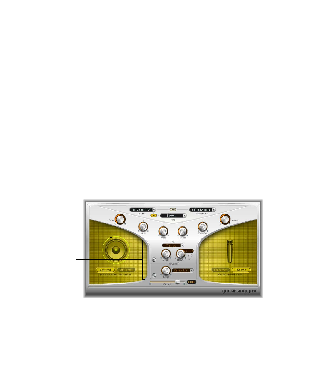
The Guitar Amp Pro window is organized into four main sections.
Amp section
Effects section
Microphone Position section
 The Amp section has parameters for choosing the Amp, Speaker, and EQ model, and
 The Effects (FX) section is where you control the built-in guitar effects. Below the FX
Microphone Type section
a set of tone, gain, and level controls.
section is the final output control.
Chapter 1 Amp Modeling 15
Page 16

 The Microphone Position section is where you set the position of the microphone on
the speaker.
 The Microphone Type section is where you choose which type of microphone
captures the amp’s sound.
Amp Section
 Amp pop-up menu: Choose the amp model you want to use. The choices are:
Model Description
UK Combo 30W Neutral sounding amp, well suited for clean or crunchy rhythm parts.
UK Top 50W Quite aggressive in the high frequency range, well suited for classical rock
sounds.
US Combo 40W Clean sounding Amp model, well suited for funk and jazz sounds.
US Hot Combo 40W Emphasizes the high mids of the frequency range, making this model ideal
for solo sounds.
US Hot Top 100W This Amp produces very fat sounds, even at low Master settings, than result
in broad sounds with a lot of “oomph.”
Custom 50W With the Presence parameter set to 0, this Amp model is well suited for
smooth fusion lead sounds.
British Clean Simulates the classic British Class A combos used continuously since the
1960s for rock music, without any significant modification. This model is
ideally suited for clean or crunchy rhythm parts.
British Gain Emulates the sound of a British tube head, and is synonymous with rocking,
powerful rhythm parts and lead guitars with a rich sustain.
American Clean Emulates the traditional full tube combos used for clean and crunchy
sounds.
American Gain Emulates a modern Hi-Gain head, making it suitable for distorted rhythm
and lead parts.
Clean Tube Amp Emulates a tube amp model with very low gain (distortion only when using
very high input levels or Gain/Master settings).
16 Chapter 1 Amp Modeling
Page 17

 Speaker pop-up menu: Choose one of the 15 speaker models. The choices are:
Speaker type Description
UK 1x12 open back Classic open enclosure with one 12" speaker, neutral, well-balanced,
multifunctional.
UK 2x12 open back Classic open enclosure with two 12" speaker, neutral, well-balanced,
multifunctional.
UK 2x12 closed Loads of resonance in the low frequency range, therefore well suited for
Combos: crunchy sounds are also possible with low Bass control settings.
UK 4x12 closed slanted when used in combination with off-center miking, you will get an
interesting mid frequency range; therefore this model works well when
combined with High Gain amps.
US 1x10 open back Not much resonance in the low frequency range. Suitable for use with
(blues) harmonicas.
US 1x12 open back 1 Open enclosure of an American lead combo with a single 12" speaker.
US 1x12 open back 2 Open enclosure of an American clean/crunch combo with a single
12" speaker.
US 1x12 open back 3 Open enclosure of another American clean/crunch combo with a single
12" speaker.
US broad range Cabinet simulation of a classic electric piano speaker.
Analog simulation Internal speaker simulation of a well-known British 19" tube preamplifier.
UK 1x12 A British Class A tube open back with a single 12" speaker.
UK 4x12 Classic closed enclosure with four 12" speakers (black series), suitable for
Rock.
US 1x12 open back Open enclosure of an American lead combo with a single 12" speaker.
US 1x12 bass reflex Closed bass reflex cabinet with a single 12" speaker.
DI Box This option allows you to bypass the speaker simulation section.
 EQ pop-up menu: Choose one of the four EQ models. The choices are:
British 1, British 2, American, and Modern EQ.
 Amp–Speaker Link button: Links the Amp and Speaker menus so that when you
change the amp model, the speaker associated with that amp is loaded
automatically.
 Amp–EQ Link button: Links the Amp and EQ menus so that when you change the
amp model, the EQ model associated with that amp is loaded automatically.
Each amp model has a speaker and EQ model associated with it. Together, the amp,
speaker, and EQ combined recreate a well-known guitar sound. However, you can
freely combine any speaker or EQ model with any amp by turning off the two Link
buttons.
Chapter 1 Amp Modeling 17
Page 18

 Gain knob: Sets the amount of pre-amplification applied to the input signal. This
control has different effects, dependent on which Amp model is selected. For
example, when using the British Clean amp model, the maximum Gain setting
produces a powerful crunch sound. When using the British Gain or Modern Gain
amps, the same Gain setting produces heavy distortion, suitable for lead solos.
 Bass, Mids, and Treble knobs: Adjusts the frequency ranges of the EQ models, similar
to the tone knobs on a hardware guitar amplifier.
 Presence knob: Adjusts the high frequency range. The Presence parameter affects
only the output (Master) stage of Guitar Amp Pro.
 Master knob: Sets the output volume of the amplifier (going to the speaker).
Typically, for tube amplifiers, increasing the Master level produces a more
compressed and saturated sound, resulting in a more distorted and powerful (louder)
signal. High settings can produce an extremely loud output. In Guitar Amp Pro, the
Master parameter modifies the sonic character, and the final output level is set using
the Output parameter below the FX section. (see below for information).
Effects Section
The Effects section contains Reverb, Tremolo, and Vibrato effects. You can choose either
Tremolo (which modulates the amplitude or volume of the sound) or Vibrato (which
modulates the pitch), and use Reverb together with either one, or separately.
Before you can use or adjust an effect, you must first turn it on by clicking its On button
(with a power on icon). The On button lights when the effect is turned on. The FX and
Reverb On buttons are located to the left of the controls for each effect.
Note: The Effects section is placed before the Master control in the signal flow, and
therefore receives the pre-amplified (pre-Master) signal.
FX Parameters
 FX pop-up menu: Choose either Tremolo or Vibrato from the menu.
 Depth knob: Sets the intensity of the modulation.
 Speed knob: Sets the speed of the modulation (in Hz). Lower settings produce a
smooth and floating sound, while higher settings produce a rotor-like effect.
 Sync button: When turned on, the Speed is synchronized to the project tempo. When
Sync is activate, adjusting the Speed parameter lets you select different musical note
values. Set the Speed parameter to the desired value, and whichever effect you have
chosen will be perfectly synchronized to the project tempo.
Reverb Parameters
 Reverb pop-up menu: Choose one of the three types of spring reverb.
 Level knob: Sets the amount of reverb applied to the pre-amplified amp signal.
18 Chapter 1 Amp Modeling
Page 19

Microphone Position and Microphone Type Sections
After choosing a speaker from the Speaker menu, you can set the type of microphone
emulated, and where the microphone is placed in relation to the speaker.
Microphone Position Parameters
 Centered button: When selected, places the microphone in the center of the speaker
cone, also called on-axis. This placement produces a fuller, more powerful sound,
suitable for blues or jazz guitar tones.
 Off-Center button: When selected, places the microphone on the edge of the speaker,
also referred to as off-axis. This placement produces signal a tone that is brighter and
sharper, but also thinner, suitable for cutting rock or rhythm and blues guitar tones.
When you select either button, the graphic speaker display reflects the current setting.
Microphone Type Parameters
 Condenser button: When selected, emulates the sound of a studio condenser
microphone. The sound of condenser microphones is fine, transparent, and well
balanced.
 Dynamic button: When selected, emulates the sound of a dynamic cardioid
microphone. This microphone type sounds brighter and more cutting, compared to
the Condenser model. At the same time, the lower Mids are less pronounced, making
this model more suitable for miking rock guitar tones.
Note: In practice, combining both microphone types can sound very interesting.
Duplicate the guitar track, and insert Guitar Amp Pro as an insert effect on both
tracks. Select different microphones in both Guitar Amp Pro instances, while
retaining identical settings for all other parameters, and mix the track signal levels.
You can, of course, choose to vary any other parameters, as desired.
Output
Below the Effects section is the Output slider, which serves as the final level control for
Guitar Amp Pro output. The Output parameter can be thought of as a “behind the
cabinet” volume control, and is used to set the level that is fed into the following plugin slots on the channel or into the channel output.
Note: This parameter is distinct from the Master control, which serves a dual purpose—
for sound design, as well as controlling the level of the Amp section.
Chapter 1 Amp Modeling 19
Page 20

Page 21

2 Delay
2
Delay effects store the input signal—and hold it for a short
time—before sending it to the effect input or output.
Most delays allow you to feed a percentage of the delayed signal back to the input,
creating a repeating echo effect. Each subsequent repeat is a little quieter than the
previous one.
The delay time can often be synchronized to the project tempo by matching the grid
resolution of the project, usually in note values or milliseconds.
You can use delays for:
 Doubling individual sounds, making it sound like a group of instruments playing the
same melody.
 Creating echo effects, placing the sound in a large “space.”
 Enhancing the stereo position of tracks in a mix.
Delay effects are generally used as channel insert or bussed effects. They are rarely
used on an overall mix (in an output channel), unless you’re trying to achieve a special
effect, such as an “other worldly” mix.
This chapter describes the delay effects included with Logic Express:
 Echo (see below).
 Sample Delay (see “Sample Delay” on page 22).
 Stereo Delay (see “Stereo Delay” on page 23).
 Tape Delay (see “Tape Delay” on page 24).
21
Page 22

Echo
This simple echo effect always synchronizes the delay time to the project tempo,
allowing you to quickly create echo effects that run in time with your composition.
Echo Parameters
 Time: Sets the grid resolution of the delay time in musical note durations—based on
the project tempo. “T” values represent triplets, “.” values represent dotted notes.
 Repeat: Determines how often the delay effect is repeated.
 Color: Sets the harmonic content (color) of the delay signal.
 Wet and Dry: These individually control the amount of original and effect signal.
Sample Delay
The Sample Delay is not so much an effect as a tool: You can use it to delay a channel
by single sample values. When used in conjunction with the phase inversion
capabilities of the Gain effect, the Sample Delay is well-suited to the correction of
timing problems that may occur with multi-channel microphones. It can also be used
creatively, to emulate stereo microphone channel separation.
The stereo version of the plug-in provides separate controls for each channel, and also
offers a Link L & R option that moves both channels by the same number of samples.
Every sample (at a frequency of 44.1 kHz) is equivalent to the time taken for a sound
wave to travel 7.76 millimeters. Looked at differently: If you delay one channel of a
stereo microphone by 13 samples, this will emulate an acoustic (microphone)
separation of 10 centimeters.
22 Chapter 2 Delay
Page 23
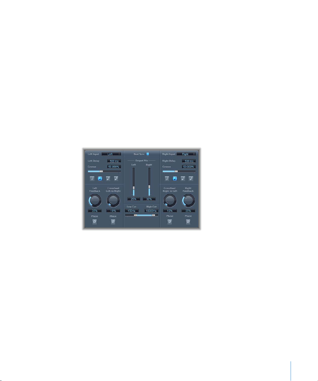
Stereo Delay
The Stereo Delay works much like the Tape Delay (see below), but allows you to set the
Delay, Feedback, and Mix parameters separately for the left and right channel.
The effect also features a Crossfeed knob for each stereo side. It determines the
feedback intensity—or the level at which each signal is routed to the opposite stereo
side.
You can freely use the Stereo Delay on mono tracks or busses, when you want to create
independent delays for the two stereo sides.
Note: If you do use the effect on mono channel strips, the track or bus will have two
channels from the point of insertion (all Insert slots after the chosen slot will be stereo).
This section only covers the additional features offered by the Stereo Delay. For more
information about the parameters shared with the Tape Delay, see the Tape Delay
section below.
 Left Input and Right Input: Use these to choose the input signal for the two stereo
sides. Options include Off, Left, Right, L+R, L-R.
 Feedback Phase button: Use to invert the phase of the corresponding channel’s
feedback signal.
 Crossfeed Left to Right and Crossfeed Right to Left: Use to transfer the feedback signal
of the left channel to the right channel, and vice versa.
 Crossfeed Phase buttons: Use to invert the phase of the crossfed feedback signals.
Chapter 2 Delay 23
Page 24
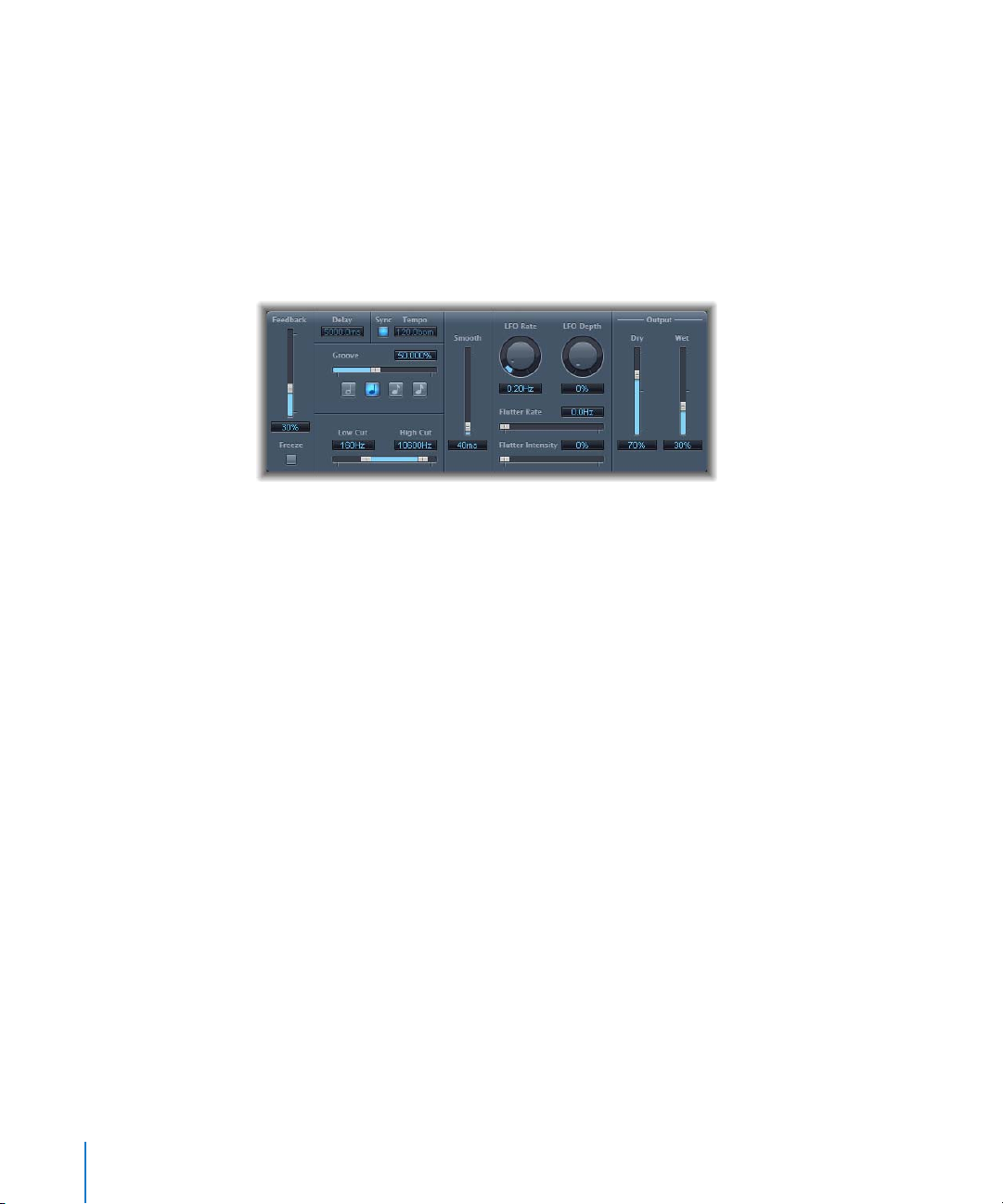
Tape Delay
The Tape Delay simulates the warm sound of vintage tape echo machines, with the
convenience of easy delay time synchronization to your project tempo.
The Tape Delay is equipped with a highpass and lowpass filter in the feedback loop,
making it easy to create authentic dub echo effects, and also includes an LFO for delay
time modulation. The LFO produces a triangular wave, with adjustable speed and
modulation intensity. You can use it to produce pleasant or unusual chorus effects,
even on long delays.
 Feedback: Determines the amount of delayed and filtered signal that is routed back
to the input of the Tape Delay.
 Freeze: Captures the current delay repeats and sustains them until the Freeze
parameter is released.
 Delay: Sets the current delay time in milliseconds (this parameter is dimmed when
you synchronize the delay time to the project tempo).
 Tempo: Sets the current delay time in beats per minute (this parameter is dimmed
when you synchronize the delay time to the project tempo).
 Sync button: Switch this on to synchronize delay repeats to the project tempo
(including tempo changes).
 Note buttons: Click to set the grid resolution for the delay time, in note durations.
 Groove slider: Determines the proximity of every second delay repeat to the absolute
grid position (how close every second delay repeat is, in other words).
 Distortion Level (extended parameter): Determines the level of the distorted (tape
saturation) signal.
 Low Cut and High Cut: Frequencies below the Low Cut value, and above the High Cut
value are filtered out of the source signal.
 LFO Speed: Sets the frequency (speed) of the LFO.
 LFO Depth: Sets the amount of LFO modulation. A value of 0 turns delay modulation
off.
 Flutter parameters: Simulates the speed irregularities of the tape transports used in
analog tape delay units. Flutter Rate adjusts the speed, and Flutter Intensity
determines how pronounced the effect is.
24 Chapter 2 Delay
Page 25

 Smooth: Evens out the LFO and flutter effect.
 Dry and Wet: These individually control the amount of original and effect signal.
Setting the Feedback
When you set the Feedback slider to the lowest possible value, the Tape Delay
generates a single echo. If Feedback is turned all the way up, the echoes are repeated
ad infinitum.
Note: The levels of the original signal and its taps (echo repeats) tend to accumulate,
and may cause distortion. This is where the internal tape saturation circuit comes to the
rescue—it can be used to ensure that these overdriven signals continue to sound
good.
Setting the Groove Value
The Groove value determines the proximity (how close) of every second delay repeat to
the absolute grid position. A Groove setting of 50% means that every delay will have
the same delay time. Settings below 50% result in every second delay being played
earlier in time. Settings above 50% result in every second delay being played later in
time. When you want to create dotted note values, move the Groove slider all the way
to the right (to 75%); for triplets, select the 33.33% setting.
Filtering the Delay Effect
You can shape the sound of the echoes, using the on-board highpass and lowpass
filters. The filters are located in the feedback circuit, meaning that the filtering effect
increases in intensity with each delay repeat. If you’re after an increasingly “muddy”
tone, move the High Cut filter slider towards the left. For ever “thinner” echoes, move
the Low Cut filter slider towards the right.
Note: If you’re unable to hear the effect, even though you seem to have a suitable
configuration, be sure to check out both the Dry/Wet controls and the filter
settings: Move the High Cut filter slider to the far right, and the Low Cut filter slider to
the far left.
Chapter 2 Delay 25
Page 26

Page 27

3 Distortion
3
You can use Distortion effects to recreate the sound of analog
or digital distortion, and to radically transform your audio.
Distortion effects simulate the distortion created by vacuum tubes, transistors, or
digital circuits. Vacuum tubes were used in audio amplifiers before the development of
digital audio technology, and are still used in musical instrument amps today. When
overdriven, they produce a type of distortion which many people find musically
pleasing, and which has become a familiar part of the sound of rock and pop music.
Analog tube distortion adds a distinctive warmth and bite to the signal.
There are also distortion effects which intentionally cause clipping and digital
distortion of the signal. These can be used to modify vocal, music, and other tracks to
produce an intense, unnatural effect, or for creating sound effects.
Distortion effects include parameters for tone, which let you shape the way the
distortion alters the signal (often as a frequency-based filter), and for gain, which let
you control how much the distortion alters the output level of the signal.
Warning: When set to high output levels, distortion effects can damage your hearing
(and speakers). When adjusting effect settings, it is recommended that you lower the
output level of the track, and raise the level gradually when you are finished.
The following sections describe the individual effects included with Logic Express.
 “Bitcrusher” on page 28
 “Clip Distortion” on page 29
 “Distortion” on page 30
 “Distortion II” on page 31
 “Overdrive” on page 32
 “Phase Distortion” on page 33
27
Page 28
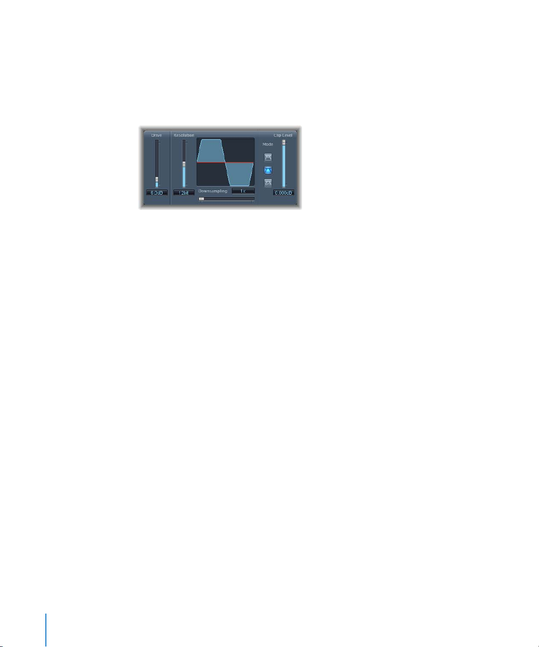
Bitcrusher
The Bitcrusher is a low resolution digital distortion effect. You can use it to emulate the
sound of early digital audio, create artificial aliasing by dividing the sample rate, or
distort signals until they are unrecognizable.
Bitcrusher Parameters
 Drive slider and field: Sets the amount of gain (in decibels) applied to the input signal.
 Resolution slider and field: Sets the bit rate (between 1 and 24 bits).
 Downsampling slider and field: Sets the amount by which the sample rate is reduced.
A value of 1x leaves the signal unchanged, a value of 2x halves the sample rate, and a
value of 10x reduces the sample rate to one-tenth of the original signal. (For example,
if you set Downsampling to 10x, a 44.1 kHz signal is sampled at just 4.41 kHz.)
 Mode buttons: Click one of the buttons to set the distortion mode to Folded, Cut, or
Displaced (each of which is described in the following section).
 Clip Level slider and field: Sets the point below the normal threshold at which the
signal starts clipping.
 Mix slider and field (extended parameter): Determines the balance of dry and wet
signals.
Using the Bitcrusher
Setting the Resolution parameter to a value lower than the bit rate of the original
signal degrades the signal, introducing digital distortion. Lowering the value increases
the number of sampling errors, generating more distortion. At extremely low bit rates,
the amount of distortion can be greater than the level of the usable signal.
The Mode buttons determine whether signal peaks that exceed the clip level are
Folded, Cut, or Displaced (as displayed on the button icons and the resulting waveform
in the display). The kind of clipping that occurs in digital systems is usually closest to
that of the center mode (Cut). Internal distortion may generate clipping similar to the
types generated by the other two modes.
Raising the Drive level tends to increase the amount of clipping at the output of the
Bitcrusher as well.
28 Chapter 3 Distortion
Page 29
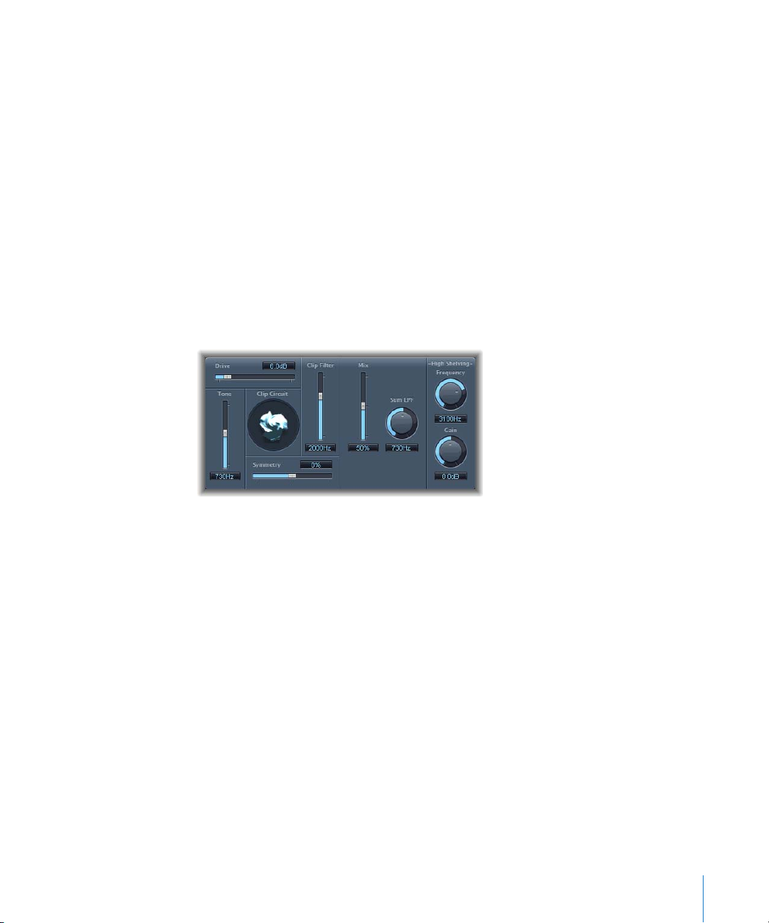
Clip Distortion
Clip Distortion is a nonlinear distortion effect that produces unpredictable spectra. You
can use it to simulate warm, overdriven tube sounds, and also to create drastic distortion.
Clip Distortion features an unusual combination of serially connected filters. After being
amplified by the Drive value, the signal passes through a highpass filter, and is then
subjected to nonlinear distortion, as controlled by the Symmetry parameter. After the
distortion, the signal passes through a lowpass filter. The effected signal is mixed with
the original signal, after which the mixed signal is sent through another lowpass filter.
All three filters have a slope of 6 dB/octave.
This unique combination of filters allows for gaps in the frequency spectra that can
sound quite good with this sort of nonlinear distortion. The clip circuit graphic visually
depicts every parameter except for the High Shelving filter parameters.
Clip Distortion Parameters
 Drive slider and field: Sets the amount of gain applied to the input signal. After being
amplified by the Drive value, the signal passes through a highpass filter.
 Tone slider and field: Sets the cutoff frequency (in Hertz) of the highpass filter.
 Symmetry slider and field: Sets the amount of nonlinear (asymmetrical) distortion
applied to the signal.
 Clip Filter slider and field: Sets the cutoff frequency (in Hertz) of the first lowpass filter
through which the signal passes after distortion.
 Mix slider: Sets the ratio of the effected (wet) signal to the non-effected (dry) signal
following the Clip Filter.
 Sum LPF circular slider and field: Sets the cutoff frequency (in Hertz) of the lowpass
filter through which the mixed signal passes.
 High Shelving Frequency knob and field: Sets the frequency (in Hertz) of the high
shelving filter.
 High Shelving Gain knob and field: Sets the amount of gain applied to the output
signal.
Chapter 3 Distortion 29
Page 30
 Input Gain field and slider (extended parameter): Sets the amount of gain applied to
the input signal.
 Output Gain field and slider (extended parameter): Sets the amount of gain applied to
the output signal.
Using Clip Distortion
If you set the High Shelving Frequency to around 12 kHz, you can use it like the treble
control on a mixer channel strip or a stereo hi-fi amplifier. Unlike those types of treble
controls, however, you can boost or cut the signal by up to ±30 dB using the Gain
parameter.
Distortion
This Distortion effect simulates the lo-fi, dirty distortion generated by a bipolar
transistor. You can use it to simulate playing a musical instrument through a highly
overdriven amplifier, or to create unique distorted sounds.
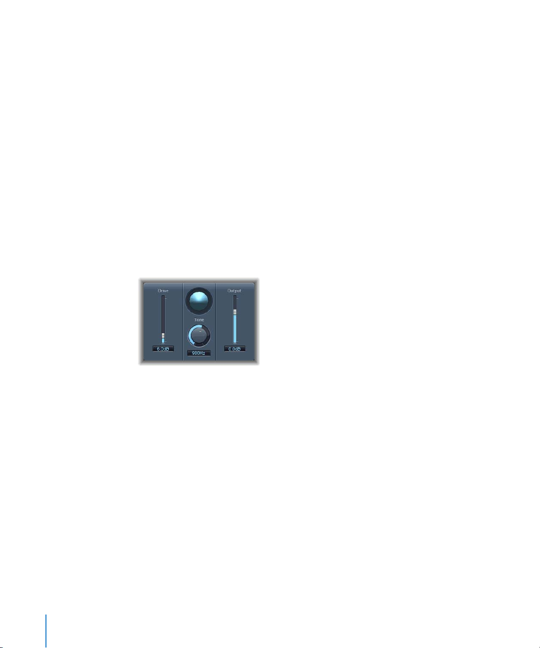
Distortion Parameters
 Drive slider and field: Sets the amount of saturation applied to the signal.
 Tone slider and field: Sets the frequency at which the signal is filtered by a high cut
filter. Filtering the harmonically-rich distorted signal produces a somewhat less
grating, softer tone.
 Output slider and field: Sets the output volume level. This allows you to compensate
for increases in loudness caused by adding distortion.
30 Chapter 3 Distortion
Page 31
Distortion II
Distortion II emulates the distortion effect section of a Hammond B3 organ. You can
use it on musical instruments to recreate this classic effect, or use it creatively when
designing new sounds.
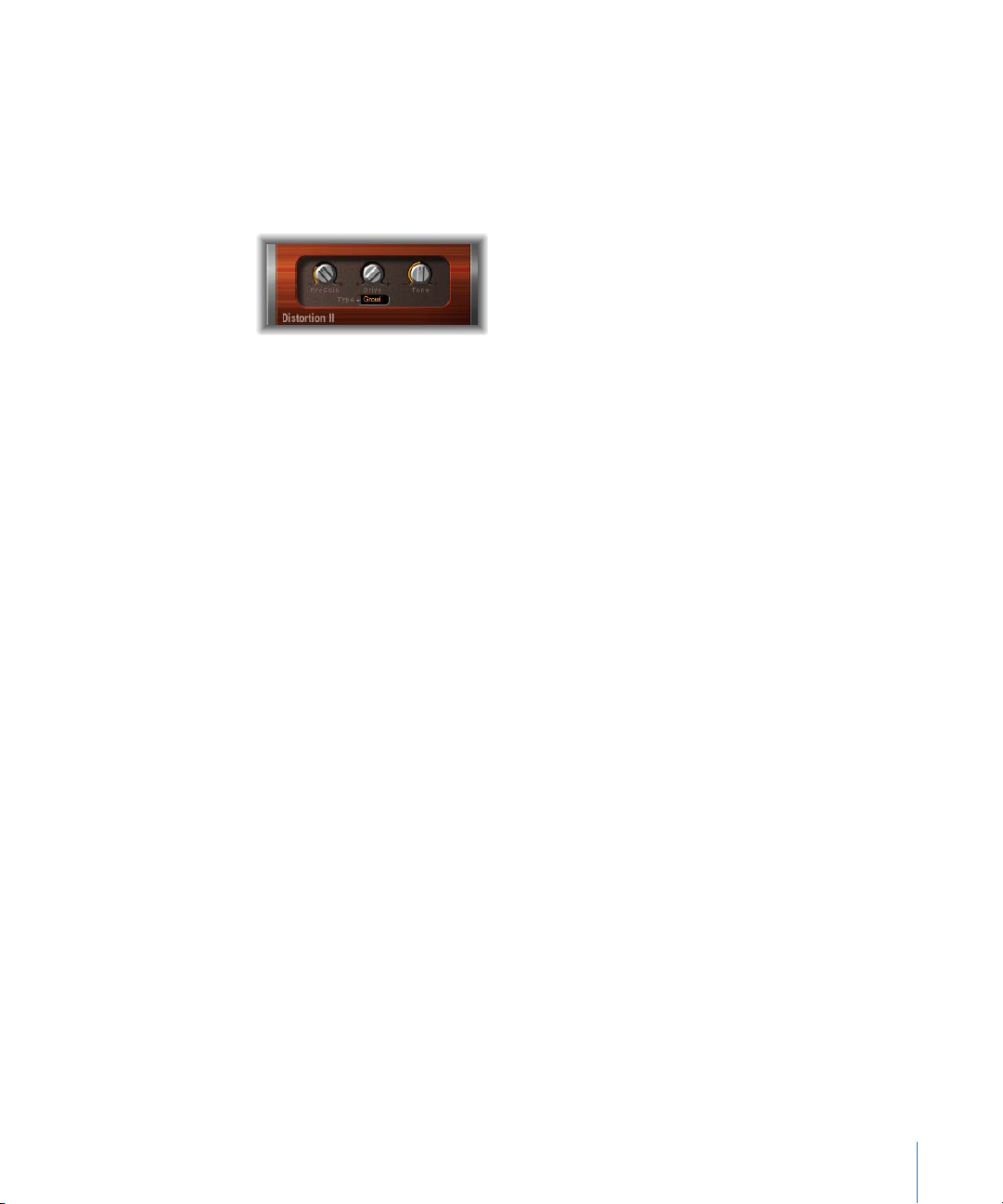
Distortion II Parameters
.
 PreGain dial: Sets the amount of gain applied to the input signal.
 Drive dial: Sets the amount of saturation applied to the signal.
 Tone dial: Sets the frequency at which the signal is filtered. Filtering the
harmonically-rich distorted signal produces a somewhat less grating, softer tone.
 Type pop-up menu: Choose the type of distortion you want to apply. The choices are:
Growl, Bity, and Nasty.
 Growl: Emulates a two-stage tube amplifier, similar to the type found in a Leslie
122 model, often used together with a Hammond B3 organ.
 Bity: Emulates the sound of a bluesy (overdriven) guitar amp.
 Nasty: Produces hard distortion, suitable for creating very aggressive sounds.
Chapter 3 Distortion 31
Page 32

Overdrive
The Overdrive effect emulates the distortion produced by a field effect transistor (FET),
which is commonly used in solid-state musical instrument amplifiers and hardware
effects devices. When saturated, FETs generate a warmer sounding distortion than
bipolar transistors.
Overdrive Parameters
 Drive slider and field: Sets the amount of saturation of the transistor.
 Tone slider and field: Sets the cutoff frequency at which the signal is filtered. Filtering
the harmonically-rich distorted signal produces a somewhat less grating, softer tone.
 Output slider and field: Sets the output volume level. Using the Overdrive plug-in
tends to increase the level of the original signal, and you can compensate for this by
lowering the Output level.
32 Chapter 3 Distortion
Page 33

Phase Distortion
The Phase Distortion effect is based on a modulated delay line, similar to a chorus or
flanger effect (for more information about these effects, see Chapter 9, “Modulation,”
on page 99). Unlike these effects, however, in the Phase Distortion effect the delay time
is not modulated by a low frequency oscillator (LFO), but rather by a lowpass-filtered
version of the input signal itself. This means that the signal modulates its own phase
position. The input signal only passes the delay line and is not affected by any other
process.
Phase Distortion Parameters
 Monitor button: Turn on to hear only the input signal, or turn off to hear the mixed
signal.
 Cutoff circular slider and field: Sets the cutoff frequency of the resonant lowpass filter
through which the input signal passes.
 Resonance circular slider and field: Sets the resonance of the resonant lowpass filter
through which the input signal passes.
 Mix slider and field: Adjusts the percentage of the effected signal mixed with the
original signal.
 Max Modulation slider and field: Sets the maximum delay time.
 Intensity slider and field: Sets the amount of modulation applied to the signal.
 Phase Reverse pop-up menu (extended parameter): Choose On to have positive input
values reduce the delay time on the right channel. Only available for stereo instances
of the Phase Distortion effect.
Chapter 3 Distortion 33
Page 34

Using the Phase Distortion
The input signal only passes the delay line and is not affected by any other process. The
Mix parameter blends the effected signal with the original signal. The delay time is
modulated by a side chain signal—namely, the input signal. The input signal passes
through a resonant lowpass filter, with dedicated Cutoff frequency and Resonance
controls. You can listen to the filtered side chain (instead of the Mix signal) by turning
on the Monitor button. You set the maximum delay time via the Max Modulation
parameter. The amount of modulation itself is controlled with Intensity.
Below the other parameters is the Phase Reverse parameter. Normally, a positive input
value results in a longer delay time. By turning on the Phase Reverse parameter,
positive input values result in a reduction of the delay time on the right channel only.
This is only available for stereo instances of the effect.
34 Chapter 3 Distortion
Page 35

4 Dynamics
4
You can use Dynamics effects to control the perceived
loudness of your audio, add focus and punch to tracks and
projects, and optimize the sound for playback in different
situations.
The dynamic range of an audio signal is the range between the softest and loudest
parts of the signal (technically, between the lowest and the highest amplitude). Using
dynamics effects, you can adjust the dynamic range of individual audio files, tracks, or
an overall project to increase the perceived loudness, and highlight the most important
sounds while making sure softer sounds are not lost in the mix. Dynamics effects
include compressors, limiters, and noise gates.
Compressors
A compressor works like an automatic volume control, lowering the volume whenever
it rises above a certain level, called the threshold. Why would you want to reduce the
dynamic level? By cutting the highest parts of the signal (called peaks), the compressor
lets you raise the overall level of the signal, increasing the perceived volume. This gives
the sound more focus by making the louder foreground parts stand out, while
preventing the softer background parts from becoming inaudible. Compression also
tends to make sounds tighter or punchier because transients are emphasized
(depending on attack and release settings) and because the maximum volume is
reached more swiftly.
In addition, compression can help make a project sound better when played back in
different audio environments. For example, the speakers on a television set or in a car
sound system typically have a narrower dynamic range than the sound system in a
theater. Compressing the overall mix can help make the sound fuller and clearer in
lower-fidelity playback situations.
Compressors are typically used on vocal tracks to make the vocals prominent in an
overall mix. They can also be used on music and sound effects tracks, but rarely on
ambience tracks.
35
Page 36

Some compressors, called multiband compressors, can divide the incoming signal into
different frequency bands, and apply different compression settings to each band. This
helps achieve the maximum level without introducing compression artifacts, and is
typically used on an overall project mix.
Expanders
Expanders are similar to compressors, except that they raise, rather than lower, the
signal when it exceeds the threshold. Expanders are used to enliven the audio signal.
Limiters
Limiters (also called peak limiters) work in a similar way to compressors, in that they
reduce the audio signal when it exceeds a set threshold. The difference is that while a
compressor gradually lowers the signal level above the threshold, a limiter quickly
reduces any signal louder than the threshold to the threshold level. The main use of a
limiter is to prevent clipping, while preserving the maximum overall signal level.
Noise Gates
Noise gates alter the signal in the opposite way that compressors or limiters do. While a
compressor lowers the level when the signal goes above the threshold, a noise gate
lowers the signal whenever it is below the threshold. Louder sounds pass through
unchanged, but softer sounds, such as ambient noise or the decay of a sustained
instrument, are cut off. Noise gates can be used to eliminate low-level noise or hum
from an audio signal.
The following sections describe the effects included with Logic Express.
 “Compressor” on page 37
 “DeEsser” on page 41
 “Ducker” on page 43
 “Enveloper” on page 45
 “Expander” on page 47
 “Limiter” on page 48
 “Noise Gate” on page 49
 “Preset Multipressor” on page 52
 “Silver Compressor” on page 53
 “Silver Gate” on page 54
36 Chapter 4 Dynamics
Page 37

Compressor
The Compressor is designed to emulate the sound and response of a professional-level
analog (hardware) compressor. It tightens up your audio by reducing sounds that
exceed a certain threshold level, smoothing out the dynamics and increasing the
overall volume—the perceived loudness. Compression helps bring the key parts of a
track or a mix into focus while preventing softer parts from being inaudible. It is
probably the most versatile and widely used sound-shaping tool used in mixing, next
to EQ.
You can use the Compressor with individual tracks, including vocal, instrumental, and
effects tracks, as well as on the overall mix. In most cases, you’ll want to insert the
Compressor directly into a channel.
Compressor Parameters
 Circuit Type slider and field: Choose the type of circuit emulated by the Compressor.
The choices are Platinum, Classic A_R, Classic A_U, VCA, FET, and Opto (optical).
 Gain Reduction display: Shows the amount of compression applied as the audio
plays.
 Attack knob and field: Sets the attack time (the amount of time it takes for the
compressor to react when the signal exceeds the threshold).
 Release knob and field: Sets the release time (the amount of time it takes for the
compressor to stop reducing the signal once the signal falls below the threshold).
 Auto button: When selected, the release time dynamically adjusts to the audio
material.
 Compression curve display: Shows the compression curve created by the Ratio and
Knee parameters, with input as the X-axis and output as the Y-axis.
 Ratio slider and field: Sets the compression ratio (the ratio by which the signal is
reduced when it exceeds the threshold).
 Knee slider and field: Adjusts whether the signal is compressed immediately or more
gradually at levels close to the threshold.
Chapter 4 Dynamics 37
Page 38

 Compression Threshold slider and field: Sets the threshold for the Compressor (the
level above which the signal is reduced).
 Peak/RMS buttons: Turn on one or the other to set whether the Compressor analyzes
the signal using Peak or RMS method when using the Platinum Circuit Type.
 Gain slider and field: Sets the amount of gain applied to the output signal.
 Gain pop-up menu: Choose a value to raise the output level in order to compensate
for volume reduction caused by compression. The choices are OFF, 0 dB, and –12 dB.
 Limiter Threshold slider and field: Sets the threshold level for the limiter.
 Limiter button: Turns the integrated limiter on or off.
Extended Parameters
 Output Distortion pop-up menu: Choose whether to apply clipping above 0 dB, and
what type of clipping is applied. The values are off, soft, hard, and clip.
 Mix slider and field: Determines the balance of dry and wet signals.
Side Chain Filter
 Activity pop-up menu: Choose whether the Compressor side chain is turned on or off,
or in listen (audition) mode. The choices are off, listen, and on.
 Mode pop-up menu: Choose the type of filter used for the side chain. The choices are
BP (bandpass), LP (lowpass), HP (highpass), ParEQ (parametric), and HS (high
shelving).
 Frequency slider and field: Sets the frequency for the side chain filter.
 Q slider and field: Sets the bandwidth of the frequency band affected by the side
chain filter.
 Gain slider and field: Sets the amount of gain applied to the side chain signal.
38 Chapter 4 Dynamics
Page 39

Using the Compressor
The following sections provide information on using each of the main Compressor
parameters.
Threshold and Ratio
The most important Compressor parameters are Threshold and Ratio. The Threshold is
the level (in decibels) above which the signal is reduced by the amount set as the Ratio.
Because the Ratio is a percentage of the overall level, the more the signal exceeds the
threshold, the more it is reduced. For example, with the Threshold set at –6 dB and the
Ratio set to 4:1, a –2 dB peak in the signal (4 dB louder than the threshold) is reduced
by 3 dB so that it is just 1 dB above the threshold, while a +6 dB peak (12 dB above the
threshold) is reduced by 9 dB so that it is 3 dB above the threshold. The scale of
dynamics is preserved, but the differences between the peaks are evened out.
Attack and Release
After Threshold and Ratio, the most important parameters are Attack and Release. You
use the Attack and Release parameters to shape the dynamic response of the
Compressor. The Attack parameter sets the amount of time after the audio exceeds the
threshold before the Compressor starts reducing the signal. For many sounds, including
voices and musical instruments, the initial attack is important for defining the sound,
and setting the Attack higher ensures that the original attack is not altered. To
maximize the level of an overall mix, setting the Attack lower ensures that the
Compressor starts reducing the signal right away.
Similarly, the Release parameters controls how quickly the Compressor stops reducing
the signal once it falls below the threshold. Setting the Release higher makes the
difference in dynamics smoother, while setting it lower can make the difference more
abrupt. Adjusting the Attack and Release parameters properly can help avoid pumping,
a common side effect of compression.
Knee
The Knee parameter smooths the effect of the Compressor by controlling whether the
signal is slightly compressed as it approaches the threshold. Setting the Knee close to 0
(zero) means that levels just below the threshold are not compressed at all (1:1 ratio),
while levels at the threshold are compressed by the full Ratio amount (4:1, 10:1, or
more). This is what audio engineers call hard knee compression, which can cause the
transition to be abrupt as the signal reaches the threshold. Increasing the value of the
Knee parameter applies some compression to the signal as it approaches the threshold,
creating a smoother transition. This is called soft knee compression. Setting the Knee
parameter controls the shape of compression around the threshold, while the
Threshold and Ratio parameters control its intensity.
Chapter 4 Dynamics 39
Page 40

Other Parameters
Because the Compressor works by reducing levels, the overall volume of its output is
typically lower than the input signal. You can adjust the output level using the Gain
slider.
You can use the Auto Gain parameter to compensate for the reduction in gain
produced by compression, referenced to either –12 dB or 0 dB. Auto Gain sets the level
of gain (amplification) to a value of T—(T/R), where T = the Threshold and R = the
Ratio.
The Gain Reduction Meter displays the amount of compression occurring as the signal
plays. It’s useful to watch how much your tracks are being compressed, and to make
sure they’re not being overly compressed.
When using the Platinum Circuit Type, the Compressor can analyze the signal using
one of two methods: Peak or RMS (root mean square). While Peak is more technically
accurate, RMS provides a better indication of how people perceive the signal’s
loudness. When using the Compressor primarily as a limiter, select the Peak button.
When compressing individual tracks, especially music tracks, select the RMS button.
If you activate Auto Gain and RMS simultaneously, the signal may be saturated. If you
hear any distortion, switch Auto Gain off and adjust the Gain slider until the distortion
is gone.
40 Chapter 4 Dynamics
Page 41

DeEsser
The DeEsser is a frequency-specific compressor, designed to compress only a particular
frequency band within a complex audio signal. It is used to eliminate hiss (also called
sibilance) from the signal. The advantage of using the DeEsser instead of an EQ effect
to cut high frequencies is that it compresses the signal dynamically rather than
statically. This prevents the sound from becoming darker when no sibilance is present
in the signal. The DeEsser features extremely fast attack and release times.
When using the DeEsser, you can set the frequency range being compressed (the
Suppressor frequency) independently of the frequency range being analyzed (the
Detector frequency). The two ranges appear separately in the DeEsser window for easy
comparison. The DeEsser performs gain reduction on the Suppressor frequency range
for as long as the threshold for the Detector frequency is exceeded.
The DeEsser does not use a frequency dividing network (a crossover utilizing low and
highpass filters). Rather, it is based on subtracting the isolated frequency band, and so
does not alter the phase curve.
DeEsser Parameters
The Detector parameters are on the left side of the DeEsser window, and the
Suppressor parameters are on the right. The center section includes the Detector and
Suppressor displays and the Smoothing slider.
Detector Section
 Detector Frequency knob: Sets the frequency range the DeEsser analyzes.
 Detector Sensitivity knob: Sets the degree of responsiveness to the input signal. At
higher ratios, the Detector reacts more responsively.
 Monitor pop-up menu: Choose whether to monitor the filtered Detector signal (Det.),
the filtered Suppressor signal (Sup.), or the sound removed from the input signal in
response to the Sensitivity parameter (Sens.). Choose Off to hear the DeEsser output.
Chapter 4 Dynamics 41
Page 42

Suppressor Section
 Suppressor Frequency knob: Sets the frequency band that is reduced when the
Detector frequency sensitivity threshold is exceeded.
 Strength knob: Sets the amount of gain reduction around the Suppressor frequency.
Center Section
 Detector and Suppressor frequency displays: The upper display shows the Detector
frequency range, and the lower display shows the Suppressor frequency range (in
Hz).
 Smoothing slider: Sets the reaction speed of the gain reduction start and end phases.
Smoothing controls both the attack and release time (as they are used by
compressors).
42 Chapter 4 Dynamics
Page 43

Ducker
Ducking is a common technique used in radio and television broadcasting: when the
DJ/announcer speaks while music is playing, the music level is automatically reduced.
When the announcement has finished, the music is automatically raised to its original
volume level.
The Ducker plug-in provides a simple means of performing this process. It can even
reduce the music level before the speaker starts (but this introduces a small amount of
latency).
Ducker Parameters
 Intensity: Defines the amount of volume reduction (of the music mix track—this, in
effect, is the output signal).
 Threshold: Determines the lowest level that a side chain signal must attain before it
begins to reduce the (music mix) output level by the amount set with the Intensity
slider. If the side chain signal level doesn’t reach the threshold, the (music mix) track
volume is not affected.
 Attack: Controls how quickly the volume is reduced. If you want the (music mix)
signal to be gently faded out, set this slider to a high value. This value also controls
whether or not the volume is reduced before the threshold is reached—the earlier
this occurs, the more latency is introduced. It should be noted that this only works if
the ducking signal is not live (in other words, the ducking signal must be an existing
recording): Logic Express needs to analyze the signal level before it is played back, to
anticipate the point where ducking begins.
 Hold: Determines the duration that the (music mix) track volume is reduced for. This
control avoids a chattering effect that can be caused by a rapidly changing sidechain
level. If the sidechain level hovers around the threshold value, rather than clearly
exceeding or falling short of it, set the Hold parameter to a high value to compensate
for rapid volume reductions.
Chapter 4 Dynamics 43
Page 44

 Release: Controls how quickly the volume returns to the original level. Set to a high
value if you want the music mix to slowly fade up after the announcement.
Using the Ducker
For technical reasons, the Ducker plug-in can only be inserted in output and aux
channels.
To use the Ducker plug-in:
1 Insert the Ducker plug-in into an audio or aux channel strip.
2 Assign all track outputs that are supposed to “duck” (dynamically lower the volume of
the mix) to a bus (using one of the Sends).
3 Select the bus (aux channel strip) that carries the ducking (vocal) signal in the Side
Chain menu of the Ducker plug-in.
Note: Unlike all other side chain capable plug-ins, the Ducker side chain is mixed with
the output signal after passing through the plug-in. This ensures that the ducking side
chain signal (the voice over) is heard at the output.
4 Adjust the Ducker’s parameters.
44 Chapter 4 Dynamics
Page 45

Enveloper
The Enveloper is an unusual effect that lets you shape transients—the attack and
release phases of a signal. This gives it a unique capability to shape the signal, and can
be used to achieve impressive results different than any other dynamics effect.
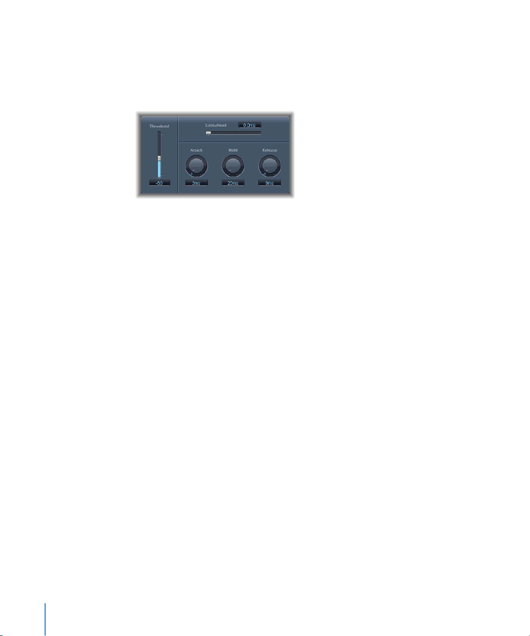
Enveloper Parameters
The Gain and Time controls on the left apply to the attack portion of the signal, while
the Gain and Time controls on the right apply to the release portion.
 Threshold slider and field: Sets the threshold above which the attack and release
levels are altered.
 (Attack) Gain slider and field: Sets the gain on the attack phase of the signal. When
set to the center (0) position, the signal is unaffected.
 (Attack) Time knob: Sets the duration from the beginning of the signal considered as
the attack.
 Display area: Graphically displays the attack and release curves applied to the signal.
 (Release) Time knob: Sets the duration of the signal considered as the release.
 (Release) Gain slider: Sets the gain on the release phase of the signal. When set to the
center (0) position, the signal is unaffected.
 Out Level slider: Sets the level of the output signal.
 Lookahead slider and field: Adjusts how far the Enveloper looks ahead in the signal.
Using the Enveloper
The most important parameters of the Enveloper are the two Gain sliders, one on each
side of the central display area, that govern Attack (left) and Release (right). Raising the
gain emphasizes the attack or release phase, respectively, while lowering the gain
attenuates the corresponding phase.
As an example, boosting the attack gives a drum sound more snap, or amplifies the
initial pluck (or pick) sound of a stringed instrument. Cutting the attack causes
percussive signals to fade in more softly. You can also mute the attack, making it
virtually inaudible. Another handy application for this effect is to mask the poor timing
of accompanying instruments.
Chapter 4 Dynamics 45
Page 46

Emphasizing the release also boosts any reverb applied to the affected track.
Conversely, toning down the release phase makes tracks originally drenched in reverb
sound drier. This is particularly useful when working with drum loops, but it has many
other applications as well. Let your imagination be your guide.
When using the Enveloper, set the Threshold to the minimum value and leave it there.
Only when you seriously raise the release phase, which boosts the noise level of the
original recording, should you raise the Threshold slider a little. This limits the Enveloper
to affecting only the useful part of the signal.
Drastic boosting or cutting of either the release or attack phase may change the overall
level of the signal. You can compensate for this by lowering the Out Level slider.
The Time parameters for attack and release (below the display area) enable you to
access the time-based intervals that the effect interprets as the attack and release
phases. Generally, you’ll find values of around 20 ms (attack) and 1500 ms (release) are
fine to start with. Adjust them accordingly for the type of signal that you’re processing.
The Lookahead slider allows you to define how far ahead in the signal the Enveloper
looks to anticipate future events. Normally, you won’t need to use this feature, except
possibly for signals with extremely sensitive transients. If you do raise the Lookahead
value, you may need to adjust the attack time accordingly.
In contrast to a compressor or expander, the Enveloper operates independently of the
absolute level of the input signal—provided the Threshold slider is set to the lowest
possible value.
46 Chapter 4 Dynamics
Page 47

Expander
The Expander is similar to a compressor except that it increases, rather than reduces,
the dynamic range above the Threshold level. You can use the Expander to add
liveliness and freshness to your audio, specifically by emphasizing the transients of
highly compressed signals.
Expander Parameters
 Threshold slider and field: Sets the level above which the Expander expands the
signal.
 Ratio slider and field: Sets the ratio by which the signal is expanded when it exceeds
the threshold.
 Attack knob and field: Sets the amount of time it takes for the expander to react
when the signal exceeds the threshold.
 Release knob and field: Sets the amount of time it takes for the expander to stop
expanding the signal once the signal falls below the threshold.
 Knee knob and field: Sets whether the signal is slightly expanded at levels just below
the threshold.
 Gain slider and field: Sets the amount of output gain.
 Auto Gain button: When selected, Auto Gain compensates for the increase in gain
produced by expansion.
 Expansion display: Shows the expansion curve applied to the signal.
 Peak/RMS buttons: Turn on one or the other to set whether the Expander uses the
Peak or RMS method to analyze the signal.
Because the Expander is a genuine upward expander (as opposed to a downward
expander that increases the dynamic range below the Threshold), the Ratio slider
features a value range of 1:1 to 0.5:1.
Chapter 4 Dynamics 47
Page 48

When using the Expander with Auto Gain active, the signal will sound softer even
when the peak level remains the same; in other words, the expander decreases
loudness. If you dramatically change the dynamics of a signal (by setting higher
Threshold and Ratio values), you may find that you need to reduce the output level
using the Gain slider to avoid distortion. In most cases, turning on Auto Gain will adjust
the signal to the correct level.
Limiter
The Limiter functions similarly to a compressor with one important difference: where a
compressor proportionally reduces the signal when it exceeds the threshold, a limiter
reduces any peak above the threshold to the threshold level, effectively limiting the
signal to this level. The Limiter is used primarily as a mastering effect.
Limiter Parameters
 Gain reduction meter: Shows the amount of limiting while the signal plays.
 Gain slider and field: Sets the amount of gain applied to the input signal.
 Lookahead slider and field: Adjusts how far ahead (in milliseconds) the Limiter
analyzes the audio signal.
 Release slider and field: Sets the amount of time after the signal falls below the
threshold before the Limiter stops limiting.
 Output Level knob and field: Sets the output level of the signal.
 Softknee button: When selected, the signal is limited only when it reaches the
threshold. When switched on, the transition to full limiting is nonlinear, producing a
softer, less abrupt effect, and reducing distortion artifacts that can be produced by
hard limiting.
48 Chapter 4 Dynamics
Page 49

The Lookahead parameter allows the Limiter to look forward in the audio so that it can
react earlier to peak volumes by adjusting the amount of reduction. Using Lookahead
causes latency, but this latency has no perceptible effect when you use the Limiter as a
mastering effect, on previously recorded material. Set Lookahead to higher values if
you want the limiting effect to take place before the maximum level is reached,
creating a smoother transition.
Typically, you apply the Limiter as the very last effect in the mastering signal chain. In
this case, you use the Limiter to raise the overall volume of the signal, so that it reaches
but does not exceed 0 dB.
The Limiter is designed in such a way that if set to 0 dB Gain and 0 dB Output Level, it
has no effect (on a normalized signal). If the signal clips (red gain line), the Limiter—
using its basic settings—reduces the level before clipping can occur. (However, the
Limiter cannot fix audio that was clipped during recording).
Noise Gate
The Noise Gate is commonly used to suppress unwanted noise that is audible when the
audio signal is at a low level. You can use it to remove background noise, crosstalk from
other signal sources, and low-level hum, among other uses.
The Noise Gate works by allowing signals above the Threshold level to pass unimpeded
while reducing signals below the Threshold level. This allows you to remove lower-level
parts of the signal, while allowing the intended parts of the audio to pass.
Noise Gate Parameters
Main Parameters
 Threshold slider and field:
 Reduction slider and field: Sets the amount by which the signal is reduced.
 Attack knob and field: Sets the amount of time it takes to fully open the gate after
the signal exceeds the threshold.
Sets the level (in decibels) below which the signal is reduced.
Chapter 4 Dynamics 49
Page 50

 Hold knob and field: Sets the amount of time the gate is kept open after the signal
falls below the threshold.
 Release knob and field: Sets the amount of time it takes to fully close the gate after
the signal falls below the threshold.
 Hysteresis slider and field: Sets the difference (in decibels) between the threshold
values that open and close the gate, to prevent it rapidly opening and closing when
the input signal is close to the threshold.
 Lookahead slider and field: Sets how far ahead (in milliseconds) the noise gate
analyzes the signal.
Sidechain Parameters
 Monitor button: Turn on to preview the Sidechain signal, including the effect of the
High and Low Cut filters.
 High Cut slider and field: Sets the upper cutoff frequency for the sidechain signal.
 Low Cut slider and field: Sets the lower cutoff frequency for the sidechain signal.
When no external sidechain is selected, the input signal is used as the sidechain.
Using the Noise Gate
In most situations, setting the Reduction slider to the lowest possible value ensures
that sounds below the Threshold are completely suppressed. Setting it to a higher
value attenuates low-level sounds but still allows them to pass. You can also set
Reduction to a value greater than 0 (zero) to boost the signal by up to 20 dB. This is
useful for ducking effects.
The three rotary knobs for Attack, Hold, and Release modify the dynamic response of
the Noise Gate. If you want the gate to open extremely quickly, say for percussive
signals such as drums, set the Attack knob to a lower value. For other sounds, such as
string pads, where the signal fades in more gradually, set Attack to a higher value for a
smoother effect. Similarly, when you are working with signals that fade out gradually or
which have longer reverb tails, set the Release knob to a higher value so that the signal
fades naturally.
The Hold knob determines the minimum amount of time that the gate stays open. This
avoids abrupt changes (called chattering) caused when the Noise Gate opens and
closes rapidly.
50 Chapter 4 Dynamics
Page 51

The Hysteresis slider provides another option for avoiding chattering, without needing
to define a minimum Hold time. You use it to set the range between the threshold
values that open and close the Noise Gate. This is useful when the signal level jitters
around the Threshold, fluctuating slightly but rapidly around it. This causes the Noise
Gate to switch on and off repeatedly, producing an undesirable chattering effect. Using
the Hysteresis slider, you can set the Noise Gate to open at the Threshold level and
remain open until the level drops below another, lower, level. As long as the difference
between these two values is large enough to contain the fluctuating level of the
incoming signal, the Noise Gate can function without creating chatter. This value is
always negative. Generally, –6 dB is a good place to start.
In some situations, you may find that the levels of the signal you want to keep and the
levels of the noise are close enough to be difficult to separate. For example, if you are
recording a drum kit, and using the Noise Gate to isolate the sound of the snare drum,
the hi-hat may also open the gate in many cases. To remedy this sort of situation, you
can use the Sidechain controls to isolate the desired signal using Hi and Low Cut filters.
To use the Sidechain filters, click the Monitor button to turn on monitoring. This lets
you hear how the Hi and Low Cut filters will affect the incoming signal. Now you can
drag the High Cut slider to set the frequency above which the signal is filtered out, and
drag the Low Cut slider to set the frequency below which the signal is filtered. These
filters only allow very high (loud) signal peaks in their range to pass. In our example,
you could remove the hi-hat’s signal, which is higher in frequency, using the Hi Cut
filter, and allow the snare signal to pass. You can turn monitoring off to set a suitable
Threshold level more easily.
Chapter 4 Dynamics 51
Page 52

Preset Multipressor
The Preset Multipressor is an easy-to-use variant of the Logic Pro Multipressor plug-in.
A multi-band compressor splits the incoming signal into different frequency bands
before applying compression. These frequency bands are then compressed
independently. Following compression, the frequency bands are mixed back together,
and sent out of the plug-in. The aim of independent compression on different
frequency bands is to reach high compression levels on the bands that need it, without
the pumping effect (on other bands) normally heard at high compression levels.
The interface of the Preset Multipressor features a menu that allows you to choose
between settings optimized for various genres; the names of the presets are pretty
much self-explanatory. Make use of the different presets and use your ears to
determine which one best fits your needs.
52 Chapter 4 Dynamics
Page 53

Silver Compressor
The Silver Compressor is a simplified version of the Compressor. It has fewer
parameters and requires less CPU power.
Silver Compressor Parameters
 Gain Reduction display: Shows the amount of compression applied as the audio
plays.
 Threshold slider and field: Sets the threshold for the Compressor (the level above
which the signal is reduced.)
 Attack knob and field: Sets the attack time (the amount of time it takes for the
compressor to react when the signal exceeds the threshold).
 Release knob and field: Sets the release time (the amount of time it takes for the
compressor to stop reducing the signal once the signal falls below the threshold).
 Ratio slider and field: Sets the compression ratio (the ratio by which the signal is
reduced when it exceeds the threshold.)
Using the Silver Compressor
The parameters of the Silver Compressor work in the same way as on the Compressor.
For more information, see “Compressor” on page 37.
Chapter 4 Dynamics 53
Page 54
Silver Gate
The Silver Gate is a simplified version of the Noise Gate. It has fewer parameters and
requires less CPU power.
Silver Gate Parameters
 Lookahead slider and field: Adjusts how far ahead (in milliseconds) the noise gate
analyzes the signal.
 Threshold slider and field: Sets the level (in decibels) below which the signal is
reduced.
 Attack knob and field: Sets the amount of time it takes to fully open the gate after
the signal exceeds the threshold.
 Hold knob and field: Sets the amount of time the gate is kept open after the signal
falls below the threshold.
 Release knob and field: Sets the amount of time it takes to fully close the gate after
the signal falls below the threshold.
Using the Silver Gate
The parameters of the Silver Gate work in the same way as on the Noise Gate. For more
information, see “Noise Gate” on page 49.
54 Chapter 4 Dynamics
Page 55

5 EQ
5
EQ (short for Equalization) lets you shape the sound of your
audio by changing the level of specific frequency bands.
EQ is one of the most commonly used audio effects, both for music projects and in
post-production work for video. You can use EQ to shape the sound of an audio file,
track, or project by adjusting specific frequencies or frequency ranges. Using EQ, you
can create both subtle and extreme changes to the sound of your projects.
EQ effects include a variety of single-band filters and multiband EQs. All EQ effects use
filters which allow certain frequencies to pass through unchanged, while raising or
lowering the level of other frequencies (also referred to as boosting or cutting
frequencies). EQs can be used as “broad brush” effects to boost or cut a large range of
frequencies, and some EQs (particularly parametric and multiband EQs) can be used for
more precise work.
Single Band EQs
The simplest types of EQ effects are single band EQs, which include low and high cut,
low and highpass, shelving, and parametric EQ.
 Low cut EQ only attenuates frequencies below a specific frequency, called the cutoff
frequency, by a fixed number of decibels per octave, called the slope. High cut EQ
only attenuates frequencies above its cutoff frequency, by a fixed slope.
 Lowpass EQ attenuates frequencies above the cutoff frequency, while highpass EQ
lowers frequencies below the cutoff. In addition, you can control the slope of the
filter (how gradually frequencies beyond the cutoff are attenuated) using the Order
parameter.
 High and low shelving EQ lets you set the cutoff frequency and also control the gain
(the amount of boost or cut), allowing you to change it by a fixed amount rather
than a slope.
 Parametric EQ boosts or cuts all frequencies close to the center frequency (both above
and below the center frequency). You can set the center frequency, and also set the
bandwidth or Q, which determines how wide a range of frequencies around the
center frequency are altered.
55
Page 56

Multiband EQs
Multiband EQs give you control over a set of filters which, together, cover a large part
of the frequency spectrum. On multiband EQs, you can set the frequency, bandwidth,
and Q of each band independently. Using a multiband EQ (such as the Channel EQ or
Fat EQ), you can perform extensive tone-shaping on any audio source. Multiband EQs
are equally useful for shaping the sound of an individual track or an overall project mix.
The following sections describe the individual effects included with Logic Express.
 “Channel EQ” on page 57
 “DJ EQ” on page 60
 “Fat EQ” on page 61
 “Single Band EQs” on page 62
 “High Cut and Low Cut Filter” on page 62
 “High Pass and Low Pass Filter” on page 63
 “High Shelving and Low Shelving EQ” on page 63
 “Parametric EQ” on page 63
 “Silver EQ” on page 63
56 Chapter 5 EQ
Page 57

Channel EQ
The Channel EQ is a highly versatile multiband EQ. It offers eight frequency bands,
including low and highpass filters, low and high shelving filters, and four flexible
parametric bands. It also features an integrated Fast Fourier Transform (FFT) Analyzer
that you can use to view the frequency curve of the audio you want to modify,
allowing you to see which parts of the frequency spectrum need to be boosted or cut.
You can use the Channel EQ in many ways: to shape the sound of individual tracks or
audio files, or for tone-shaping on an overall project mix. With its Analyzer and graphic
controls, it is very easy to observe the audio signal and make adjustments in real time.
Channel EQ Parameters
On the left side of the Channel EQ window is the Gain control and parameters for the
Analyzer, while the central area of the window includes the graphic display and
parameters for shaping each EQ band.
 Master Gain slider and field: Sets the output level of the signal. After boosting or
cutting individual frequency bands, you can use the Master Gain fader to adjust the
output level.
 Analyzer button: Turns the Analyzer on or off.
 Pre/Post EQ button: When Analyzer mode is active, sets whether the Analyzer shows
the frequency curve before or after EQ is applied.
 Resolution pop-up menu: Choose the sample resolution for the Analyzer from the
menu. The choices are: low (1024 points), medium (2048 points), and high (4096
points).
Graphic Display Section
 Band On/Off buttons: Located above the graphic display. Click a button turn the
corresponding band on or off. Each button has a icon showing the type of EQ it uses:
 Band 1 is a highpass filter.
 Band 2 is a low shelving filter.
 Bands 3 through 6 are parametric bell filters.
Chapter 5 EQ 57
Page 58

 Band 7 is a high shelving filter.
 Band 8 is a lowpass filter.
 Graphic display: Shows the current curve of each EQ band. You can adjust the
frequency of each band by dragging left or right in the section of the display for that
band, and adjust the gain of each band (except bands 1 and 8) by dragging up or
down in the band’s section. The display reflects your changes immediately.
Parameter Section
Below the graphic display area are controls that you can use to show the settings for
each band and adjust each band’s settings.
 Frequency fields: Adjust the frequency of each band.
 Gain/Slope fields: Adjust the amount of gain for each band. For bands 1 and 8, this
changes the slope of the filter.
 Q fields: Adjust the Q or resonance for each band (the range of frequencies around
the center frequency that are affected).
The Q parameter of band 1 and band 8 has no effect when the slope is set to 6 dB/
Oct. When the Q parameter of bands 3 through 6 is set to an extremely high value
(such as 100), these filters only affect a very narrow frequency band, and can be used
as notch filters.
 Link button: Activates Gain-Q coupling, which automatically adjusts the Q
(bandwidth) when you raise or lower the gain on any EQ band, to preserve the
perceived bandwidth of the bell curve.
Setting Gain-Q Couple to strong preserves the perceived bandwidth almost entirely,
while light and medium settings allow some change as you raise or lower the gain.
The asymmetric settings feature a stronger coupling for negative gain values than for
positive values, so the perceived bandwidth is more closely preserved when you cut
than when you boost gain.
Note: If you play back automation of the Q parameter with a different Gain-Q Couple
setting, the actual Q values will be different than when the automation was recorded.
 Analyzer Mode pop-up menu (extended parameter): Choose Peak or RMS.
 Analyzer Decay slider and field (extended parameter): Adjust the decay rate (in dB per
second) of the Analyzer curve (peak decay in Peak mode or an averaged decay in
RMS mode).
 Gain-Q Couple Strength pop-up menu (extended parameter): Choose the amount of
Gain-Q coupling.
58 Chapter 5 EQ
Page 59

Using the Channel EQ
How you use the Channel EQ depends on your audio and what you intend to do, but a
useful workflow for many situations is as follows: with the Channel EQ set to a flat
response (no frequencies boosted or cut), turn on the Analyzer and play the audio,
observing the graphic display to see which parts of the frequency spectrum have
frequent peaks and which parts stay at a low level. Notice particular places where the
signal distorts or clips. Then, using the graphic display or the Parameter controls, adjust
the frequency bands as desired to obtain the sound you want.
You can attenuate the frequencies that clip to reduce or eliminate the distortion, and
raise the quiet areas to make them more pronounced. You can adjust the center
frequency for bands 2 through 7 to affect a specific frequency (either one you want to
emphasize, such as the root note of the music, or one you want to eliminate, such as
hum or other noise), and narrow the Q so that only a narrow range of frequencies are
affected, or widen it to alter a broad area.
In the graphic display, each EQ band appears as a different color. You can graphically
adjust the frequency of a band by dragging horizontally in the area of the band. Drag
vertically to adjust the amount of gain for the band (For bands 1 and 8, the slope
values can only be changed in the parameter area below the graphic display). Each
band has a pivot point, which appears as a small circle on the curve (at the location of
the band’s frequency); you can adjust the Q or width of the band by dragging the pivot
point vertically.
You can also adjust the decibel scale of the graphic display by vertically dragging either
the left or right edge of the display (where the dB numbers appear) when the Analyzer
is not active. When the Analyzer is active, dragging the left edge adjusts the linear dB
scale, and dragging the right edge adjusts the Analyzer dB scale.
To increase the resolution of the EQ curve display in the most interesting area around
the zero line, drag the dB scale on the left side of the graphic display upward. Drag
downward to decrease the resolution. The overall range is always ±30, but small values
are easier to recognize.
When you work with the Channel EQ, you can turn off any bands you are not using to
shape the sound. Inactive bands do not use any computer resources.
Chapter 5 EQ 59
Page 60

Using the Analyzer
When you turn on the Analyzer, the Channel EQ shows a real time curve of all
frequency components of the signal as the audio plays, superimposed over the EQ
curves you set, using a Fast Fourier Transformation (FFT). The Analyzer curve uses the
same scale as the EQ curves, allowing you to easily recognize important frequencies in
the audio and use the EQ curves to raise or lower them.
As soon as the Analyzer is activated, you can change the Analyzer Top parameter,
which alters the scaling of the FFT Analyzer, on the right side of the graphic display. The
visible area represents a dynamic range of 60 dB, but by click-holding and vertically
dragging, you can adjust the maximum value between +20 dB and –40 dB. The
Analyzer display is always dB-linear.
When choosing a resolution from the menu, keep in mind that the higher the
resolution, the more CPU power is required. High resolution is necessary whenever you
need reliable results in very low bass frequencies, for example. The bands derived from
FFT analysis are divided in accordance with the frequency linear principle, meaning
that there are more bands in higher octaves than in lower ones.
Note: The FFT Analyzer needs additional CPU resources. In fact, CPU usage increases
significantly at higher resolutions! It is recommend that you disable the Analyzer or
close the Channel EQ window when you play or record the project, after setting the
desired EQ parameters. This will free up CPU resources for other tasks.
DJ EQ
The DJ EQ combines high and low shelving filters, each with a fixed frequency, and one
parametric EQ with an adjustable Frequency, Gain, and Q-Factor. A special feature of
the DJ EQ is that it allows the gain of the filters to be reduced by up to –30 dB.
DJ EQ Parameters
 High Shelf field and slider: Sets the amount of gain for the high shelving filter.
 Frequency field and slider: Sets the center frequency of the parametric EQ.
 Q-Factor field and slider: Sets the range (bandwidth) of the parametric EQ.
 Gain field and slider: Sets the amount of gain for the parametric EQ.
 Low Shelf field and slider: Sets the amount of gain for the low shelving filter.
60 Chapter 5 EQ
Page 61
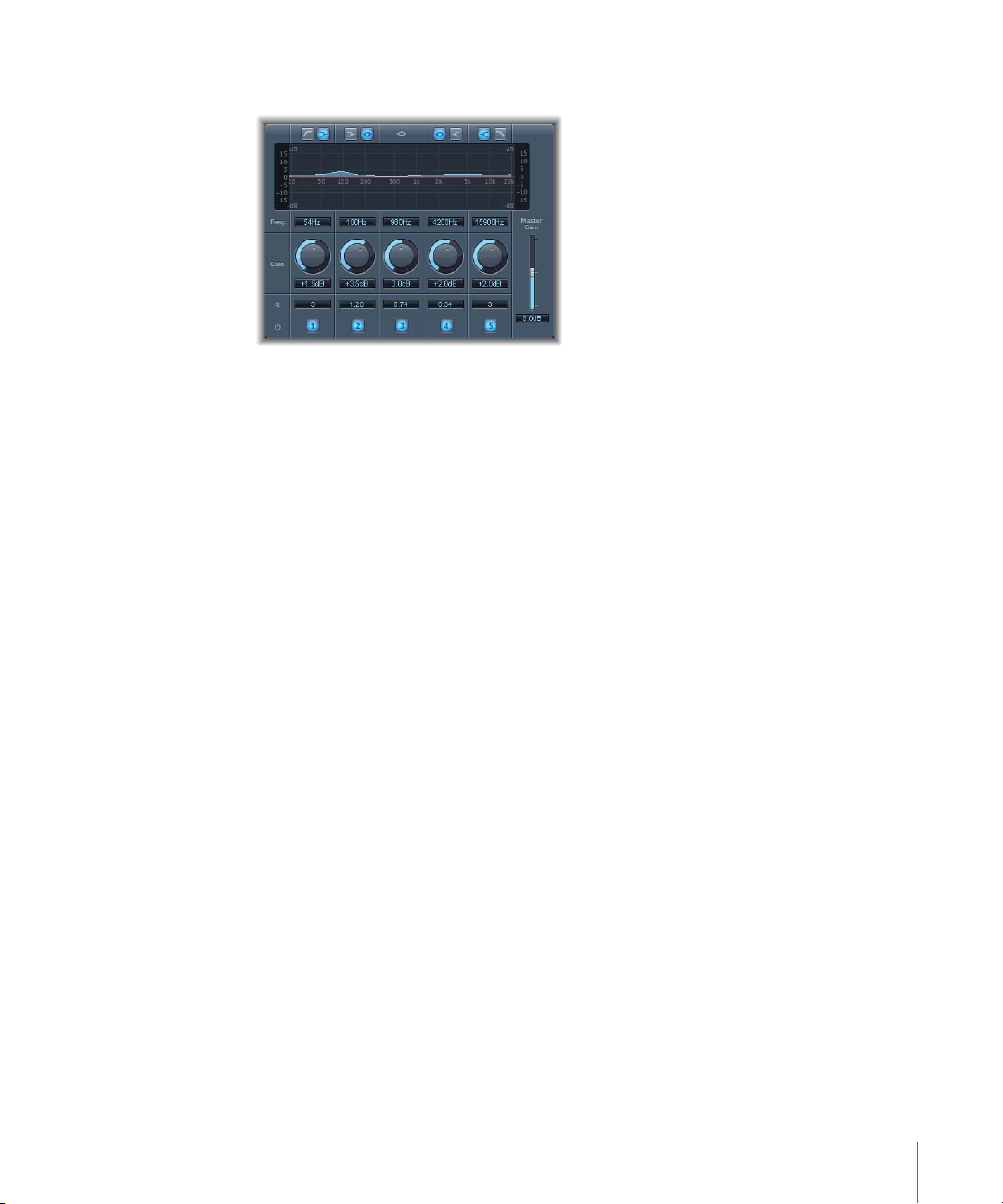
Fat EQ
The Fat EQ effect is a versatile multiband EQ with up to five individual frequency bands.
You can use Fat EQ for individual tracks or for overall mixes. The Fat EQ includes a
graphic display of the EQ curves and a set of parameters for each band.
Fat EQ Parameters
The main area of the Fat EQ window includes a graphic display area and a set of strips
with parameters for each frequency band. To the right of the parameter section are the
Master Gain slider and field.
Graphic Display Section
 Band Type buttons: Located above the graphic display. For bands 1-2 and 4-5, click
one of the pair of buttons to select the type of EQ for the corresponding band.
 For Band 1, click the highpass or the low shelving button.
 For Band 2, click the low shelving or the parametric button.
 Band 3 always acts as a parametric EQ band. (Click the button to turn it on or off.)
 For Band 4, click the parametric or the high shelving filter.
 For Band 5, click the high shelving or the lowpass button.
 Graphic display: Shows the EQ curve of each frequency band. When you adjust each
band’s settings using the controls in the Parameter section, the display reflects your
changes immediately.
Chapter 5 EQ 61
Page 62

Parameter Section
Below the graphic display area are controls that both show the settings for each band,
and which you can use to adjust each band’s settings.
 Frequency fields: Sets the frequency for each band.
 Gain knobs: Sets the amount of gain for each band.
 Q/Order fields: Sets the Q or bandwidth for each band (the range of frequencies
around the center frequency that are altered). For bands 1 and 5, this changes the
slope of the filter.
 Band On/Off buttons: Click the numbered button to turn each band on or off.
Inactive bands do not use your computer’s resources.
Master Gain Section
 Master Gain slider and field: Located to the right of the Parameter section. Sets the
output level of the signal. After boosting or cutting frequency bands, you can use the
Master Gain fader to adjust the output level.
Using the Fat EQ
The icons above the graphic display let you switch the type of EQ for each band, except
for Band 3, which always operates as a fully parametric bell filter. You can use the
controls in the Parameter section to set the frequency, gain, and Q for each band, as
well as turn individual bands on or off.
At low Q values, the EQ covers a wider frequency range, while at high Q values, the
effect of the EQ band is limited to a very narrow frequency range. Keep in mind that
the Q value can significantly influence how audible your changes are: if you’re working
with a narrow frequency band, you’ll generally need to cut or boost it more drastically
to notice the difference.
Single Band EQs
Following are descriptions of each of the effects found in the Single Band sub-menu.
High Cut and Low Cut Filter
As their names suggest, the Low Cut Filter attenuates the frequency range below the
selected frequency, while the High Cut Filter attenuates the frequency range above the
selected frequency. Each has a single parameter to set the cutoff frequency.
62 Chapter 5 EQ
Page 63

High Pass and Low Pass Filter
The High Pass Filter affects the frequency range below the set frequency. Higher
frequencies pass through the filter. You can use the High Pass Filter to eliminate the
bass below a selectable frequency. In contrast, the Low Pass Filter affects the frequency
range above the selected frequency. Both filter plug-ins offer the following parameters:
 Frequency field and slider: Sets the cutoff frequency.
 Order field and slider: Sets the filter order.
 Smoothing field and slider: Adjusts the amount of smoothing (in milliseconds).
High Shelving and Low Shelving EQ
The Low Shelving EQ only affects the frequency range below the selected frequency,
while the High Shelving EQ only affects the frequency range above the selected
frequency. Each has parameters for Gain, which you use to boost or cut the level of the
selected frequency band, and Frequency, which you use to set the cutoff frequency.
Parametric EQ
The Parametric EQ is a simple filter with a variable center frequency. It can be used to
boost or cut any frequency band in the audio spectrum, either with a wide frequency
range, or as a notch filter with a very narrow range. A symmetrical frequency range on
either side of the center frequency is boosted or cut. The Parametric EQ offers the
following parameters:
 Gain field and slider: Sets the amount of gain.
 Frequency field and slider: Sets the cutoff frequency.
 Q-Factor field and slider: Adjusts the Q (bandwidth).
Silver EQ
The Silver EQ, a Legacy effect, includes three bands: a high shelving EQ, parametric EQ,
and low shelving EQ. You can adjust the cutoff frequencies for the high and low
shelving EQs, and adjust the center frequency, gain, and Q for the parametric EQ.
Silver EQ Parameters
 High Frequency field and slider: Sets the cutoff frequency for the high shelving EQ.
 Frequency field and slider: Sets the center frequency of the parametric EQ.
 Q-Factor field and slider: Adjusts the range (bandwidth) of the parametric EQ.
 Gain field and slider: Sets the amount of gain for the parametric EQ.
 Low Frequency field and slider: Sets the cutoff frequency for the low shelving EQ.
Chapter 5 EQ 63
Page 64

Frequency Ranges Used With EQ
All sounds can be thought of as falling into one of three basic frequency ranges: bass,
midrange, or high (or treble). These can each be further divided to include low bass,
low and high midrange, and low and high highs. The following table describes some of
the sounds that fall into each range:
Name Frequency range Description
High High 8–20 kHz Includes cymbal sounds and highest harmonics of
instruments. Boosting frequencies in this range slightly can
add sparkle and presence.
High 5–8 kHz This range corresponds roughly to the treble tone control
on a stereo. Boosting frequencies in this range can add
brightness and shine.
Low High 2.5–5 kHz Includes the higher harmonics of voices and musical
instruments. This range is important for adding presence.
Excessive boosting in this range can sound shrill or harsh.
High Midrange 1.2–2.5 kHz Includes the consonants of voices and the high harmonics
of musical instruments, especially brass instruments.
Excessive boosting in this range can create a pinched, nasal
sound.
Midrange 750 Hz–1.2 kHz Includes the vowels of voices and the harmonics of musical
instruments that create tone color.
Low Midrange 250–750 Hz Includes the fundamentals and lower harmonics of voices
and musical instruments; careful EQing of each can keep
them from competing. Excessive boosting in this range can
result in muddy and unclear audio; excessive cutting can
produce thin-sounding audio.
Bass 50–250 Hz Corresponds roughly to the bass tone control on a stereo.
Includes the fundamental frequencies of voices and of
musical instruments. Excessive boosting in this range can
sound boomy and thick.
Low Bass 50 Hz and below Also called sub bass. Very little of the sound of voices or
musical instruments falls in this range. Many sound effects
used in movies, such as explosions and earthquakes, fall in
this range.
Note: The frequencies shown for each range are approximate. Any division of sound
into frequency ranges is somewhat arbitrary, and is meant only to give a general
indication of each range.
64 Chapter 5 EQ
Page 65

6 Filter
In addition to the filters of the EQ effects, you can use filters
to change the character of your audio in both familiar and
unusual ways.
The Filter sub-menu contains a variety of filter-based effects that you can use to
creatively modify your audio, including autofilters, filter banks, vocoders, wah-wah
effects, and a gate that uses frequency rather than the amplitude (volume) as the
criteria for which part of the signal is allowed to pass through.
The following sections describe the individual plug-ins included with Logic Express.
 “AutoFilter” on page 66
 “EVOC 20 Filterbank” on page 70
 “EVOC 20 TrackOscillator” on page 75
 “Fuzz-Wah” on page 85
 “Spectral Gate” on page 88
6
65
Page 66

AutoFilter
The AutoFilter is a versatile filter effect with several unique features. You can use it to
create classic, analog-style synthesizer effects, or as a tool for creative sound design.
The filter cutoff can be dynamically modulated using both a synthesizer-style ADSR
envelope and an LFO (low frequency oscillator). In addition, you can choose between
different filters types and slopes, control the amount of resonance, add distortion for
more aggressive sounds, and mix the original, dry signal with the processed signal.
AutoFilter Parameters
The main areas of the AutoFilter window include the Envelope, LFO, Filter, and
Distortion sections. The overall Threshold control is in the upper-left corner, and the
Output controls are on the right side of the window.
Threshold Slider
The Threshold slider sets the cutoff frequency—which applies to both the envelope
and LFO. When the input signal level exceeds the Threshold level, the envelope and
LFO are retriggered. The Threshold parameter always applies to the envelope. It only
applies to the LFO if the Retrigger button is selected.
Envelope Section
 Attack knob and field: Sets the attack time for the envelope.
 Decay knob and field: Sets the decay time for the envelope.
 Sustain knob and field: Sets the sustain time for the envelope.
 Release knob and field: Sets the release time for the envelope.
 Dynamic knob and field: Sets the amount by which the input signal modulates the
peak value of the envelope.
 Cutoff Mod. slider and field: Sets the intensity of the control signal’s effect on the
cutoff frequency.
66 Chapter 6 Filter
Page 67

LFO Section
 Coarse and Fine Rate knobs and field: Use together to set the frequency of the LFO.
Drag the Coarse slider to set the LFO frequency in Hertz, then drag the Fine slider to
fine tune the frequency in 1/000ths of a Hertz.
 Beat Sync button: When selected, the LFO is synchronized to the sequencer’s tempo.
 Phase knob: Lets you shift the phase relationship between the LFO and the
sequencer when Beat Sync is active.
 Decay/Delay knob and field: Sets the amount of time the LFO takes to go from 0 to its
maximum value.
 Rate Mod. knob and field: Sets the rate of modulation for the LFO frequency,
independent of the input signal level. When the input signal exceeds the Threshold,
the modulation width of the LFO increases from 0 to the Rate Mod. value.
 Stereo Phase knob and field: For stereo instances of the AutoFilter, sets the phase
relationships of the LFO modulations on the two stereo channels.
 Cutoff Mod. slider and field: Sets the intensity of the control signal’s effect on the
cutoff frequency.
 Retrigger button: When selected, the waveform starts at 0° as soon as the Threshold
is exceeded.
 Waveform buttons: Click one of the buttons to set the shape of the LFO waveform.
 Pulse Width slider and field: Lets you shape the curve of the selected waveform.
Filter Section
 Cutoff Freq. knob: Sets the cutoff frequency for the lowpass filter.
 Resonance knob: Sets the width of the frequency band around the cutoff frequency
that is emphasized.
 Fatness slider and field: Adjusts the amount of fatness (low-frequency boost). When
you set Fatness to its maximum value, adjusting Resonance has no effect on
frequencies below the cutoff frequency.
 State Variable Filter buttons: Click one of the buttons to set whether the filter is a
highpass (HP), bandpass (BP), or lowpass (LP) filter.
 4-Pole Lowpass Filter buttons: Click one of the buttons to set the slope of the lowpass
filter to 6, 12, 18, or 24 dB per octave.
Distortion Section
 Input knob: Sets the amount of distortion applied before the filter section.
 Output knob: Sets the amount of distortion applied after the filter section.
Output Section
 Dry Signal slider and field: Sets the amount of the original (dry) signal added to the
filtered signal.
 Main Out slider and field: Sets the final output volume of the AutoFilter.
Chapter 6 Filter 67
Page 68

Using the AutoFilter
The following section provides additional information on using the parameters in the
AutoFilter window.
Filter Parameters
The most important parameters are located on the right side of the AutoFilter window.
The Filter Cutoff knob determines the point where the filter kicks in. Higher frequencies
are attenuated, while lower frequencies are allowed to pass through.
The Resonance knob controls how much frequencies around the cutoff frequency are
emphasized. When you turn Resonance up sufficiently, the filter itself begins oscillating
at the cutoff frequency. Self-oscillation begins before you max out the Resonance
parameter, just like the filters on a Minimoog synthesizer. Increasing Resonance causes
the lowpass filter to cut the bottom end, making the signal sound thinner. You can
compensate for this thinness using the Fatness slider.
Both the envelope and LFO parameters are used to dynamically modulate the cutoff
frequency. The Threshold parameter at the upper-left corner of the AutoFilter window
applies to both sections, and analyzes the level of the input signal. If the input signal
level exceeds the Threshold level, the envelope and LFO are retriggered.
Envelope Parameters
When the input signal exceeds the Threshold level, the control signal is triggered at the
minimum value. Over the period of time determined by the Attack parameter, the
signal reaches its maximum level. It then decreases for the period of time defined by
the Decay value, and then stays at a constant level for the duration of the Sustain value.
Once the signal level drops below the Threshold value, it decreases to its minimum
value over the time period determined by the Release parameter. If the input signal
falls below the Threshold level before the control signal has reached the Sustain level,
the Release phase is triggered. You can modulate the peak value of the Envelope
section using the level of the input signal by adjusting the Dynamic parameter. The
Cutoff Mod. slider determines the intensity of the control signal’s effect on the cutoff
frequency.
68 Chapter 6 Filter
Page 69

LFO Parameters
You set the waveform of the LFO by clicking one of the Waveform buttons. The choices
are: descending sawtooth (saw down), ascending sawtooth (saw up), triangle, pulse
wave, or random (random values, Sample & Hold). Once you select a waveform, you
can shape the curve with the Pulsewidth slider. Use the Coarse and Fine Frequency
knobs to set the LFO frequency. The Rate Mod. (Rate Modulation) knob controls
modulation of the LFO frequency independent of the input signal level. If the input
signal exceeds the Threshold level, the modulation width of the LFO increases from 0
to the Rate Mod. value. You can also define the amount of time this process takes, by
entering the desired value with the Decay/Delay knob. If the Retrigger button is turned
on, the waveform starts at 0° whenever the Threshold is exceeded. For stereo instances
of the AutoFilter, you can control the phase relationships of the LFO modulations on
the two stereo sides with the Stereo Phase knob.
Turning on Beat Sync synchronizes the LFO to the sequencer’s tempo. The speed values
include bar values, triplet values, and more. These are determined by the Rate knob
next to the Beat Sync button. Use Sync Phase to shift the phase relationship between
the LFO and the sequencer.
Distortion Parameters
The Distortion Input and Output parameters let you individually control pre-input and
post-output distortion. Although the two distortion modules work in an identical way,
their respective positions in the signal chain—before and after the filter, respectively—
result in remarkably different sounds.
Output Parameters
The Dry Signal parameter sets the level ratio of the non-effected (dry) signal mixed
with the processed signal. The Main Out parameter can lower the output volume by as
much as 50 dB, allowing you to compensate for higher levels caused by adding
distortion or other processing.
Chapter 6 Filter 69
Page 70

EVOC 20 Filterbank
The EVOC 20 Filterbank consists of two formant filter banks, which are also used in the
EVOC 20 PolySynth vocoder plug-in.
The input signal passes through the two filter banks in parallel. Each bank features
volume faders for ten frequency bands, allowing you to adjust the volume of each
band independently. Setting a fader to its minimum value completely suppresses the
formants in that band. You can control the position and width of the filter bands using
the Formant Stretch and Formant Shift parameters. In addition, you can also crossfade
between the two filter banks.
For more information on filter banks, refer to “How Does a Filter Bank Work?” on
page 151.
EVOC 20 Filterbank Parameters
The EVOC 20 Filterbank window is divided into three main sections: the Formant Filter
section in the center of the window, the Modulation section at the bottom center, and
Output section along the right side.
70 Chapter 6 Filter
Page 71
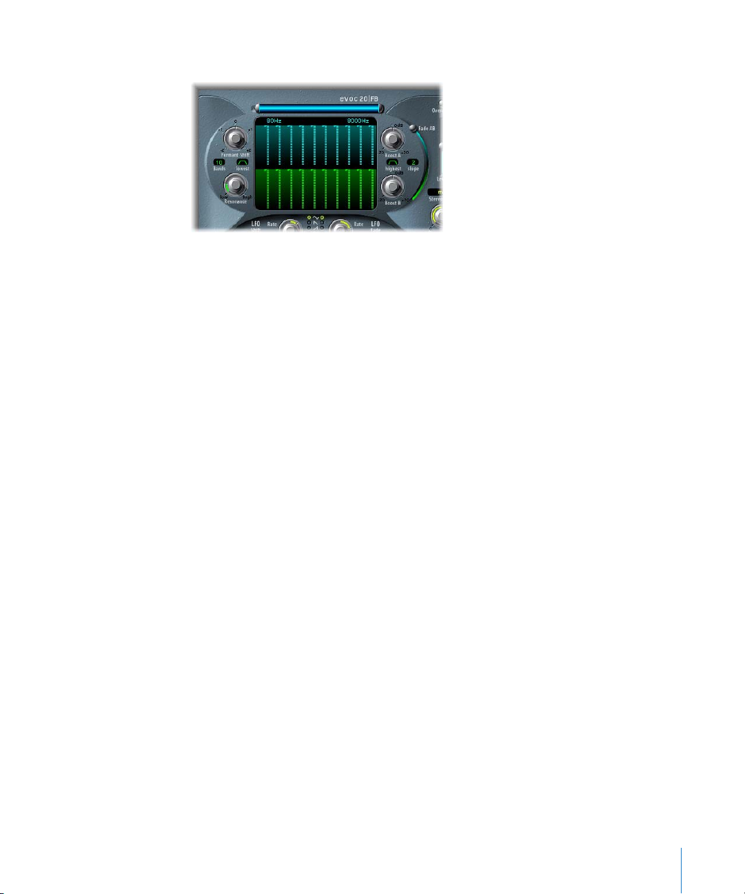
Formant Filter Section
The parameters in this section control the frequency bands in the two filter
banks: Filter Bank A and Filter Bank B.
 Frequency band faders: Set the volume of each frequency band in Filter Bank A using
the upper (blue) faders, and set the volume of each frequency band in Filter Bank B
using the lower (green) faders.
You can easily create complex bar curves by dragging horizontally across either row
of faders. This method makes editing multiple frequency band levels quick and
convenient.
 Frequency bar and fields: The blue bar above the upper row of faders controls the
overall frequency range for both filter banks. Drag the bar to move the entire
frequency range, drag the left end to move only the lower frequency (between 75
and 750 Hz), or drag the right end to move only the upper frequency (between 800
and 8000 Hz). You can also edit the numerical values above the bar directly (between
80 and 8000 Hz).
 Formant Shift knob: Moves the position of all bands in both filter banks up or down
the frequency range. You can jump directly to the values –0.5, –1, 0, +0.5 or +1.0 by
clicking one of these numbers on the edge of the knob.
 Bands value field: Sets the number of frequency bands in each filter bank. The range
is from 5 to 20 bands.
Note: Increasing the number of bands also increases the CPU overhead.
 Lowest button: Sets whether the lowest band of each filter bank acts as a lowpass or
bandpass filter.
 Resonance knob: Controls the basic sonic character of both filter banks. Increasing
the Resonance emphasizes the middle frequency of each band. Low settings give a
softer character, while high settings give a sharper character.
Chapter 6 Filter 71
Page 72

 Boost A knob: Sets the amount of boost (or cut) applied to the frequency bands in
Filter Bank A. The range is ±20 dB. This allows you to compensate for the reduction in
volume caused by lowering the level of one or more bands.
Boost is also quite handy to adjust the levels of both filter banks to each other, so
that using Fade A/B (see below) leads only to a sound color change, but not to a
level change.
 Highest button: Sets whether the highest band of each filter bank acts as a highpass
or bandpass filter.
 Slope pop-up menu: Sets the amount of filter slope applied to all filters of both filter
banks. Choices are 1 (filter attenuation of 6 dB/Oct.) and 2 (filter attenuation of 12 dB/
Oct.). 1 sounds softer, 2 sounds tighter.
 Boost B knob: Sets the amount of boost (or cut) applied to the frequency bands in
Filter Bank B. The range is ±20 dB. This allows you to compensate for the reduction in
volume caused by lowering the level of one or more bands.
 Fade AB slider: Crossfades between Filter Bank A and Filter Bank B. At the top position
(0%), only Bank A is audible, while at the bottom position (100%), only Bank B is
audible. In the middle position (50%), the banks are evenly mixed.
72 Chapter 6 Filter
Page 73

Modulation Section
The parameters in this section control the LFOs that modulate the Formant Shift and
Fade A/B parameters in the Formant Filter section, respectively. The LFO Shift
parameters on the left modulate the Formant Shift parameter of the filter bands, and
the LFO Fade parameters on the right modulate the Fade AB parameter.
 LFO Shift Intensity slider: Sets the amount by which the LFO modulates the Formant
Shift parameter.
 LFO Shift Rate knob: Sets the speed of the modulation for Formant Shift. Values to the
left of center are synchronized to the tempo in bars and other musical values, while
values to the right of center are free values in Hertz.
 Waveform buttons: Select the waveforms used by the LFO Shift and LFO Fade LFOs
respectively. From top to bottom, the available waveforms are: triangle, falling
sawtooth, rising sawtooth, square up and down around zero (bipolar), square up
from zero (unipolar), sample and hold (a random stepped waveform), and smoothed
sample and hold.
 LFO Fade Intensity slider: Sets the amount by which the LFO modulates the Fade AB
parameter.
 LFO Fade Rate knob: Sets the speed of the modulation for Fade AB. Values to the left
of center are synchronized to the tempo in bars and other musical values, while
values to the right of center are free values in Hertz.
∏ Tip: The Formant Shift and Fade LFO modulations are the keys to the most
extraordinary sounds of the EVOC 20 Filterbank: Make sure to set up either completely
different or complementary filter curves in both filter banks. You can use rhythmic
material, such as a drum loop, as an input signal, and set up tempo-synchronized
modulations with different Rates for each LFO. You can then try a tempo-synchronized
Tape Delay after the EVOC 20 Filterbank, to produce unique rhythms.
Chapter 6 Filter 73
Page 74

Output Section
The parameters in this section control the overall output of the EVOC 20 Filterbank.
 Overdrive button: Turns the overdrive circuit on or off.
Note: To hear the Overdrive effect, you may need to boost the level of one or both
filter banks.
 Level slider: Sets the level of the output signal.
Stereo Mode pop-up menu: Sets the input/output mode of the EVOC 20 Filterbank.
The choices are m/s (mono input to stereo output), and s/s (stereo input to stereo
output).
Set Stereo Mode to m/s if the input signal is mono, and to s/s if the input signal is
stereo. In s/s mode, the left and right stereo channels are processed by separate filter
banks. When using m/s mode on a stereo input signal, the signal is first summed to
mono before it is passed to the filter banks.
 Stereo Width knob: Controls how the output signals of the filter bands are distributed
in the stereo field.
 At the left position, the output of all bands are centered.
 At the centered position, the output of all bands ascends from left to right.
Â
At the right position, the bands are output evenly on the left and the right channel
The stereo/stereo mode (s/s) uses one A/B filter bank per channel. The positioning of
the frequency bands correspond to that described above, but the bands of each filter
bank ascend in opposing directions, from left to right.
.
74 Chapter 6 Filter
Page 75

EVOC 20 TrackOscillator
The EVOC 20 TrackOscillator is a vocoder with a monophonic pitch tracking oscillator.
The tracking oscillator allows the EVOC 20 TrackOscillator to track (follow) the pitch of a
mono input signal. For example, if the input signal is a vocal melody, the individual
pitches of the sung notes will be tracked and mirrored by the synthesis engine.
The EVOC 20 TrackOscillator features two formant filter banks, an analysis and a
synthesis filter bank. Each has several (configurable) input parameters. You can use the
track into which the EVOC is inserted as the analysis signal source, or use another audio
track as the input source via a Side Chain. The synthesis source can be the track into
which the EVOC is inserted, another audio track, or the tracking oscillator. Each analysis
frequency band has an envelope follower that tracks the level of that band, so that it
can be remodeled more precisely.
The signal path of the EVOC 20 TrackOscillator is shown in the block diagram on page
168.
∏ Tip: For good pitch tracking, it is essential to use a mono signal (with no overlap of
pitches) that is as unprocessed as possible. Avoid using a signal with background
noises. Using a signal processed with even a slight amount of reverb, for example, will
produce strange (and likely undesirable) results. Even stranger results will result when a
signal with no audible pitch (such as drum loop) is used. In some situations, however,
the resulting artifacts might be desirable.
The EVOC 20 TrackOscillator is not limited to pitch tracking effects. It can vocode a
signal by itself, making it very useful for unusual filter effects. Try this with different
Resonance, Formant Shift, and Formant Stretch settings. As both analysis and synthesis
input signals are freely selectable, you can even vocode an orchestra with train noises,
for example.
More information about vocoders can be found in “Vocoder Basics” on page 150.
Chapter 6 Filter 75
Page 76
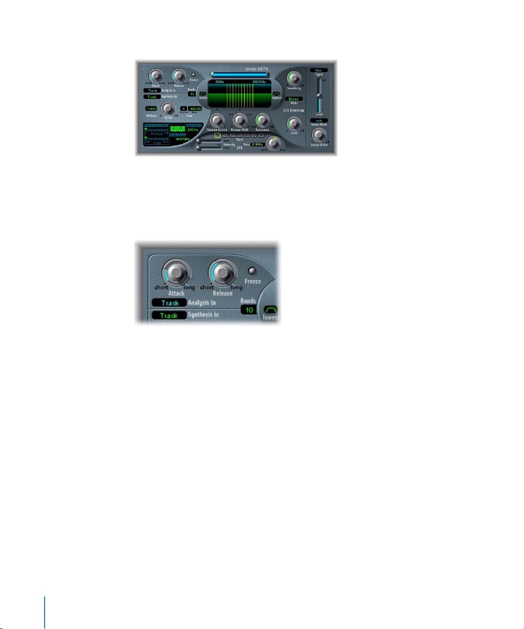
EVOC 20 TrackOscillator Parameters
The EVOC 20 TrackOscillator window is divided into the following sections, from left to
right: Analysis In, Synthesis In, Tracking Oscillator, Formant Filter, LFO, U/V Detection
and Output.
Analysis In Section
The parameters in section control various aspects of the analysis signal.
 Attack knob: Controls how quickly the envelope follower coupled to each analysis
filter band reacts to rising signals. Longer Attack times result in a slower tracking
response to transients of the analysis input signal.
Note: A long attack time on percussive input signals (such as spoken word or hi-hat
parts) results in a less articulated vocoder effect. Set Attack as low as possible to
achieve precise articulation.
 Release knob: Controls how quickly the envelope follower coupled to each analysis
filter band reacts to falling signals. Longer release times make transients of the
analysis input signal sound for a longer period of time at the Vocoder’s output.
Note: A long release time on percussive input signals results in a less articulated
vocoder effect. Release times that are too short result in rough, grainy vocoder
sounds. Release values of around 8 to 10 ms are a useful starting point.
76 Chapter 6 Filter
Page 77

 Freeze button: When selected, the current analysis sound spectrum is held
indefinitely. This can capture a particular characteristic of the source signal, which is
then imposed as a complex sustained filter shape on the Synthesis section. While
Freeze is selected, the analysis filter bank ignores the input source, and the Attack
and Release parameters have no effect.
Using a spoken word pattern as a source, for example, the Freeze parameter can
capture the attack or tail phase of an individual word within the pattern; for example
a vowel sound.
Another use of the Freeze parameter is to compensate for people’s inability to
sustain sung notes for a long period without taking a breath. If you wish the
synthesis signal to be sustained when the analysis source signal is not, Freeze can be
used to lock the current formant levels (of a sung note), even during gaps in the
vocal part, such as between words in a vocal phrase.
 Analysis In pop-up menu: Sets the analysis signal source. The choices are:
 Track: Sets the audio track into which the EVOC 20 TrackOscillator is inserted as
the analysis signal.
 Side Chain: Sets the Side Chain (another audio track) as the analysis signal. You
choose the Side Chain source track from the Side Chain pop-up menu at the top of
the EVOC 20 TrackOscillator window.
Note: If Side Chain is selected, and no Side Chain track is assigned, the track’s signal is
used as the analysis source.
Chapter 6 Filter 77
Page 78

Synthesis In Section
The parameters in section control various aspects of the synthesis signal.
 Synthesis In pop-up menu: Sets the synthesis signal source. The choices are:
 Oscillator (Osc.): Sets the tracking oscillator as the synthesis source. The oscillator
tracks the pitch of the analysis input signal. Choosing Osc. activates the other
parameters in the Synthesis section. If Osc is not chosen, the FM Ratio, FM Int, and
other parameters in this section have no effect.
Â
Track: Sets the audio track into which the EVOC 20 TrackOscillator is inserted as the
synthesis source signal.
 Side Chain (SideCh): Sets the Side Chain (another audio track) as the synthesis
source signal. You choose the Side Chain source track from the Side Chain pop-up
menu at the top of the EVOC 20 TrackOscillator window.
Note: If Side Chain is selected, and no Side Chain track is assigned, the track’s signal
is used as the synthesis source.
 Bands value field: Sets the number of frequency bands used by the
EVOC 20 TrackOscillator filter banks. The range is from 5 to 20. The greater the
number of bands, the more precisely the sound can be reshaped. Increasing the
number of bands also increases the CPU overhead.
Tracking Oscillator
The parameters in the Tracking Oscillator section control various aspects of the tracking
oscillator.
The FM tone generator for the tracking oscillator consists of two oscillators, each of
which generates a sine wave. The frequency of Oscillator 1 (the carrier) is linearly
modulated by Oscillator 2 (the modulator), which deforms the sine wave of Oscillator 1
to a waveform with a rich harmonic structure.
The FM Int control determines whether the tracking oscillators delivers a sawtooth
wave or the signal of an FM tone generator.
78 Chapter 6 Filter
Page 79

 FM Ratio knob: Sets the ratio between Oscillators 1 and 2, which defines the basic
character of the sound. Even-numbered values (or their multiples) produce harmonic
sounds are produced, while odd-numbered values (or their multiples) produce
inharmonic, metallic sounds.
 An FM Ratio of 1.000 produces results resembling a sawtooth waveform.
 An FM Ratio of 2.000 produces results resembling a square wave with a pulse
width of 50%.
 An FM Ratio of 3.000 produces results resembling a square wave with a pulse
width of 33%.
 FM Int knob: Selects the basic waveform and controls the intensity of FM modulation.
 At a value of 0, the FM tone generator is disabled, and a sawtooth wave is
generated instead.
 For values higher than 0, the FM tone generator is activated. Higher values result in
a more complex and brighter sound.
 Coarse Tune value field: Sets the pitch offset of the oscillator in semitones, up to
±2 octaves.
 Fine Tune value field: Sets the pitch offset in cents. The default value is concert pitch A
= 440 Hz. The range is from 425.00 to 455.00 Hz.
The Pitch Quantize, Root/Scale, and Max Track controls, in conjunction with the piano
keys of the onscreen keyboard, control the automatic pitch correction facility (Pitch
Quantize) of the tracking oscillator. Pitch Quantize, in conjunction with the Root/Scale
and Max Track parameters, can be used to constrain the pitch of the tracking oscillator
to a scale or chord. This allows subtle or savage pitch corrections, and can be used
creatively on unpitched material with high harmonic content, such as cymbals and
high-hats. To use pitch quantization, the Strength parameter must be set above a value
of zero, and at least one of the onscreen keyboard keys needs to be activated.
 Pitch Quantize Strength slider: Determines how pronounced the automatic pitch
correction is.
 Pitch Quantize Glide slider: Sets the amount of time the pitch correction takes,
allowing sliding transitions to the quantized pitches.
 Root/Scale Keyboard and pop-up menu: Use together to define the pitch or pitches to
which the tracking oscillator is quantized, as described below:
Chapter 6 Filter 79
Page 80

 Click the value below the word Scale to display the Root/Scale pop-up menu.
 Choose the scale or chord to use as the basis for pitch correction from the pop-up
menu.
 Set the root key of the respective scale or chord by vertically dragging the Root
parameter, or double-click and enter a root between C and B. The Root parameter
is not available when the Root/Scale value is chromatic or user.
 You can add notes to the chosen scale or chord by clicking keys on the small
keyboard, and remove notes by clicking notes already selected. Selected notes
appear bright green. Selecting any notes sets the Root/Scale value to user.
 Your last edit is remembered. If you choose a new scale or chord, but do not make
any changes, you can jump back to the previously set user scale.
You can automate the Root and Scale parameters and the keys of the onscreen
keyboard in Logic Express.
 Max Track value field: Sets the frequency above which the high frequencies of the
analysis signal are cut, making the pitch detection more robust. Should the pitch
detection produce unstable results, reduce the Max Track parameter value to the
lowest possible setting.
Formant Filter Section
The parameters in section control the two formant filter banks of the
EVOC 20 TrackOscillator.
 Formant Filter graphic display: Shows the frequency bands for the analysis and
synthesis parameters.
The Formant Filter display is divided into two sections by a horizontal line. The upper
half applies to the Analysis section and the lower half to the Synthesis section.
Changes made to the High/Low frequency parameters, the Bands parameter or the
Formant Stretch and Formant Shift parameters will result in visual changes to the
Formant Filter display. This provides you with invaluable feedback on what is
happening to the signal as it is routed through the two formant filter banks.
80 Chapter 6 Filter
Page 81

 Frequency bar and fields: The blue bar above the upper row of faders controls the
upper and lower frequencies for both filter banks. Drag the bar to move both the
upper and lower frequencies, drag the left end to move only the lower frequency
(the value range is 75 to 750 Hz), or drag the right end to move only the upper
frequency (the value range is 800 to 8000 Hz). You can also edit the numerical values
above the bar directly (between 80 and 8000 Hz).
 Lowest button: Sets whether the lowest band of each filter bank acts as a lowpass or
bandpass filter.
 Highest button: Sets whether the lowest band of each filter bank acts as a highpass
or bandpass filter.
 Formant Stretch knob: Alters the width and distribution of the bands in the synthesis
filter bank, extending or narrowing the frequency range defined by the blue bar
(Low/High frequency parameters) for the synthesis filter bank.
If Formant Stretch is set to 0, the width and distribution of the bands in the synthesis
filter bank is equal to the width of the bands in the analysis filter bank. Low values
narrow the width of each band, while high values widen it. The control range is from
0.5 to 2 (as a ratio of the overall bandwidth).
Note: You can jump directly to a value of 1 by clicking on its number.
 Formant Shift knob: Shifts the position of the bands in the synthesis filter bank up or
down. When set to 0, the position of the bands in the synthesis filter bank is equal to
the position of the bands in the analysis filter bank. Positive values will move the
bands up in frequency, while negative values will move them down in respect to the
analysis filter bank. You can jump directly to the values –0.5, –1, 0, +0.5 and +1 by
clicking on their numbers.
∏ Tip: When combined, Formant Stretch and Formant Shift alter the formant structure of
the resulting vocoder sound, and can result in some interesting timbre changes. As an
example, using speech signals and tuning Formant Shift up results in Mickey Mouse
effects. Formant Stretch and Formant Shift are especially useful if the frequency
spectrum of the synthesis signal does not complement the frequency spectrum of the
analysis signal. You could create a synthesis signal in the high frequency range from an
analysis signal which mainly modulates the sound in a lower frequency range, for
example.
 Resonance knob: Controls the basic sonic character of both filter banks. Increasing
the Resonance emphasizes the middle frequency of each band. Low settings give a
softer character, while high settings give a sharper character.
Note: The use of either, or both, of the Formant Stretch and Formant Shift
parameters can result in the generation of unusual resonant frequencies when high
Resonance settings are used.
Chapter 6 Filter 81
Page 82

LFO Section
The parameters in this section control the LFO that can be used to modulate either the
frequency (Pitch) of the tracking oscillator (vibrato), or the Formant Shift (Shift)
parameter of the synthesis filter bank.
It allows synchronous/non-synchronous modulation in bar, beat (triplet) or free values.
 Wave buttons: Select the waveform used by the LFO. A selection of Triangle, falling
and rising Sawtooth, Square up and down around zero (bipolar, good for trills),
Square up from zero (unipolar, good for changing between two definable pitches), a
random stepped waveform (S&H), and a smoothed random waveform is available.
Simply click on the appropriate button to select a waveform type.
 LFO Formant Shift Intensity slider: Controls the amount of format shift by the LFO.
 LFO Pitch Intensity: Controls the amount of modulation (vibrato) by the LFO.
 LFO Rate knob and field: Sets the speed of the LFO modulation. Values to the left of
the center positions are synchronized with the sequencer’s tempo and include bar
values, triplet values and more. Values to the right of the center positions are nonsynchronous and displayed in Hertz (cycles per second).
Note: The ability to use synchronous bar values could be used to perform a formant
shift every four bars on a one bar percussion part which is being cycled. Alternately,
you could perform the same formant shift on every eighth note triplet within the
same part. Either method can generate interesting results, and can lead to new ideas,
or a new lease of life for existing audio material.
82 Chapter 6 Filter
Page 83

U/V Detection Section
The U/V Detection section detects the unvoiced portions of the sound in the analysis
signal, improving speech intelligibility. Please refer to “Unvoiced/Voiced (U/V)
Detection” on page 165, for a full explanation of the U/V Detection principle. More
information about improving speech intelligibility can be found in “Tips for Better
Speech Intelligibility” on page 169.
 Sensitivity knob: Sets the degree of responsiveness of U/V detection. By turning this
knob to the right, more of the individual unvoiced portions of the input signal are
recognized.
When high settings are used, the increased sensitivity to unvoiced signals can lead to
the U/V source—determined by the Mode parameter—being used on the majority
of the input signal, including voiced signals. Sonically, this results in a sound that
resembles a radio signal which is breaking up and contains a lot of static or noise.
 Mode pop-up menu: Choose the sound source(s) which can be used to replace the
unvoiced content of the input signal. The choices are: Off, Noise, Noise + Synth, or
Blend.
 Noise: Uses noise alone for the unvoiced portions of the sound.
 Noise + Synth: Uses noise and the synthesizer for the unvoiced portions of the sound.
 Blend: Uses the analysis signal after it has passed through a highpass filter, for the
unvoiced portions of the sound. This filtered analysis signal is then mixed with the
EVOC 20 TrackOscillator output signal. The Sensitivity parameter has no effect on
this setting.
Chapter 6 Filter 83
Page 84

 Level slider: Controls the amount of the signal (Noise, Noise + Synth, or Blend) used
to replace the unvoiced content of the input signal.
Warning: Care should be taken with this control, particularly when a high Sensitivity
value is used, to avoid internally overloading the EVOC 20 TrackOscillator.
Output Section
 Signal pop-up menu: Choose the signal to send to the EVOC 20 TrackOscillator’s main
outputs. The choices are: Voc(oder), Syn(thesis), and Ana(lysis). To hear the vocoder
effect, choose Voc. The other two settings are useful for monitoring purposes.
 Level slider: Sets the level of the output signal.
 Stereo Mode pop-up menu: Sets the input/output mode of the EVOC 20 Filterbank.
The choices are m/s (mono input to stereo output), and s/s (stereo input to stereo
output).
Set Stereo Mode to m/s if the input signal is mono, and to s/s if the input signal is
stereo. In s/s mode, the left and right stereo channels are processed by separate filter
banks. When using m/s mode on a stereo input signal, the signal is first summed to
mono before it is passed to the filter banks.
84 Chapter 6 Filter
Page 85

 Stereo Width knob: Controls how the output signals of the filter bands are distributed
in the stereo field.
 At the left position, the output of all bands are centered.
 At the centered position, the output of all bands ascends from left to right.
 At the right position, the bands are output evenly on the left and the right channel.
The stereo/stereo mode (s/s) uses one A/B filter bank per channel. The positioning of
the frequency bands correspond to that described above, but the bands of each filter
bank ascend in opposing directions, from left to right.
Fuzz-Wah
The Fuzz-Wah emulates classic wah effects often used with a Clavinet, and adds
compression and fuzz distortion effects as well.
Parameters of the Fuzz-Wah
 Effect Order buttons: Select whether the wah effect precedes the fuzz effect in the
signal chain (Wah-Fuzz), or vice versa (Fuzz-Wah).
The integrated compressor always precedes the fuzz effect. When Wah-Fuzz is
selected, the compressor comes between the wah and the fuzz effect; conversely,
when Fuzz-Wah is selected, the compressor comes first in the signal chain.
Chapter 6 Filter 85
Page 86

Wah Section
 Wah Mode pop-up menu: Choose one of the six modes, which emulate various classic
wah effects and filter types, or choose off.
 Auto Gain button: The wah effect can cause the output level to vary widely. Turning
Auto Gain On compensates for this tendency, and keeps the output signal within a
more stable range.
 Wah Level knob: Sets the amount of the wah-filtered signal.
 Relative Q slider: Adjusts the sharpness of the wah sweep by raising or lowering the
filter peak. A setting of 0 (zero) retains the original peak level for each mode.
 Pedal Range slider: Sets the sweep range of the wah filter controlled using a MIDI
foot pedal, letting you compensate for the difference in mechanical range between a
MIDI foot pedal and a classic wah pedal.
You can set the upper and lower limits of the range independently by dragging the
left and right edges of the Pedal Range slider, or move the entire range at once by
dragging the center section of the slider. Press the normalize button to reset the
pedal range to its default values.
AutoWah Section
 Depth knob: Sets the depth of the autowah effect.
 Attack knob: Sets the time it takes for the wah filter to fully open.
 Release knob: Sets the time it takes for the wah filter to close.
Fuzz Section
 Comp (Compression) Ratio knob: Sets the compression ratio of the integrated
compressor.
 Fuzz Gain knob: Sets the level of distortion for the fuzz effect between 0 dB and
20 dB.
 Fuzz Tone knob: Adjusts the tone of the fuzz effect between 2 kHz and 20 kHz.
AutoWah Attack/Release
These parameters allow you to define how much time it takes for the Wah filter to open
and close. Range (in milliseconds): 10 to 10,000
86 Chapter 6 Filter
Page 87

Using the Fuzz-Wah
The following sections cover various aspects of the Fuzz-Wah parameters.
Setting the Wah Level With Auto Gain
The wah effect can cause the output level to vary widely. Turning Auto Gain on
compensates for this tendency, and keeps the output signal within a more stable
range.
To hear the difference Auto Gain can make:
1 Switch Auto Gain to on.
2 Raise the effect level to a value just below the mixer’s clipping limit.
3 Make a sweep with a high relative Q setting.
4 Switch Auto Gain to off, and repeat the sweep.
Warning: Please take care while doing this, or your ears and speaker system may be
damaged.
AutoWah Depth
In addition to using MIDI foot pedals (see above), the wah effect can be controlled
using the Auto Wah facility. The sensitivity of the Auto Wah can be set with the Depth
parameter. Range: 0.00 to 100.
Relative Q
The quality of the main filter peak can be increased/decreased, relative to the model
setting, thereby obtaining a sharper/softer wah sweep. When set to a value of 0, the
original setting of the model is active. Range: –1.00 to +1.00 (0.00 is the default)
Setting the Pedal Range
Common MIDI foot pedals have a much larger mechanical range than most classic Wah
pedals.
The exact sweep range of the wah filter effected by the MIDI foot pedal is set with the
Pedal Range parameters. The highest and lowest possible value reached by the pedal is
graphically represented by a gray bracket around the Pedal Position fader (represents
the current position of the Wah pedal). The left and right limit is set by clicking and
moving it with the mouse. Both values can be moved simultaneously by clicking in the
center of the bracket and moving it to the left or right.
Chapter 6 Filter 87
Page 88

Spectral Gate
The Spectral Gate separates the signal above and below the Threshold level into two
independent frequency ranges—that you can modulate separately. It can produce
some unusual and rich filtering effects.
Spectral Gate Parameters
 Threshold slider and field: Sets the threshold level at which the frequency band
defined by the Center Freq. and Bandwidth parameters is divided into upper and
lower frequency ranges.
 Speed slider and field: Sets the modulation frequency for the defined frequency band.
 CF (Center Frequency) Modulation slider and field: Sets the intensity of center
frequency modulation.
 BW (Band Width) Modulation slider and field: Sets the amount of bandwidth
modulation.
 Graphic display: Shows the frequency band defined by the Center Freq. and
Bandwidth parameters.
 Center Freq. (Frequency) knob and field: Sets the center frequency of the frequency
band to be processed by the Spectral Gate.
 Bandwidth knob and field: Sets the bandwidth of the frequency band to be
processed by the Spectral Gate.
 Low Level slider and field: Blends the frequencies of the original signal below the
selected frequency band with the processed signal.
 Super Energy knob and field: Controls the level of the frequency range above the
threshold.
 Sub Energy and field: Controls the level of the frequency range below the threshold.
 High Level slider and field: Blends the frequencies of the original signal above the
selected frequency band with the processed signal.
 Gain slider and field: Adjusts the amount of gain for the final output signal.
88 Chapter 6 Filter
Page 89

Using the Spectral Gate
Using the Center Freq. and Bandwidth parameters, set the frequency band you want to
process using the Spectral Gate. The graphic display visually indicates the band defined
by these two parameters.
Once the frequency band is defined, use the Threshold parameter to set the level
above and below which the frequency band is divided into upper and lower ranges.
Use the Super Energy knob to control the level of the frequencies above the Threshold,
and use the Sub Energy knob to control the level of the frequencies below the
Threshold.
You can also mix the frequencies from the original signal outside the frequency band
defined by the Center Freq. and Bandwidth with the processed signal. Use the Low
Level slider to blend the bass frequencies below the defined frequency band with the
processed signal, and use the High Level slider to blend in frequencies above the
defined frequency band.
You can modulate the defined frequency band using the Speed, CF Modulation, and
BW Modulation parameters. Speed determines the modulation frequency, CF (Center
Frequency) Modulation defines the intensity of the center frequency modulation, and
BW (Band Width) Modulation controls the bandwidth modulation.
After making your adjustments, you can use the Gain slider to adjust the final output
level of the processed signal.
One way to get better acquainted with the operation of the Spectral Gate would be to
start with a drum loop. Set the Center Freq. to its minimum (20 Hz) and the Bandwidth
to its maximum (20000 Hz) value (so that the entire frequency range is processed). Turn
up the Super Energy and Sub Energy knobs, one at a time, then try different Threshold
settings. This should give you a good sense of how different Threshold levels affect the
sound of Super Energy and Sub Energy. When you come across a sound that you like or
consider useful, narrow the Bandwidth drastically, gradually increase the Center Freq.,
and then use the Low Level and High Level sliders to mix in some treble and bass from
the original signal. At lower Speed settings, turn up the CF Mod. or BW Mod. knobs.
Chapter 6 Filter 89
Page 90

Page 91

7 Imaging
You can use the Logic Express Imaging plug-ins to extend
the stereo base of a recording, and to alter perceived signal
positions.
These effects enable you to make certain sounds, or the overall mix, seem wider and
more spacious. You can also alter the phase of individual sounds within a mix, to
enhance or suppress particular transients.
The following sections describe the Imaging plug-ins included with Logic Express:
 “Direction Mixer” on page 91.
 “Stereo Spread” on page 94.
7
Direction Mixer
You can use the Direction Mixer plug-in to decode middle and side (MS) audio
recordings (see “What Is MS?” on page 93), or to spread the stereo base of a (left/right)
recording, and determine its pan position.
 Input buttons: Use the LR or MS buttons to determine whether the input signal is a
standard left/right signal, or if you’re dealing with an MS encoded (middle and side)
signal.
 Spread slider and field: Determines the spread of the stereo base.
 Direction knob and field: Determines the direction from which the middle of the
recorded stereo signal will emanate from within the mix, or in less complicated
terms, its pan position.
91
Page 92

Using the Direction Mixer
The Direction Mixer is a simple plug-in to use, as it only offers two parameters: Spread
and Direction. Each alters the incoming signal differently when either the LR or MS
Input buttons are active.
Using the Spread Parameter on LR Input Signals
At a neutral value of 1, the left side of the signal is positioned precisely on the left, and
the right side precisely on the right. As you decrease the Spread value, the two sides
move towards the center of the stereo image. A value of 0 produces a mono signal
(both sides of the input signal are routed to the two outputs at the same level—a true
middle signal). At values greater than 1, the stereo base is extended out to an
imaginary point beyond the spatial limits of the speakers.
Note: If simply using the Direction Mixer to spread the stereo base, monaural
compatibility decreases with Spread values above 1. Once a stereo signal has been
processed at an extreme Spread setting of 2, the signal will be canceled out completely
if played back in mono—after all, L–R plus R–L doesn’t leave you with much.
Using the Spread Parameter on MS Input Signals
When you alter MS levels with the Spread parameter (above a value of 1), the level of
the side signal becomes higher than that of the middle signal. At a value of 2, you will
only hear the side signal (on the left, you’ll hear L–R and on the right, R–L).
Setting the Direction Parameter
When Direction is set to a value of 0, the middle of the stereo recording will be dead
center within the mix. If you use positive values, the midpoint of the stereo recording is
moved towards the left. Negative values move the midpoint to the right. Here’s how
this works:
 At 90˚, the midpoint of the stereo recording is panned hard left.
 At –90˚, the midpoint of the stereo recording is panned hard right.
 Higher values move the midpoint back towards the center of the stereo mix, but this
also has the effect of swapping the stereo sides of the recording. To explain: At
values of 180˚ or –180˚, the midpoint of the recording is dead center in the mix, but
the left and right sides of the recording are swapped.
92 Chapter 7 Imaging
Page 93

What Is MS?
Relegated to obscurity for a good long while, MS stereo (middle-side as opposed to
left-right) has recently enjoyed a renaissance of sorts.
Making a Middle Side Recording
Two microphones are positioned as closely together as possible (usually on a stand or
hung from the studio ceiling). One is a cardioid (or omnidirectional) microphone which
directly faces the sound source that you want to record—in a straight alignment. The
other is a bidirectional microphone, with its axes pointing to the left and right (of the
sound source) at 90˚ angles.
 The cardioid microphone records the middle signal to the left side of a stereo track.
Â
The bidirectional microphone records the side signal to the right side of a stereo track.
MS recordings made in this way can be decoded by the Direction Mixer.
Why Make MS Recordings?
The advantage that MS recordings have over XY recordings (two cardioid microphones
that are directed to a point halfway to the left and right of the sound source) is that the
stereo middle is actually located on the on-axis (main recording direction) of the
cardioid microphone. This means that slight fluctuations in frequency response that
occur off the on-axis—as is the case with every microphone—are less troublesome.
In principle, MS and LR signals are equivalent, and can be converted at any time. When
“–” signifies a phase inversion, then the following applies:
M = L+R
S = L–R
In addition, L can also be derived from the sum of—and R, from the difference
between—M and S.
Here’s some interesting trivia for you: Radio (FM) broadcasts feature M and S stereo.
The MS signal is actually converted to a signal suitable for the left and right speakers by
the receiver.
Chapter 7 Imaging 93
Page 94
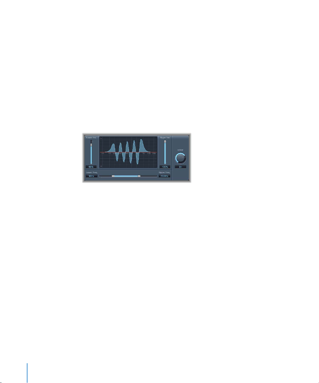
Stereo Spread
The Stereo Spread effect is typically used for mastering. There are several ways to
extend the stereo base (or perception of space), including use of reverbs and other
effects, and altering the signal’s phase. They can all sound great, but can also weaken
the overall sound of your mix by ruining transient responses, for example.
The Stereo Spread plug-in extends the stereo base by distributing a (selectable)
number of frequency bands from the middle frequency range to the left and right
channels. This is done alternately—middle frequencies to the left channel, middle
frequencies to the right channel, and so on. This greatly increases the perception of
stereo width without making the sound totally unnatural, especially when used on
mono recordings.
Stereo Spread Parameters
 Lower Int. slider and field: Sets the amount of stereo base extension for the lower
frequency bands.
 Upper Int. slider and field: Sets the amount of stereo base extension for the upper
frequency bands.
A point to note when you are setting the Lower and Upper Int. sliders is that the
stereo effect is most apparent in the middle and higher frequencies, and that
distributing low frequencies between the left and right speakers significantly reduces
the energy from both speakers. For this reason, you should use a lower Lower Int.
setting, and avoid setting the Lower Freq. below 300 Hz.
 Graphic display: Shows the number of bands the signal is divided into, and the
intensity of the Stereo Spread effect in the upper and lower frequency bands. The
upper section represents the left channel, and the lower section represents the right
channel. The frequency scale displays frequencies in ascending order, from left to
right.
 Upper and Lower Freq. slider and fields: Use these to determine the upper and lower
limits of the highest frequency, and lowest band, to be distributed in the stereo
image.
 Order knob: Sets the number of frequency bands that the signal is divided into. A
value of 8n is usually sufficient for most tasks, but you can use up to 12 bands.
94 Chapter 7 Imaging
Page 95

8 Metering
8
You can use the Metering plug-ins of Logic Express to analyze
audio in a variety of ways.
Each Metering plug-in allows you to view different characteristics of an audio signal. As
examples: The BPM Counter displays the tempo of an audio file, the Correlation Meter
displays the phase relationship, and the Level Meter displays the level of an audio
recording.
This chapter describes the Metering plug-ins included with Logic Express:
 “BPM Counter” on page 96
 “Correlation Meter” on page 97
 “Level Meter” on page 97
 “Tuner” on page 98
95
Page 96

BPM Counter
You can use the BPM Counter to analyze the tempo of an audio track. Insert the plug-in
into a track, to analyze the dynamic events of the audio signal.
The detection circuit looks for any transients in the input signal. Transients are very fast,
non-periodic sound events in the attack portion of the signal. The more obvious this
impulse is, the easier it is for the BPM Counter to detect the tempo. As a result,
percussive drum and instrumental rhythm tracks (basslines, for example) are very well
suited for tempo analysis. Pad sounds are a poor choice.
The LED shows the current analysis status. If the LED is flashing, a tempo measurement
is taking place. When lit, analysis is complete, and the tempo is displayed. The
measurement ranges from 80 to 160 beats per minute. The measured value is displayed
with an accuracy of one decimal place.
The BPM Counter also detects any tempo variation in the signal, and tries to analyze it/
them accurately. If the LED starts flashing during playback, this indicates that the BPM
Counter has detected a tempo that has deviated from the last received (or set) tempo.
As soon as a new, constant tempo is recognized, the LED will be solidly lit.
Click the LED to reset the BPM Counter.
96 Chapter 8 Metering
Page 97

Correlation Meter
The Correlation Meter displays the phase relationship of a stereo signal.
 A correlation of +1 (plus one, the far right position) means that the left and right
channels correlate 100% (they are completely in-phase).
 A correlation of 0 (zero, the center position) indicates the widest permissible left/
right divergence, often audible as an extremely wide stereo effect.
 Correlation values lower than zero indicate that out-of-phase material is present,
which can lead to phase cancellations if the stereo signal is combined into a
monaural signal.
Level Meter
The Level Meter displays the current signal level on a decibel scale. The signal level for
each channel is represented by a blue bar. When the level exceeds 0 dB, the portion of
the bar above the 0 dB point becomes red. Stereo instances of the Level Meter show
independent left and right bars, while mono instances display only a single bar.
The current peak values are displayed numerically, superimposed over the graphic
display. You can reset these values by clicking in the display.
The Level Meter can be set to display levels using Peak, RMS, or Peak & RMS
characteristics. Simply choose the desired setting in the pop-up menu (below the
graphic display). RMS levels appear as dark blue bars. Peak levels appear as light blue
bars. You can also choose to view both Peak and RMS levels simultaneously.
Chapter 8 Metering 97
Page 98

Tuner
You can tune both acoustic and electric musical instruments connected to your system
using the Tuner. Tuning your instruments ensures that your recordings will be in tune
with any software instruments, existing samples, or existing recordings in your projects.
Tuner Parameters
 Graphic tuning display: As you play, the pitch of the note appears in the semicircular
area, centered around the Keynote. If the highlight bar moves to the left of center,
the note is flat; if the highlight bar moves to the right of center, the note is sharp. The
numbers around the edge of the display show the variance, in cents, from the target
pitch.
 Keynote/Octave display: The upper Keynote area shows the target pitch of the note
you play (the closest pitch in tune). The lower Octave area indicates which octave the
note belongs to. This matches the MIDI octave scale, with the C above middle C
displayed as C4, and middle C displayed as C3.
 Tuning Adjustment knob and field: Sets the pitch of the note used as the basis for
tuning. By default, the Tuner is set to concert pitch A = 440 Hz. Drag the knob left to
lower the pitch corresponding to A, or drag the knob right to raise the pitch
corresponding to A. The current value is displayed in the field.
Using the Tuner
Using the Tuner is simple. With your instrument (or microphone capturing the sound of
an acoustic instrument) connected to the channel with the Tuner, play a single note
and watch the display. If the note is flat of the Keynote, the segments left of center
light, showing how far (in cents) the note is off pitch. If the note is sharp, the midpoint
segments right of center light. Adjust the tuning of your instrument until the center
segment lights (red).
On the tuning display, the range is marked in single semitone steps ±6 cents close to
the center, and then in larger increments to a maximum of ±50 cents.
98 Chapter 8 Metering
Page 99

9 Modulation
9
Modulation effects are used to add motion and depth to your
sound.
Modulation effects include chorus, flanging, and phasing among others, which make
sounds richer or more animated. This is often achieved through the use of an LFO,
which is controlled with parameters such as speed or frequency, and depth (also called
width, amount, or intensity). You can also control the ratio of the affected (wet) signal
and the original (dry) signal. Some modulation effects include feedback parameters,
which add part of the effect’s output back into the effect input.
Logic Express includes the following modulation effects:
 “Chorus” on page 100
 “Ensemble” on page 100
 “Flanger” on page 101
 “Microphaser” on page 102
 “Modulation Delay” on page 102
 “Phaser” on page 103
 “Ringshifter” on page 105
 “Rotor Cabinet” on page 110
 “Scanner Vibrato” on page 112
 “Spreader” on page 113
 “Tremolo” on page 114
99
Page 100

Chorus
The Chorus effect delays the original signal. The delay time is modulated with an LFO.
The delayed, modulated signal is mixed with the original, dry signal.
You can use the Chorus effect to enrich the sound and create the impression that it’s
being played by multiple instruments or voices, in unison. The slight delay time
variations generated by the LFO simulate the subtle pitch and timing differences heard
when several people perform together. Using chorus also adds fullness or richness to
the signal, and can add movement to low or sustained sounds.
 Intensity slider and field: Defines the modulation amount.
 Rate knob and field: Defines the frequency, and therefore the speed, of the LFO.
 Mix slider and field: Determines the balance of dry and wet signals.
Ensemble
The Ensemble combines up to eight chorus effects. Two standard LFOs and one
random LFO (which generates random modulations) enable you to create complex
modulations. The Ensemble’s graphic visually represents the processed signals.
 Voices slider and field: Determines how many individual chorus instances are used,
and therefore how many voices (or signals) are generated, in addition to the original
signal.
 Rate knobs and fields: Use the respective knob to control the frequency of each LFO.
 Intensity sliders and fields: Use these to set the amount of modulation for each LFO.
100 Chapter 9 Modulation
 Loading...