

Page 1
Apple Technician Guide
LED Cinema Display (24-inch)
Updated: 2010-02-08
Page 2

Apple Inc.
© 2010 Apple Inc. All rights reserved.
Under the copyright laws, this document may not be copied, in whole or in part, without the
written consent of Apple.
Every eort has been made to ensure that the information in this document is accurate. Apple
is not responsible for printing or clerical errors.
Apple
1 Innite Loop
Cupertino, CA 95014-2084
USA
+ 1 408 996 1010
www.apple.com
Apple, the Apple logo, Mac, and Macintosh are trademarks of Apple Inc., registered in the U.S.
and other countries.
Page 3

LED Cinema Display (24-inch)
Contents
About This Manual
Updates 7
Updated 8 February 2010 7
Updated 28 October 2009 7
Updated 2 December 2008 7
Feedback 7
Basics
Overview 9
Identifying Features 9
System Requirements 9
Product Congurations 9
Rear View 10
Ports 10
All-In-One Cable 10
Serial Number Location 11
Serial Number on Stand 11
Serial Number on Mechanism 11
Troubleshooting
General Troubleshooting 13
Troubleshooting Theory 13
Hardware vs. Software 13
Functional Overview 14
Block Diagram 15
Test Points Diagram 16
Symptom Charts 17
Startup and Power Issues 17
Dead Unit / No Power 17
Burnt Smell/Odor 19
MagSafe Adapter – No Power 20
Sleep/Wake Issue 21
Page 4

Uncategorized Symptoms 22
Display Issues 23
Blank / No Video, No Backlight 23
Noise / Unstable Flicker 24
LCD Image Issues 26
Physical Damage 30
Uncategorized Symptoms 30
Input/Output Issues 31
USB Issues 31
Camera Issues 32
Audio Issues 33
Uncategorized Symptoms 36
Mechanical Issues 37
Noise, Hum or Vibration 37
Fan Failures / Thermal Issues 39
Mechanical Physical Damages 40
Uncategorized Symptoms 40
Take Apart
General Information 42
Opening the Unit 42
Required Tools 42
Required Special Tools for Glass Panel 42
Cleaning Tools Starter Kit 43
Cleaning Tool Resources 43
Cleaning & Handling the Glass Panel 43
Do’s and Don’ts 43
Handling a Broken Glass Panel 44
How to Remove a Broken Glass Panel 44
Safety 45
Reassembly Steps 45
Note About Images in This Guide 45
Glass Panel 46
Removal 47
Replacement 48
LCD Panel 51
Removal 52
Replacement 54
Logic Board 55
Removal 56
Replacement 58
Page 5

Power Supply 59
Blower 61
Removal 62
Replacement 63
Camera 64
Subwoofer 66
AC Inlet 68
All-in-One Cable 70
Speakers 72
Removal 73
Replacement 73
Stand 74
Mechanism 77
Rear Housing 79
Additional Procedures
VESA Mount 81
Retrieving Mechanism 84
Views
Exploded View 89
Cable Routing Diagram 90
Photo of Interior 91
Screw Chart 92
Page 6

Apple Technician Guide
About This Manual
LED Cinema Display (24-inch)
© 2010 Apple Inc. All rights reserved.
Page 7

Updates
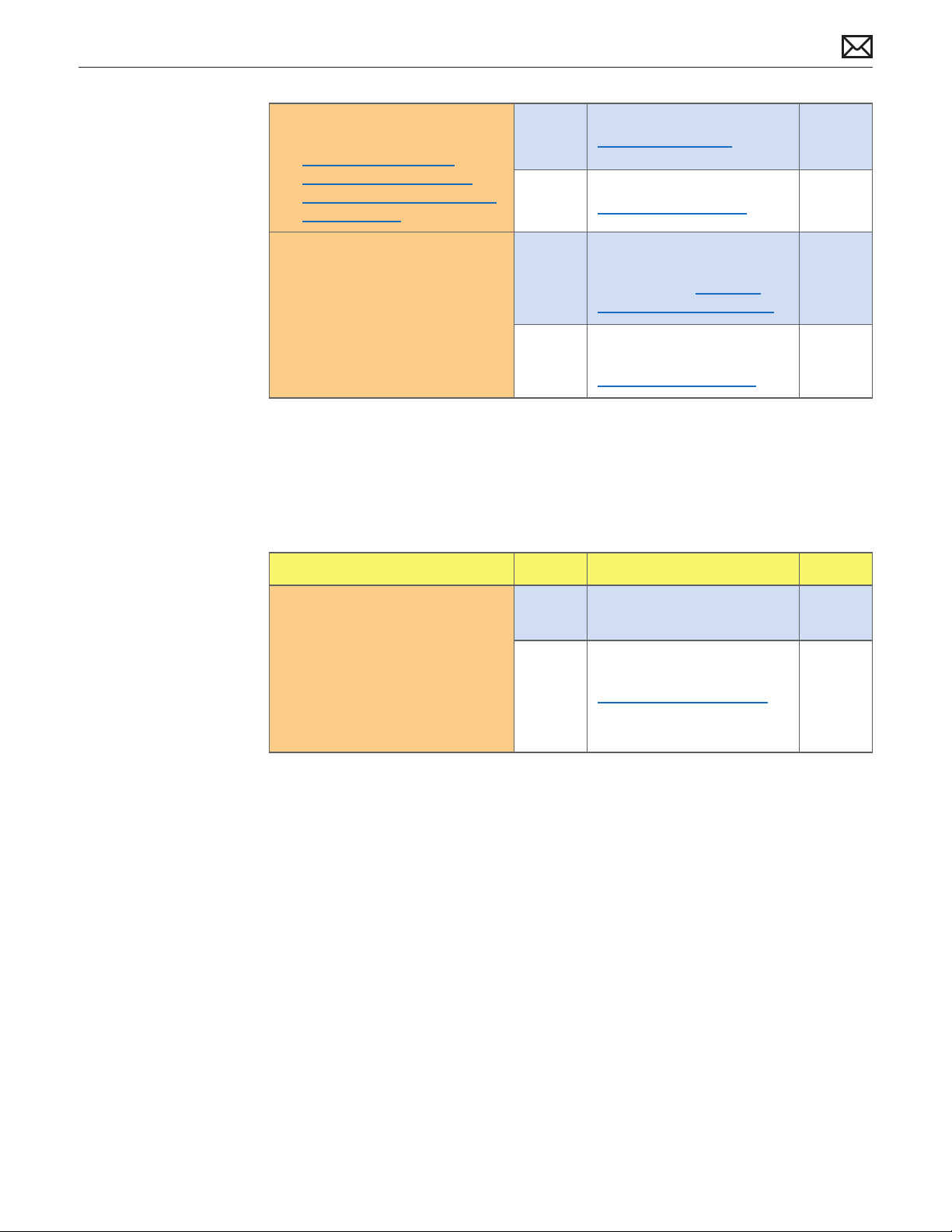
Updated 8 February 2010
Troubleshooting: General: Test Points Diagram, added TP61•
Troubleshooting: Symptom Charts: “Dead Unit / No Power”:•
Step 5: changed “Yes” Action to lead to Blank/No Video, • Step 3;
Step 8, corrected voltage for TP11 to 24.5VDC (was incorrectly noted as 15VDC); •
Step 9, corrected “TP11” to “TP13”.•
Troubleshooting: Symptom Charts: “Camera Issues”: added link to • kBase #HT3957: “About
the LED Cinema Display iSight Camera Firmware Update 1.0”.
Updated 28 October 2009
Added new section: About This Manual•
Basics: replaced Technical Specications (p. 9) with a link to AppleCare Tech Specs•
Troubleshooting: General: updated Troubleshooting Theory section•
Troubleshooting: Symptom Charts: corrected hyperlink at top of p. 17•
Take Apart: General: replaced ESD section with hyperlinks to current ESD articles & training; •
added section for handling and removing a broken glass panel
Take Apart: Stand: added image showing removal of rear housing from stand; added note •
about VESA Mount procedure
Added new sections: Additional Procedures: VESA Mount and Retrieving Mechanism•
Updated 2 December 2008
Feedback
We want your feedback to help improve this and future Technician Guides!
Please email any comments to: smfeedback6@apple.com
2010-02-08
LED Cinema Display (24-inch) — Updates 7
Page 8

Apple Technician Guide
Basics
LED Cinema Display (24-inch)
© 2010 Apple Inc. All rights reserved.
Page 9
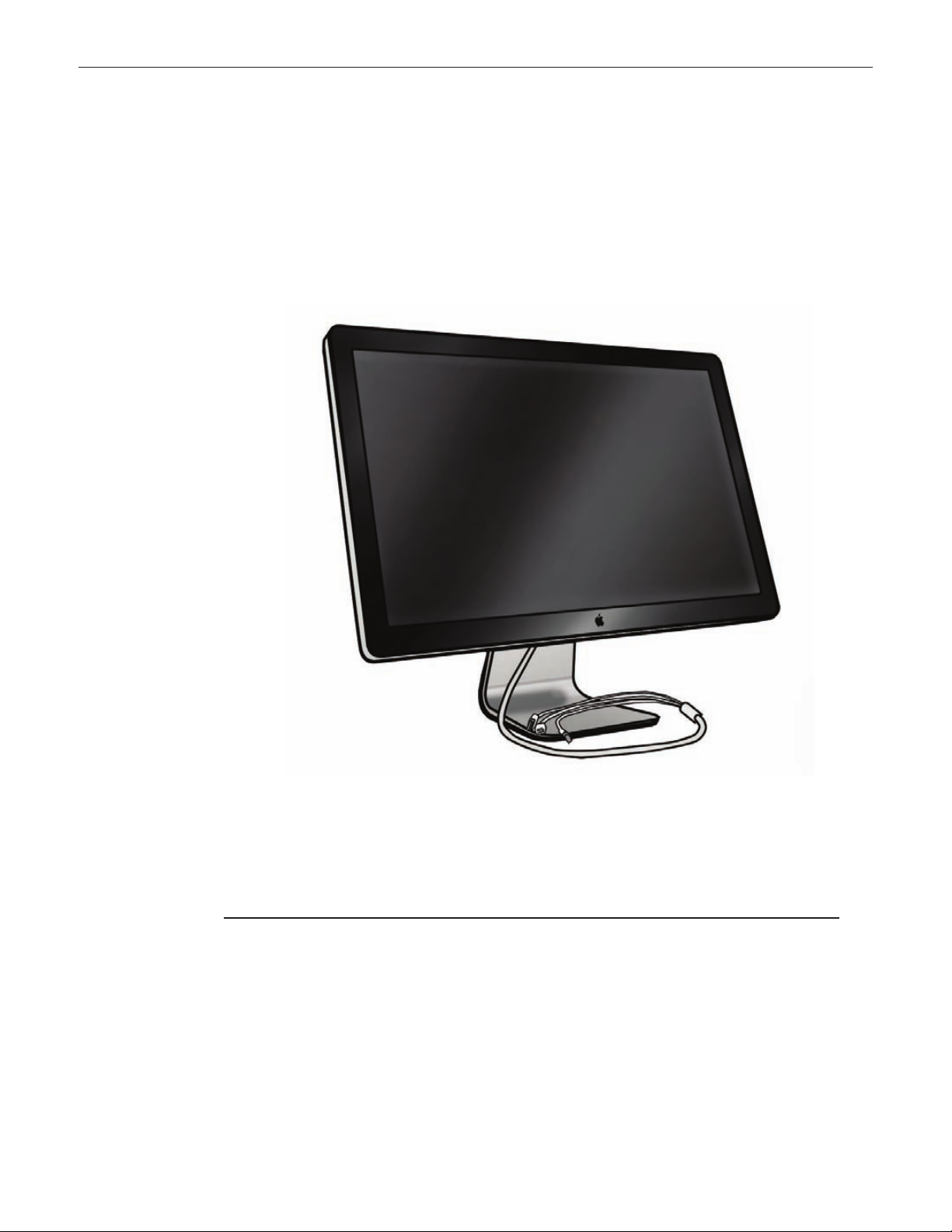
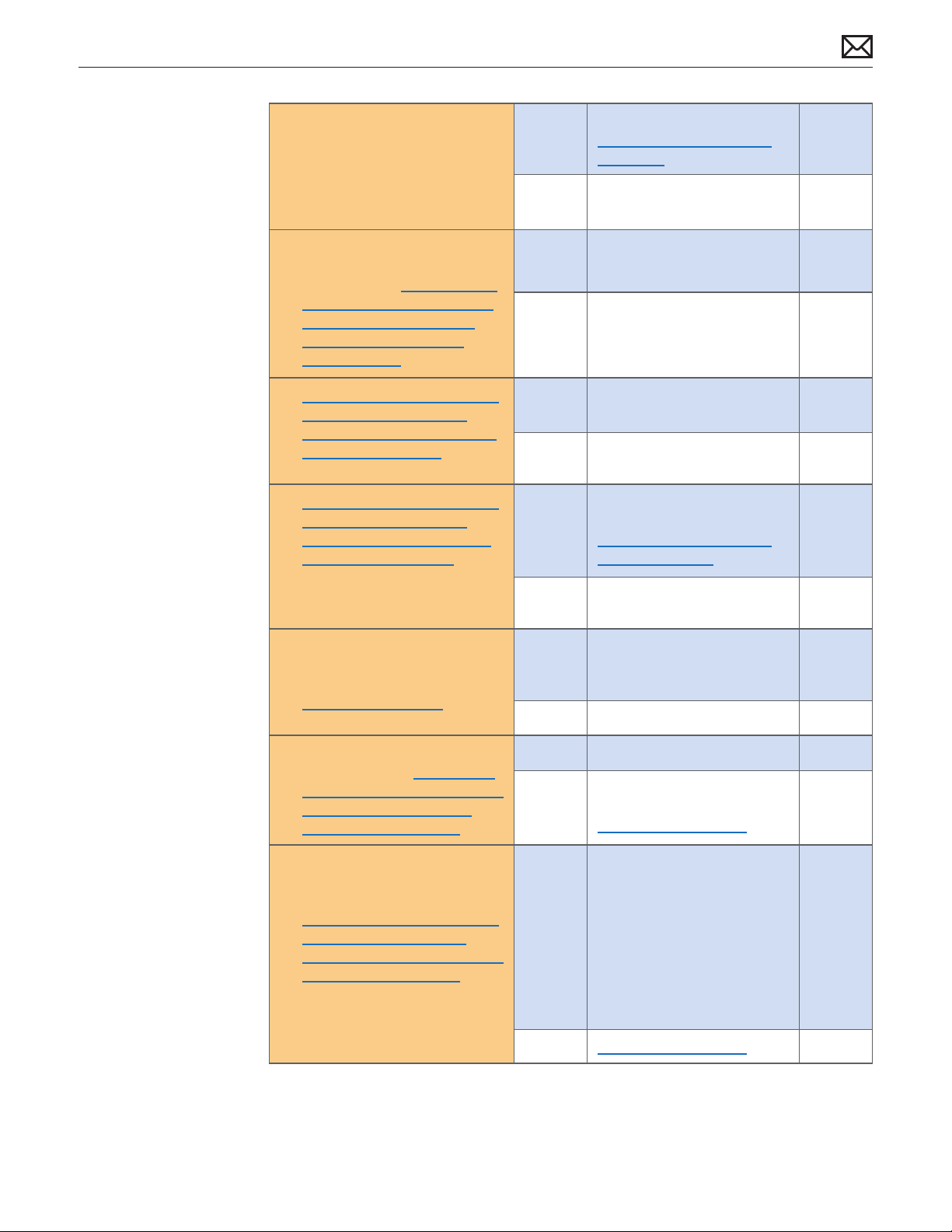
Overview
Identifying Features
The LED Cinema Display (24-inch) is an active-matrix LCD with LED backlight that includes a
built-in iSight camera, a 2.1 speaker system, and a microphone. The native resolution is 1920 x
1200 pixels. The all-in-one cable creates a docking station for portable computers, providing a
MagSafe power connection, Mini DisplayPort video connection, and a 3-port USB hub.
The unit has no buttons. Power is controlled by the state of the connected computer. It is
OFF if it detects the DisplayPort source is powered o. It is in Sleep if it detects the DisplayPort
source is powered but does not send a video signal (i.e., Display Sleep). It is ON when the
DisplayPort source sends a valid video signal. Brightness and speaker volume are controlled via
System Preferences in the Mac OS.
System Requirements
The LED Cinema Display (24-inch) works with Mac computers running Mac OS X 10.5 or later
that have a high-performance Mini DisplayPort.
Product Congurations
For product congurations, refer to AppleCare Tech Specs: http://support.apple.com/specs/
2010-02-08
LED Cinema Display (24-inch) Basics — Overview 9
Page 10
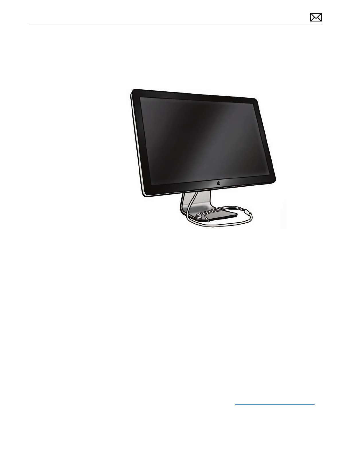
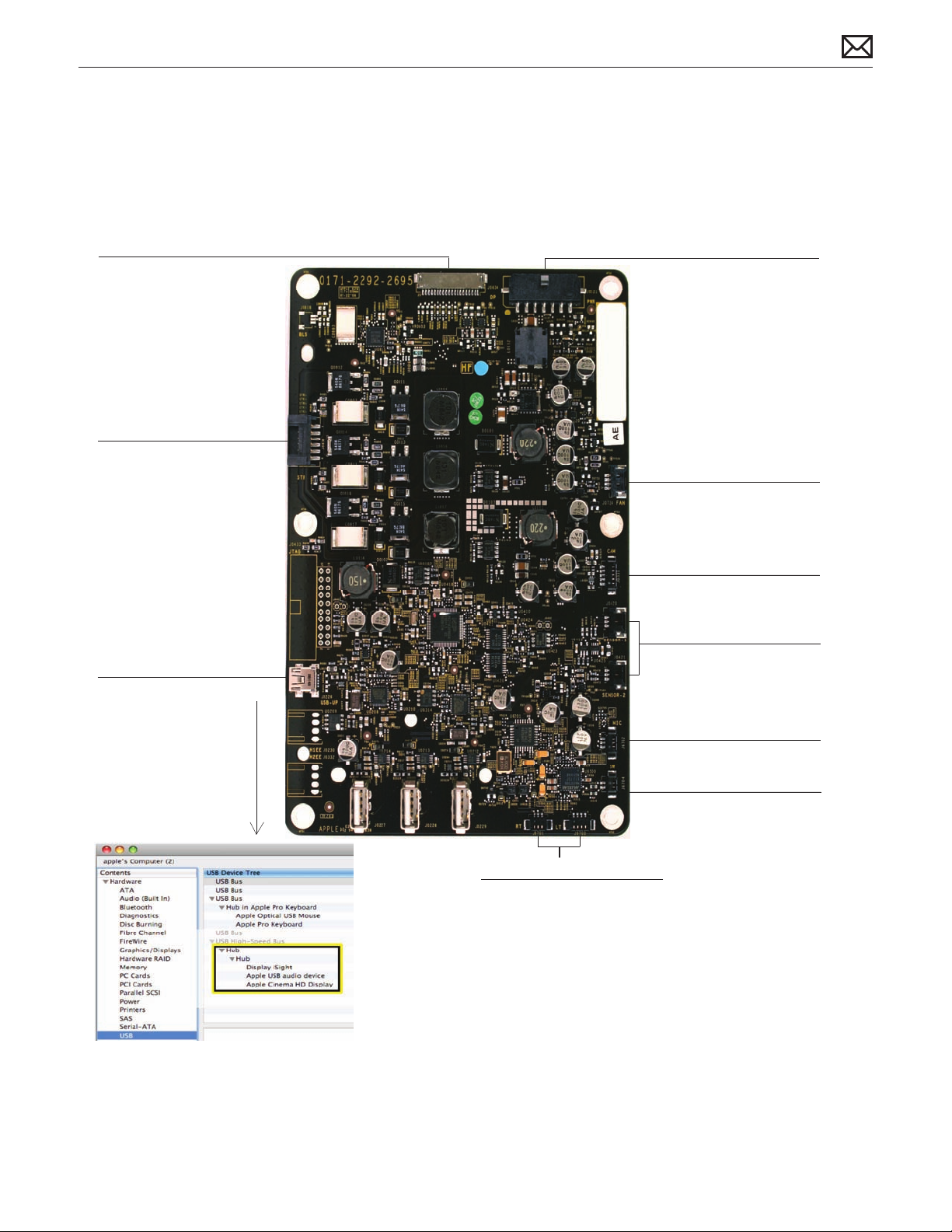
Rear View
The stand is removable in
order to allow the use of a
VESA mount.
Ports
The 3-port USB 2.0 hub
can power three ports at
1.1A each, or up to two
ports at 1.5A each.
All-In-One Cable
Includes (left to right):
USB, Mini DisplayPort, and
MagSafe power.
2010-02-08
LED Cinema Display (24-inch) Basics — Overview 10
Page 11
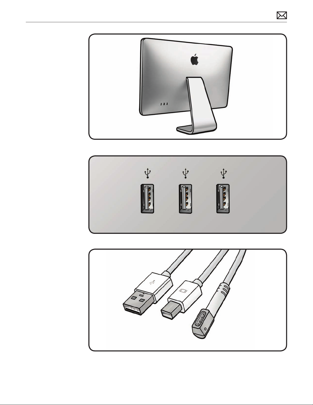
Serial Number Location
Serial Number on Stand
The LED Cinema Display (24-inch)’s serial number is located on the base of the stand. When
replacing a stand, transfer the serial number to the new stand.
Serial Number on Mechanism
The LED Cinema Display (24-inch)’s serial number is also located on the hinge mechanism
inside, for users who remove the stand to use a VESA mount. When replacing a mechanism,
transfer the serial number label to the new mechanism.
2010-02-08
LED Cinema Display (24-inch) Basics — Serial Number Location 11
Page 12

Apple Technician Guide
Troubleshooting
LED Cinema Display (24-inch)
© 2010 Apple Inc. All rights reserved.
Page 13

General Troubleshooting
Troubleshooting Theory
For general information on troubleshooting theory, go to GSX and nd the Service Training
course menu link. From there you can access the Troubleshooting Theory self-paced course.
Hardware vs. Software
For information on how to isolate a hardware issue from a software issue, refer to:
kBase #TS1388: Isolating issues in Mac OS X
For information on how to troubleshoot a software issue, refer to:
kBase #HT1199: Mac OS X: How to troubleshoot a software issue
2010-02-08
LED Cinema Display (24-inch) Troubleshooting — General Troubleshooting 13
Page 14
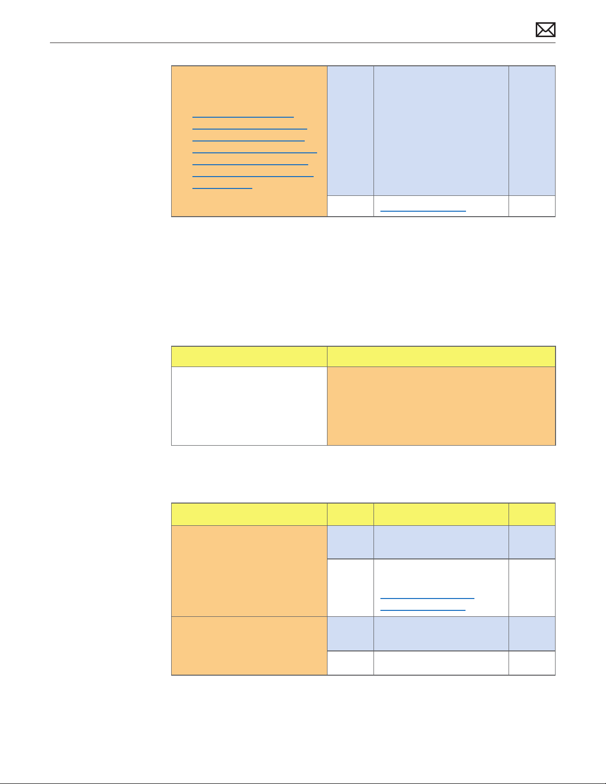
Functional Overview
LCD Function Interface
• No power to LCD
• No LED backlight
DC In
• No power
Camera
• Not detected in USB Device Tree
• No green camera LED
• No camera video
Fan (1) & LCD (2) Temp Sensors
• Fan runs fast if sensor is:
° disconnected
° connected to wrong location on MLB
° not properly mounted or located
° faulty
Microphone
• Not detected in Sound Pref pane
• No, low, distorted audio input
Subwoofer
• No, low, distorted bass
Right & Left Speakers
• Not detected in Sound Pref pane
• No, low, distorted channel(s)
Blower (Fan)
• No rotation leading to overtemp condition
• Excessive noise/vibration due to faulty fan
* Also see Fan (1) & LCD (2) Temp Sensors
symptoms below.
LED Driver (Backlight)
• No LED backlight
• Dim or low brightness
Upstream USB
• Not detected in USB Device Tree or
System Preference panes
° iSight camera
° Sound output
° Microphone input
° LED calibration &
brightness control
° 3 x USB ports
A guide to possible symptoms as they relate to ports on the main logic board:
2010-02-08
LED Cinema Display (24-inch) Troubleshooting — General Troubleshooting 14
Page 15
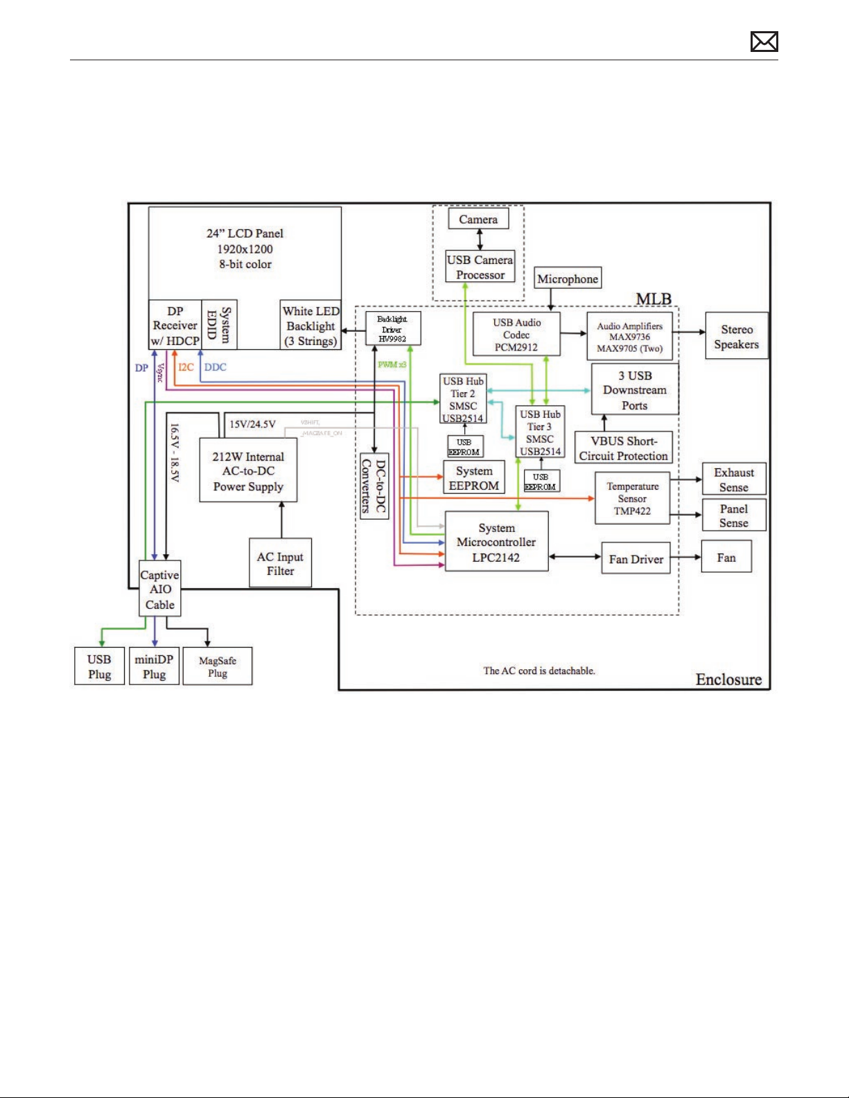
Block Diagram
Refer to this diagram to see how modules are interrelated:
2010-02-08
LED Cinema Display (24-inch) Troubleshooting — General Troubleshooting 15
Page 16
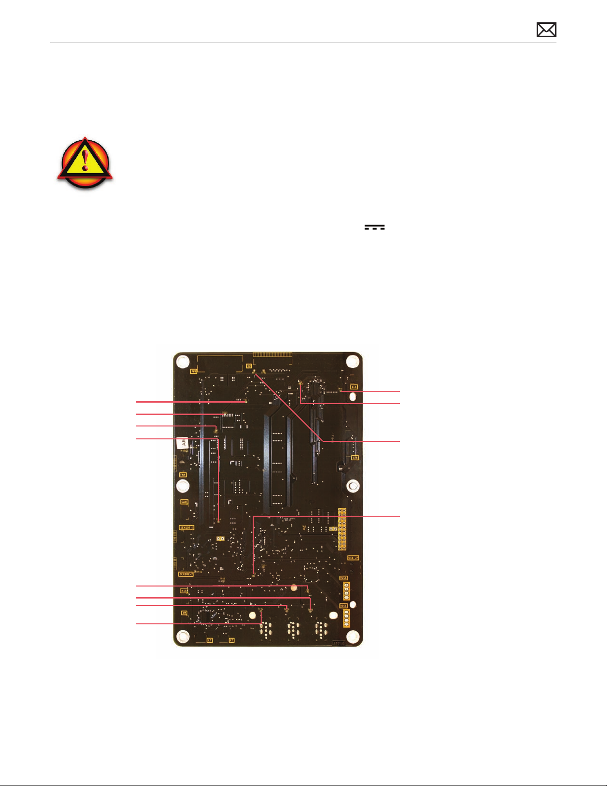
Test Points Diagram
Below are main logic board test points that you can use
to verify proper power flow in LED Cinema Display (24-inch).
All voltages assume that the display is plugged into
a power outlet, and NOT into the host computer (unless
otherwise noted).
• Turn the dial of your voltmeter/multimeter to measure
DC (direct current) . If your voltmeter requires that
you set a voltage range, choose a DC range that includes
the voltage that you are measuring.
• Connect the black probe to ground by gently inserting into
any of the LCD screw posts closest to the logic board.
Keep in mind that the threading in the screw posts is fragile
and can be easily destroyed.
• Touch the red probe to appropriate test point.
• Verify voltage.
DC In
TP 11: 24.5 VDC
TP 12: 24.5 VDC
TP 13: 12.0 VDC
*TP 14: 5.0 VDC
*only if USB plugged into host
USB Hub 1 for 3 ports
*TP 21: 3.3 VDC
*TP 22: 5.2 VDC
*TP 23: 5.2 VDC
*TP 24: 5.2 VDC
*only if USB plugged into host
USB Hub 2 for camera & audio
*TP 31: 3.3 VDC
*only if USB plugged into host
LED Backlight Driver
TP 81: 24.5 VDC
TP 82: 1.0 VDC
TP 61: 3.3 VDC
Warning:
HIGH VOLTAGE: Use extreme caution
when live testing.
• Never touch the power supply.
• Do NOT lean over or accidentally touch
power supply area during live testing.
• Keep your fingers behind the finger
guards on the test probes when making
measurements on main logic board!
Refer to this diagram to see the location of test points and instructions for their use:
2010-02-08
LED Cinema Display (24-inch) Troubleshooting — General Troubleshooting 16
Page 17
Symptom Charts
Follow steps in the order indicated below. If an action resolves the issue, retest system to verify.
Note: A compilation of Quick Check tables is available at:
http://service.info.apple.com/QRS/en/quickreference.pdf
Startup and Power Issues
Dead Unit / No Power
Unlikely cause: LCD panel, blower, subwoofer, speakers, camera, microphone
Quick Check
Symptoms Quick Check
Dead Unit / No Power
No power•
No image•
No fan spin•
Non-operational•
Verify power source.1.
Verify USB/display/power connectors are fully 2.
seated.
Verify display is used with supported system.3.
Use with known-good system. 4.
If used as second display, check display
preferences to see if display is recognized.
Check brightness setting.5.
Deep Dive
Check Result Action Code
Verify display’s USB hub and 1.
built-in camera are listed in the
System Proler’s USB device
tree.
Yes
No Go to step 2.
Power supply OK. Go to
Blank/No Video symptom
code ow.
2010-02-08
LED Cinema Display (24-inch) Symptom Charts — Startup and Power Issues 17
Page 18
Unplug and replug the Mini 2.
DisplayPort connector into a
supported system and monitor
the portable’s display. Verify
that the portable’s display
briey turns o then back on.
Yes Logic board OK. Go to
Blank/No Video symptom
code ow.
No Go to step 3.
Remove LCD panel and 3.
disconnect LCD function
interface cable. Verify voltage
on logic board between test
point TP11 (24.5VDC) and
chassis ground (GND) is
23.3–25.7 VDC.
Verify voltage on logic board 4.
between test point TP61
(3.3VDC) and chassis ground
(GND) is 3.1–3.5 VDC.
Verify voltage on logic board 5.
between test point TP13
(12VDC) and chassis ground
(GND) is 11.4–12.6 VDC.
Ve6. rify all connections between
power supply, all-in-one cable,
and logic board are secure. See
Functional Overview.
Yes 24.5VDC from power supply
OK. Go to step 4.
No No power or incorrect power
at logic board.
Go to step 6.
Yes 3.3VDC power on logic board
OK. Go to step 5.
No No power at logic board.
Go to step 9.
Yes All DC voltages present on
logic board; power OK. Go to
Blank/No Video symptom
code ow, Step 3.
No No power at logic board.
Go to step 9.
Yes If connections are secure and
display still does not function
correctly, go to step 8.
No Reseat connectors and retest.
2010-02-08
Disconnect power supply cable 7.
from logic board. Verify cable
voltage at connector between
Pin 1 and chassis ground
(GND) is 14.3–15.8 VDC.
Disconnect all connectors from 8.
the logic board EXCEPT the
power supply cable.
Verify voltage on logic board
between test point TP11
(24.5VDC) and chassis ground
(GND) is 23.3-25.7 VDC.
LED Cinema Display (24-inch) Symptom Charts — Startup and Power Issues 18
Yes Go to step 8.
No
No power or incorrect power
to logic board.
Replace power supply.
Yes Power supply OK. Suspect
possible short, damaged
connector, or faulty sensor/
fan/speaker. Reconnect
connectors one at a time and
retest for 24.5VDC at TP11.
Replace aected part that
causes the 24.5VDC voltage to
disappear.
No
Replace power supply. P01
P01
L14
Page 19
Disconnect all connectors from 9.
the logic board EXCEPT the
power supply cable.
Verify voltages on logic
board between test points
TP61 (3.3VDC) and chassis
ground (GND) is 3.1–3.5 VDC,
and between TP13 (12VDC)
and chassis ground (GND) is
11.4–12.6 VDC.
Yes Power supply OK. Suspect
possible short, damaged
connector, or faulty sensor/
fan/speaker. Reconnect
connectors one at a time
and retest for 3.3VDC at TP61
and 12VDC at TP13. Replace
aected part that causes the
3.3VDC or 12VDC voltages to
disappear.
L14
No
Replace logic board. L01
Burnt Smell/Odor
Unlikely cause: LCD panel, blower, subwoofer, speakers, camera, microphone
Quick Check
Symptoms Quick Check
Burnt Smell/Odor
No power•
No image•
No fan spin•
Non-operational•
Deep Dive
Verify source of smell/odor is emanating from the 1.
display.
Verify display is functional.2.
Remove air vent obstructions.3.
2010-02-08
Check Result Action Code
Verify by visual inspection of 1.
each module the location the
source of burnt smell/odor
Verify no other modules or 2.
internal cables are aected or
the root cause.
LED Cinema Display (24-inch) Symptom Charts — Startup and Power Issues 19
Yes Located aected module.
Go to step 2.
No
Yes Replace all aected module(s)
No Return unit to user.
Not able to locate aected
module. Go to
Dead Unit / No Power
symptom code ow.
and/or cable(s).
P08
Page 20
MagSafe Adapter – No Power
Unlikely cause: LCD panel, logic board, blower, subwoofer, speakers, camera, microphone
Quick Check
Symptoms Quick Check
MagSafe Adapter – No Power
No power to MagSafe •
connector
MagSafe connector status LED •
does not illuminate
No power to portable •
computer without battery
Verify power source. 1.
Verify display is operating.2.
Ensure MagSafe connector and receptacle are 3.
clean.
Verify LED glowing amber or green when 4.
MagSafe connector attached to compatible
portable computer.
Deep Dive
Check Result Action Code
Attach MagSafe cable to 1.
known-good compatible
system. Verify connector status
LED illuminates amber or
green.
Visually inspect MagSafe cable 2.
and user’s portable MagSafe
receptacle for physical damage,
stuck pins, debris, or metal
fragments.
Yes LED color illuminates amber
or green depending on
charging state. Go to step 4.
No Go to step 2.
Yes
No Go to step 3.
See kBase #HT2315.
Go to step 4.
2010-02-08
Verify after unplugging and 3.
replugging the display’s AC
power cord, the MagSafe
connector LED color illuminates
amber or green depending
charging state.
Verify a known-good 4.
compatible system operates,
and charges a discharged
battery to 100% simultaneously
from MagSafe cable.
LED Cinema Display (24-inch) Symptom Charts — Startup and Power Issues 20
Yes Go to step 4.
No
Yes Repair complete.
No
Replace all-in-one cable. P15
Replace power supply.
If needed afterwards, refer
to Dead Unit/No Power
symptom code ow.
P01
Page 21
Sleep/Wake Issue
Unlikely cause: LCD panel, blower, subwoofer, speakers, camera, microphone
Quick Check
Symptoms Quick Check
Sleep/Wake Issue
Won’t go to sleep or wake up •
from sleep
Verify display is being used with supported 1.
system.
Use with known-good system. If used as second 2.
display, check display preferences to see if display
is recognized by system.
Verify USB/display/power connectors are fully 3.
seated.
Check brightness setting.4.
Deep Dive
Check Result Action Code
Verify display’s USB hub and 1.
built-in camera are listed in the
System Proler’s USB device
tree.
Verify voltage on logic 2.
board between J0121 Pin 1
(24.5VDC) and Pin 3 (GND) is
23.3–25.7 VDC.
Yes Power supply OK.
Go to step 3.
No Go to step 2.
Yes Power supply OK.
Go to step 3.
No No power at logic board.
Go to step 4.
2010-02-08
Unplug and replug the Mini 3.
DisplayPort connector into
a supported powered-up
portable system and monitor
the portable’s display. Verify
that the portable’s display
briey turns o then back on.
Verify all connections between 4.
power supply, all-in-one cable,
and logic board are secure. See
Functional Overview.
LED Cinema Display (24-inch) Symptom Charts — Startup and Power Issues 21
Yes Logic board OK.
Go to step 6.
No Go to step 4.
Yes If connections are secure and
display still does not function
correctly, go to step 5.
No Reseat connectors and retest.
Page 22
Disconnect DC power cable 5.
from J0121 on logic board.
Verify cable voltage at
connector between Pin 1
(24.5VDC) and Pin 3 (GND) is
23.3–25.7 VDC.
Yes Power to logic board.
Replace logic board.
No
No power to logic board.
Replace power supply.
M01
P01
Verify all connections between 6.
logic board and LCD are secure.
Visually inspect cables and
connectors for any debris,
damage, or bent pins.
Yes
No
If connections are secure and
display still does not function
correctly, go to Blank/No
Video symptom code ow.
Reseat connectors and retest.
For damaged AIO cable,
replace all-in-one cable.
Uncategorized Symptoms
Deep Dive
Check Result Action Code
Verify whether existing 1.
symptom code applies to the
issue reported by the user.
Yes Jump to appropriate
symptom code ow.
No
Document reported failure
and send feedback to
smfeedback6@apple.com
stating that a suitable
symptom code wasn’t found.
X04
N99
2010-02-08
LED Cinema Display (24-inch) Symptom Charts — Startup and Power Issues 22
Page 23
Display Issues
Blank / No Video, No Backlight
Unlikely cause: power supply, blower, subwoofer, speakers, camera, microphone
Quick Check
Symptoms Quick Check
Blank / No Video, No Backlight
No video•
No backlight•
Dim backlight•
Verify display being used with supported system.1.
Verify USB/display/power connectors are fully 2.
seated.
Use with known-good system. If used as second 3.
display, check display preferences to see if display
is recognized by system.
Check brightness setting.4.
Deep Dive
Check Result Action Code
Verify display’s USB hub and 1.
built-in camera are listed in the
System Proler’s USB device
tree.
Unplug and replug the Mini 2.
DisplayPort connector into
a known-good, supported,
powered-up portable system
and monitor the portable’s
display. Verify that the
portable’s display briey turns
o then back on.
Yes Power supply and USB
communication OK.
Go to step 3.
No Go to step 2.
Yes Display detected by system.
Go to step 3.
No
Go to Dead Unit/No Power
symptom code ow.
2010-02-08
Darken room and connect to a 3.
known-good supported system.
Verify backlight by looking for
faint glow from display.
LED Cinema Display (24-inch) Symptom Charts — Display Issues 23
Yes Video signal from host system
OK. Backlight ON.
Go to step 5.
No Go to step 4.
Page 24
Verify that the LCD function 4.
interface cable and LED driver
cable connections are secure.
See Functional Overview.
Yes If connections are OK and
secure and the display is still
blank, go to step 5.
No
If cable is damaged,
replace all-in-one cable or
replace function cable.
L14
Shine bright (low heat) 5.
ashlight into the front of the
LCD. Verify if an image is being
displayed.
Verify voltage on logic board 6.
between test point TP81
(24.5VDC) and chassis ground
(GND) is 23.3–25.7 VDC.
Yes Image present but backlight
is not ON. Go to step 6.
No
Yes LED backlight power present.
No
Replace LCD panel. L03
Replace LCD panel.
Poor or no LED backlight
power at logic board.
Replace logic board.
Noise / Unstable Flicker
Unlikely cause: blower, subwoofer, speakers, camera, microphone
Quick Check
Symptom Quick Check
Noise / Unstable Flicker
Image icker•
Audible noise•
Verify display being used with supported system.1.
Verify USB/display/power connectors are fully 2.
seated.
L03
L07
2010-02-08
Use with known-good system. If used as second 3.
display, check display preferences to see if display
is recognized by system.
Verify known-good source sound le not causing 4.
speaker distortion.
Deep Dive
Check Result Action Code
Verify if issue is due to video 1.
ickering coming from display.
LED Cinema Display (24-inch) Symptom Charts — Display Issues 24
Yes Suspected ickering issue.
Go to step 2.
No Audible noise issue.
Go to step 8
Page 25
Verify display’s USB hub and 2.
built-in camera are listed
in the System Proler’s USB
device tree is not disappearing
intermittently (refresh System
Proler to observe).
Yes Power supply OK.
Go to step 3.
No
Go to Dead Unit/No Power
symptom code ow.
Unplug and replug the 3.
Mini DisplayPort and USB
connectors into a supported
powered-up portable system
and monitor the portable’s
display. Verify that the
portable’s display briey turns
o then back on.
Verify all connections between 4.
power supply, all-in-one cable,
LCD, and logic board are secure.
See Functional Overview.
Disconnect all-in-one cable 5.
and LCD function interface
cable from logic board and
system. Verify connectors and
cable under magnication for
pinched cables and damaged/
bent pins.
Disconnect LED driver cable 6.
from logic board. Verify
connectors and cable under
magnication for pinched cable
and damaged or bent pins.
Yes If connections are secure and
display still shows unstable
ickering, go to step 4.
No Reseat connectors and retest.
Yes If connections are secure and
the display is still unstable
ickering, go to step 5.
No Reseat connectors and retest.
Yes
If cable is damaged,
replace all-in-one cable or
replace LCD function
interface cable.
No Go to step 6.
Yes
Damaged LED driver cable.
Replace LCD panel.
No Go to step 7.
L14
L14
2010-02-08
Shine bright (low heat) 7.
ashlight into the front of the
LCD. Verify if an image is being
displayed during ickering.
Verify the source of the noise 8.
is the electrical as opposed to
mechanical
LED Cinema Display (24-inch) Symptom Charts — Display Issues 25
Yes
Image present but backlight
is ickering.
Replace logic board.
No
Replace LCD panel. L06
Yes Noises that are not audible
from the normal user position
are considered acceptable.
No
Noise from another source.
Go to Noise, Hum, Vibration
symptom code ow.
L06
Page 26
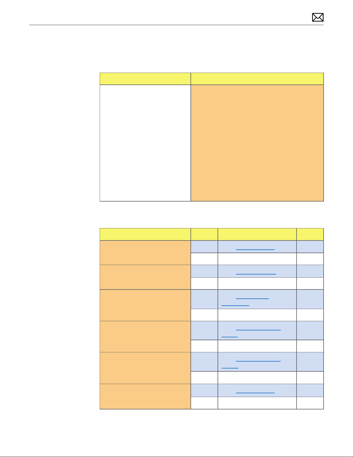
LCD Image Issues
Quick Check
Symptom Quick Check
LCD Issues
Pixel anomalies•
Non-uniform brightness•
Incorrect/missing colors•
Distorted/blurred image•
Vertical/horizontal lines•
Allow display to reach normal operating 1.
temperature for about 15 minutes before
evaluating front-of-screen performance.
Verify display being used with supported 2.
system. If used as second display, check display
preferences to see if display is recognized by
system.
Verify USB/display/power connectors are fully 3.
seated.
Check display preferences for use of custom 4.
display prole.
Check brightness setting.5.
Clean glass panel while checking for dust/debris.6.
Deep Dive: General
Check Result Action Code
Verify if issue is blank/no video.1. Yes
Go to blank/no video.
2010-02-08
Verify if issue is bright or dark 2.
dot pixel anomalies.
Verify if issue is non-uniform 3.
brightness.
Verify if issue is incorrect/4.
missing colors.
Verify if issue is distorted/5.
blurred image.
Verify if issue is vertical or 6.
horizontal lines.
No Go to step 2.
Yes
No Go to step 3.
Yes
No Go to step 4.
Yes
No Go to step 5.
Yes
No Go to step 6.
Yes
No LCD functioning OK.
LED Cinema Display (24-inch) Symptom Charts — Display Issues 26
Go to pixel anomalies.
Go to non-uniform
brightness.
Go to incorrect/missing
colors.
Go to distorted/blurred
image.
Go to vert/horiz lines.
Page 27
Deep Dive: Pixel Anomalies
Unlikely cause: logic board, power supply, blower, subwoofer, speakers, camera, microphone
Check Result Action Code
Determine if “defects” are dust/1.
debris on surface of glass panel
or LCD panel.
Determine if bright pixel 2.
defects exceed the acceptable
number. See kBase #HT1721
Determine if dark pixel defects 3.
exceed the acceptable
number. See kBase #HT1721
Determine if the combination 4.
of bright/dark pixel defects
exceed the acceptable
number. See kBase #HT1721
Yes
No Go to step 2.
Yes Replace LCD panel. L08
No LCD meets bright pixel defect
Yes Replace LCD panel. L08
No LCD meets dark pixel defect
Yes Replace LCD panel. L08
No Explain to user that LCD is
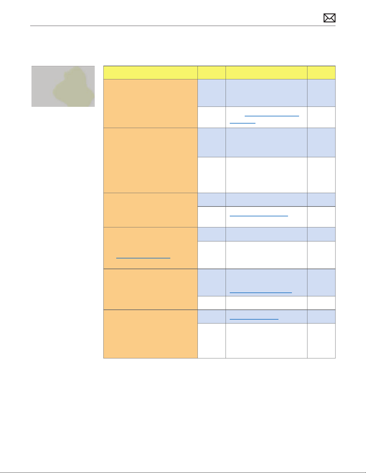
Deep Dive: Non-Uniform Brightness
Clean glass/LCD panel.
Note: If debris is inside LCD, it
can’t be cleaned, therefore
replace LCD panel.
specications. Go to step 3.
specications. Go to step 3.
within specications for pixel
defects. Do not replace LCD.
Unlikely cause: logic board, power supply, blower, subwoofer, speakers, camera, microphone
Check Result Action Code
Determine if brightness 1.
uniformity issue is visible after
display has warmed up for
approximately 15 minutes.
Display user-provided 2.
examples showing brightness
uniformity issue. Determine if
issue appears excessive when
compared to a similar unit.
Remove front bezel and 3.
loosen screws securing LCD.
Determine if brightness
uniformity improves.
Yes Go to step 2.
No Display backlight can take
several minutes to stabilize.
Yes Go to step 3.
No Explain to user that
LCD appears to meet
specications.
Yes Inspect for mechanical
interference with screws/
chassis/wires making contact
with back of LCD. Retest
No
Replace LCD panel. L07
2010-02-08
LED Cinema Display (24-inch) Symptom Charts — Display Issues 27
Page 28
Deep Dive: Incorrect/Missing Colors
Unlikely cause: power supply, blower, subwoofer, speakers, camera, microphone
Check Result Action Code
Verify display’s USB hub and 1.
built-in camera are listed in the
System Proler’s USB device
tree.
Verify System Preferences: 2.
Displays: Color is using a valid
display prole for this display.
Verify that the glass panel and 3.
LCD are free of contaminants.
Verify all connections between, 4.
all-in-one cable, LCD, and
logic board are secure. See
Functional Overview.
Yes Power supply and USB
communication OK.
Go to step 2.
No
Yes If display prole is valid and
No Calibrate display by creating a
Yes Go to step 4.
No
Yes Go to step 5.
No Reseat connections, replace
Go to USB Issues symptom
code ow.
the colors are still incorrect or
missing, go to step 3.
manual prole using calibrate
feature in System Preferences:
Displays: Color. Retest.
Clean glass/LCD panel.
Retest.
damaged cable(s) as needed.
Retest.
2010-02-08
Set desktop pattern in System 5.
Preferences to “solid gray light.”
Verify if incorrect/missing color
issue aects entire display.
Set up user’s display side-by-6.
side with a known-good display
showing the same image. Verify
if issue is noticeably worse on
the display being tested.
LED Cinema Display (24-inch) Symptom Charts — Display Issues 28
Yes
No Go to step 6.
Yes
No Small variations in color
Suspect poor video
connection.
Replace all-in-one cable.
Replace LCD panel. L02
uniformity are normal and do
not warrant replacement or
repair of the display.
L14
Page 29

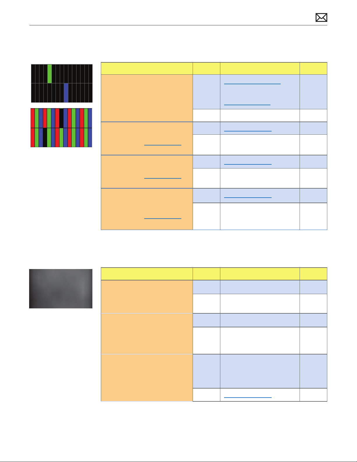
Deep Dive: Distorted/Blurred Image
Unlikely cause: power supply, blower, subwoofer, speakers, camera, microphone
Check Result Action Code
Verify display’s Mini DisplayPort 1.
connector is plugged into
known-good system.
Reseat Mini DisplayPort cable at 2.
system and display logic board.
Determine if image corruption
issue was resolved.
Disconnect Mini DisplayPort 3.
cable from system and display
logic board. Inspect connectors
and cable under magnication
for pinched cables and
damaged/bent pins.
Yes Go to step 2.
No Connect Mini DisplayPort
cable to known-good system.
Yes Loose cable. Issue resolved.
No Go to step 3.
Yes
No
Replace all-in-one cable. X04
Replace LCD panel. L04
Deep Dive: Vertical/Horizontal Lines
Unlikely cause: logic board, power supply, blower, subwoofer, speakers, camera, microphone
Check Result Action Code
Verify display’s USB hub and 1.
built-in camera are listed in the
System Proler’s USB device
tree.
Unplug and replug the Mini 2.
DisplayPort connector into
a supported powered-up
portable system and monitor
the portable’s display. Verify
that the portable’s display
briey turns o then back on.
Verify all-in-one cable, and all 3.
connections between logic
board and LCD are secure.
Visually inspect cables and
connectors for any debris,
damage, or bent pins.
Yes Power supply and USB
communication OK.
Go to step 3.
No Go to step 2.
Yes Logic board OK.
Go to step 3.
No Go to step 3.
Yes
No
If connections are secure
and the display still does not
function correctly,
replace LCD panel.
Connector/cable damage.
Go to Mechanical Physical
Damages symptom code
ow.
L05
2010-02-08
LED Cinema Display (24-inch) Symptom Charts — Display Issues 29
Page 30

Physical Damage
Quick Check
Symptom Quick Check
Physical Damage
Cracked LCD•
Scratched LCD polarizer•
Scorched or melted LCD•
LCD impact damage•
Determine damage caused by user/technician 1.
environment, accidental damage, or abuse.
Inform user/technician the failures are not 2.
covered by Apple warranties. Refer to
http://www.apple.com/legal/warranty
Uncategorized Symptoms
Deep Dive
Check Result Action Code
Verify whether existing 1.
symptom code applies to the
issue reported by the user.
Yes Jump to appropriate
symptom code ow.
No
Document reported failure
and send feedback to
smfeedback6@apple.com
stating that a suitable
symptom code wasn’t found.
L99
2010-02-08
LED Cinema Display (24-inch) Symptom Charts — Display Issues 30
Page 31

Input/Output Issues
USB Issues
Unlikely cause: LCD panel, blower, subwoofer, speakers
Quick Check
Symptoms Quick Check
USB Issues
External USB device(s) not •
recognized
Wired USB keyboard/mouse •
not recognized
Verify display’s USB and Mini DisplayPort 1.
connectors are plugged into known-good
supported system.
Launch System Proler and conrm that display’s 2.
USB hub is visible.
Deep Dive
Check Result Action Code
Verify display’s USB and Mini 1.
DisplayPort connectors are
plugged into known-good
system.
Verify USB uplink cable 2.
connection to logic board
is secure. See Functional
Overview.
Disconnect USB cable from 3.
logic board and system. Inspect
connectors and cable under
magnication for pinched
cables and damaged/bent pins.
Yes Go to step 2.
No Connect display’s USB and
Mini DisplayPort cables.
Yes If connections are secure and
USB ports still do not function
correctly, go to step 3.
No Reseat connector and retest.
Yes
No Replace logic board. X04
Replace all-in-one cable. M15
2010-02-08
Verify USB device and cable 4.
function properly on a known
good system.
Inspect all three USB ports on 5.
display under magnication for
damaged/bent pins.
LED Cinema Display (24-inch) Symptom Charts — Input/Output Issues 31
Yes Go to step 7
No Go to step 6.
Yes USB ports damaged.
Go to step 7.
No Verify USB peripheral works
on known-good display.
Page 32

Verify that USB device is 6.
supported with the system and
Mac OS X version being used.
Yes Go to step 7.
No Refer to device manufacturer
for compatibility support.
Verify that USB device works 7.
with another known good
display.
Yes
No Refer to device manufacturer
Replace logic board. M15
for compatibility support.
Camera Issues
Unlikely cause: LCD panel, power supply, blower, subwoofer, speakers, microphone
Quick Check
Symptoms Quick Check
Camera Issues
Camera not detected•
No green LED for camera•
Excessive blooming•
Poor white balance•
Poor focus•
Image distortion•
Verify display’s USB and Mini DisplayPort 1.
connectors are plugged into known-good
supported system.
Verify that all rmware updates have been 2.
applied. See kBase #HT3957: “About the LED
Cinema Display iSight Camera Firmware
Update 1.0”
Launch System Proler and conrm that display’s 3.
USB hubs are visible.
2010-02-08
Verify camera lens and glass panel are clear of 4.
contaminants.
Deep Dive
Check Result Action Code
Launch System Proler and 1.
conrm that the display’s USB
hub is visible in the USB tree.
Launch System Proler and 2.
conrm that iSight camera is
recognized in display’s USB
tree.
LED Cinema Display (24-inch) Symptom Charts — Input/Output Issues 32
Yes USB hub recognized.
Go to step 2.
No
Yes Go to step 3.
No
Go to USB Issues symptom
code ow.
Reseat camera cable and
retest. If problem persists,
replace camera cable.
L14
Page 33

Launch PhotoBooth. Verify that 3.
green LED near camera lens
turns on.
Yes Go to step 4.
No
Replace camera. Retest. M13
Launch PhotoBooth. Verify that 4.
camera image appears normal.
Yes Repair completed.
No
Clean camera lens. If needed,
replace camera. Retest.
Audio Issues
Unlikely cause: LCD panel, power supply, blower, camera
Quick Check
Symptoms Quick Check
Audio Issues
Internal speakers not •
recognized
No sound•
Garbled sound•
No bass•
No treble•
Microphone not working•
Verify display’s USB and Mini DisplayPort 1.
connectors are plugged into known-good
supported system.
Launch System Preferences and select Sound 2.
output options. Verify that display’s sound output
option is set to display’s internal speakers.
Verify that “output volume” is set above minimum. 3.
(Suggest setting at midpoint.)
Verify that output volume ‘mute’ option is not 4.
checked.
M13
2010-02-08
Deep Dive: Audio Issues, General
Check Result Action Code
Launch System Proler and 1.
conrm that display’s USB hub
is visible.
Determine if user-reported 2.
issue is with display’s internal
microphone.
LED Cinema Display (24-inch) Symptom Charts — Input/Output Issues 33
Yes USB hub circuit OK.
Go to step 2.
No Go to step 3.
Yes
No Go to step 3.
Go to
Audio Issues: Microphone
symptom code ow.
Page 34

Launch System Preferences: 3.
Sound and select ‘sound
output’ options. Verify output
option is set to display’s
internal speakers.
Yes Go to step 6.
No
Set output to internal
speakers. Retest. If needed,
replace logic board.
L11
Disconnect USB uplink cable 4.
from logic board and system.
Inspect cable connectors and
cable under magnication for
pinched cables and damaged
or bent pins.
Disconnect USB uplink cable 5.
from logic board. Inspect logic
board USB connector under
magnication for damaged or
bent pins.
Launch System Preferences 6.
and select Sound Eects
options. Verify that sounds play
normally from left and right
speakers.
Launch System Preferences 7.
and select Sound output
options. Verify sound quality
normal when balance control
set to ‘left only’ and ‘right only’
speakers.
Yes
Replace all-in-one cable. L14
No Go to step 5.
Yes
Replace logic board.
Retest.
No Go to step 6.
Yes Speakers and amplier circuit
are OK.
No Reseat left, right, and
subwoofer speaker
connections on logic board
while inspecting cables
for damage. Retest. If not
resolved, go to step 7.
Yes Speakers and amplier circuit
are OK.
No
Based on results of test,
replace left or right speaker
or replace subwoofer. Retest.
If not resolved, go to step 8.
M15
L11
2010-02-08
Launch System Preferences 8.
and select Sound output
options. Verify sound quality
normal when balance control
set to ‘left only’ and ‘right only’
speakers.
LED Cinema Display (24-inch) Symptom Charts — Input/Output Issues 34
Yes Speakers and amplier circuit
are OK.
No
Replace logic board. L11
Page 35

Deep Dive: Audio Issues, Microphone
Check Result Action Code
Verify display’s USB and Mini 1.
DisplayPort connectors are
plugged into known-good
supported system.
Determine if user-reported 2.
issue is with display’s internal
speakers.
Launch System Preferences and 3.
select Sound input options.
Verify that display’s internal
microphone is selected.
Launch System Preferences and 4.
select Sound input options.
Verify that ‘Input Volume’ is set
above minimum.
Launch System Preferences and 5.
select Sound input options.
Verify that ‘Input Level’ indicator
moves when speaking into the
microphone.
Yes Go to step 2.
No Connect display’s USB and
Mini DisplayPort connectors
to system. Go to step 2.
Yes
No Go to step 3.
Yes Go to step 4.
No Select display’s internal
Yes Go to step 5.
No Set ‘Input Volume’ slider to the
Yes Microphone working.
No Go to step 6.
Go to Audio Issues: General
symptom code ow.
microphone. Retest.
middle position. Retest.
Go to step 8.
Launch System Proler and 6.
conrm that display’s USB hub
is visible.
Disconnect USB uplink cable 7.
from logic board and all-in-one
cable’s USB connector from
system. Inspect connectors and
cable under magnication for
pinched cables and damaged/
bent pins.
Record sound sample using 8.
GarageBand or iMovie HD.
Verify sound quality is normal
during playback.
Yes USB hub circuit OK.
Go to step 7.
No
Yes
No
Yes Microphone OK.
No
Go to USB Issues symptom
code ow.
Replace all-in-one cable. L14
Replace logic board.
Retest.
Replace rear housing. M09
M15
2010-02-08
LED Cinema Display (24-inch) Symptom Charts — Input/Output Issues 35
Page 36

Uncategorized Symptoms
Deep Dive
Check Result Action Code
Verify whether existing 1.
symptom code applies to the
issue reported by the user.
Yes Jump to appropriate
symptom code ow.
No
Document reported failure
and send feedback to
smfeedback6@apple.com
stating that a suitable
symptom code wasn’t found.
N99
2010-02-08
LED Cinema Display (24-inch) Symptom Charts — Input/Output Issues 36
Page 37

Mechanical Issues
Noise, Hum or Vibration
Unlikely cause: LCD panel, logic board, all-in-one cable, camera
Quick Check
Symptoms Quick Check
Noise, Hum or Vibration
Buzzing noise•
Rattling noise•
Ticking noise•
Squeaking•
Verify display’s USB and Mini DisplayPort 1.
connectors are plugged into known-good
supported system.
Tilt display to hinge limits to determine if 2.
mechanical noise is generated by the hinge
mechanism. Repair/replace mechanism if needed.
Play sound sample at loud and soft volume levels 3.
to determine if noise is caused by the left/right/
subwoofer speakers or the amplier circuit.
Go to Audio Issues symptom code ow
for additional information.
Verify that the air intake/outow vents are not 4.
obstructed.
Deep Dive
Check Result Action Code
Unplug display and disconnect 1.
left, right, and subwoofer
speaker cables from logic
board. Power display ON and
verify if noise disappears.
Yes
No Go to step 2.
Audio issue with speakers or
amplier. Go to Audio Issues
symptom code ow.
2010-02-08
Verify ambient temp sensor 2.
cables (for both blower and
LCD) are securely connected
to logic board, and properly
positioned on each part.
Determine if noise issue 3.
sounds like blower is running
abnormally fast.
LED Cinema Display (24-inch) Symptom Charts — Mechanical Issues 37
Yes Go to step 4
No Reconnect and/or adjust
ambient temp sensor cables
and retest.
Yes
No Go to step 4.
Replace blower ambient
temp sensor cable.
P04
Page 38

Remove blower and inspect 4.
blades for damage or
obstructions.
Yes Replace blower. P04
No Go to step 5.
Remove blower and rotate 5.
blades. Verify that fan blades
spin smoothly without
interference from blower
housing.
Reinstall blower while carefully 6.
ensuring that there are no
cables routed under or near
blower assembly that might
cause interference with the
fan blades. After reassembling
verify that noise is resolved.
Yes Go to step 6
No
Replace blower. Retest. P04
Yes Noise issue resolved.
No
Replace blower. Retest. P04
2010-02-08
LED Cinema Display (24-inch) Symptom Charts — Mechanical Issues 38
Page 39

Fan Failures / Thermal Issues
Quick Check
Symptoms Quick Check
Fan Failures / Thermal Issues
Washed out image•
No, slow, fast fan spin•
Excessive heat exhaust•
Eventual shutdown of display•
Remove air vent obstructions.1.
Verify display is functional.2.
Ensure the display on a stable work surface that 3.
allows for adequate air circulation under and
around the unit.
Deep Dive
Check Result Action Code
Verify ambient temp sensor 1.
cables (for both blower and
LCD) are securely connected
to logic board, and properly
positioned on each part.
Verify thermal wall section 2.
attached to blower is securely
seated in the rear housing.
Determine if fan is running 3.
abnormally fast, slow, or
stopped.
Yes Go to step 2.
No Reconnect and/or adjust
ambient tempsensor cables
and retest.
Yes Go to step 3.
No
Yes Go to step 4.
No Go to step 5.
Secure thermal wall and
retest.
2010-02-08
Remove blower and rotate 4.
blades. Verify that fan blades
spin smoothly without
interference from blower
housing.
Verify blower cable is securely 5.
connected to logic board.
Determine if there is a module 6.
that is excessively over
temperature
LED Cinema Display (24-inch) Symptom Charts — Mechanical Issues 39
Yes Go to step 5.
No
Yes Go to step 6.
No Secure blower cable and
Yes Replace aected module and
No Return unit to user.
Replace blower. M18
retest.
retest.
Page 40

Mechanical Physical Damages
Quick Check
Symptoms Quick Check
Mechanical Physical Damages
Broken glass•
Bent stand•
Broken hinge•
Stripped screw/head/boss•
Dent or scratch to chassis•
Damaged cable/connector•
Determine damage caused by user/technician 1.
environment, accidental damage, or abuse.
Inform user/technician the damage is not 2.
covered by Apple warranties. Refer to
http://www.apple.com/legal/warranty
Deep Dive
Check Result Action Code
Determine whether fault has 1.
already been isolated to a
single damaged part.
Determine whether damage 2.
was caused by abuse.
Yes Go to step 2
No Jump to appropriate
symptom code ow most
closely related to the user’s
reported symptom(s).
Yes Replace aected part. Abuse
is not covered by warranty.
M24
2010-02-08
No Replace aected part. M24
Uncategorized Symptoms
Deep Dive
Check Result Action Code
Verify whether existing 1.
symptom code applies to the
issue reported by the user.
LED Cinema Display (24-inch) Symptom Charts — Mechanical Issues 40
Yes Jump to appropriate
symptom code ow.
No
Document reported failure
and send feedback to
smfeedback6@apple.com
stating that a suitable
symptom code wasn’t found.
X99
Page 41

Apple Technician Guide
Take Apart
LED Cinema Display (24-inch)
© 2010 Apple Inc. All rights reserved.
Page 42

General Information
Opening the Unit
The • LED Cinema Display (24-inch) has a glass panel that attaches to the front, which must
be removed prior to replacing any module on the unit.
Important: • The glass panel should only be removed by Apple-authorized technicians.
Follow all cleaning and handling instructions to prevent damaging glass panel or LCD panel.
Follow ESD precautions when glass panel is removed.•
For more information about ESD, refer to:
kBase #HT3451: Electrostatic Discharge Precautions and Myths
AppleCare Service Training: ESD Precautions
Required Tools
The following tools are required to service the LED Cinema Display (24-inch):
ESD-safe workstation, including an ESD mat and wrist or heel strap•
ESD bags (for storing ESD-sensitive parts while removed from unit)•
Magnetic Torx T10 screwdriver•
Black stick (nylon probe, Apple part #922-5065) or other non-conductive nylon or plastic •
at-blade tool
EMI tape (Apple part #922-8691)•
Digital volt meter (for troubleshooting)•
2010-02-08
For more information about tools, refer to:
kBase #HT3452: Hand Tools for Desktop and Portable Repairs
Required Special Tools for Glass Panel
Special tools are required to remove, handle and clean glass panel.
922-8252 – Suction cups, Pkg of 2•
922-8253 – Gloves, lint-free, anti-static, Pkg of 2•
922-8258 – ESD bags, 24”x20”, Pkg of 5. To prevent the buildup of static charges which may •
attract dust particles, store the LCD panel in an ESD bag when it is removed from the unit.
922-8259 – Microfoam bag to store the glass panel, Pkg of 5•
922-8261 – Sticky silicone roller (6-inch) to clean the glass panel•
922-8262 – Sticky sheet pads to clean the silicone roller•
922-8263 – Polishing cloths, anti-static, optical-grade micro-terry, Pkg of 5•
iKlear Apple Polish or Brillianize anti-static spray cleaning solution. If you are unable to •
source iKlear or Brillianize, IPA (isopropyl alcohol) can be used to clean the glass.
LED Cinema Display (24-inch) Take Apart — General Information 42
Page 43

Cleaning Tools Starter Kit
The following tools are oered in the cleaning starter kit (076-1277):
Suction cups, 1 pair•
Gloves, lint-free, anti-static, 2 pairs•
Sticky silicone roller (6-inch) to clean the glass panel•
Sticky sheets to clean the silicone roller, 2 pads•
Polishing cloths, clean, anti-static, optical-grade micro-ber “terry” style, 5 cloths•
Microfoam bag to store the glass panel, 5 bags•
ESD bag for LCD panel storage, 5 bags•
Cleaning Tool Resources
Note: Apple Retail technicians should refer to standard internal resources for tool ordering.
MCM Portal •
http://www.mcmb2b.com/appleasp
LENSPEN: LapTop Pro or VidiMax are very eective in removing ngerprints on LCD and •
inside surface of glass.
http://www.lenspen.com/
iKlear Apple Polish •
http://www.klearscreen.com/iKlear.aspxl
Brillianize •
http://www.brillianize.com/
Cleaning & Handling the Glass Panel
Follow cleaning procedures in this manual to ensure glass panel is free of dust and other
particles before returning unit to customer.
The glass panel is not tempered and will break into sharp pieces of mishandled. •
A scratched or broken glass panel is not covered under warranty.
Removing glass panel requires special tools such as lint-free gloves, rubber suction cups, •
microfoam storage bags, and iKlear cleaning solution.
To prevent contamination, wear lint-free gloves and handle glass only by edges.•
Do’s and Don’ts
DO
Handle glass panel using lint-free gloves.•
Use only a sticky silicone roller to clean the inside surface of glass and LCD panel.•
Use iKlear ONLY on the outside surface of glass panel.•
Place glass panel into a clean protective microfoam bag when removed from unit.•
Store glass panel in a safe area where it will not be broken or damaged.•
Store LCD panel in an anti-static bag to prevent buildup of static charges which may attract •
dust particles to display’s surface.
Store silicone roller and sticky paper within a temperature range of 39-104 F (5-40 C).•
2010-02-08
LED Cinema Display (24-inch) Take Apart — General Information 43
Page 44

If silicone roller is no longer tacky, wash it in warm soapy water or wipe with isopropyl •
alcohol. If tackiness does not return, replace silicone roller.
DON’T
Touch inside of glass with bare hands or dirty gloves. Fingerprints are dicult to remove.•
Place glass panel onto a work surface where it may collect dust and other contaminants •
unless it has rst been placed into a protective microfoam bag.
Handling a Broken Glass Panel
The glass panel is not tempered and will break into sharp pieces if mishandled. If the glass is
broken it must be carefully removed from the unit to prevent irreparable damage to the front
surface of the LCD. If the front surface of the LCD is scratched by broken glass, the LCD may
need to be replaced.
How to Remove a Broken Glass Panel
A shattered panel can be removed using safety glasses, packing tape, and leather gloves.
Put on the safety glasses and leather gloves. 1.
Lay the unit on a smooth, clean work surface. 2.
Apply packing tape diagonally, across the broken glass panel, forming an “X.” Then, apply 3.
tape horizontally, thoroughly covering the broken pieces. Most of the glass will still be
attached to the steel ring that runs around the perimeter of the glass panel.
Wearing leather gloves, pry the shattered panel o the housing. 4.
Place the broken glass inside a large box, label the box, and dispose of it properly. 5.
Clean the work surface of tiny glass particles. Stand the iMac up and use a lint free cloth to 6.
carefully brush any of the particles o of the iMac onto the table. When the repair is nished
the cloth should be disposed of immediately.
Use a broom and dustpan to sweep up as much of the broken glass as possible. Glass 7.
fragments may have traveled several feet from the location of the glass panel, so be sure to
thoroughly clean the entire area. Use a vacuum to remove the smaller fragments not picked
up by the broom.
Note: A broken glass panel usually leaves one or more scratches on the LCD display. The LCD
doesn’t have to be replaced, but be sure to let the customer know that the scratches are there
and were caused by the broken glass panel.
2010-02-08
LED Cinema Display (24-inch) Take Apart — General Information 44
Page 45

Safety
WARNING: HIGH VOLTAGE: The LED Cinema Display (24-inch) contains an AC/DC power
supply and logic board that pose a shock hazard. When the unit is under power, be aware
that the power supply and logic board contain high voltages that pose a potential hazard
to your personal safety. Never work on or near the power supply or logic board with the
unit powered on; and as a further precaution, always make sure the unit is unplugged when
working on it with the glass panel and LCD removed. A white, shock-hazard warning symbol is
silk-screened in the middle of the power supply module.
The AC/DC power supply board is a high-voltage source with the unit under power, and
remains powered up whenever the system is plugged in, whether or not the system is turned
on. Use extreme caution when troubleshooting the system with the glass panel and LCD panel
removed.
Disconnect power to the system before performing any repairs.•
Disconnect ESD wrist straps when working on a plugged-in unit.•
Don’t work alone. In the event of an electrical shock, it is important to have another •
individual present who can provide assistance.
Keep one hand in your pocket when working on any unit that is plugged in. This will help •
ensure that your body does not provide a path to ground in the event that you accidentally
make contact with the line voltage.
Don’t wear jewelry, watches, or other metallic articles that could present a risk if they •
accidentally make contact with the power supply circuitry.
Reassembly Steps
When no replacement steps are listed, replace parts in exact reverse order of Removal
procedure.
Note About Images in This Guide
Because a pre-production model was used for most images in this manual, you may notice
small dierences in appearance between the image pictured and the unit you are servicing.
However, although appearance may dier, steps and sequence are the same unless noted.
Screw Sizes
All screw sizes shown are approximate and represent the total length of the screw.
2010-02-08
LED Cinema Display (24-inch) Take Apart — General Information 45
Page 46

First Steps
Shut down unit.•
Wait 10 minutes.•
Unplug all cables.•
Put on ESD strap.•
Caution: The glass panel
is not tempered and will
break into sharp pieces if
mishandled. A scratched
or broken glass panel is
not covered by warranty.
Important:
This procedure requires
special tools, which are
oered individually or as
part of a cleaning kit.
Glass Panel
Tools
ESD wrist strap•
lint-free gloves•
suction cups•
sticky silicone roller•
sticky sheets to clean •
the silicone roller
microfoam bag •
to store glass panel
2010-02-08
LED Cinema Display (24-inch) Take Apart — Glass Panel 46
Page 47

Removal
Glass panel is held in
place by magnets in the
rear housing.
Lay display on its 1
back and press clean
suction cups in
opposite corners on
glass panel.
Apple strongly
recommends wearing
clean, lint-free gloves
whenever handling the
glass panel, to reduce
cleaning required on
reassembly.
Lift panel straight up 2
and o.
Remove suction cups 3
and slide glass into
protective microfoam
bag (922-8259).
2010-02-08
LED Cinema Display (24-inch) Take Apart — Glass Panel 47
Page 48

Replacement
Remove protective 1
covering from silicone
roller and sticky sheet.
Clean silicone roller 2
by rolling it back and
forth a few times on
sticky sheet.
If sticky sheet looks
dirty, use a new one.
If roller is no longer
tacky, wash it in warm
soapy water.
If tackiness does not
return, replace silicone
roller.
Wearing clean gloves, 3
set display in upright
position to minimize
settling of dust.
Roll silicone roller over 4
LCD panel to remove
any particles.
2010-02-08
LED Cinema Display (24-inch) Take Apart — Glass Panel 48
Page 49

Remove glass panel 5
from microfoam bag.
Clean INSIDE of glass 6
panel with the silicone
roller to remove dust.
Note: If ngerprints
or oils are on inside of
glass, clean rst with
isopropyl alcohol.
Note alignment pins 7
on inside of glass
panel.
Caution: Pins can
break o if glass panel
is removed or installed
at an improper angle.
2010-02-08
LED Cinema Display (24-inch) Take Apart — Glass Panel 49
Page 50

Wearing clean gloves, 8
place glass directly
onto unit. Magnets
will catch it and hold it
in place.
Make sure the glass
is ush with the rear
housing after it is
reinstalled.
Clean the outside of 9
the glass panel with a
clean microber cloth.
If necessary, use a
small amount of iKlear
polish. Wipe the glass
until there is no longer
any residue or haze.
Once the glass has 10
been cleaned and
polished, inspect the
glass for any remaining
dust, ngerprints, or a
hazy residue. If there
are contaminants
trapped between the
LCD panel and glass
panel, repeat the
cleaning procedure
above before returning
unit to user.
2010-02-08
LED Cinema Display (24-inch) Take Apart — Glass Panel 50
Page 51

First Steps
Remove:
Glass Panel•
LCD Panel
Tools
ESD wrist strap•
lint-free gloves•
Torx T10 screwdriver•
ESD bag to store LCD •
panel (922-8258)
2010-02-08
LED Cinema Display (24-inch) Take Apart — LCD Panel 51
Page 52

Removal
Remove 6 screws: 1
T10, 922-8685
Raise bottom edge of 2
LCD a few inches using
mylar tabs.
Careful! There are 4
cables to disconnect in
next step.
2010-02-08
LED Cinema Display (24-inch) Take Apart — LCD Panel 52
Page 53

Disconnect 4 cables 3
(as shown left to right):
1. Ambient Temp
Sensor
922-8671
Cable, Ambient
Temp Sensor,
2. AIO Video 3. LCD Function
Interface
922-8679
Cable, All-In-One
922-8669
Cable, Display,
Function
4. LED Driver
(Backlight)
permanently
connected to
LCD panel
LCD Panel
thin black cable wide copper head black cable white ribbon cable
remove tape•
peel back foam•
disconnect •
from LCD panel
can also be •
disconnected
remove tape•
squeeze •
metal sides
of connector
to disconnect
from LCD panel
pull connector •
straight out
from LCD panel
can also be •
disconnected
at logic board
pinch •
connector
and pull to
disconnect
from logic
board
at logic board
if replacing LCD •
panel, transfer
clip and foam
to new part
2010-02-08
LED Cinema Display (24-inch) Take Apart — LCD Panel 53
Page 54

Replacement
Reassembly is an exact
reversal of the steps.
Note: When reinstalling
there are two protective
bumpers to prevent
damage to the camera.
Replacement Note:
If installing a new LCD
panel, transfer the foam
square and retaining clip
for the ambient temp
sensor cable (922-8671).
2010-02-08
LED Cinema Display (24-inch) Take Apart — LCD Panel 54
Page 55

First Steps
Remove:
Glass Panel•
LCD Panel•
Warning: HIGH VOLTAGE:
IF UNIT IS PLUGGED INTO
POWER SOURCE, use
extreme caution when
working around the logic
board. There is a high-
voltage capacitor on the
reverse side of board.
Logic Board
Tools
ESD wrist strap•
Torx T10 screwdriver•
2010-02-08
LED Cinema Display (24-inch) Take Apart — Logic Board 55
Page 56

Removal
Remove 6 screws: 1
T10, 922-8685
Loosen or remove 2
clear tape securing
cables.
2010-02-08
LED Cinema Display (24-inch) Take Apart — Logic Board 56
Page 57

Disconnect 11 cable 3
connectors:
1. power
2. blower
3. camera (922-8670)
4. sensor/blower
(922-8672)
5. sensor/LCD
(922-8671)
6. microphone
7. subwoofer
8. left speaker
9. right speaker
10. USB uplink from
all-in-one cable
12. LCD function
interface (922-8669;
if not previously
removed with LCD
panel)
For your reference:
#11 indicates location
of LED driver
(backlight) cable
connection, which was
disconnected during
LCD panel removal.
2010-02-08
LED Cinema Display (24-inch) Take Apart — Logic Board 57
Page 58

Replacement
Reassembly is an exact
reversal of the steps.
Note: Connect 10 cables
with reverse side of MLB
facing you, then ip board
over and connect USB
uplink cable (#10).
1. power
2. blower
3. camera
4. sensor/blower
5. sensor/LCD
6. microphone
7. subwoofer
8. left speaker (4-pin)
9. right speaker (3-pin)
12. LCD function interface
Tip: Tape down the
USB uplink cable (#10)
to ensure it doesn’t get
pinched.
Shown for reference:
11. LED driver (backlight)
Important! For proper
USB port alignment,
connect any two USB
cables through the port
openings as you replace
the board and until the
board is securely fastened.
2010-02-08
LED Cinema Display (24-inch) Take Apart — Logic Board 58
Page 59

First Steps
Remove:
Glass Panel•
LCD Panel•
Warning: HIGH VOLTAGE:
Use extreme caution
when working around
the power supply, which
contains a high-voltage
capacitor that may remain
charged for several
minutes even when the
computer is unplugged.
Never touch the leads on
the top side of the power
supply, especially those
near the warning sign.
Power Supply
Tools
ESD wrist strap•
Torx T10 screwdriver•
2010-02-08
LED Cinema Display (24-inch) Take Apart — Power Supply 59
Page 60

Removal
Remove 4 screws: 1
T10, 922-8685
Disconnect 3 cables: 2
1 from logic board
and 2 from below the
power supply.
Preserve adhesive 3
“buttery” strip for
reuse.
Replacement
Reassembly is an exact
reversal of the steps.
2010-02-08
LED Cinema Display (24-inch) Take Apart — Power Supply 60
Page 61

First Steps
Remove:
Glass Panel•
LCD Panel•
Blower
Tools
ESD wrist strap•
Torx T10 screwdriver•
2010-02-08
LED Cinema Display (24-inch) Take Apart — Blower 61
Page 62

Removal
Remove 3 screws: 1
T10, 922-8684
Disconnect 2 cables 2
from logic board.
Remove ambient 3
temp sensor cable
(922-8672) from
blower, preserving
black tape for reuse.
2010-02-08
LED Cinema Display (24-inch) Take Apart — Blower 62
Page 63

Replacement
Reassembly is an exact
reversal of the steps
above, with 3 notes:
Note 1: The ambient
temp sensor cable (922-
8672) must extend exactly
1cm from the plastic
retaining ring on the
blower casing so that it
will sit the proper distance
from the rear housing
when installed.
Incorrect sensor
placement can lead to
false temperature readings
and unusual fan behavior.
Note 2: Ensure the
pressure wall section
attached to the blower ts
securely into foam on rear
housing for a snug t.
Air leaks in the pressure
wall can lead to
temperature and/or noise
issues with the unit.
Note 3: If you have
trouble reconnecting
cables to the logic board,
unscrew and ip over
logic board for better
access to connectors.
2010-02-08
LED Cinema Display (24-inch) Take Apart — Blower 63
Page 64

First Steps
Remove:
Glass Panel•
LCD Panel•
Camera
Tools
ESD wrist strap•
Torx T10 screwdriver•
2010-02-08
LED Cinema Display (24-inch) Take Apart — Camera 64
Page 65

Removal
Remove 2 screws: 1
T10, 922-8680
2 Lift the camera and
bracket from the rear
housing.
Lift clear tape and 3
remove the camera
cable (922-8670)
connector from the
camera assembly.
Replacement
Reassembly is an exact
reversal of the steps.
Note: If you have trouble
reconnecting cables to
the logic board, unscrew
and ip over logic board
for better access to
connectors.
2010-02-08
LED Cinema Display (24-inch) Take Apart — Camera 65
Page 66

First Steps
Remove:
Glass Panel•
LCD Panel•
Subwoofer
Tools
ESD wrist strap•
Torx T10 screwdriver•
2010-02-08
LED Cinema Display (24-inch) Take Apart — Subwoofer 66
Page 67

Removal
Remove 4 screws: 1
T10, 922-8681
Peel up tape and 2
disconnect 2-pin
subwoofer cable from
logic board
Replacement
Reassembly is an exact
reversal of the steps.
Note: If you have trouble
reconnecting cables to
the logic board, unscrew
and ip over logic board
for better access to
connectors.
2010-02-08
LED Cinema Display (24-inch) Take Apart — Subwoofer 67
Page 68

First Steps
Remove:
Glass Panel•
LCD Panel•
Subwoofer•
Note: AC Inlet is not
available as a separate
part, but only as part of
the Rear Housing.
AC Inlet
Tools
ESD wrist strap•
Torx T10 screwdriver•
2010-02-08
LED Cinema Display (24-inch) Take Apart — AC Inlet 68
Page 69

Removal
Remove 4 screws: 1
T10, 922-8685 (3)
T10, 922-8683 (1)
on grounding wire
Loosen or remove tape 2
on cables and pressure
wall.
Disconnect cable from 3
power supply.
Replacement
Reassembly is an exact
reversal of the steps.
2010-02-08
LED Cinema Display (24-inch) Take Apart — AC Inlet 69
Page 70

First Steps
Remove:
Glass Panel•
LCD Panel•
Subwoofer•
AC Inlet•
All-in-One Cable
Tools
ESD wrist strap•
Torx T10 screwdriver•
2010-02-08
LED Cinema Display (24-inch) Take Apart — All-in-One Cable 70
Page 71

Removal
Remove 2 screws: 1
T10, 922-8685
and metal strain relief
support (922-8689)
Loosen or remove tape 2
on cables. Aluminum
tape can be fragile.
Disconnect black cable 3
from the power supply.
Disconnect USB 4
uplink cable from
the logic board.
Pry up ferrite beads 5
with a black stick.
Push the all-in-one 6
cable through the
opening in the rear
housing, feeding
the three cable ends
through the hole one
at a time.
Replacement
Reassembly is an exact
reversal of the steps.
2010-02-08
LED Cinema Display (24-inch) Take Apart — All-in-One Cable 71
Page 72

First Steps
Remove:
Glass Panel•
LCD Panel•
Note: Left Speaker
and Right Speaker are
available as separate parts,
but are also included as
part of a replacement Rear
Housing.
Speakers
Tools
ESD wrist strap•
black stick (922-5065)•
2010-02-08
LED Cinema Display (24-inch) Take Apart — Speakers 72
Page 73

Removal
Using a black stick, pry 1
the speaker away from
the rear housing.
Caution: Adhesive is
very strong and may
require superhuman
force to remove.
Disconnect cable from 2
logic board.
Replacement
Align speaker with 1
magnet and press to
secure adhesive.
Connect cable to logic 2
board.
Note: Left speaker has
a 4-pin connector and
right speaker has a
3-pin connector.
Note: If you have
trouble reconnecting
cables, unscrew and
ip over logic board
for better access.
Secure cable with tape.3
2010-02-08
LED Cinema Display (24-inch) Take Apart — Speakers 73
Page 74

First Steps
Remove:
Glass Panel•
LCD Panel•
Note: If Stand is the only
part to be replaced, use
VESA Mount procedure
rather than removing
Glass Panel and LCD Panel.
Stand
Tools
ESD wrist strap•
Torx T10 screwdriver•
2010-02-08
LED Cinema Display (24-inch) Take Apart — Stand 74
Page 75

Removal
Remove 8 screws 1
along back row of
mechanism:
T10, 922-8749
Tilt rear housing 2
forward to release
stand.
2010-02-08
LED Cinema Display (24-inch) Take Apart — Stand 75
Page 76

Replacement
Reassembly is an exact
reversal of the steps.
Note: Slide rear housing
over stand, aligning pin on
mechanism with center
hole on stand.
Replacement Note:
If replacing stand, transfer
serial number to new part.
2010-02-08
LED Cinema Display (24-inch) Take Apart — Stand 76
Page 77

First Steps
Remove:
Glass Panel•
LCD Panel•
Subwoofer•
Stand•
Mechanism
Tools
ESD wrist strap•
Torx T10 screwdriver•
2010-02-08
LED Cinema Display (24-inch) Take Apart — Mechanism 77
Page 78

Removal
Remove 4 screws: 1
T10, 922-8682
Peel EMI mesh tape o 2
the rear housing.
Replacement
Reassembly is an exact
reversal of the steps.
Note: Install mechanism
onto the rear housing
with the serial number
showing at the top.
Replacement Note:
If replacing mechanism,
transfer serial number
sticker to new part.
2010-02-08
LED Cinema Display (24-inch) Take Apart — Mechanism 78
Page 79

First Steps
Remove:
Glass Panel•
LCD Panel•
Logic Board•
Power Supply•
Blower•
Camera•
Subwoofer•
AC Inlet (loosen screws •
to access AIO cable)
All-In-One Cable•
Stand•
Mechanism•
Rear Housing
2010-02-08
With all the modules removed, you are left with the rear housing assembly.
Note: The rear housing replacement part includes the AC inlet, left & right speakers,
microphone cable, mylar for the power supply & logic board, bumper blocks, and thermal
gaskets.
The left speaker (922-8674) and right speaker (922-8675) can be ordered as separate
replacement parts, but the AC inlet and microphone cable are only available as part of the
rear housing.
LED Cinema Display (24-inch) Take Apart — Rear Housing 79
Page 80

Apple Technician Guide
Additional Procedures
LED Cinema Display (24-inch)
© 2010 Apple Inc. All rights reserved.
Page 81

First Steps
No preliminary steps are
required.
VESA Mount
Tools
ESD wrist strap•
Torx T10 screwdriver•
Access card to lock/•
unlock the stand
(Apple part #922-7172)
2010-02-08
LED Cinema Display (24-inch) Additional Procedures — VESA Mount 81
Page 82

Removal
Place unit face down 1
on a table so that base
of stand extends over
table edge.
Press stand down 2
and insert access card
into slot between
top of stand and rear
housing.
Insert access card as 3
far as it will go, and
press stand down
until you hear a click
— the audible cue
that indicates stand is
locked into place.
Remove access card.4
2010-02-08
LED Cinema Display (24-inch) Additional Procedures — VESA Mount 82
Page 83

Remove 8 screws: 5
T10, 922-8749
Remove stand from 6
mechanism.
Reassembly Note:
Align pin on mechanism
to central hole in stand.
2010-02-08
LED Cinema Display (24-inch) Additional Procedures — VESA Mount 83
Page 84

Overview
Without a stand or VESA
mount installed, the
mechanism can retract
inside the computer if an
access card trips the latch
that locks the mechanism.
In the rare event that
retrieving the mechanism
is necessary, follow this
procedure.
Retrieving Mechanism
Tools
Access card •
(Apple part #922-7172)
Retrieval tool •
(Apple part #922-7849)
Scissors to cut access •
card in half
2010-02-08
LED Cinema Display (24-inch) Additional Procedures — Retrieving Mechanism 84
Page 85

Removal
Place unit face down 1
on a clean, soft surface.
Peer into stand slot 2
to see recessed latch.
Latch is a shiny metal
spring clip located
above mechanism that
is almost as wide as
stand slot.
Cut access card in half 3
vertically, into two
equal halves.
Insert half of access 4
card into one end of
stand slot and push
latch away to get a
sense of how latch
moves.
2010-02-08
LED Cinema Display (24-inch) Additional Procedures — Retrieving Mechanism 85
Page 86

Notice shape of 5
retrieval tool. When
inserting retrieval tool,
make sure curved end
of tool is down, as
shown.
The small hole on 6
end of retrieval tool
will hook onto pin on
recessed mechanism.
Hold access card so 7
latch is pushed as far
as possible.
Align retrieval 8
tool over pin on
mechanism.
Have an assistant hold 9
unit down rmly as
you simultaneously
push latch away
and pull mechanism
towards you.
Note: There is a lot of
tension on mechanism
and it will take a lot of
force to pull it up.
2010-02-08
LED Cinema Display (24-inch) Additional Procedures — Retrieving Mechanism 86
Page 87

When you can pull up 10
mechanism and see it
emerge through slot,
maintain pull force
on retrieval tool, but
remove access card.
Pull up mechanism 11
until it clicks or locks
into place.
Mechanism is now 12
ready to accept
installation of stand or
VESA mount.
2010-02-08
LED Cinema Display (24-inch) Additional Procedures — Retrieving Mechanism 87
Page 88

Apple Technician Guide
Views
LED Cinema Display (24-inch)
© 2010 Apple Inc. All rights reserved.
Page 89

Panel, Glass, 24"
922-8678
Panel, LCD, with LED backlight, 24"
661-4822
Cable, Display,LCD Function Interface
922-8669 (Not Pictured)
Cable, Ambient Temp Sensor, LCD Panel
922-8671 (Not Pictured)
Cable, Ambient Temp Sensor, Blower
922-8672 (Not Pictured)
Cable, All-In-One
922-8679 (Not Pictured)
Cable Support, Strain Relief, Metal
922-8689 (Not Pictured)
Tape, EMI, Pkg. of 5
922-8691 (Not Pictured)
Cover, Mylar w/adhesive, Logic Board
922-8690 (Not Pictured)
AC Inlet
Offered only as part of Rear Cover
Power Cord, US
922-8748 (Not Pictured)
Cable, Camera
922-8670 (Not Pictured)
Board, Logic
661-4823
Blower
922-8673
Board, Camera
922-8511
Subwoofer
922-8676
Mechanism
922-8688
Speakers
Right 922-8675
Left 922-8674
* Speakers are also included as part of Rear Cover
Stand
922-8687
Housing, Display, Rear Cover
922-8686
Power Supply, 212 W
661-4821
Exploded View
Clicking on any part below will link you to the corresponding take-apart section.
2010-02-08
LED Cinema Display (24-inch) Views — Exploded View 89
Page 90

Cable Routing Diagram
2010-02-08
LED Cinema Display (24-inch) Views — Cable Routing Diagram 90
Page 91

Photo of Interior
A view of the LED Cinema Display (24-inch) with the glass panel and LCD panel removed,
showing all modules and cable routing.
2010-02-08
LED Cinema Display (24-inch) Views — Photo of Interior 91
Page 92

Screw Chart
All screws for the LED Cinema Display (24-inch) are Torx 10.
922-8680
Svc, Screw, T10, M3X4L
shiny silver color
Camera (2)
922-8683
Svc, Screw, T10, M4X5L
shiny silver color
AC Inlet ground (1)
922-8749
Svc, Screw, T10, M3X.5X7L
dull aluminum color
922-8681
Svc, Screw, T10, M3X5L
shiny silver color
Subwoofer (4)
922-8684
Svc, Screw, T10, M3X5L
shiny silver color
Blower (3)
922-8682
Svc, Screw, T10, M4X8L
shiny silver color
Mechanism (4)
922-8685
Svc, Screw, T10, M3X7L
shiny silver color
LCD (6), logic board (6),
power supply (4), AC Inlet (3),
AIO cable (2)
2010-02-08
Stand (8)
LED Cinema Display (24-inch) Views — Screw Chart 92
 Loading...