

Page 1
K
Service Source
AppleColor High-Res RGB
Monitor
Page 2
K
Service Source
Specifications
AppleColor High-Resolution
RGB Monitor
Page 3
Specifications Characteristics - 1
Characteristics
Picture Tube
Screen Resolution
Scan Rates
13-in. viewable diagonal screen
0.26 mm aperture grille pitch
Trinitron CRT
640x480; 69 dpi
Displays up to 16.7 million colors with Macintosh Display Card
4•8, 8•24, or 8•24GC
Vertical refresh rate: 66.7 Hz
Horizontal scan rate: 35.0 kHz
Dot clock: 30.24 MHz
Page 4

Specifications Characteristics - 2
Active V ideo Display Area
Input Signals
9.3 in. by 6.9 in. (235 mm by 176 mm)
Video: red, green, and blue analog signals; RS-343 standard
Page 5

Specifications Controls - 3
Controls
User Controls
Adjustment Controls
Rear panel: power switch and degauss switch
Right side: brightness and contrast controls
Vertical misconvergence adjustment
Horizontal misconvergence adjustment
Page 6

Specifications Physical and Electrical - 4
Physical and Electrical
Power Supply
Size and Weight
Universal power supply
Voltage: 85–270 VAC
Frequency: 47–63 Hz
Power: 90 W
Height: 11 in. (281 mm)
Width: 13.5 in. (344 mm)
Depth: 15.2 in. (385 mm)
Weight: 34 lb. (15.5 kg)
Page 7
Specifications Operating Environment - 5
Operating Environment
Temperature
Humidity
Altitude
50°F–104°F (10°C–40°C)
90% maximum, noncondensing
10,000 feet (3,048 m) maximum
Page 8
K
Service Source
Troubleshooting
AppleColor High-Resolution
RGB Monitor
Page 9

Troubleshooting General/ - 1
General
The Symptom Charts included in this chapter will help you
diagnose specific symptoms related to your product. Because cures
are listed on the charts in the order of most likely solution, try
the first cure first. Verify whether or not the product continues to
exhibit the symptom. If the symptom persists, try the next cure.
(Note: If you have replaced a module, reinstall the original module
before you proceed to the next cure.)
If you are not sure what the problem is, or if the Symptom Charts
do not resolve the problem, refer to the Flowchart for the product
family.
For additional assistance, contact Apple Technical Support.
Page 10

Troubleshooting Symptom Charts/No Raster - 2
Symptom Charts
No Raster
No raster, LED off
(condition may occur
after monitor has
been on for a few
minutes)
1 Ensure monitor’s video cable is connected to the computer or
the video card in the computer.
2 Check power cord.
3 Check internal power connectors.
4 Replace blown fuse.
5 If deflection board is Rev. A board, replace high-voltage
capacitor.
6 Replace deflection board D.
7 Replace power supply.
Page 11
Troubleshooting Symptom Charts/No Raster
(Continued)
- 3
No Raster
No raster, LED on 1 Ensure monitor’s video cable is connected to the computer or
the video card in the computer.
2 Adjust contrast and brightness knobs.
3 Check power supply and deflection board D connections.
4 Verify that video card in computer is working properly.
5 Replace video board C.
6 Replace video color board assembly.
7 Replace CRT.
(Continued)
Page 12
Troubleshooting Symptom Charts/Geometry - 4
Geometry
Raster size small/
large, short/tall,
narrow/wide
Raster not centered 1 Verify that distortion is not due to environmental conditions.
Note:
When using the Rev. A version of the High-Resolution RGB
Monitor with a Macintosh LC, the width of the raster/image area
is reduced 3/16 inch from both sides of the screen. Adjust the
horizontal size.
1 Adjust horizontal or vertical size.
2 Replace deflection board D.
3 Replace CRT.
Move monitor to another location.
2 Adjust horizontal shift or vertical shift control (as
appropriate) on video board H.
3 Replace deflection board D.
Page 13

Troubleshooting Symptom Charts/Geometry
(Continued)
- 5
Geometry
Vertical linearity bad
(screen top and
bottom differ)
Raster fades in and out Replace video board C.
Abnormal/distorted
raster (other than
above)
1 Adjust V.LIN control.
2 Replace deflection board D.
1 Verify that distortion is not due to environmental conditions.
Move monitor to another location.
2 Verify that all connectors are correctly placed and secure.
3 Perform appropriate geometry adjustments.
4 Replace deflection board D.
(Continued)
Page 14

Troubleshooting Symptom Charts/Synchronization - 6
Synchronization
Picture breaks into
diagonal lines
Picture rolls
vertically
Single vertical line on
screen
1 Connect another monitor to computer and verify video signal.
2 Replace deflection board D.
1 Connect another monitor to computer and verify video signal.
2 Verify that video card in computer is working properly.
3 Replace deflection board D.
1 Check yoke connectors.
2 Replace deflection board D.
3 Replace CRT.
Page 15

Troubleshooting Symptom Charts/Synchronization
(Continued)
- 7
Single horizontal line
on screen
Synchronization
Note:
A thin, gray, horizontal line may be visible across the
bottom third of a lit screen. This line is inherent in the design of
Trinitron monitors. Do not replace modules.
Otherwise,
1 Check yoke connectors.
2 Replace deflection board D.
3 Replace CRT.
(Continued)
Page 16

Troubleshooting Symptom Charts/Video - 8
Video
Predominant red,
blue, or green tint
Picture too dark or
too bright
1 Verify that video card in computer is working properly.
2 Check monitor-to-computer connections.
3 Perform white balance adjustments.
4 Replace video color board assembly.
5 Replace CRT.
1 Adjust brightness and contrast knobs.
2 Verify that video card in computer is working properly.
3 Set cutoff control on video board H.
4 Adjust white balance.
5 Replace video color board assembly.
6 Replace deflection board D.
Page 17

Troubleshooting Symptom Charts/Video
(Continued)
- 9
Video
Cannot adjust
brightness or
contrast
Picture out of focus 1 Adjust focus control on video board H.
1 Replace video color board assembly.
2 Replace contrast control board J.
2 Replace deflection board D.
3 Replace video board C.
4 Replace video color board assembly.
5 Replace CRT.
(Continued)
Page 18

Troubleshooting Symptom Charts/Video
(Continued)
- 10
Picture out of focus
with color-shadowed
characters
Video
Note:
problem. (If you see no color and the display is fuzzy or the
characters on the focus pattern are unclear, the problem is focus
rather than convergence.)
1 Perform convergence adjustment; then adjust focus control
2 Replace deflection board D.
3 Replace CRT.
(Continued)
Colors in the crosshatch pattern indicate a convergence
on video board H if necessary.
Page 19

Troubleshooting Symptom Charts/Miscellaneous - 11
Miscellaneous
Intermittently shuts
down (LED does not
light)
Picture jitters or
flashes
Black screen spots
(burnt phosphors)
1 Ensure monitor’s video cable is connected to the computer or
the video card in the computer.
2 Perform cutoff adjustment.
3 Replace high-voltage capacitor.
4 Replace deflection board D.
1 Check that all ground cables are secure.
2 Verify that adjacent computer equipment is properly
grounded. Move electrical devices away from monitor.
Temporarily shut off fluorescent lights.
3 Replace deflection board D.
Replace CRT.
Page 20

Troubleshooting Symptom Charts/Miscellaneous
(Continued)
- 12
Monitor emits highpitched noise
Degauss button does
not correct uneven
patches of color
Miscellaneous
Replace deflection board D.
Replace power supply.
(Continued)
Page 21
K
Service Source
T ak e Apart
AppleColor High-Resolution
RGB Monitor
Page 22
Take Apart Rear Cover - 1
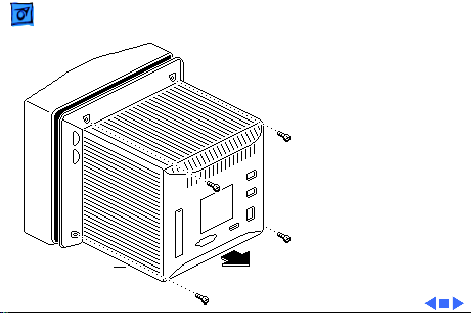
Rear Cover
No preliminary steps are
required before you begin
this procedure.
±
Rear Cover
Warning:
contains high voltage and a
high-vacuum picture tube.
To prevent serious injury,
review CRT safety in
Bulletins/Safety.
±
Warning:
grounding wriststrap until
after discharging the CRT.
Remove the four case screws
and lift off the rear cover.
This product
Never use a
Page 23
Take Apart EMI Shield - 2
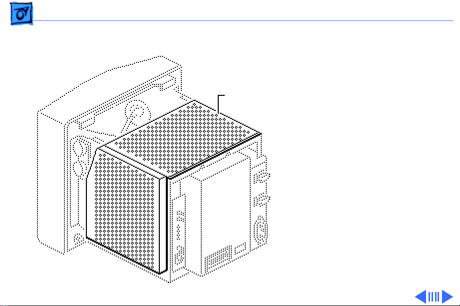
EMI Shield
Before you begin,
• Remove the rear cover
EMI Shield
• Discharge the CRT
±
Warning:
contains high voltage and a
high-vacuum picture tube.
To prevent serious injury,
review CRT safety in
Bulletins/Safety.
±
Warning:
grounding wriststrap until
after discharging the CRT.
This product
Never use a
Page 24
Take Apart EMI Shield - 3
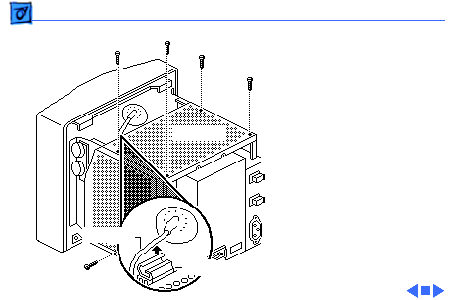
1 Remove the five screws
that secure the EMI
shield to the chassis.
±
2
EMI Shield
Anode Wire
Cable Clamp
Warning:
touch the anode wire to
remove it from the
shield.
Gently pull and twist the
shield to release the
anode wire from the
cable clamp.
Do not
Page 25
Take Apart CRT Board (C Board) - 4
CRT Board (C Board)
Before you begin,
• Remove the rear cover
• Remove the EMI shield
• Discharge the CRT
±
CRT Board
(C Board)
Warning:
contains high voltage and a
high-vacuum picture tube.
To prevent serious injury,
review CRT safety in
Bulletins/Safety.
±
Warning:
grounding wriststrap until
after discharging the CRT.
This product
Never use a
Page 26
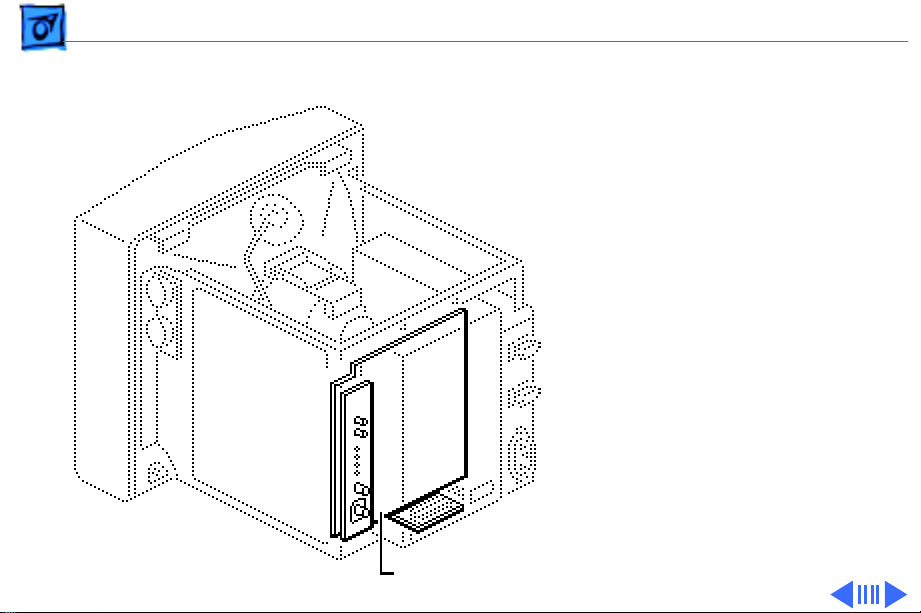
Take Apart CRT Board (C Board) - 5
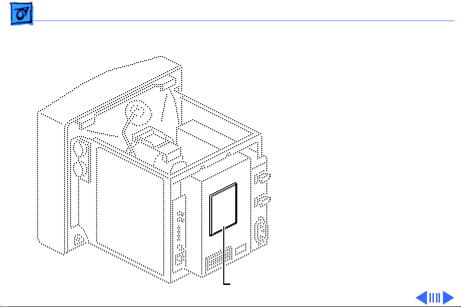
1 Pull off the metal video
board shield.
Video Board Shield
Page 27
Take Apart CRT Board (C Board) - 6
2 Remove the screw that
secures the black
ground wires to the video
color board frame.
3 Pull the CRT board
straight off the neck of
the CRT.
4
Caution:
Excessive force
might damage the video
board B connectors. If
the connectors are
difficult to remove, slip
Ground
Wires
a jeweler’s screwdriver
between the two halves
of the connector and
carefully pry them
CRT
Board
apart.
Page 28

Take Apart CRT Board (C Board) - 7
Note:
Some connector
Video Board B
locations are different on
the Rev. A and Rev. B
versions of the CRT
board.
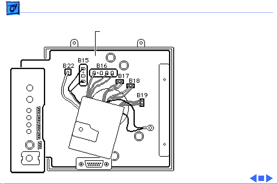
Disconnect the following
CRT board cable
connectors from video
board B:
• Gray, 1-wire cable
CRT Board
from B22
• White, 2-wire cable
from B15
• White, 4-wire cable
from B16
• Black, 2-wire cable
from B17
Page 29
Take Apart CRT Board (C Board) - 8
• Yellow, 2-wire cable
Video Board B
from B18
• Red, 2-wire cable
from B19
CRT Board
Page 30
Take Apart Video Color Board - 9
Video Color Board
Before you begin,
• Remove the rear cover
• Remove the EMI shield
• Discharge the CRT
• Remove the CRT board
±
Warning:
contains high voltage and a
high-vacuum picture tube.
To prevent serious injury,
review CRT safety in
Bulletins/Safety.
Video Color Board
This product
Page 31

Take Apart Video Color Board - 10
±
Video Color Board
(H Board)
Warning:
grounding wriststrap until
after discharging the CRT
Note:
The video color board
is an assembly composed of
three boards (H, B, and Q),
the metal frame that
supports the boards, and the
exterior I/O connector.
1 Remove the three screws
that secure the video
color board (H board) to
the metal chassis and
pull the board out
slightly.
Never use a
Page 32

Take Apart Video Color Board - 11
2
Caution:
Excessive force
may pull the connector
off the board. If the
connector is difficult to
disconnect, slip a
jeweler’s screwdriver
between the two halves
of the connector and
carefully pry them
apart.
Disconnect the following
connectors from video
color boards B and H.
• Yellow, 3-wire cable
from H10
• White, 3-wire cable
from H14
Video Color Board
(H Board)
Video Color Board
(B Board)
Page 33

Take Apart Video Color Board - 12
• Black, 3-wire cable
from H13
• Red, 3-wire cable
from H12
• White, 3-wire cable
from H11
• White, 3-wire cable
from B2
• Yellow, 4-wire cable
from B21
• Black, 4-wire cable
from B1
Video Color Board
(H Board)
Video Color Board
(B Board)
Page 34

Take Apart Video Color Board - 13
3 Remove the five screws
that secure deflection
board D to the chassis.
4 Squeeze together the
plastic clamps and
Plastic Clamps
Deflection Board D
release the deflection
board. Squeeze the
clamps one at a time; if
necessary, use
needlenose pliers.
Page 35

Take Apart Video Color Board - 14
Deflection Board D
5 Disconnect connectors
D-4 and D-5 from
deflection board D.
Note:
On the Rev. B
version of the deflection
board, the connectors
may begin with the
letter “B.”
Note:
Some connector
locations are different on
the Rev. A and Rev. B
versions of the video
color board.
Page 36

Take Apart Video Color Board - 15
6 Remove the four screws
that secure the metal
frame of the video color
board to the chassis, and
remove the video color
board.
Video Color Board
Page 37

Take Apart Deflection Board D, Rev. A - 16
Deflection Board D, Rev. A
Before you begin,
• Remove the rear cover
• Remove the EMI shield
• Discharge the CRT
±
Deflection Board D
(Rev. A)
Warning:
contains high voltage and a
high-vacuum picture tube.
To prevent serious injury,
review CRT safety in
Bulletins/Safety.
±
Warning:
grounding wriststrap until
after discharging the CRT. Ê
This product
Never use a
Page 38

Take Apart Deflection Board D, Rev. A - 17
1 Remove the five screws
that secure deflection
board D to the metal
chassis.
2 Squeeze together the
Plastic Clamps
plastic clamps and
release the deflection
Deflection Board D
board. Squeeze the
clamps one at a time; if
necessary, use
needlenose pliers.
3 Pull deflection board D
slightly away from the
chassis.
Page 39

Take Apart Deflection Board D, Rev. A - 18
Deflection Board D
4 Disconnect these
connectors from the
deflection board:
• White, 3-wire cable
from D11
• White, 2-wire cable
from D9
• Yellow, 3-wire cable
from D10
• Black, 4-wire cable
from D1
• Black, 3-wire cable
from D13
• White, 3-wire cable
from D14
• White(lg), 4-wire
cable from D3
Page 40

Take Apart Deflection Board D, Rev. A - 19
Deflection Board D
• Red, 4-wire cable
from D6
• White, 3-wire cable
from D2
• White, 4-wire cable
from D7
• Red, 3-wire cable
from D12
• White, 2-wire cable
from D5
• Gray, 1-wire cable
from D4
Page 41

Take Apart Deflection Board D, Rev. A - 20
5 Peel back the rubber
High-Voltage
Capacitor Housing
boot on the flyback wire
in the high-voltage
capacitor housing. Insert
pliers into the opening
in the capacitor housing
and grasp the wire as
close as possible to the
capacitor. Push in
(toward the capacitor)
Flyback
Wire
and rotate the wire 1/4
turn counterclockwise; then pull out
the wire.
6 Lift the deflection board
free.
Page 42

Take Apart Deflection Board D, Rev. B - 21
Deflection Board D, Rev. B
Before you begin,
• Remove the rear cover
• Remove the EMI shield
• Discharge the CRT
• Disconnect anode cap
±
Warning:
contains high voltage and a
high-vacuum picture tube.
To prevent serious injury,
review CRT safety in
Bulletins/Safety.
Deflection Board D
(Rev. B)
This product
Page 43

Take Apart Deflection Board D, Rev. B - 22
±
Plastic Clamps
Warning:
grounding wriststrap until
after discharging the CRT.
1 Remove the five screws
that secure deflection
board D to the chassis.
Never use a
Deflection Board D
2 Squeeze together the
plastic clamps and
release the deflection
board. Squeeze the
clamps one at a time; if
necessary, use
needlenose pliers.
3 Pull deflection board D
slightly away from the
chassis.
Page 44

Take Apart Deflection Board D, Rev. B - 23
Deflection Board D
4 Disconnect these cables
from the deflection
board:
• White, 3-wire cable
from D11
• White, 2-wire cable
from D9
• Yellow, 3-wire cable
from D10
• Black, 4-wire cable
from D1
• Black, 3-wire cable
from D13
• White, 3-wire cable
from D14
• White(lg), 4-wire
cable from D3
Page 45

Take Apart Deflection Board D, Rev. B - 24
Deflection Board D
• White, 3-wire cable
from D2
• White, 4-wire cable
from D7
• Red, 3-wire cable
from D12
• White, 2-wire cable
from D5
• Gray, 1-wire cable
from D4
Page 46

Take Apart Deflection Board D, Rev. B - 25
5 Remove the wires from
Deflection Board
the cable clamp.
Cable Clamp
6 Lift the deflection board
free.
Cable Wires
Page 47

Take Apart Power Supply - 26
Power Supply
Before you begin,
Power Supply
• Remove the rear cover
• Remove the EMI shield
• Discharge the CRT
±
Warning:
contains high voltage and a
high-vacuum picture tube.
To prevent serious injury,
review CRT safety in
Bulletins/Safety.
±
Warning:
grounding wriststrap until
after discharging the CRT.
This product
Never use a
Page 48

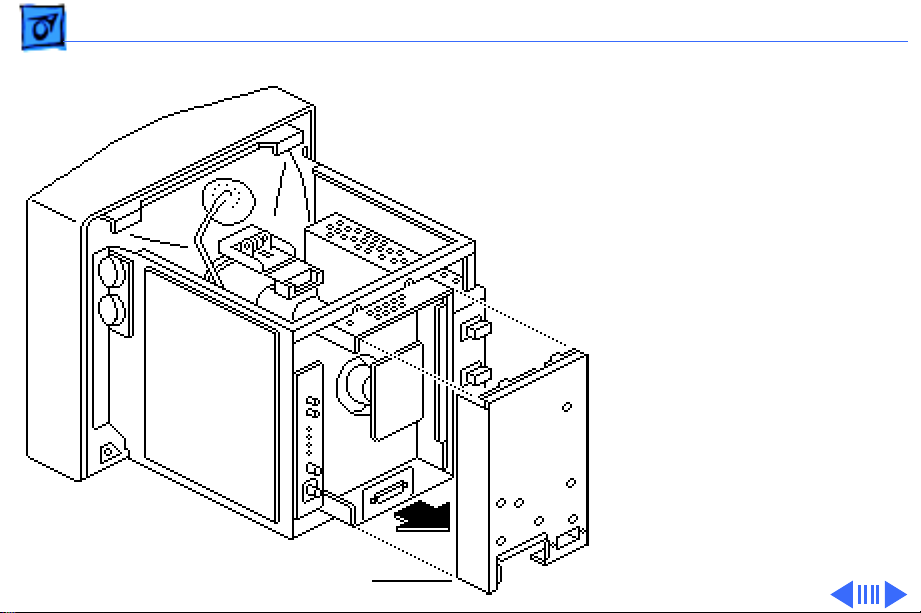
Take Apart Power Supply - 27
1 Remove the four
mounting screws and
slide the power supply
back slightly.
Power Supply
Page 49

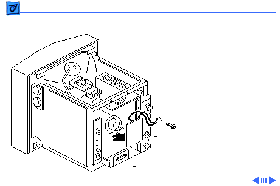
Take Apart Power Supply - 28
2 Disconnect the large
two-wire connector
from the top of the
power supply, and the
small four-wire
connector from the
front of the power
supply.
3 Slide the power supply
back and out of the
chassis.
Page 50

Take Apart Fuses - 29
Fuses
Before you begin,
• Remove the rear cover
• Remove the EMI shield
Fuses
• Discharge the CRT
• Remove the power supply
±
Warning:
contains high voltage and a
high-vacuum picture tube.
To prevent serious injury,
review CRT safety in
Bulletins/Safety.
±
Warning:
grounding wriststrap until
after discharging the CRT.
This product
Never use a
Page 51

Take Apart Fuses - 30
1 Remove the top screw
and washer and the end
screw from the power
supply cover. Lift off the
cover.
Power Supply
Page 52

Take Apart Fuses - 31
2 Remove a blown fuse by
prying up one end of the
fuse with your fingers
or a small flat-blade
screwdriver.
Note:
There are two fuses in
the power supply, F101
(6.3A/250V) and F102
(3.15A/250V). These fuses
are not interchangeable.
Page 53

Take Apart Contrast Control Board J - 32
Contrast Control Board J
Before you begin,
• Remove the rear cover
• Discharge the CRT
±
Warning: This product
contains high voltage and a
high-vacuum picture tube.
To prevent serious injury,
review CRT safety in
Contrast Control Board J
Bulletins/Safety.
±Warning: Never use a
grounding wriststrap until
after discharging the CRT.
Page 54

Take Apart Contrast Control Board J - 33
1 Disconnect the yellow 4-
wire cable from
connector J-21, and the
white 2-wire cable from
connector J-8.
Page 55

Take Apart Contrast Control Board J - 34
2 Pull off the two knobs,
and remove the two
mounting screws and the
contrast control board.
Replacement Note: Save
the knobs to put on the
replacement board.
Page 56

Take Apart High-Voltage Capacitor - 35
High-Voltage Capacitor
Before you begin,
• Remove the rear cover
• Discharge the CRT
• Disconnect anode cap
±Warning: This product
contains high voltage and a
high-vacuum picture tube.
To prevent serious injury,
review CRT safety in
Bulletins/Safety.
±Warning: Never use a
grounding wriststrap until
after discharging the CRT.
High-Voltage Capacitor
Page 57

Take Apart High-Voltage Capacitor - 36
1 Remove the four screws
that secure the metal
screen to the bottom of
the chassis.
2 Tip out the metal screen
and the attached highvoltage capacitor.
Page 58

Take Apart High-Voltage Capacitor - 37
High-Voltage
Capacitor Housing
Flyback
Wire
3 Peel back the flyback
wire’s rubber boot
from the opening in the
high-voltage capacitor
housing. Insert pliers
into the opening in the
capacitor housing and
grasp the wire as close
as possible to the
capacitor. Push in
(toward the capacitor)
and rotate the wire 1/4
turn counterclockwise; then pull out
the wire.
Page 59

Take Apart High-Voltage Capacitor - 38
Deflection Board D
4 Disconnect the gray wire
from its red 4-wire
connector at D-6 on the
deflection board.
Page 60

Take Apart High-Voltage Capacitor - 39
5 Lift off the metal screen
High-Voltage
Capacitor
with attached highvoltage capacitor.
6 Remove the two
mounting screws and the
high-voltage capacitor
from the screen.
Page 61

Take Apart Chassis - 40
Chassis
Chassis
Before you begin,
• Remove the rear cover
• Remove the EMI shield
• Discharge CRT
• Disconnect anode cap
±Warning: This product
contains high voltage and a
high-vacuum picture tube.
To prevent serious injury,
review CRT safety in
Bulletins/Safety.
±Warning: Never use a
grounding wriststrap until
after discharging the CRT.
Page 62

Take Apart Chassis - 41
Deflection Board D
Note: The chassis is not a
replaceable part. Perform
this procedure to access the
CRT or the LED.
1 Disconnect the white 2-
wire connector from D3
and the white 4-wire
connector from D9 on
deflection board D.
Note: On the Rev. B
version of the deflection
board the connectors
may begin with the
letter “B.”
Page 63

Take Apart Chassis - 42
2 Disconnect the white 2-
wire connector from the
contrast control board
J8.
3 Remove the wires from
the plastic cable clamps.
Page 64

Take Apart Chassis - 43
4 Pull the CRT board
straight off the neck of
CRT Board
the CRT.
5 Remove the four corner
screws that secure the
metal chassis to the
bezel. Lift off the chassis
with attached modules.
Chassis
Page 65

Take Apart CRT Assembly - 44
CRT Assembly
Before you begin,
• Remove the rear cover
• Remove the EMI shield
• Discharge the CRT
• Disconnect the anode cap
• Remove the chassis
±Warning: This product
contains high voltage and a
high-vacuum picture tube.
To prevent serious injury,
review CRT safety in
Bulletins/Safety.
CRT Assembly
Page 66

Take Apart CRT Assembly - 45
±Warning: Never use a
grounding wriststrap until
after discharging the CRT.
±Warning: If the CRT is
cracked or damaged, refer
to the CRT safety and
disposal instructions in
Bulletins/Safety.
Caution: The neck of the CRT
is easily damaged. Do not
grab the neck of the CRT to
remove it from the bezel.
Support the side of the CRT
with one hand, tip the bezel
to one side, and carefully
ease the CRT out of the bezel.
Page 67

Take Apart LED - 46
LED
Before you begin,
• Remove the rear cover
• Remove the EMI shield
• Discharge CRT
• Remove the anode cap
• Remove the chassis
±Warning: This product
contains high voltage and a
high-vacuum picture tube.
To prevent serious injury,
review CRT safety in
Bulletins/Safety.
LED
Page 68

Take Apart LED - 47
Front Bezel
±Warning: Never use a
grounding wriststrap until
after discharging the CRT.
Remove the screw that
secures the LED cable
assembly to the front bezel.
Lift out the LED.
LED Cable Assembly
Page 69

K
Service Source
Adjustments
AppleColor High-Resolution
RGB Monitor
Page 70

Adjustments Geometry - 1
Geometry
No preliminary steps are
required before you begin
this procedure.
Note:
Perform the geometry
adjustments in order.
Although the geometry
controls are shown here
with the rear cover
removed, you can access
them from the service
access panel at the rear of
the monitor.
Brightness
and Contrast
Knobs
Geometry Controls
Page 71

Adjustments Geometry - 2
±
Warning:
contains high voltage and a
high-vacuum picture tube.
To prevent serious injury,
review CRT safety in
Bulletins/Safety.
This product
Caution:
yoke adjustments on this
monitor. All such
adjustments have been set
by the manufacturer.
Do not attempt
Page 72

Adjustments Geometry - 3
Horizontal Size
Note:
Due to video features
and timing differences
across the Apple line of
Macintosh computers, the
width of the raster/image
area on the Hi-Res RGB
monitor may vary up to 3/
16 inch at each side of the
display. Perform the
horizontal size adjustment
to set the display to its
proper width.
1 Use Display Service
Utility to display the
All-White Screen test
pattern.
Page 73

Adjustments Geometry - 4
2 Using a plastic
screwdriver, adjust the
horizontal size control
until the raster width is
9 1/4 in. (± 1/8 in.) or
235 mm (± 2 mm).
Page 74

Adjustments Geometry - 5
Vertical Size
Note:
Adjust the horizontal
size before you adjust the
vertical size. The horizontal
adjustment can affect the
height of the raster.
1 Use Display Service
Utility to display the
Crosshatch II (white
background) test
pattern.
2 Using a plastic
screwdriver, adjust the
vertical-size control
until the raster height is
7 in. (± 1/8 in.) or 176
Page 75

Adjustments Geometry - 6
mm (± 2 mm).
Page 76

Adjustments Geometry - 7
Focus
1 Use Display Service
Utility to display the
Focus test pattern.
2 Using a plastic
screwdriver, adjust the
focus control for the best
clarity at points
halfway between the
center and the left and
right edges of the screen.
Page 77

Adjustments Video - 8
Video
Before you begin, remove
the following:
• Rear cover
• EMI shield
• Video board shield
±
Brightness
Knobs
and Contrast
Video Color Board
(H Board)
CRT Board
(C Board)
Video
Color
Board
(B Board)
Warning:
contains high voltage and a
high-vacuum picture tube.
To prevent serious injury,
review CRT safety in
Bulletins/Safety.
This product
Page 78

Adjustments Video - 9
±
Warning:
make adjustments from the
rear of the computer,
position a mirror to view
the computer screen. Do not
reach around the computer
to adjust the controls.
Note:
Perform the cutoff
adjustment whenever you
replace the CRT assembly,
deflection board D, or the
video color board.
Because you
Page 79

Adjustments Video - 10
1 Remove the video cable
from the back of the
monitor. Switch on the
monitor.
Note:
Perform the
cutoff and white balance
adjustments in a dimly
lit room after the
monitor has been on for
at least 10 minutes.
Brightness
2 Set the external (user)
contrast knob to
maximum and the
external brightness
knob to the center
(detent) position.
Contrast
Page 80

Adjustments Video - 11
Video Color Board (B Board)
Video Color Board (H Board)
SUB BRT SUB CONT
Cutoff
1 Using the plastic
screwdriver, adjust the
following controls on
the video color board (B
board) to midrange:
• B.BKG (R.BKG on Rev.
B version)
• G.BKG
• R.BKG (B.BKG on Rev.
B version)
• R.DRIVE
• G.DRIVE
• B.DRIVE
• SUB CONT
• SUB BRT
Page 81

Adjustments Video - 12
2 Set the voltmeter to
measure 140 volts DC.
3 Attach the voltmeter
ground lead (black lead)
to the monitor chassis.
4 Connect the voltmeter
red lead to the cathode
marked KR on the CRT
CRT Board
(C Board)
board (C board).
Gradually adjust the
R.BKG control until the
voltage measures 140 V
(± 2 V).
Page 82

Adjustments Video - 13
5 Connect the voltmeter
red lead to the pin
marked KG on the CRT
board (C board).
Gradually adjust the
G.BKG control until the
voltage measures 140 V
(± 2 V).
CRT Board
(C Board)
Page 83

Adjustments Video - 14
6 Connect the voltmeter
red lead to the pin
marked KB on the CRT
board (C board).
Gradually adjust the
B.BKG control until the
voltage measures 140 V
(± 2 V).
CRT Board
(C Board)
Page 84

Adjustments Video - 15
7
Note:
If you increase the
cutoff control
Video Color Board (B Board)
Video Color Board
(H Board)
(clockwise) too far, the
monitor might shut
down. If this happens,
switch off the monitor
Cutoff
and turn the cutoff
control all the way down
(counterclockwise).
Wait 30 seconds, switch
on the monitor, and
resume the adjustment.
Using a plastic
screwdriver, adjust the
SUB BRT
cutoff control until the
raster is just visible.
Page 85

Adjustments Video - 16
8 Turn the cutoff control
counterclockwise until
Video Color Board (B Board)
Video Color Board
(H Board)
the raster just
disappears.
Caution:
Once the cutoff
control on the video
Cutoff
color board (H board) is
correct, do not move it
again unless you repeat
the cutoff adjustment.
The life of the picture
tube decreases severely
if the cutoff adjustment
is incorrect.
SUB BRT
Page 86

Adjustments Video - 17
White Balance
Video Color Board
(H Board)
Cutoff
Video Color Board (B Board)
Caution:
cutoff is correct before you
proceed. The life of the
picture tube decreases
severely if the cutoff
adjustment is incorrect.
1 Switch off the monitor,
2 Use Display Service
Make sure the
connect the video cable,
and switch the monitor
back on.
Utility to display the
Gray Bars test pattern.
Page 87

Adjustments Video - 18
3 Using the plastic
screwdriver,
alternately adjust the
B.BKG, G.BKG, and R.BKG
Video Color Board
Video Color Board (B Board)
(H Board)
B.BKG
controls until
• The left (dark) three
bars have no colored
tint
• The leftmost bar is as
black as the screen
border
• You can barely
distinguish the second
bar from the black bar
G.BKG
• The third bar is a
dark gray
Note:
R.BKG
To achieve good
Page 88

Adjustments Video - 19
color balance, try
reducing the background
of the predominant color.
If necessary, increase
the other background
controls until you see no
color tint.
4
Important:
from light meter models
R77, L-248, and 246
differ. Please note
which meter you are
using before making
adjustments. (See
“Light Meter Setup.”)
Using the light meter and
a two-inch plastic
Readings
Page 89

Adjustments Video - 20
H Board
B Board
G.DRIVE
Light Meter
screwdriver, adjust the
G.DRIVE control until the
luminance of the
rightmost (brightest)
bar measures 24 foot
lamberts (± 3 foot
lamberts), which on the
light meter is
• Model R77: 19 on the
bottom scale
• Model L-248: 9 to 10
on the 2-10 scale
• Model 246: 19 on the
red scale
Important:
Over time,
light meter tolerances
can vary. If you doubt
Page 90

Adjustments Video - 21
your meter’s accuracy,
verify the readings with
a known-good light
meter or photometer.
B Board
5 Adjust the R.DRIVE and
H Board
B.DRIVE until you see no
predominant color in
the three right
(brightest) bars.
6 As necessary, repeat the
G.DRIVE, R.DRIVE, and
B.DRIVE adjustments.
R.DRIVE
G.DRIVE
B.DRIVE
Page 91

Adjustments Video - 22
7 If the left (darkest) bars
now show a predominant
color, readjust the
background controls
B Board
H Board
B.BKG
(B.BKG, G.BKG, and
R.BKG) of the two
nonpredominant colors
until you see only
shades of black and gray.
Note:
The white balance
is correct if
• You see no
predominant color
G.BKG
• The brightest bar
measures 24 foot
SUB CONTSUB BRT
R.BKG
lamberts (± 3 foot
lamberts) or 9 to 10
Page 92

Adjustments Video - 23
on light meter Model
L-248 or 19 on light
meter Model 246 or
19 on light meter
Model R77
• The left (darkest)
bars are black,
barely
distinguishable, and
dark gray.
If you desire additional
fine tuning, adjust the
sub-contrast and subbrightness controls in
the next steps.
Page 93

Adjustments Video - 24
Sub-Contrast
Adjust the SUB CONT
control so that the
B Board
H Board
SUB CONT
luminance in the middle of
the rightmost (brightest)
bar measures 24 foot
lamberts (± 3 foot
lamberts), which is
• Model L-248: middle of
the 9 scale
• Model 246: 19 on the red
scale
• Model R77: 19 on the
bottom scale
Page 94

Adjustments Video - 25
Important:
meter tolerances can vary.
If you doubt your meter’s
accuracy, verify the
readings with a known-good
light meter or photometer.
Over time, light
Page 95

Adjustments Video - 26
Sub-Brightness
Adjust the SUB BRT control
so that the leftmost bar is
B Board
H Board
SUB BRT
completely black and the
next bar is barely
distinguishable from the
black bar.
Page 96

Adjustments Light Meter Setup - 27
Light Meter Setup
This topic covers setup for
three light meter models:
R77, L-248, and 246.
Model R77 (Apple part
number 076-0310) is the
newest model available.
Model R77
The R77 light meter is
capable of reading luminance
from 10 to 1,000
footcandles (fc).
Before you begin, remove
the 10X multiplier plate
Page 97
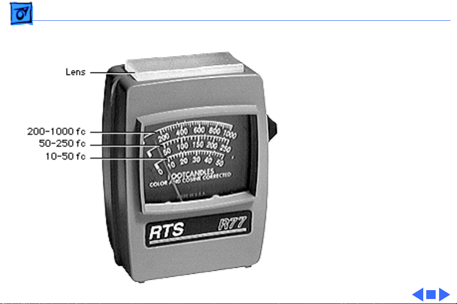
Adjustments Light Meter Setup - 28
from the lens.
Three scales are shown on
the light meter:
• 200-1000 fc
• 50-250 fc
• 10-50 fc
Because display screen
luminance typically ranges
from 10 to 50 fc, take
readings from the bottom
scale only.
Page 98

Adjustments Light Meter Setup - 29
To measure a display
screen’s luminance,
1 Set the scale switch to
the bottom position (to
set up the 10-50 fc
scale).
2 Place the lens against the
middle of the screen and
read the bottom scale.
Note:
When the light meter
is not in use, slide the scale
switch to its top position,
and store the meter in its
protective case.
Important:
light meter is giving false
If you suspect the
Page 99

Adjustments Light Meter Setup - 30
readings, verify the
readings with a known-good
light meter or photometer.
Also check the age of the R77
light meter by its four-digit
manufacturing date stamp
(such as 0398 for March
1998).
Caution:
meter can permanently
damage its accuracy. A
shock-damaged meter might
read incorrectly or its
pointer may not drop to
zero.
Dropping the
Page 100

Adjustments Light Meter Setup - 31
Side
Switch
Scale
Lens
Read
Button
Red Area
Model L-248
1 Press the red button on
the back of the light
meter. If the reading is
out of the red area,
replace the battery.
2 Move the side switch to
its lower position so that
the scale reads 2 through
10.
3 Uncover the lens of the
meter.
4 Place the lens against the
middle of the screen and
press the read button to
read the scale.
 Loading...