

Page 1

K
Service Source
AppleCD 150/300
Apple CD 150
Apple CD 300
Page 2

K
Service Source
Specifications
AppleCD 150/300
Page 3

Specifications Characteristics 150 - 1
Characteristics 150
Access Time
(Including Latency)
Data-Streaming
Rate
Block Rate
Average: 380 ms (typical)
Maximum (first to last block): 650 ms (typical)
Mode 1: 150K/sec.
Mode 2: 171K/sec.
75 blocks/sec.
Page 4

Specifications Characteristics 150 - 2
SCSI T ransfer Rate
Rotational Speed
Interfaces
Playback Medium
Approximately 1.5 MB/sec.
Approximately 230–530 rpm
One headphone jack; two SCSI 50-pin connectors; two audio output
jacks
12-cm optical disc installed in a CD caddy (any CD-ROM or audio
compact disc is compatible)
Page 5

Specifications Characteristics 300 - 3
Characteristics 300
Access Time
(Including Latency)
Data-Streaming
Rate
Block Rate
Normal speed: 360 ms (typical)
Double speed: 295 ms (typical)
Normal speed:
Mode 1: 150K/sec.
Mode 2: 171K/sec.
Double speed:
Mode 1: 300K/sec.
Mode 2: 342K/sec.
Normal speed: 75 blocks/sec.
Double speed: 150 blocks/sec.
Page 6

Specifications Characteristics 300 - 4
SCSI T ransfer Rate
Rotational Speed
Interfaces
Playback Medium
Formats
Approximately 2.5 MB/sec.
Normal speed: Approximately 230–530 rpm
Double speed: Approximately 460–1,060 rpm
One headphone jack; two SCSI 50-pin connectors; two audio output
jacks
12-cm optical disc installed in a CD caddy (any CD-ROM or audio
compact disc is compatible)
Multi-session Kodak Photo CD (QuickTime required); ISO 9660/
High Sierra; Macintosh HFS; CD-ROM XA (requires additional
ADPCM hardware to read compressed audio); CD+G; CD+MIDI;
standard audio CDs; CD digital audio data via SCSI bus
Page 7

Specifications Capacity - 5
Capacity
Data Capacity
Recording Surfaces
Data/Block
(Available to User)
Blocks per Disc
Mode 1: 656 MB
Mode 2: 748 MB
1
Mode 1: 2,048 bytes
Mode 2: 2,336 bytes
More than 270,000
Page 8

Specifications Audio Playback - 6
Audio Playback
Playing Time
Frequency Response
More than 1 hr.
20–20,000 Hz
Page 9

Specifications Environmental - 7
Environmental
Operating
Temperature
Relative Humidity
Storage
Temperature
41–104°F (5–40°C)
AppleCD 150: 10–90% noncondensing
AppleCD 300: 5–90% noncondensing
–22 to 122°F (–30 to 50°C)
Page 10

Specifications Electrical - 8
Electrical
Line V oltage
Frequency
Power Consumption
100–240 VAC
50–60 Hz
AppleCD 150: 0.25 A
AppleCD 300: 0.28 A
Page 11

Specifications Physical - 9
Physical
Dimensions
AppleCD 150
AppleCD 300
Weight
AppleCD 150:
AppleCD 300:
Height: 1.95 in. (4.9 cm)
Width: 7 in. (17.75 cm)
Depth: 12.9 in. (32.5 cm)
Height: 1.96 in. (5.0 cm)
Width: 7 in. (17.75 cm)
Depth: 13.1 in. (33.4 cm)
6.5 lb. (2.9 kg)
6.29 lb. (2.85 kg)
Page 12

K
Service Source
Troubleshooting
AppleCD 150/300
Page 13

Troubleshooting General/ - 1
General
The Symptom Charts included in this chapter will help you
diagnose specific symptoms related to your product. Because cures
are listed on the charts in the order of most likely solution, try
the first cure first. Verify whether or not the product continues to
exhibit the symptom. If the symptom persists, try the next cure.
(Note: If you have replaced a module, reinstall the original module
before you proceed to the next cure.)
If you are not sure what the problem is, or if the Symptom Charts
do not resolve the problem, refer to the Flowchart for the product
family.
For additional assistance, contact Apple Technical Support.
Page 14

Troubleshooting Symptom Charts - 2
Symptom Charts
Green power light is
not on
CD-ROM drive does
not accept disc
Headphone jack does
not operate correctly
Volume control does
not operate correctly
1 Replace power supply.
2 Replace drive mechanism.
1 Replace disc (if dirty or damaged).
2 Replace drive mechanism.
1 Replace drive mechanism.
2 Replace power supply.
Replace drive mechanism.
Page 15

Troubleshooting Symptom Charts - 3
Speaker jacks do not
operate
Macintosh cannot
mount CD-ROM drive
1 Replace drive mechanism.
2 Replace audio-out assembly.
3 Replace power supply.
1 Replace drive mechanism.
2 Replace power supply.
3 Replace SCSI-device-to-case cable.
4 Replace SCSI select switch.
Page 16

K
Service Source
T ak e Apart
AppleCD 150/300
Page 17

Take Apart - 1
The CD-ROM drive is a
mechanical device with
moving parts. Rough
handling can cause
mechanical failures. Follow
these guidelines when you
handle or repair the
CD-ROM drive:
• Switch off the power and
make sure no SCSI
devices are attached to
the drive.
• Place the drive on a soft,
grounded surface before
starting repairs.
• Never transport the
drive with a CD-ROM
disc or caddy inside.
Page 18

Take Apart - 2
• Use the original shipping
containers when you
transport the drive.
• Never place an AppleCD
300 drive mechanism in
an AppleCD 150 case. The
SCSI-device-to-case
cable will not connect
correctly.
Page 19

Take Apart Top Case Guidelines - 3
Top Case Guidelines
Top Case
No preliminary steps are
required before you begin
this procedure.
1 Remove the six case
screws.
2 Lift off the top case.
Page 20

Take Apart CD-ROM Drive - 4
CD-ROM Drive
Before you begin, remove
the top case:
CD-ROM Drive
Caution:
precautions in Bulletins/
Safety.
Review the ESD
Page 21

Take Apart CD-ROM Drive - 5
1 Remove the four drive
mounting screws from
the bottom of the case.
Page 22

Take Apart CD-ROM Drive - 6
SCSI Select
Switch Cable
Audio-Out
Cable
SCSI-Device-to-Case Cable
Power Cable
Ridged Edge
2 Hold the drive and turn
over the case.
3 Lift the back of the drive
and disconnect the
following cables:
• Audio-out cable
• SCSI select switch
cable
• SCSI-device-to-case
cable
• Power cable
4 Remove the drive from
the case.
Replacement Caution:
Replace the power cable
connector ridged edge up.
Page 23

Take Apart CD-ROM Drive - 7
Audio-Out Cable
Jumpers
ID Select
Parity
SCSI Select Switch Cable
Replacement Note:
Route the
power cable beneath the
SCSI-device-to-case cable.
Replacement Note:
If you are
replacing a defective drive
with a new drive, remove
the jumpers over the left
three pairs of pins in the
new drive’s SCSI select
switch connector.
Replacement Note:
To
reconnect the SCSI select
switch cable, insert the
cable connector on the left
four pairs of pins in the
drive connector. Make sure
Page 24

Take Apart CD-ROM Drive - 8
the looped wire attached to
the connector faces the
audio-out cable.
Page 25

Take Apart Power Supply - 9
Power Supply
Before you begin, remove
the following:
• Top case
Power Supply
• CD-ROM drive
Page 26

Take Apart Power Supply - 10
1 Remove the two power
supply mounting screws
from the bottom of the
case.
Page 27

Take Apart Power Supply - 11
2 Hold the power supply
and turn over the case.
Power Cable
3 Untape the cables from
the top of the power
Ground Wire Screw
supply.
4 Remove the ground wire
screw.
5 Lift the end of the power
supply farthest from
the power cable, release
the locking tab, and
disconnect the power
cable.
6 Remove the power
supply.
Page 28

Take Apart Power Supply - 12
Replacement Note:
the ground wire screw
before reconnecting the
power cable.
Replace
Page 29

Take Apart SCSI-Device-to-Case Cable - 13
SCSI-Device-toCase Cable
Before you begin, remove
SCSI-Device-to-Case Cable
the:
• Top case
Caution:
precautions in Bulletins/
Safety.
Review the ESD
Page 30

Take Apart SCSI-Device-to-Case Cable - 14
1 Remove the four drive
mounting screws from
the bottom of the case.
Page 31

Take Apart SCSI-Device-to-Case Cable - 15
2 Hold the drive and turn
over the case.
3 Lift the back of the drive
and disconnect the SCSIdevice-to-case cable.
4 Remove the four cable
mounting screws.
5 Pull the cable through
the rear panel and out of
the case.
SCSI-Device-to-Case Cable
Page 32

Take Apart Rear Panel - 16
Rear Panel
Before you begin, remove
the top case.
Rear Panel
Caution:
precautions in Bulletins/
Safety.
Review the ESD
Page 33

Take Apart Rear Panel - 17
1 Remove the four drive
mounting screws from
the bottom of the case.
Page 34

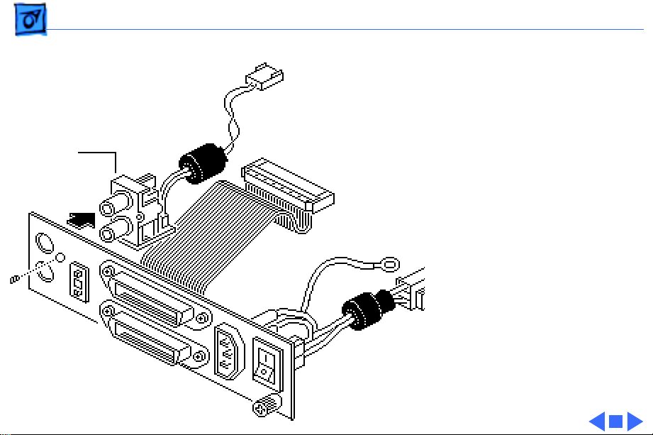
Take Apart Rear Panel - 18
2 Hold the drive and turn
SCSI Select
Switch Cable
Audio-Out
Cable
SCSI-Device-to-Case Cable
Power Cable
over the case.
3 Lift the back of the CD-
ROM drive and
disconnect the following
cables:
• Audio-out cable
• SCSI select switch
cable
• SCSI-device-to-case
cable
• Power cable
4 Remove the ground wire
screw.
Page 35

Take Apart Rear Panel - 19
Rear Panel
Replacement Note:
Replace the ground wire
screw before
reconnecting the power
cable.
5 Remove the two rear
panel mounting screws.
6 Remove the rear panel.
Page 36

Take Apart Rear Panel - 20
Looped
Wire
Audio-Out Cable
SCSI Select
Switch Cable
0 1 2
ID Select
Parity
Replacement Note:
To
reconnect the SCSI select
switch cable, insert the
cable connector on the left
four pairs of pins in the
drive connector. Make sure
the looped wire attached to
the connector faces the
audio-out cable.
Page 37

Take Apart Power Switch/Plug Assembly - 21
Power Switch/ Plug Assembly
Before you begin, remove
the following:
• Top case
• Rear panel
Power Switch/Plug Assembly
Page 38

Take Apart Power Switch/Plug Assembly - 22
1 Using a small flat-blade
screwdriver, depress
the bottom latch on the
power plug and push the
plug through the
opening as far as it will
go.
2 Depress the top latch on
the power plug and push
out the plug.
3 Repeat the procedure
for the power switch.
Power Plug
Power Switch
Page 39

Take Apart Power Switch/Plug Assembly - 23
4 Transfer the wires of the
power switch cable
across the small channel
to the power plug
opening.
5 Remove the power
switch/power plug
assembly through the
power plug opening.
Page 40

Take Apart Audio-Out Assembly - 24
Audio-Out Assembly
Before you begin, remove
the following:
Audio-Out Assembly
• Top case
• Rear panel
Page 41
Take Apart Audio-Out Assembly - 25
1 Remove the mounting
screw.
2 Remove the audio-out
assembly from the rear
Audio-Out
Assembly
panel.
Page 42

Take Apart SCSI Select Switch - 26
SCSI Select Switch
Before you begin, remove
SCSI Select Switch
the following:
• Top case
• Rear panel
• Audio-out assembly
Page 43

Take Apart SCSI Select Switch - 27
Note:
Use a rocking motion
to work the switch out of the
opening in the rear panel.
1 Using a small flat-blade
screwdriver, depress
one of the two switch
latches and push the
switch through the
Switch Latch
opening as far as it will
go.
2 Depress the other latch
and push out the switch
as far as it will go.
3 Repeat the procedure
SCSI Select Switch
until the switch works
free.
Page 44

Take Apart SCSI Select Switch - 28
4 Remove the switch
assembly from the rear
panel.
Page 45

Take Apart Front Panels - 29
Front Panels
Before you begin, remove
the top case.
Front Panel
Front Panel
Caution:
precautions in Bulletins/
Safety.
Review the ESD
Page 46

Take Apart Front Panels - 30
1 Remove the four drive
mounting screws from
the bottom of the case.
Page 47

Take Apart Front Panels - 31
2 Hold the drive and turn
over the case.
Left Front Panel
3 Lift the front of the
drive.
4 Pull the left front panel
straight up as far as it
will go and remove it
from the case.
5 Repeat for the right
front panel.
Right Front Panel
Page 48

Take Apart Bottom Case - 32
Bottom Case
Before you begin, remove
the following:
• Top case
Bottom Case
• CD-ROM drive
• Power supply
• Rear panel
To replace the bottom case,
perform the steps
referenced above.
Page 49

K
Service Source
Exploded V ie w
AppleCD 150/300
Page 50

Exploded View 1
SCSI-Device-to-Case Cable
Power Supply
Audio-Out
Assembly
SCSI Select Switch
Rear Panel
Top Case
CD-ROM Drive
Front Panels
Bottom Case
Power Switch/Plug Assembly
Page 51

K
Service Source
Additional Procedures
AppleCD 150/300
Page 52

Additional Procedures Fuse - 1
Fuse
Before you begin, remove
the following:
• Top case
• Rear panel
Fuse
Page 53

Additional Procedures Fuse - 2
Using a small flat-blade
screwdriver, pry the fuse
from the holder.
Replacement Note:
is not a service part.
Replace the fuse with type
MT4 250V2A, available at
most electronic stores.
The fuse
 Loading...