

Page 1

K
Service Source
Workgroup Server 9150
Workgroup Server 9150
Workgroup Server 9150/120
Page 2
K
Service Source
Basics
Workgroup Server 9150
Page 3
Basics Rear Panel Connectors - 1
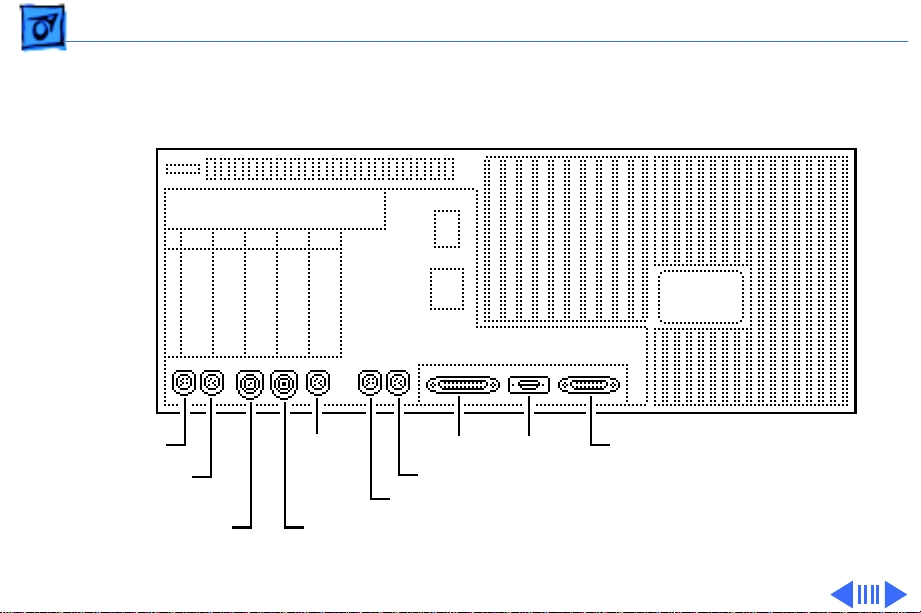
Rear Panel Connectors
Sound Out
Sound In
Sound In Left
ADB
Sound In Right
Ethernet
SCSI DB-15 Video
Modem
Printer
Page 4

Basics Logic Board Connectors - 2
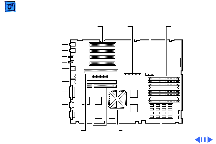
Logic Board Connectors
Note:
The order of the cache and ROM SIMMs will vary
according to the manufacturing date of the logic board. Be
sure to correctly identify the cache SIMM, which has four
chips on both sides, and remove it before returning the logic
board to Apple for repair. Do NOT remove the ROM SIMM
before returning the logic board.
Page 5
Basics Logic Board Connectors - 3
WS 9150
NuBus
Slots
Sound Out
Sound In
Sound In Left
Sound In Right
ADB
Printer
Modem
SCSI
Ethernet
DB-15 Video
Internal
SCSI
Connector
Floppy
Connector
DRAM
SIMMs
PDS Slot
Cache/ROM
SIMM Slots
PowerPC
601 Chip
16 MB Soldered DRAM
Page 6

Basics Logic Board Connectors - 4
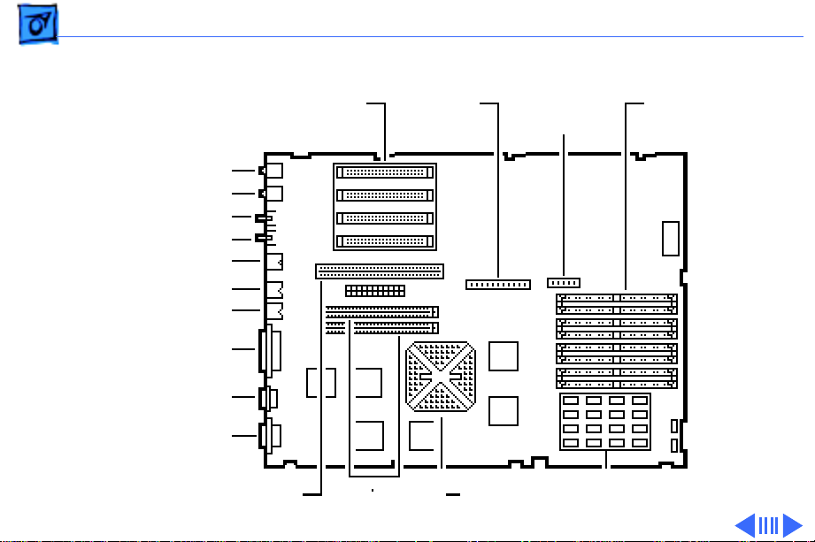
Note:
The order of the cache and ROM SIMMs will vary
according to the manufacturing date of the logic board. Be
sure to correctly identify the cache SIMM, which has four
chips on both sides, and remove it before returning the logic
board to Apple for repair. Do NOT remove the ROM SIMM
before returning the logic board.
Page 7
Basics Logic Board Connectors - 5
WS 9150/120
NuBus
Slots
Sound Out
Sound In
Sound In Left
Sound In Right
ADB
Printer
Modem
SCSI
Ethernet
DB-15 Video
Internal
SCSI
Connector
Floppy
Connector
DRAM
SIMMs
PDS Slot
Cache/ROM
SIMM Slots
PowerPC
601 Chip
8 MB Soldered DRAM
Page 8

Basics Logic Board Connectors - 6
Important:
The WS 9150/120 logic board has a
thermoelectric cooling device that attaches directly to the
microprocessor's heatsink. You can identify this cooling
device by the black and red wires that run to the right of the
heatsink and plug into the logic board via a keyed connector.
This device is not a serviceable item. Do not unplug this
device or you may damage the logic board. Also note that the
order of the cache and ROM SIMMs may vary. Be sure to
correctly identify the cache SIMM and remove it before
returning the logic board to Apple for repair. Do NOT
remove the ROM SIMM before returning the logic board.
Page 9

Basics RAID Information - 7
RAID Information
Apple RAID Software
Apple RAID (Redundant Array of Independent Disks)
software protects data from loss during a disk failure and
enhances the speed of data storage and retrieval. It is
available for all Power Macintosh Workgroup servers.
Data protection is achieved through disk mirroring, a data
storage scheme in which identical data is stored on two
different disks. Apple RAID can also be configured for disk
striping, a data storage scheme in which successive units of
data are transferred to several disks at one time.
Page 10

Basics RAID Information - 8
If you plan to install the Apple RAID software on an existing
Power Macintosh Workgroup Server, or if you are
reinitializing an existing Apple RAID drive, keep in the mind
the following:
• If you wish to use your server’s startup disk for Apple
RAID, do not install the Apple RAID program on your startup
disk until you have initialized and set up new volumes on
that disk. Before you initialize the startup disk, backup all
valuable data.
• You must reinitialize all disks on which you will use Apple
RAID volumes. Initializing with Apple RAID removes all
data, so be sure to backup your disks first.
Page 11

Basics RAID Information - 9
• The Apple RAID CD contains the facilities to reinstall your
system software. However, if you have made any
customizations to your system files, such as adding
extension files, control panels, or preference files, then
back up your system files now. Back them up in such a way
that you can restore your system files separately from the
non-system files on your disk. You will later restore your
system files using the backup copy rather than the System
Installer on the RAID CD, so that you preserve your system
customizations.
• Apple HD SC Setup does not recognize Apple RAID volumes.
If you want to remove or resize volumes on Apple RAID
disks, use the Apple RAID program.
Page 12
K
Service Source
Specifications
Workgroup Server 9150
Page 13

Specifications Processor - 1
Processor
CPU
9150:
9150/120:
80 MHz PowerPC 601 RISC microprocessor
Built-in MMU and FPU
32K of on-chip cache memory
Requires system software version 7.1.2 or later
120 MHz PowerPC 601 RISC microprocessor
Built-in MMU and FPU
32K of on-chip cache memory
Requires system software version 7.5 or later
Page 14

Specifications Memory - 2
Memory
RAM
9150:
9150/120:
ROM
8 MB RAM soldered on logic board, expandable to 264 MB via 8
SIMM sockets on logic board*
16 MB RAM soldered on logic board, expandable to 264 MB via 8
SIMM sockets on logic board*
*SIMMs must be installed in pairs of the same size and speed.
The SIMMs must be 80 ns or faster, 72-pin noncomposite
SIMMs.
4 MB installed on a SIMM socket
Page 15

Specifications Memory - 3
VRAM
Cache
9150:
9150/120:
Clock/Calendar
None; DRAM video support provided on logic board
32K on-chip cache; 512K level 2 cache SIMM
32K on-chip cache; 1 MB level 2 cache SIMM
CMOS custom chip with long-life lithium battery
Page 16

Specifications Disk Storage - 4
Disk Storage
Floppy Drive
Hard Drive
9150:
9150/120:
Tape Drive
1.4 MB Apple SuperDrive Manual Insert
500 MB, 1 GB, or 2 GB hard drive standard; room for a total of
five internal hard drives
Two 1 GB hard drives or one 2 GB hard drive standard; room for a
total of five internal hard drives
Optional DDS-2 DAT tape drive,120 M tape supported
Page 17

Specifications Disk Storage - 5
CD-ROM Drive
9150:
9150/120:
Internal AppleCD 300 Plus CD-ROM drive standard
Internal AppleCD 600 CD-ROM drive standard
Page 18

Specifications I/O Interfaces - 6
I/O Interfaces
SCSI
Serial
Apple Desktop Bus
Ethernet
One SCSI port; DB-25 connector
Supports maximum of seven internal and seven external SCSI
devices
Two RS-232/RS-422 LocalTalk/GeoPort serial ports; mini DIN-
9 connectors (backward compatible with mini DIN-8
connectors)
One Apple Desktop Bus (ADB) port; mini-Din-4 connector
Maximum power draw 500 mA; maximum of three devices total
One Ethernet port; AAUI-15 connector
Page 19

Specifications I/O Interfaces - 7
Expansion Slot
NuBus
Video
One Power Macintosh video slot; 182-pin connector
(Terminator card
Four slots support long or short expansion cards; 96-pin Euro-
DIN connectors
One DB-15 DRAM-based video port on logic board
must
be installed)
Page 20

Specifications I/O Interfaces - 8
Sound
8-bit stereo input; 16-bit stereo output
Sample rates of 48, 44.1, 24, and 22.05 kHz
Input/output line level: 1 V peak-to-peak
Input/output signal-to-noise ratio (SNR): 82 dB with no audible
discrete tones
Bandwidth: 20 Hz–20 kHz ± 2 dB) at 44.100 kHz sample rate
THD+N (total harmonic distortion plus noise): less than
0.05%, measured 20Hz–20 kHz with a 1-Vrms sine wave
input
Page 21

Specifications I/O Devices - 9
I/O Devices
Keyboard
Mouse
Microphone
Standard, extended, or adjustable keyboard
Keyboard draws 25–80 mA, depending on model of keyboard
ADB Mouse II; Draws up to 10 mA
Electret, omnidirectional; output voltage is 4 mV, peak to peak,
at normal value; does not use Apple PlainTalk microphone
Page 22

Specifications Video Display - 10
Video Display
Video Support
Supports monochrome, color, VGA, and SVGA formats, including
• Macintosh 12" Monochrome Display (640 x 480)
• Macintosh 12" RGB Display (512 x 384)
• AppleColor High-Resolution RGB 14" Monitor (640 x 480)
• Apple AudioVision 14 Display (640 x 480)
• Macintosh Color Display (640 x 480)
• Macintosh 15" Portrait Display (640 x 870)
• Macintosh 16" Color Display (832 x 624)
Page 23

Specifications Electrical - 11
Electrical
A/C Line Input Voltage
Input Line Frequency
Input Power
Power Supply DC Output
100–240 VAC; RMS single phase, automatically configured
50–60 Hz, single phase
600 W maximum, not including monitor power
303 W maximum
Page 24

Specifications Physical - 12
Physical
Dimensions
Weight
Height: 16.8 in. (473 mm)
Width: 8.9 in. (224 mm)
Depth: 20.6 in. (523 mm)
36 lb., 12 oz. (16.7 kg) without hard drive
Page 25

Specifications Environmental - 13
Environmental
Operating Temp
Storage Temp
Relative Humidity
Altitude
50–104° F (10–35° C)
–40 to 116.6° F (–40 to 47° C)
20–80% noncondensing
0–10,000 ft. (0–3048 m)
Page 26

K
Service Source
Troubleshooting
Workgroup Server 9150
Page 27

Troubleshooting General - 1
General
The Symptom Charts included in this chapter will help you
diagnose specific symptoms related to your product. Because cures
are listed on the charts in the order of most likely solution, try
the first cure first. Verify whether or not the product continues to
exhibit the symptom. If the symptom persists, try the next cure.
(Note: If you have replaced a module, reinstall the original module
before you proceed to the next cure.)
If you are not sure what the problem is, or if the Symptom Charts
do not resolve the problem, refer to the Flowchart for the product
family.
For additional assistance, contact Apple Technical Support.
Page 28

Troubleshooting Cleaning Procedure for Card Connectors - 2
Cleaning Procedure for Card Connectors
A small number of cards for the Workgroup Server 9150 may
contain residue on the gold edge connector pins, which may cause a
variety of intermittent symptoms.
To correct the problem, inspect the connector pins with a
magnifying glass. If you find residue, use a pencil eraser to gently
clean the pins.
Page 29

Troubleshooting Symptom Charts/Power Supply - 3
Symptom Charts
Power Supply
System does not
power up
1 Reset logic board. (Refer to Additional Procedures.)
2 Reseat ROM, RAM, and cache SIMMs, and reseat terminator
card.
3 Replace power supply.
4 Replace logic board.
Page 30

Troubleshooting Symptom Charts/Error Chords - 4
Error Chords
One-part error
chord sounds during
startup sequence
1 Disconnect SCSI data cable from hard drive and reboot
system. If startup sequence is normal, initialize hard drive.
If error chord still sounds, replace hard drive.
2 Disconnect floppy drive cable from floppy drive and reboot
system. If startup sequence is normal, replace floppy drive.
3 Reseat ROM, RAM, and cache SIMMs, and reseat terminator
card.
4 Replace logic board. Retain customer’s SIMMs.
Page 31

Troubleshooting Symptom Charts/System - 5
System
Does not power on;
screen is black, fan is
not running, and LED
is not lit
1 Check power cables.
2 Plug monitor directly into wall socket, and verify that
monitor has power.
3 Reset logic board. (Refer to Additional Procedures.)
4 Reseat ROM, RAM, and cache SIMMs, and reseat terminator
card.
5 Replace power cord.
6 Replace power supply.
7 Replace logic board. Retain customer’s SIMMs.
Page 32

Troubleshooting Symptom Charts/System
(Continued)
- 6
Clicking, chirping,
or thumping
System
1 Replace power supply.
2 Reseat ROM, RAM, and cache SIMMs, and reseat terminator
3 Replace logic board. Retain customer’s SIMMs.
4 Replace floppy drive cable.
5 Replace floppy drive.
(Continued)
card.
Page 33

Troubleshooting Symptom Charts/System
(Continued)
- 7
System shuts down
intermittently
System
1 Make sure air vents are clear. Thermal protection circuitry
2 Replace power cord.
3 Check battery. Refer to “Battery Verification” in Additional
4 Replace power supply.
5 Reseat ROM, RAM, and cache SIMMs, and reseat terminator
6 Replace logic board. Retain customer’s SIMMs.
(Continued)
may shut down system. After 30 to 40 minutes, system
should be OK.
Procedures.
card.
Page 34

Troubleshooting Symptom Charts/System
(Continued)
- 8
System
intermittently
crashes or hangs
System
1 Verify that system software is version 7.1.2 or later
2 Verify SIMMs are noncomposite and installed in like pairs
3 Verify software is known-good and Power Mac compatible.
4 Verify a terminator or video card is installed in the PDS slot.
5 Clear parameter RAM. Hold down <Command> <Option> <P>
6 Replace DRAM SIMMs. Refer to Memory manual.
7 Reseat ROM, RAM, and cache SIMMs, and reseat terminator
8 Replace cache SIMM or DIMM.
9 Replace logic board. Retain SIMMs.
10 Replace power supply.
(Continued)
(9150) or 7.5 or later (9150/120).
(same size/speed).
<R> during startup but before “Welcome to Macintosh”
appears.
card.
Page 35

Troubleshooting Symptom Charts/System
(Continued)
- 9
During startup,
following message is
displayed, “This
startup disk will not
work on this
Macintosh model.”
System
1 Verify that startup disk is good.
2 Attach LED cable to logic board.
3 Replace LED cable.
4 Reseat ROM, RAM, and cache SIMMs, and reseat terminator
5 Replace logic board. Retain customer’s SIMMs.
(Continued)
card.
Page 36

Troubleshooting Symptom Charts/Video - 10
Video
Screen is black, audio
and drive operate, fan
is running, and LED is
lit
1 Adjust brightness on monitor.
2 Replace video cable.
3 Try using known-good RAM SIMMs.
4 Replace video card (if present).
5 Clear parameter RAM. Hold down <Command> <Option> <P>
<R> during startup but before “Welcome to Macintosh”
appears.
6 Replace SIMMs.
7 Replace monitor. Refer to appropriate monitor manual to
troubleshoot defective monitor.
8 Reseat ROM, RAM, and cache SIMMs, and reseat terminator
card.
9 Replace logic board. Retain customer’s SIMMs.
10 Replace power supply.
Page 37

Troubleshooting Symptom Charts/Video
(Continued)
- 11
Screen is black, audio
and drive do not
operate, but fan is
running and LED is lit
Video
1 Replace video cable.
2 Replace video card (if present).
3 Replace SIMMs.
4 Reseat ROM, RAM, and cache SIMMs, and reseat terminator
5 Replace logic board. Retain customer’s SIMMs.
6 Replace power supply.
(Continued)
card.
Page 38

Troubleshooting Symptom Charts/Video
(Continued)
- 12
Partial or whole
screen is bright and
audio is present, but
no video information
is visible
Video
1 Replace video cable.
2 Replace video card (if present).
3 Clear parameter RAM. Hold down <Command> <Option> <P>
4 Replace monitor. Refer to appropriate monitor manual to
5 Reseat ROM, RAM, and cache SIMMs, and reseat terminator
6 Replace logic board. Retain customer’s SIMMs.
(Continued)
<R> during startup but before “Welcome to Macintosh”
appears.
troubleshoot defective monitor.
card.
Page 39

Troubleshooting Symptom Charts/Floppy Drive - 13
Floppy Drive
Internal floppy drive
does not operate
1 Replace disk with known-good floppy disk.
2 Replace floppy drive cable.
3 Replace floppy drive.
4 Reseat ROM, RAM, and cache SIMMs, and reseat terminator
card.
5 Replace logic board. Retain customer’s SIMMs.
6 Replace power supply.
Page 40

Troubleshooting Symptom Charts/Floppy Drive
(Continued)
- 14
During system
startup, disk ejects;
display shows icon
with blinking “X”
Floppy Drive
1 Replace disk with known-good system disk.
2 Clear parameter RAM. Hold down <Command> <Option> <P>
<R> during startup but before “Welcome to Macintosh”
appears.
3 Replace floppy drive cable.
4 Replace floppy drive.
5 Reseat ROM, RAM, and cache SIMMs, and reseat terminator
card.
6 Replace logic board. Retain customer’s SIMMs.
(Continued)
Page 41

Troubleshooting Symptom Charts/Floppy Drive
(Continued)
- 15
Floppy Drive
Does not eject disk 1 Switch off computer. Hold mouse button down while you
switch computer on.
2 Replace floppy drive cable.
3 Replace floppy drive.
4 Reseat ROM, RAM, and cache SIMMs, and reseat terminator
card.
5 Replace logic board. Retain customer’s SIMMs.
Attempts to eject
disk, but doesn’t
1 Push disk completely in.
2 Reseat floppy drive bezel and drive so bezel slot aligns
correctly with drive.
3 Eject disk manually.
4 Replace floppy drive.
(Continued)
Page 42

Troubleshooting Symptom Charts/Floppy Drive
(Continued)
- 16
Internal floppy drive
runs continuously
MS-DOS drive does
not recognize a disk
formatted on a 1.4 MB
drive
Floppy Drive
1 Replace disk with known-good floppy disk.
2 Replace floppy drive cable.
3 Replace floppy drive.
4 Reseat ROM, RAM, and cache SIMMs, and reseat terminator
card.
5 Replace logic board. Retain customer’s SIMMs.
To read and write files with either MS-DOS or 1.4 MB drive,
format all disks with MS-DOS drive first.
(Continued)
Page 43

Troubleshooting Symptom Charts/Hard Drive - 17
Hard Drive
Single internal hard
drive does not
operate; drive
doesn’t spin
1 Update driver software of hard drive using HD-SC Setup.
(Note: Use Apple RAID to update driver on RAID WS 9150
drives.)
2 Reinstall system software.
3 Replace hard drive power cable.
4 Replace SCSI cable.
5 Replace hard drive. (Note: If replacing an Apple WS 9150
RAID drive, you must reinstall the RAID software on the
drive. See “RAID Information” in Basics.)
6 Replace power supply.
Page 44

Troubleshooting Symptom Charts/Hard drive
(Continued)
- 18
No internal SCSI
drives operate
Drive does not appear
on the desktop
Hard drive
1 Verify there are no duplicate SCSI device addresses.
2 Replace SCSI data cable.
3 Replace power supply.
4 Reseat ROM, RAM, and cache SIMMs, and reseat terminator
card.
5 Replace logic board. Retain customer’s SIMMs.
1 Verify there are no duplicate SCSI device addresses.
2 If drive is not initialized, use HD SC Setup to initialize.
(Note: Use Apple RAID to initialize RAID drives for the WS
9150 drives.)
3 Replace SCSI cable.
4 Replace hard drive. (Note: If replacing an Apple WS 9150
RAID drive, you must reinstall the RAID software on the
drive. See “RAID Information” in Basics.)
(Continued)
Page 45

Troubleshooting Symptom Charts/Hard Drive
(Continued)
- 19
Works with internal
or external SCSI
devices but not with
both
Hard Drive
1 Verify there are no duplicate SCSI device addresses.
2 Replace terminator on external SCSI device.
3 Verify that SCSI device at end of internal SCSI data cable is
only device terminated.
4 Refer to appropriate manual to troubleshoot defective
external device.
(Continued)
Page 46

Troubleshooting Symptom Charts/Peripherals - 20
Peripherals
Cursor does not move 1 Inspect inside of mouse for buildup of dirt or other
contaminants. Clean mouse if necessary.
2 Reinstall the system software.
3 Replace external SCSI cables.
4 Verify that there is only one terminator on external devices.
5 Check mouse connection.
6 If mouse was connected to keyboard, connect mouse to
computer ADB port. If mouse works, replace keyboard.
7 If mouse does not work in any ADB port on computer, replace
mouse.
8 Reseat ROM, RAM, and cache SIMMs, and reseat terminator
card.
9 Replace logic board. Retain customer’s SIMMs.
Page 47

Troubleshooting Symptom Charts/Peripherals
(Continued)
- 21
Cursor moves, but
clicking mouse
button has no effect
Peripherals
1 Replace mouse.
2 Reseat ROM, RAM, and cache SIMMs, and reseat terminator
card.
3 Replace logic board. Retain customer’s SIMMs.
(Continued)
Page 48

Troubleshooting Symptom Charts/Peripherals
(Continued)
- 22
Double-click doesn’t
open application,
disk, or server
Peripherals
1 Remove duplicate system folders.
2 Clear parameter RAM. Hold down <Command> <Option> <P>
<R> during startup but before “Welcome to Macintosh”
appears.
3 If mouse was connected to keyboard, connect mouse to
computer ADB port instead. If mouse works, replace
keyboard.
4 If mouse does not work in any ADB port on computer, replace
mouse.
5 Reseat ROM, RAM, and cache SIMMs, and reseat terminator
card.
6 Replace logic board. Retain customer’s SIMMs.
(Continued)
Page 49

Troubleshooting Symptom Charts/Peripherals
(Continued)
- 23
No response to any
key on keyboard
Known-good serial
printer does not work
Peripherals
1 Check keyboard connection to ADB port.
2 Replace keyboard cable.
3 Replace keyboard.
4 Reseat ROM, RAM, and cache SIMMs, and reseat terminator
card.
5 Replace logic board. Retain customer’s SIMMs.
1 Verify that system software is version 7.1.2 or later
(9150) or 7.5 or later (9150/120).
2 Verify that Chooser is set correctly.
3 Replace printer interface cable.
4 Reseat ROM, RAM, and cache SIMMs, and reseat terminator
card.
5 Replace logic board. Retain customer’s SIMMs.
(Continued)
Page 50

Troubleshooting Symptom Charts/Peripherals
(Continued)
- 24
Known-good network
printer does not print
Peripherals
1 Verify that system software is version 7.1.2 or later
(9150) or 7.5 or later (9150/120).
2 Verify that Chooser is set correctly.
3 Reseat ROM, RAM, and cache SIMMs, and reseat terminator
card.
4 Replace logic board. Retain customer’s SIMMs.
(Continued)
Page 51

Troubleshooting Symptom Charts/Miscellaneous - 25
Miscellaneous
No sound from
speaker
About This Macintosh
reports more memory
than is installed
1 Verify that volume setting in Control Panel is 1 or above.
2 Replace speaker.
3 Reseat ROM, RAM, and cache SIMMs, and reseat terminator
card.
4 Replace logic board. Retain customer’s SIMMs.
1 Check to see if virtual memory is turned on (which will
cause the system to report more memory).
2 Verify that RAM SIMMs are installed in matching pairs
(same size and speed).
3 Replace RAM SIMMs.
Page 52

Troubleshooting Symptom Charts/Miscellaneous
(Continued)
- 26
About This Macintosh
reports less memory
than is installed
System hangs, I/O
errors, or “mirrors
out of sync” errors
resulting from SCSI
Bus-intensive
activity
Miscellaneous
1 Verify that RAM SIMMs are installed in matching pairs
(same size and speed).
2 Replace RAM SIMMs.
1 Verify that system software is version 7.1.2 or later
(9150) or 7.5 or later (9150/120).
2 Clear parameter RAM. Hold down <Command> <Option> <P>
<R> during startup but before “Welcome to Macintosh”
appears.
3 Replace the logic board with part number 661-0993 and
retain customer’s SIMMs. (Note: This problem occurs only
on the 80 MHz version of the WS 9150 and only during
periods of heavy SCSI Bus activity (for example, when using
backup programs or disk arrays).
(Continued)
Page 53

Troubleshooting Symptom Charts/CD-ROM Drive - 27
CD-ROM Drive
CD-ROM drive does
not accept compact
disc
Macintosh does not
display CD-ROM
drive icon
Computer with 600i
CD-ROM drive makes
stuttering sounds
when playing CD+ or
CD-R formatted
discs or CD-ROM disc
won’t mount
1 Exchange disc.
2 Replace CD-ROM drive mechanism.
1 Verify that CD-ROM software is installed.
2 Replace SCSI data cable.
3 Replace CD-ROM drive mechanism.
Replace CD-ROM drive.
Page 54

K
Service Source
T ak e Apart
Workgroup Server 9150
Page 55

Take Apart Cover - 1
Cover
No preliminary steps are
required before you begin
this procedure.
Note:
You must place the
system on its side. Attempting to remove the cover with
the system standing may
cause damage to the cover.
Press the two latches, lift
the cover, and remove it
from the computer.
Page 56

Take Apart 5-Drive Carrier - 2
5-Drive Carrier
5-Drive
Carrier
Before you begin, remove
the cover.
Caution:
precautions in Bulletins/
Safety.
Note:
the Five-Drive configuration, refer to “Hard Drive
Upgrades” in the Upgrades
chapter.
Review the ESD
For information on
Page 57

Take Apart 5-Drive Carrier - 3
1 Disconnect the SCSI
power cable(s) from
the power supply.
Page 58

Take Apart 5-Drive Carrier - 4
2 Disconnect the SCSI
cable from the hard
drives.
Page 59

Take Apart 5-Drive Carrier - 5
3 Remove the two screws
that secure the 5-drive
carrier to the drive
shelf.
5-Drive
Carrier
4 Grasp the cable tie and
the edge of the carrier
and lift the 5-drive
carrier out of the
computer.
Drive
Shelf
Page 60

Take Apart Drive Shelf - 6
Drive Shelf
Drive Shelf
Before you begin, remove
the following:
• Cover
• 5-drive carrier
Review the ESD precautions
in Bulletins/Safety.
Note:
For information on
the Five-Drive configuration, refer to Additional
Procedures.
Page 61

Take Apart Drive Shelf - 7
1 Disconnect the tape drive
and CD-ROM drive
power cables from the
power supply.
Page 62

Take Apart Drive Shelf - 8
2 Remove the two screws
Drive Shelf
Screws
securing the drive shelf
to the inside frame.
3 Slide the drive shelf
toward the rear of the
computer.
Page 63

Take Apart Drive Shelf - 9
4
Note:
In this step, be
careful that none of the
cables catch on the case.
Grasp the cable tie and
the metal tab and lift the
drive shelf out of the
computer.
Page 64

Take Apart Drive Shelf - 10
CD-ROM
Drive
Tape Drive
5 Remove the SCSI cable
from the tape drive and
CD-ROM drive.
SCSI Cable
Page 65

Take Apart Front Panel - 11
Front Panel
Front Panel
Before you begin, remove
the cover.
Caution:
precautions in Bulletins/
Safety.
Review the ESD
Page 66

Take Apart Front Panel - 12
1 Disconnect the speaker
Speaker Cable Front Panel
cable from the logic
board.
2 Release the four plastic
latches on the inside of
the front panel.
3 Remove the front panel
from the computer.
Power
Supply
Page 67

Take Apart Speaker - 13
Speaker
Speaker
Before you begin, remove
the following:
• Cover
• Front panel
Caution:
precautions in Bulletins/
Safety.
Review the ESD
Page 68

Take Apart Speaker - 14
Remove the two screws and
lift the speaker off the front
panel.
Page 69

Take Apart Floppy Drive - 15
Floppy Drive
Floppy Drive
Before you begin, remove
the following:
• Cover
• Front panel
Page 70

Take Apart Floppy Drive - 16
1 Remove the four screws
that secure the floppy
drive carrier to the
front chassis.
2 Lift the floppy drive and
carrier out of the
computer.
Page 71

Take Apart Hard Drive - 17
Hard Drive
Hard Drive
Before you begin, remove
the following:
• Cover
• 5-drive carrier
Review the ESD precautions
in Bulletins/Safety.
Important:
hard drive in the WS 9150/
120, you must first remove
the drive’s termination resistors. Refer to Additional
Procedures (“Modifying 3.5
Drives”) in the Hard Drives
manual for information.
If replacing a
Page 72

Take Apart Hard Drive - 18
1 Remove the two screws
that secure the top of the
drive carrier to the
bottom of the drive
carrier.
Replacement Note:
careful not to pinch the
cables that run from the
SCSI ID select switches.
2 Lift off the top of the
drive carrier.
Be
Page 73

Take Apart Hard Drive - 19
3 Remove the hard drive
mounting screws.
4 Lift the hard drive out of
the 5-drive carrier.
Replacement Note:
replacing a hard drive in
the WS 9150/120, you
must first remove the
drive’s termination resistors. Refer to Additional Procedures
(“Modifying 3.5
Drives”) in the Hard
Drives manual for more
information.
If
Page 74

Take Apart Hard Drive - 20
Replacement Note:
information on removing
the hard drive from the
carrier and returning
drives, cables, and
carriers to Apple, refer
to Additional Procedures
in the Hard Drives
manual.
For
Page 75

Take Apart Tape Drive - 21
Tape Drive
Tape Drive
Before you begin, remove
the following:
• Cover
• 5-drive carrier
• Drive shelf
Caution:
precautions in Bulletins/
Safety.
Review the ESD
Page 76

Take Apart Tape Drive - 22
1 Remove the screw that
secures the tape drive
carrier to the drive
shelf.
2 Lift the tape drive,
along with its carrier,
from the drive shelf.
Page 77

Take Apart Tape Drive - 23
3 Remove the four screws
that secure the tape
drive to its carrier and
lift up on the tape drive
to remove it.
Note:
Before returning
the tape drive to Apple,
you must remove it from
its carrier.
Page 78

Take Apart CD-ROM Drive - 24
CD-ROM Drive
CD-ROM Drive
Before you begin, remove
the following:
• Cover
• 5-drive carrier
• Drive shelf
• Tape drive
Page 79

Take Apart CD-ROM Drive - 25
CD-ROM Drive
Drive Shelf
1 Remove the one screw
that secures the CD-ROM
drive to the drive shelf.
2 Lift the CD-ROM drive,
along with its carrier,
from the drive shelf.
Replacement Note:
Feed the
four metal tabs on the
bottom of the CD-ROM drive
carrier through the
appropriate openings in the
drive shelf.
Replacement Note:
Run the
CD-ROM power cable
through the Velcro strap on
the side of the drive shelf.
Page 80

Take Apart Power Supply - 26
Power Supply
Power Supply
Before you begin, remove
the following:
• Cover
• 5-drive carrier
• Drive shelf
Note:
The WS 9150/120
has a processor fan that
attaches to the underside of
the power supply and plugs
into the logic board. You
must unplug this fan before
removing the power supply.
Page 81

Take Apart Power Supply - 27
1 Disconnect the power
supply cable from the
Power Supply Cable
logic board.
2 Remove the three power
supply mounting screws.
Power Supply
Page 82

Take Apart Power Supply - 28
Bezel
3 Release the two plastic
latches on the inside of
the CD-ROM bezel and
remove the bezel.
Latch
Latch
Page 83

Take Apart Power Supply - 29
4
Note:
If you are
Handles
servicing a Workgroup
Server 9150/120, you
must disconnect the
processor fan from the
logic board before
removing the power
supply. The processor
fan attaches to the
underside of the power
supply.
Grasp the two handles
and, pulling evenly, lift
the power supply
straight up out of the
computer.
Page 84

Take Apart Power Supply Fan - 30
Power Supply Fan
Power Supply Fan
Before you begin, remove
the following:
• Cover
• 5-drive carrier
• Drive shelf
• Power supply
Page 85

Take Apart Power Supply Fan - 31
Fan
Fan Cable
1 Disconnect the fan cable
from the power supply.
2 Remove the four fan
mounting screws.
3 Remove the fan and fan
grill from the power
supply.
Power Supply
Fan Grill
Page 86

Take Apart Processor Fan - 32
Processor Fan
Before you begin, remove
the following:
• Cover
• 5-drive carrier
• Drive shelf
• Power supply
Note:
The processor fan
attaches to the underside of
the power supply and plugs
into the logic board.
Ê
Page 87

Take Apart Processor Fan - 33
1 Pull back on the
processor fan’s metal
bracket until it clears
the screw securing it to
the power supply.
2 Lift up on the bracket to
remove it from the
Screw
tal Bracket
Power Supply
power supply.
Page 88

Take Apart Processor Fan - 34
Screw
Power Supply
tal Bracket
Replacement Note:
The
processor fan attaches
to the middle of the
power supply on the
underside. Position the
fan bracket at a 90
degree angle to the power
supply. Insert the two
tabs on the bottom of the
bracket into the metal
slots on the power
supply. Lay the fan and
bracket flat against the
power supply and push
the end of the metal
bracket under the screw
that secures it to the
power supply.
Page 89

Take Apart NuBus Cards - 35
NuBus Cards
NuBus Card
Before you begin, remove
the cover.
Caution:
precautions in Bulletins/
Safety.
Caution:
the computer prior to
removing or installing
NuBus cards. Failure to
unplug the computer could
cause damage to the logic
board and/or cards.
Review the ESD
You must unplug
Page 90

Take Apart NuBus Cards - 36
Caution:
pull up evenly on both sides
of the card to avoid bending
the connector pins.
Carefully grasp each end of
the card and pull up to
remove it.
Note:
card by the metal bracket.
Replacement Note:
replacing the card, do not
force it into the expansion
slot. If the card does not seat
properly, remove it and try
again.
In the next step,
Grasp the rear of the
When
Page 91

Take Apart Logic Board - 37
Logic Board
Before you begin, remove
the following:
• Cover
• 5-drive carrier
• Drive shelf
• Power supply
• NuBus cards
Logic BoardLogic Board
Caution:
computer prior to removing
Nubus cards or you may
damage the logic board and/
or cards.
Unplug the
Page 92

Take Apart Logic Board - 38
Note:
When returning the
logic board to Apple, return
it with the ROM SIMM and
terminator card (located in
the Power Macintosh video
slot) installed, but remove
the cache and DRAM SIMMs
before returning the board.
Logic Board
Page 93

Take Apart Logic Board - 39
1 Press in on the sides of
Reset
Switch
Interrupt
Switch
the interrupt and reset
switches and push them
out of the case.
Page 94

Take Apart Logic Board - 40
2 Disconnect the
keyswitch cable from the
l ogic board.
3 Press down on the latch
and slide the logic board
toward the front of the
computer.
Latch
4 Lift the logic board,
front first, from the
computer.
Logic Board
Keyswitch
Cable
Page 95

Take Apart Logic Board - 41
Logic Board
Latch
Keyswitch
Cable
Replacement Note:
Remove any DRAM
SIMMs from the
defective logic board and
install them on the
replacement logic board
provided they are in
matching pairs. If there
is a cache SIMM on the
defective logic board,
remove it and install it
on the replacement
board.
Page 96

K
Service Source
Upgrades
Workgroup Server 9150
Page 97

Upgrades NuBus Cards - 1
NuBus Cards
NuBus Cards
Before you begin, remove
the cover.
Caution:
precautions in Bulletins/
Safety.
Caution:
the computer prior to
removing or installing
NuBus cards. Failure to
unplug the computer could
cause damage to the logic
board and/or cards.
Review the ESD
You must unplug
Page 98

Upgrades NuBus Cards - 2
Gently push down on each
end of the card to install it in
the NuBus slot.
Caution:
card into the expansion slot.
If the card does not seat
properly, remove it and try
again.
Note:
NuBus card, pull up evenly
on both sides of the card to
avoid bending the connector
pins.
Do not force the
When removing a
Page 99

Upgrades Hard Drive Upgrades - 3
Hard Drive
5-Drive
Carrier
Upgrades
Before you begin, remove
the following:
• Cover
• 5-drive carrier
SCSI Cable
Caution:
precautions in Bulletins/
Safety.
The WS 9150 hard drive
carrier holds up to five hard
drives. This procedure explains how to install drives
in the carrier and how to
connect the SCSI cable.
Review the ESD
Page 100

Upgrades Hard Drive Upgrades - 4
1 Remove the two screws
that secure the top of the
5-drive carrier to the
bottom piece.
2 Remove the top piece of
the drive carrier.
 Loading...