

Page 1

K
Service Source
Color StyleWriter 2400
Page 2

K
Service Source
Basics
Color StyleWriter 2400
Page 3
Basics Overview - 1
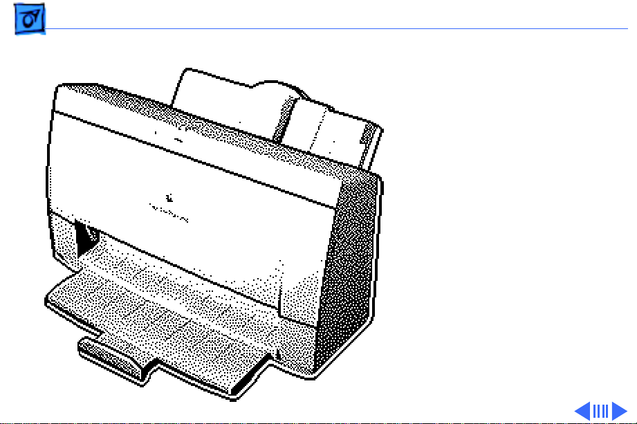
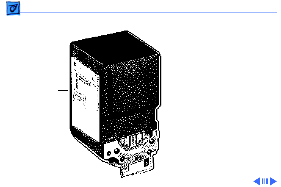
Overview
The Color StyleWriter 2400
is a desktop color bubblejet printer for personal use.
It has various features such
as high-speed printing
(3 pages per minute), high
print quality, printing on
plain or coated paper, and a
cut sheet feeder.
Page 4
Basics Overview - 2
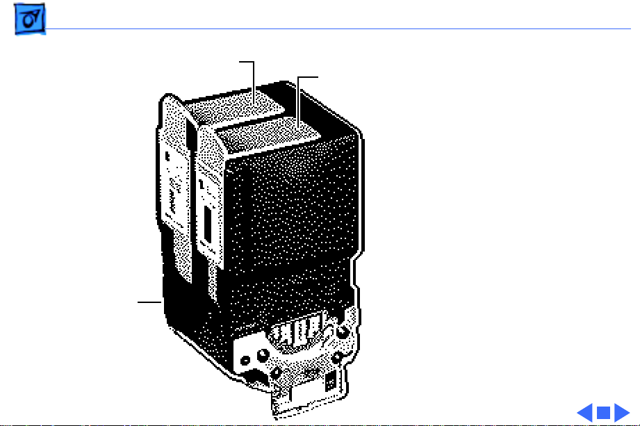
The Color StyleWriter 2400
can be configured with
either a four-color ink
cartridge or a highperformance black ink
cartridge. Both of these
cartridges can be easily
replaced.
Ink Tanks
Note:
The four-color
cartridge contains two ink
tanks that can be replaced
separately. One tank
contains black ink and the
other tank contains the
yellow, cyan, and magenta
inks. Each tank can be
replaced separately.
Page 5

Basics Overview - 3
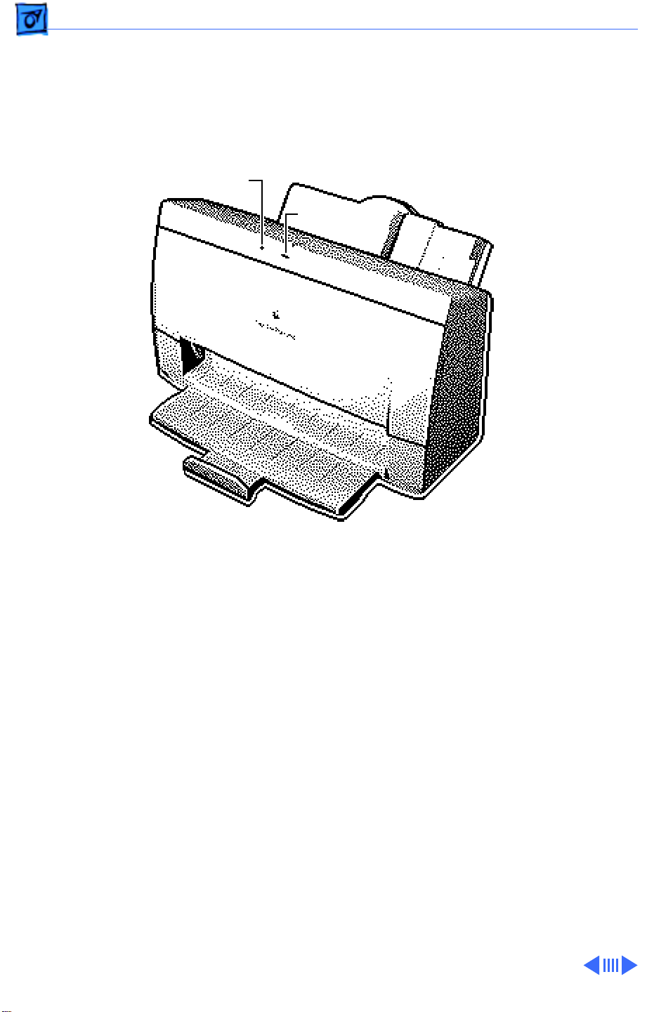
Error LED
Power LED
The Color StyleWriter 2400
has two LEDs that can aid in
troubleshooting the printer.
See the Troubleshooting
chapter for more
information.
Page 6
Basics Ink Cartridge Identification - 4
Ink Cartridge Identification
Ink Cartridge
Caution:
printer’s ink on your hands
or clothes. Although the ink
is water soluble, it contains
dyes that will stain.
Caution:
print heads from clogging,
do not touch or wipe them.
Do not get the
To prevent the
Page 7
Basics Ink Cartridge Identification - 5
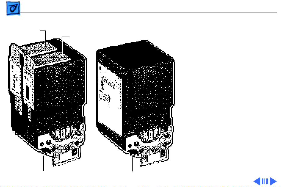
Note:
Four-Color
Ink Tank
Black-Only
Ink Tank
Two ink cartridges
come with the printer. One
cartridge is black ink only;
the other is a four-color ink
cartridge with two ink
tanks.
Four-Color
Ink Cartridge
Black-Only
Ink Cartridge
Page 8
Basics Ink Cartridge Identification - 6
High-Performance, Black-Only Ink Cartridge
The black ink cartridge
contains black ink only. The
Service part number for
Black–Only
Ink Cartridge
the black-only cartridge is
for service use only. To
order a replacement
cartridge for a customer,
use the finished goods part
number (M3240G/A).
Page 9
Basics Ink Cartridge Identification - 7
Four-Color
Ink Cartridge
Four-Color
Ink Tank
Black-Only
Ink Tank
Four-Color Ink Cartridge
The four-color ink cartridge
holds two ink tanks. One tank
contains black ink only, and
the other tank contains the
cyan, magenta, and yellow
inks.
The finished goods part
number for the black-only
tank is M3330G/A. The
finished goods part number
for the color tank is
M3329G/A).
Page 10

K
Service Source
Specifications
Color StyleWriter 2400
Page 11

Specifications Characteristics - 1
Characteristics
Print Methods
Throughput
Print Head
Serial bubble jet ink-on-demand
Up to three pages per minute with the high-performance black
ink cartridge
Up to 0.3 page per minute for color
Actual speed depends on the documents printed and the Macintosh
used
Four color cartridge: 136 nozzles (vertically-lined)
1 x 64 nozzles for black color
3 x 24 nozzles for yellow, magenta, cyan
Black cartridge: 128 nozzles (vertically-lined)
Page 12

Specifications Graphics - 2
Graphics
Resolution
360 x 360 dpi color (Rev A and Rev B)
720 x 360 dpi black & white (Rev B)
Page 13

Specifications Print Media - 3
Print Media
Paper
Envelopes
Transparencies
Back-Print Film
Plain paper, coated (recommended for color picture output)
Commercial number 10, monarch, and other sizes
Capacity: 15 envelopes
Coated transparencies, most ink jet transparencies
Capacity: 20 sheets
Letter, A4
For superior graphics and imaging results, premium paper and
back-print film are recommended
Page 14

Specifications Print Media - 4
Cut Sheets
LTR, LGL, A4
U.S. Letter (LTR): 8.5 x 11 in. (215.9 mm x 279.4 mm)
U.S. Legal (LGL): 8.5 x 14 in. (215.9 mm x 355.6 mm)
A4: 210 mm x 297 mm
Weight: 16-24 lbs. Capacity: 100 sheets (A4, LTR);
20 sheets coated paper
Page 15

Specifications Ink Cartridges - 5
Ink Cartridges
Type
Ink Color
Shelf Life
Print Head Cartridge Life
High-performance black ink cartridge with integrated ink tank
and print head
Four-color ink cartridge with two ink tanks (black only and
color—cyan, magenta, yellow) and integrated print head
Black
Four-color (Black, cyan, magenta, yellow)
6 months (installed in printer)
18 months (in original package)
Text: Approx. 900 pages (A4/LTR) high performance black only
Color: Approx. 1800 pages, with ink tank replacements
Page 16

Specifications Ink Cartridges - 6
Ink Tank Life
High performance black cartridge with integrated ink tank
900 pages at 7.5% coverage
Color ink tanks (Black or CMY)
100 pages at 7.5% coverage
Page 17

Specifications Environmental - 7
Environmental
Acoustic Noise Level
Temperature
Humidity
Approx. 45 dB (reference level)
59–86°F (15-30°C)
10–80% (no condensation)
Page 18

Specifications Electrical - 8
Electrical
Electrical Requirements
Power Consumption
120 V, 60 Hz, 1 A
220–240 V, 50 Hz, 0.5 A
45 W maximum
Page 19

Specifications Physical - 9
Physical
Dimensions
Weight
Height: 8.3 in. (211 mm)
Width: 14.4 in. (365 mm)
Depth: 8.4 in. (215 mm)
Approx. 7.9 lb. (3.6 kg)
Page 20

K
Service Source
Troubleshooting
Color StyleWriter 2400
Page 21

Troubleshooting General/ - 1
General
The Symptom Charts included in this chapter will help you
diagnose specific symptoms related to your product. Because cures
are listed on the charts in the order of most likely solution, try
the first cure first. Verify whether or not the product continues to
exhibit the symptom. If the symptom persists, try the next cure.
(Note: If you have replaced a module, reinstall the original module
before you proceed to the next cure.)
If you are not sure what the problem is, or if the Symptom Charts
do not resolve the problem, refer to the Flowchart for the product
family.
For additional assistance, contact Apple Technical Support.
Page 22
Troubleshooting Error Messages and LEDs/ - 2
Error Messages and LEDs
The Color StyleWriter 2400 has two LEDs that can aid in
troubleshooting the printer: error LED and power LED.
Error LED
Power LED
Page 23
Troubleshooting Error Messages and LEDs/ - 3
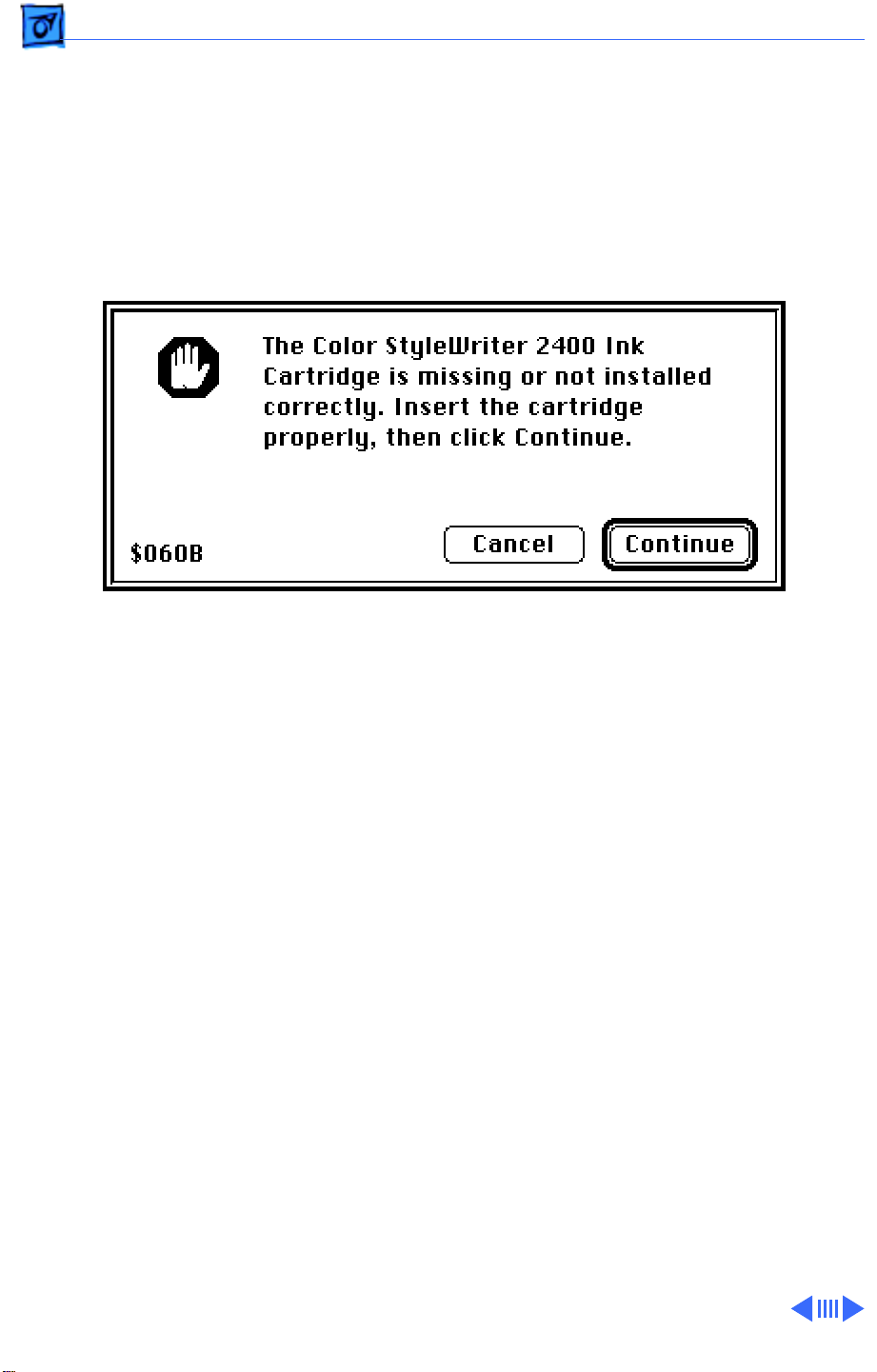
The printer software also gives error messages to pinpoint
errors.
Make sure the printer is hooked up to a Macintosh and that the
Color StyleWriter 2400 software is installed. See the Diagnostics
folder on the Service Source CD for the printer driver.
Page 24
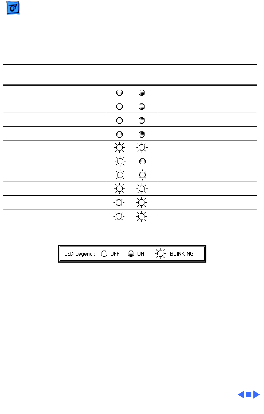
Troubleshooting Error Messages and LEDs/ - 4
The LEDs indicate the state of the printer or whether an error has occurred (e.g., carriage
control error, paper jam).
The following chart provides a summary of error codes and printer states. If an error is
indicated, check the chart, then go to “Error LEDs” in the Symptom Charts.
Software Error Message
(from printer driver)
Out of paper Paper pickup error
Paper jam Paper jam
Ink cartridge jam Carriage control error
Obstruction, clear and try again Cleaning error
Check connector and try again Temperature sensor error
Cartridge not installed properly Cartridge error
Check connectors and try again ROM/RAM error
Waste ink absorbers full Waste ink full error
Cartridge needs to be replaced Head temperature error
Cartridge needs to be replaced Head temperature sensor error
LEDs
Error Power
Symptom
(see Symptom Charts)
Page 25

Troubleshooting Symptom Charts/Operation - 5
Symptom Charts
Operation
No power 1 Check power cable connections.
2 Replace power cord.
3 Replace fuse.
4 Replace power supply.
Does not print 1 Turn on printer and restart computer.
2 Check interface cable connections.
3 Open Chooser and verify that correct printer driver and port
is selected.
4 Replace printer driver.
Page 26

Troubleshooting Symptom Charts/Operation - 6
Carriage unit does not
move to center when
front door is open, and
printer is on
Carriage unit moves
back and forth for five
minutes
Printer will not print
with LocalTalk option
installed
1 Make sure black latch on upper left corner of front door
engages button on logic board. See “Front Covers” topic in
Take Apart for additional information.
2 Replace logic board.
Print job was canceled during a purge. Turn printer off, then
back on.
1 Turn on printer and restart computer.
2 Check interface cable connections.
3 Open Chooser and verify that correct printer driver and port
are selected.
4 Replace printer driver.
5 Check that printer is functional by printing a test page.
6 Try printing directly through serial port.
7 Replace LocalTalk module.
Page 27

Troubleshooting Symptom Charts/Paper - 7
Paper
Paper sticks together 1 Remove excess sheets from paper tray.
2 Use only specified paper, envelopes, transparencies, and
backprint film.
3 Check that settings in Page Setup menu are correct.
4 Fan paper before putting it in paper tray.
Paper skews 1 Remove excess sheets from paper tray.
2 Use only specified paper, envelopes, transparencies, and
backprint film.
3 Stack paper flush against left side of paper tray and adjust
paper guide.
4 Check rollers on sheet feeder and eject roller. Clean or
replace if necessary.
Page 28

Troubleshooting Symptom Charts/Paper - 8
Paper jams during loading, before printing
Paper jams inside printer
Paper jams during output, after printing
Carefully remove paper by hand.
Carefully pull out paper in direction of paper output.
1 Carefully pull out paper in direction of paper output.
2 Check eject roller for obstructions or damage, and clean or
replace if necessary.
Page 29

Troubleshooting Symptom Charts/Print Quality - 9
Print Quality
Missing dots and/or white streaks
Blurring and/or smudging
1 Perform “Nozzle Check” and “Print Head Cleaning.” See
Additional Procedures chapter.
2 Make sure ink cartridges are set firmly.
3 Use only specified paper, envelopes, transparencies, and
backprint film.
4 Replace ink cartridge. See Additional Procedures chapter.
5 Replace logic board.
1 Use only specified paper, envelopes, transparencies, and
backprint film.
2 Perform “Print Head Cleaning.” See Additional Procedures
chapter.
3 Replace ink cartridge. See Additional Procedures chapter.
Page 30

Troubleshooting Symptom Charts/Print Quality - 10
Missing dots, followed by a blob of ink
Vertical lines are distorted/wavy
Poor image at bottom of page
Before printing, switch print quality to “Best” in printer driver.
Open and close blue lever next to cartridge to make sure cartridge
is seated properly.
Increase margin at bottom of page to at least 0.8 inch.
Page 31

Troubleshooting Symptom Charts/Error LEDs - 11
Error LEDs
Paper pickup error 1 Add paper.
2 Use only specified paper, envelopes, transparencies, and
backprint film.
3 Check that settings in Page Setup menu are correct.
4 Fan paper before putting it in paper tray.
Paper jam Check eject roller for obstructions or damage, and clean or
replace if necessary.
Carriage control error
Cleaning error Check eject roller for obstructions or damage, and clean or
Check eject roller for obstructions or damage, and clean or
replace if necessary.
replace if necessary.
Page 32

Troubleshooting Symptom Charts/Error LEDs - 12
Temperature sensor error
Cartridge error 1 Make sure ink cartridges are set firmly.
ROM/RAM error 1 Check cable connections.
Waste ink full error Replace ink absorbers.
Head temperature error
Head temperature sensor error
1 Check cable connections.
2 Replace logic board.
2 Replace ink cartridge.
3 Replace carriage unit.
2 Reinstall printer software.
3 Replace logic board.
Replace ink cartridge.
Replace ink cartridge.
Page 33

K
Service Source
T ak e Apart
Color StyleWriter 2400
Page 34

Take Apart Front Covers - 1
Front Covers
Front
Case
Front
Door
Output Tray
Extension
Output Tray
No preliminary steps are
required before you begin
this procedure.
Note:
The “Front Covers”
topic includes the front
door, front case, output
tray, and output tray
extension.
Page 35

Take Apart Front Covers - 2
Front Door
Note:
The front door is held
in place by two arms that
Front
Case
function as hinges. Plastic
tabs at the end of the arms
fit into knobs on the inside of
the upper case.
Arm Tab
Front
Door
1 Swing open the front
door.
2 Press the end of each
arm inward and free the
arm tabs from the front
case.
3 Lift off the front door.
Ê
Page 36

Take Apart Front Covers - 3
Front Door
Small Gears
and Springs
Replacement Note:
The
small gears and springs in
the front door fall out of
position if a paper jam is
forcibly removed from the
printer. These gears and
springs are not available as
service replacement parts.
See the “Small Gear
Replacement” topic in
Additional Procedures.
Page 37

Take Apart Front Covers - 4
Front Case
1 Lift the center of the
case to release the center
latch on the front case.
2 Release the right side
Center
Latch
Right Side
Latch
Front
Case
latch and pull the front
case forward a short
distance.
3 Repeat for the left side
latch and remove the
case.
Page 38

Take Apart Front Covers - 5
Latch
Front
Case
Latch
On/Off
Button
Replacement Note:
Make
sure the latches on the front
case engage the buttons on
the logic board.
Page 39

Take Apart Front Covers - 6
Output T ray
1 Pull out the output tray
until the two tabs rest
against the stops on the
bottom case.
2 Press down and remove
the tray.
Tab
Output Tray
Page 40

Take Apart Front Covers - 7
Output T ray Extension
1 Pull out the tray
extension until the two
tabs rest against the
stops.
2 Press down and remove
the tray extension.
Output Tray Extension
Page 41

Take Apart Eject Roller - 8
Eject Roller
Before you begin, remove
the covers (see “Front
Door”).
Eject Roller
Page 42

Take Apart Eject Roller - 9
Grasp one end of the roller,
press the bracket to the
side, and remove the eject
roller from the printer.
Eject Roller
Page 43

Take Apart Rear Covers - 10
Rear Covers
Rear Covers
Before you begin, remove
the following:
• Front covers
• LocalTalk module
(if present)
Note:
For information on
removing the LocalTalk
module, see the “LocalTalk
Module” topic in the
Upgrades chapter.
Note:
The “Rear Covers”
topic includes the rear case,
interface cover, and logic
board cover.
Page 44

Take Apart Rear Covers - 11
Latch
Plastic Lip
Rear Case
1 Pull out the bottom of
the rear case slightly to
clear the plastic lip.
Rear Case
2 Using a flat-blade
screwdriver, release the
latch and lift up the rear
case.
3 Repeat for the other side
of the case.
Page 45

Take Apart Rear Covers - 12
Rear Covers
4 Release the three
latches on the top of the
printer.
Page 46

Take Apart Rear Covers - 13
5 Lift up and release the
rear case from the two
Rear Case
tabs on the back of the
printer.
6 Remove the rear case.
Tab
Tab
Page 47

Take Apart Rear Covers - 14
Interface Cover
1 Using a small flat-blade
Interface
Cover
Mounting Tab
screwdriver, release the
mounting tab and remove
the interface cover from
the rear case.
Page 48

Take Apart Rear Covers - 15
Logic Board Cover
Front Latch
1 Press in the front latch
and release the side
latch.
2 Pull back and remove the
logic board cover from
the printer.
Side
Latch
Page 49

Take Apart Cut Sheet Feeder - 16
Cut Sheet Feeder
Cut Sheet Feeder
Before you begin, remove
the following:
• Front covers
• Rear covers
Caution:
precautions in Bulletins/
Safety.
Review the ESD
Page 50

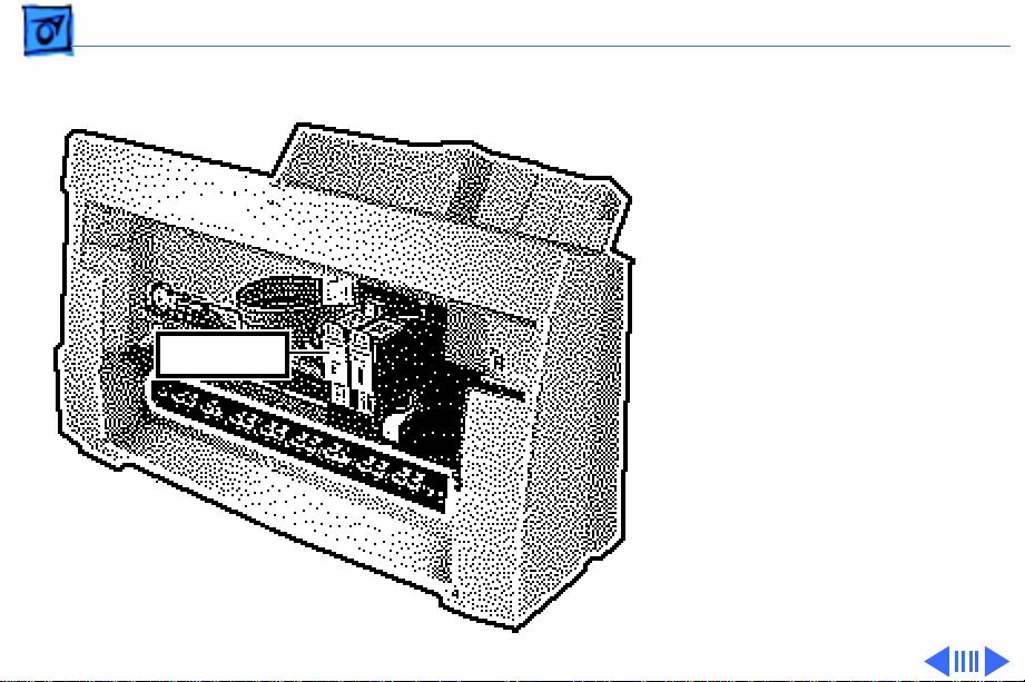
Take Apart Cut Sheet Feeder - 17
1 Disconnect connectors
CNV and CNLF from the
logic board.
CNV
Connector
CNLF
Connector
Page 51

Take Apart Cut Sheet Feeder - 18
2 Remove the connector
wires from the slot on
the cut sheet feeder.
Cut Sheet Feeder
Slot
Connector Wires
Page 52

Take Apart Cut Sheet Feeder - 19
3
Note:
Make sure the
Cut Sheet Feeder
screws do not fall into
the bottom cover.
Using a Phillips
screwdriver, remove
the two screws that
secure the cut sheet
feeder to the printer.
4 Press in the latch and
remove the cut sheet
feeder.
Page 53

Take Apart Cut Sheet Feeder - 20
Alignment
Pin
Alignment Pin
Replacement Note:
Make
sure the alignment pins on
the cut sheet feeder are
aligned with the printer
frame.
Page 54

Take Apart Paper Support - 21
Paper Support
Paper Support
Before you begin, remove
the following:
• Front covers
• Rear covers
• Cut sheet feeder
Caution:
precautions in Bulletins/
Safety.
Review the ESD
Page 55

Take Apart Paper Support - 22
1 Pull out the paper
support until it rests
Paper Support
against the stops.
2 Push the support
forward and disconnect
the latches.
Latches
3 Slide out the paper
support.
Page 56

Take Apart Pickup Roller - 23
Pickup Roller
Cut Sheet Feeder
Pickup Roller
Before you begin, remove
the following:
• Front covers
• Rear covers
• Cut sheet feeder
Caution:
precautions in Bulletins/
Safety.
Review the ESD
Page 57

Take Apart Pickup Roller - 24
Cut Sheet Feeder
Caution:
When the roller
1
is removed, the feeder
gear is loose. Remove the
roller slowly so that the
gear will not fly off.
Press in the two latches
on the pickup roller and
push out the roller.
2 Remove the feeder gear
from the cut sheet
feeder.
Feeder Gear
Latches
Page 58

Take Apart Pickup Roller - 25
3 Lift up one end of the
roller and remove the
other end from the
mounting hole.
Pickup Roller
Cut Sheet Feeder
4 Remove the pickup
roller from the cut sheet
feeder.
Page 59

Take Apart Pickup Roller - 26
Notch
Notch
Upper Gear
Feeder Gear
Replacement Note:
Align the
notch on the upper gear with
the upper line on the cut
sheet feeder. Align the notch
on the feeder gear with the
lower line on the cut sheet
feeder.
Page 60

Take Apart Logic Board - 27
Logic Board
Before you begin, remove
the following:
Logic Board
• Front covers
• Rear covers
• Cut sheet feeder
Caution:
precautions in Bulletins/
Safety.
Review the ESD
Page 61

Take Apart Logic Board - 28
Note:
Information on the
amount of ink absorbed by
the ink absorbers is stored
on the logic board EEPROM.
When replacing the logic
Upper Ink
Absorber
board, check the ink
absorbers. If the upper ink
absorber has ink in it,
Lower Ink
Absorber
replace it. Always replace
the lower ink absorber.
Page 62

Take Apart Logic Board - 29
If the ink absorbers have
been used for two weeks or
less, or if fewer than 50
pages have been printed, it
is not necessary to replace
Upper Ink
Absorber
the ink absorbers when
replacing the logic board.
Lower Ink
Absorber
See “EEPROM Reset” in
Additional Procedures for
more information.
Page 63

Take Apart Logic Board - 30
CNCR
CNH
1 Disconnect the following
connectors from the
logic board:
• CNCR
• CNH
• CNLF
• CNV
CNV
CNLF
Page 64

Take Apart Logic Board - 31
2 Using a Phillips
screwdriver, remove
the three mounting
screws.
Logic Board
3 Remove the logic board
from the printer.
Page 65

Take Apart Power Supply - 32
Power Supply
Before you begin, remove
the following:
• Front covers
• Rear covers
• Cut sheet feeder
Power Supply
Caution:
precautions in Bulletins/
Safety.
Review the ESD
Page 66

Take Apart Power Supply - 33
1 Disconnect connector
CNV from the logic
board.
CNV
Page 67

Take Apart Power Supply - 34
2 Using a Phillips
screwdriver, loosen the
two mounting screws and
remove the power
supply from the printer.
Power Supply
Page 68

Take Apart Power Supply - 35
Power Supply
Tab
Tab
Replacement Note:
Make
sure the mounting tabs on
the bottom of the power
supply are seated properly
on the bottom case.
Page 69

Take Apart Fuse - 36
Fuse
Before you begin, remove
the following:
• Front covers
• Rear covers
• Cut sheet feeder
Fuse
Caution:
precautions in Bulletins/
Safety.
Review the ESD
Page 70

Take Apart Fuse - 37
1 Remove the fuse cover
and replace the fuse.
Fuse Cover
Page 71

Take Apart Carriage Unit - 38
Carriage Unit
Carriage Unit
Before you begin, remove
the following:
• Front covers
• Rear covers
• Cut sheet feeder
Caution:
precautions in Bulletins/
Safety.
Caution:
print nozzles from clogging,
do not touch or wipe them.
Review the ESD
To prevent the
Page 72

Take Apart Carriage Unit - 39
Screw
Carriage Guide
Screw
Caution:
Do not remove or
loosen the two screws on top
of the carriage guide.
Loosening or removing
these screws will cause the
carriage to go out of
alignment.
Page 73

Take Apart Carriage Unit - 40
1 Turn the printer so that
the power supply faces
you.
Power Supply
Page 74

Take Apart Carriage Unit - 41
2 Disconnect connector
CNH from the logic
board.
CNH
Page 75

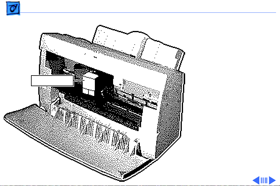
Take Apart Carriage Unit - 42
3 Turn the printer so that
the carriage unit faces
Carriage Unit
you.
Page 76

Take Apart Carriage Unit - 43
4 Remove the plastic
Cable Holder
ribbon cable and cable
holder from the printer.
Ribbon Cable
Page 77

Take Apart Carriage Unit - 44
Ribbon
Cable Holder
Carriage Unit
Tab
Ribbon Cable
Holes
Replacement Note: Make
sure the ribbon cable holes
are mounted on the two tabs
on the inside of the ribbon
cable holder and the small
tab is in the slot on the
carriage unit.
Page 78

Take Apart Carriage Unit - 45
5 Press in the two latches.
6 Push up and remove the
carriage release clip
Carriage Release Clip
from the printer.
Page 79

Take Apart Carriage Unit - 46
7 Using a Phillips
screwdriver, remove
the mounting screw from
the carriage shaft.
Carriage
Shaft
Mounting
Screw
Page 80

Take Apart Carriage Unit - 47
8 Carefully remove the
shaft clip from the
carriage shaft.
Shaft
Clip
Carriage
Shaft
Page 81

Take Apart Carriage Unit - 48
9 Using a flat-blade
screwdriver, carefully
Carriage
Belt
press in the carriage
belt tensioner and
disconnect the carriage
belt.
Carriage
Belt
Tensioner
Page 82

Take Apart Carriage Unit - 49
10 Hold the carriage unit
and slide out the carriage
Carriage Unit
shaft.
11 Remove the carriage unit
from the printer.
Replacement Note: Make
sure the carriage unit is
reinstalled properly in
the printer.
Page 83

Take Apart Carriage Ribbon Cable - 50
Carriage Ribbon
Carriage Ribbon Cable
Cable
Before you begin, remove
the following:
• Front covers
• Rear covers
• Cut sheet feeder
• Ink cartridge
• Carriage unit
Caution: Review the ESD
precautions in Bulletins/
Safety.
Page 84

Take Apart Carriage Ribbon Cable - 51
1 Caution: Carefully
remove the sensor to
avoid damaging the
carriage ribbon cable.
Carriage Ribbon Cable
Remove the sensor from
the carriage unit.
Sensor
Page 85

Take Apart Carriage Ribbon Cable - 52
2 Press in the five latches
and remove the ribbon
cable guide.
Ribbon Cable
Guide
Page 86

Take Apart Carriage Ribbon Cable - 53
Ribbon
Cable Holder
Carriage Unit
Tab
Ribbon Cable
Holes
3 Remove the ribbon cable
from the carriage unit.
Replacement Note: Make
sure the ribbon cable
holes are mounted on the
two tabs on the inside of
the ribbon cable holder
and the small tab is in
the slot on the carriage
unit.
Page 87

Take Apart Carriage Belt - 54
Carriage Belt
Carriage Belt
Before you begin, remove
the following:
• Front covers
• Rear covers
• Cut sheet feeder
• Ink cartridge
• Carriage unit
Caution: Review the ESD
precautions in Bulletins/
Safety.
Page 88

Take Apart Carriage Belt - 55
Carefully remove the
carriage belt from the
carriage unit.
Carriage Unit
Carriage
Belt
Page 89

Take Apart Carriage Belt Tensioner - 56
Carriage Belt Tensioner
Before you begin, remove
the following:
Carriage
Belt
Tensioner
• Front covers
• Rear covers
• Cut sheet feeder
Caution: Review the ESD
precautions in Bulletins/
Safety.
Page 90

Take Apart Carriage Belt Tensioner - 57
1 Using a flat-blade
screwdriver, carefully
Carriage
Belt
press in the carriage
belt tensioner and
disconnect the carriage
belt.
Carriage
Belt
Tensioner
Page 91

Take Apart Carriage Belt Tensioner - 58
2 Slide out the carriage
belt tensioner from the
printer.
Carriage
Belt
Tensioner
Page 92

Take Apart Printer Frame - 59
Printer Frame
Printer Frame
Before you begin, remove
the following:
• Front covers
• Rear covers
• Cut sheet feeder
• Power supply
Caution: Review the ESD
precautions in Bulletins/
Safety.
Page 93

Take Apart Printer Frame - 60
Note: The printer frame is
not a replaceable part.
Printer Frame
Remove the frame to access
the purge unit, paper feed
motor, ink absorbers, and
bottom case.
1 Release the right latch
and lift up the printer
frame.
Right
Latch
Page 94

Take Apart Printer Frame - 61
2 Release the left latch
Printer
Frame
and remove the printer
frame from the bottom
cover.
Left
Latch
Page 95

Take Apart Printer Frame - 62
Replacement Note: Make
sure the bottom case
Printer Frame
circular tabs fit into the
proper position in the
printer frame.
Circular
Tab
Circular
Bottom Case
Tabs
Page 96

Take Apart Paper Feed Motor - 63
Paper Feed Motor
Before you begin, remove
the following:
• Front covers
• Rear covers
• Cut sheet feeder
• Power supply
• Printer frame
Caution: Review the ESD
precautions in Bulletins/
Safety.
Paper Feed Motor
Page 97

Take Apart Paper Feed Motor - 64
1 Disconnect connector
Logic Board
CNLF
Paper Feed Motor
CNLF from the logic
board.
Page 98

Take Apart Paper Feed Motor - 65
2 Move the platen bracket
Platen Bracket
away from the mounting
screw.
Page 99

Take Apart Paper Feed Motor - 66
3 Note: Carefully remove
the paper feed motor to
avoid losing the gear.
Using a Phillips
screwdriver, remove
the two mounting
screws.
4 Remove the paper feed
motor from the printer.
Page 100

Take Apart Paper Feed Motor - 67
5 Remove the gear from
the paper feed motor.
Gear
Paper
Feed
Motor
 Loading...