

Page 1

TM
MasterSwitch 100V
AP9210
User
Guide
j
Page 2

2 2
MasterSwitch 100V – User Guide
MasterSwitch – User Guide
SOFTWARE LIMITED WARRANTY
WITH RESPECT TO THE PHYSICAL DISKETTE AND PHYSICAL MATERIAL ENCLOSED WITHIN, APC WARRANTS THE SAME TO BE FREE OF DEFECTS IN MATERIALS AND
WORKMANSHIP
MATERIAL
SERVICE
REPLACEMENT
OR
OTHER SIMILAR CLAIMS.
FOR A PERIOD OF 90 DAYS FROM THE DATE OF PURCHASE. IN THE EVENT OF NOTIFICATION WITHIN THE WARRANTY PERIOD OF DEFECTS IN
OR WORKMANSHIP, APC WILL REPLACE THE DEFECTIVE DISKETTE OR MATERIAL. IF YOU NEED TO RETURN A PRODUCT, CALL THE APC CUSTOMER
DEPARTMENT TO OBTAIN A RETURN MATERIAL AUTHORIZATION (RMA) NUMBER. THE REMEDY FOR BREACH OF THIS WARRANTY SHALL BE LIMITED TO
AND SHALL NOT ENCOMPASS ANY OTHER DAMAGES, INCLUDING BUT NOT LIMITED TO LOSS OF PROFIT, AND SPECIAL, INCIDENTAL, CONSEQUENTIAL
APC SPECIFICALLY DISCLAIMS ALL OTHER WARRANTIES, EXPRESSED OR IMPLIED, INCLUDING BUT NOT LIMITED TO IMPLIED WARRANTIES OF MERCHANTABILITY
AND
FITNESS FOR A PARTICULAR PURPOSE WITH RESPECT TO THE SOFTWARE, INCLUDING THE DISKETTE, DOCUMENTATION, AND CABLES. IN NO EVENT SHALL APC
BE LIABLE FOR ANY LOSS OF PROFIT OR OTHER COMMERCIAL DAMAGE, INCLUDING BUT NOT LIMITED TO SPECIAL, INCIDENTAL, CONSEQUENTIAL OR OTHER
DAMAGES
.
LICENSES & TRADEMARKS
The following are product and corporate names used in this guide that are trademarks or registered trademarks of American Power Conversion
Corporation: APC™, Back-UPS®, Back-UPS® Pro, MasterSwitch, Matrix-UPS™, Measure-UPS™, NetShelter™, PowerChute®,
PowerChute® plus, PowerNet™, SNMP Adapter™ , Smart-UPS and Smart-UPS® v/s™.
All other trademarks, product and corporate names are the property of their respective owners and used here for informational purposes only.
© Copyright American Power Conversion Corporation, 1998. All Rights Reserved. Reproduction in whole or in part without permission is
prohibited.
APC Corporate APC Europe APC Ireland APC Japan
132 Fairgrounds Road Omodaka Bldg 5F 1-9-7 Shibaura
P.O. Box 278 4 Rue St Claire Deville Ballybritt Industrial Estates Minato-ku
West Kingston, RI 02892 Lognes F-77185 Galway Tokyo, 105
United States of America France Ireland Japan
Toll Free: 800 800 4APC Toll Free: 0 800 09 24 07 Toll Free: 1 800 702000 Free Dial: 0120-80-60-90
Tel: 401 789 5735 Tel: 01 64 62 59 00 Tel: 353 91 702000 Tel: (81) (03) 3798-3888
Fax: 401 789 3180 Fax: 33 1 60 17 80 29 Fax: 353 91 756909 Fax: (81) (03) 3798-3880
990-0207 Rev 1 5/98
Page 3

3
MasterSwitch 100V – User Guide
Contents
About This Guide 6
Who Should Read This Guide ..........................................................................................................................6
Associated Documents.....................................................................................................................................6
Registering Your Product ..................................................................................................................................6
Abbreviations ....................................................................................................................................................6
The APC Web Site............................................................................................................................................6
APC Product Information and Technical Support..............................................................................................7
Chapter 1:
Introduction 8
Overview...........................................................................................................................................................8
Front Panel ........................................................................................................................................................9
Chapter 2:
Initial
Setup 10
3
Chapter 3:
Logging On 11
Types of Access ..............................................................................................................................................11
Login Control ..................................................................................................................................................11
Chapter 4:
Configuring the
MasterSwitch 12
Functions ........................................................................................................................................................12
Master Power On Delay ..................................................................................................................................13
Outlet Power On Delay ................................................................................................................................... 13
Reboot Duration..............................................................................................................................................14
MasterSwitch Device Name............................................................................................................................14
Outlet Device Name........................................................................................................................................14
URL Links ....................................................................................................................................................... 14
Chapter 5:
Controlling the
MasterSwitch 15
Overview.........................................................................................................................................................15
Master Power Control .....................................................................................................................................15
Outlet Power Control.......................................................................................................................................15
Page 4

4 4
MasterSwitch 100V – User Guide
Chapter 6:
Using the
Console Program 16
Functions ........................................................................................................................................................16
Accessing the Console Program ....................................................................................................................17
Via the Serial Port 17
Via telnet 17
The Main Menu...............................................................................................................................................17
Outlet Submenu..............................................................................................................................................18
Auto Power On 20
Master Outlet Configuration and Control 20
Network Submenu ..........................................................................................................................................21
TCP/IP Submenu 21
Telnet Submenu 22
HTTP Submenu 22
SNMP Submenu 23
SNMP Summary Page 23
SNMP Access Control Submenu 24
MasterSwitch Submenu..................................................................................................................................24
Password Submenu 24
Tools Submenu 25
Control Console Submenu 25
About Submenu 26
Chapter 7:
Using
SNMP 27
Functions ........................................................................................................................................................27
apcmgmt OIDs................................................................................................................................................ 28
Management Control (mcontrol) OIDs 28
Management Configuration (mconfig) OIDs 28
MasterSwitchV1 OIDs.....................................................................................................................................29
Identification (sPDUIdent) OIDs 29
Master Control (sPDUMasterControl) OIDs 29
Master Configuration (sPDUMasterConfig) OIDs 29
Outlet Control (sPDUOutletControl) OIDs 30
Outlet Configuration (sPDUOutletConfig) OIDs 30
Traps ...............................................................................................................................................................31
MasterSwitch-MIB T raps 31
MIB-II Traps 31
Chapter 8:
Using Embedded
Web Contr o l 32
Accessing Web Control................................................................................................................................... 32
Functions ........................................................................................................................................................32
Page 5

5
MasterSwitch 100V – User Guide
Chapter 9:
User-Interface
Components 34
Reset Button ...................................................................................................................................................34
Outlet LEDs ....................................................................................................................................................34
Network LEDs .................................................................................................................................................34
Index 35
5
Page 6

6 6
MasterSwitch 100V – User Guide
About This Guide
This user guide contains information about configuring and using the American Power Conversion (APC)
MasterSwitch™, a stand-alone power distribution unit (
Who Should Read This Guide
This guide is for anyone responsible for using the MasterSwitch to control power.
Associated Documents
This guide explains how to use the MasterSwitch only. Refer to your APC UPS Owners Manual for
operational information for your specific
came with the MasterSwitch for information on how to install the MasterSwitch.
UPS systems. Refer to the MasterSwitch Installation Guide that
PDU).
Registering Y our Product
Please fill out and return the enclosed warranty card. This card not only provides us with valuable, welcomed
feedback on how we can refine our products to better serve your needs, but it also enables us to notify you
about important product updates and changes.
Abbreviations
APC refers to American Power Conversion; EEPROM refers to Electrical Erasable Programmable Read Only
Memory;
tification;
IP refers to Internet Protocol; MIB refers to management information base; OID refers to object iden-
SNMP refers to simple network management protocol; UPS refers to Uninterruptible Power Supply.
The APC Web Site
For more information on this or any other APC product, visit the APC Web site at http://www.apc.co.jp/. APC
is continuously updating the information you obtain from its Web site, including its product documentation.
Page 7

7
MasterSwitch 100V – User Guide
APC Product Information and Technical Support
Call 0120-80-6090 or 813-5434 2021 to directly access APC’s product information database and request to
have the latest
APC product information faxed directly to you.
7
If you have any questions concerning the MasterSwitch, or concerning any other
the technical support center nearest you.
APC T echnical Support is provided at no charge. APC T echnical
Support teams can be accessed in any of the following ways:
Worldwide Web Site: http://www.apc.co.jp/
™
CompuServe
: GO APCSUPPORT
Internet (US): apctech@apcc.com
Internet (Europe): apceurtsg@apcc.com
Telephone Access:
Japan Free Dial: 0120-80-6090
Phone: +813-5434 2021
Fax: +613-5434 2022
Worldwide Headquarters Toll Free: (800)800-4APC
European Headquarters Phone: (33)(1)64 62 59 00
Fax: (33)(1)60 17 80 29
European Tech Support Phone: (353)91 702020
Fax: (353)91 755275
US and Canada Phone: (401)789-5735
Fax: (401)789-3180
Austria T oll Free: 0660 6480
Belgium Toll Free: 0800 15063
Czech Republic Toll Free: 0800 102063
Denmark Toll Free: 800 18 153
Finland Toll Free: 9800 13 374
France Toll Free: 0 800 906 483
Paris: 01 64 62 59 00
Germany Toll Free: 0130 818907
Holland Toll Free: 0800 0224655
Hungary Toll Free: 00800 12221
Ireland Toll Free: 1 800 702000 x 2045
Israel Toll Free: 177 353 2206
Italy Toll Free: 1678 74731
Luxembourg T oll Free: 0800 2091
Norway T oll Free: 800 11 632
Poland Toll Free: 00800 353 1202
Portugal Toll Free: 050 553182
Russia Phone: +7095 916 7166
South Africa Toll Free: 0800 994206
Spain Toll Free: 900 95 35 33
Sweden Toll Free: 020 795 419
Switzerland Toll Free: 0800 556 177
Turkey Toll Free: 0800 35390275
United Kingdom Toll Free: 0800 132990
APC product, please contact
Page 8

8 8
MasterSwitch 100V – User Guide
Chapter 1: Introduction
The APC MasterSwitch is a network-manageable power control unit (PCU) that allows you complete,
independent control of power to eight relay-controlled outlets. This control is programmable using any of the
following strategies:
nWeb-based control. The MasterSwitch features embedded Web management.
nSimple network management protocol (SNMP) control. The MasterSwitch comes with its own
™
PowerNet
management station to use
and MIB-II compliant MIB (APC MasterSwitch-MIB) to allow a remote network
SNMP to program control of the MasterSwitch and its eight outlets.
nConsole control. The MasterSwitch has a built-in serial port which allows you to connect a terminal
(or terminal emulator) directly to the MasterSwitch to use its internal console program to configure
power control.
nTelnet support. The MasterSwitch provides a telnet interface that permits remote access to the
terminal console program.
Note: MasterSwitch Web control functions and the MasterSwitch console program
are protected by a user name/password pair. The default user name is apc, in
lower case. The default password is apc.
Note: This guide focuses on providing information on how to use SNMP, telnet, or a terminal
to program the MasterSwitch. Information on how to program the MasterSwitch
its embedded Web management feature is provided by a separate on-line help
application that focuses solely on how to use the Web management capabilities.
Overview
The MasterSwitch is a network manageable power control unit (PCU) that:
using
nConnects a single 100VAC, 50/60Hz input to eight 100VAC, 50/60Hz outlets. The overall output of
these outlets is limited to
circuit breaker and inlet connector are all located on the MasterSwitch rear panel.
15 amps and protected by a resettable 15-amp circuit breaker. The outlets,
nAllows programmable control of the MasterSwitch, such as defining a delay between power coming
on for the MasterSwitch and master power going to the outlets, or turning on, off or rebooting all
outlets at one time.
nAllows independent, programmable control over each of its eight outlets, such as defining when an
outlet will provide power after master power is provided, or turning on, off or rebooting each outlet
individually without affecting the output from any other outlet.
nIs designed to mount in an APC NetShelter
Note: The MasterSwitch does not provide power protection. Therefore, APC does not
recommend plugging the MasterSwitch directly into any unprotected power
source, such as a wall outlet.
™
and connect to a UPS for its input power.
Page 9
9
MasterSwitch 100V – User Guide
9
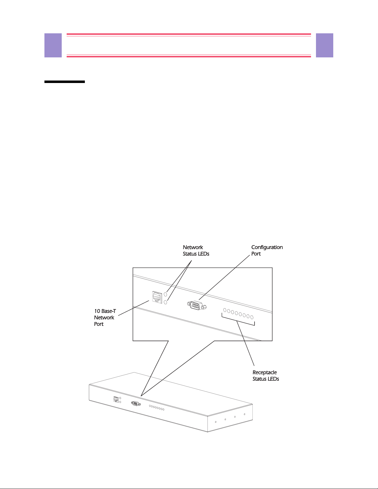
Front Panel
The primary feature of the MasterSwitch is the programmable control of eight power outlets using embedded
W eb-based control,
connectors provide for the physical link for programming:
SNMP control, or the console program via telnet or the onboard serial port. Two
n A built-in serial port, which connects a terminal (or terminal emulator) to access the console program.
n A built-in 10Base-T network connector, which connects the MasterSwitch to an Ethernet LAN to
allow using the embedded Web control, telnet, or
MasterSwitch must connect to an Ethernet
As shown in Figure 1, both of these connectors are located on the front panel. Figure 1 also identifies the
following:
SNMP to configure the MasterSwitch. The
LAN to use telnet, SNMP or embedded Web control.
n Eight receptacle LEDs. When an outlet is on, the corresponding LED is lit.
n Two network status LEDs— Status and Link - TX/RX. LEDs provide visual indications about the
Ethernet LAN connection.
n A reset button, which reinitializes the MasterSwitch without affecting its outlet power.
Figure 1: MasterSwitc h Front Panel
Page 10

10 10
MasterSwitch 100V – User Guide
Chapter 2: Initial Setup
The MasterSwitch must have its network settings defined for it to function properly for SNMP, telnet, or
embedded Web control of its output power:
n Its IP address
n The IP address of the default gateway
n The subnet mask
n HTTP and telnet port number (for Web-based or telnet control)
How the MasterSwitch initially gets these values depends on whether or not you will be using a
BOOTP server:
n The MasterSwitch comes with the Bootstrap Protocol (BOOTP) setting enabled. This allows you to
configure a
1) Identify the
to the MasterSwitch side panel.
2) Refer to your
the MasterSwitch network values.
BOOTP server to provide the needed subnet mask and IP values:
MAC address of the MasterSwitch. This address is provided on a label that is attached
BOOTP server documentation for information on how to use that server to configure
n If you will not be using a BOOTP server you must use a terminal to access the MasterSwitch, and use
its console program. T o access the console program:
1) Connect one end of the cable that comes with the MasterSwitch to the connector labeled “Serial
Port” at the front of the MasterSwitch.
2) Connect the cable to the serial port of the terminal (or terminal emulator).
3) Set the terminal serial port for 19200 baud, 8 data bits, no parity , 1 stop bit and press <Enter>.
4) When the
5) When the Password: prompt appears, enter the case-sensitive, default password (apc).
6) Once the main configuration menu appears:
User Name: prompt appears, enter the case-sensitive, default user name (apc).
r Use the Passwords option under the MasterSwitch submenu to change the login
password.
Note: The console, telnet, and W eb control share the same password. When you
change the password using the console, telnet, or W eb control, you change the
password for all three control functions.
r Use the TCP/IP option under the Network submenu to disable BOOTP and define:
a) The IP address for the MasterSwitch.
b) The IP address for the default gateway.
c) The subnet mask value.
r Use the Logout option to exit the console program, or use any of the other main
configuration menu options to further define the MasterSwitch operation before you log out.
Note: See Chapter 6 for more information on how to use the console program.
Page 11

11
MasterSwitch 100V – User Guide
Chapter 3: Logging On
This chapter describes how Web control, console program, and SNMP access is controlled so that only one
control option (Web control, console or
Note: References throughout this document to the console program apply to telnet sessions
and serial communications sessions, which provide identical terminal-style menus.
Types of Access
The MasterSwitch allows simultaneous read-only access from Web control, console session (via the serial
cable or telnet) and
sessions or
new configuration and control values at a time.
SNMP access to configure and control the MasterSwitch, but only one of these can be used to write
SNMP. It does not allow simultaneous write access. You can use Web control, console
SNMP) can be used at a time for write activity.
11
W eb control and terminal console sessions have protected access using a shared user name/ password pair (the
default password is apc, all lower case).
SNMP access, and that the NMS uses the proper community name for the defined type of SNMP access.
SNMP access simply requires that the NMS be defined as having
Login Contro l
Terminal console and telnet sessions have the highest access priority. If someone has logged on to the
MasterSwitch using either of these interfaces, Web control access is disabled, and
GETs) only.
reads (
The embedded W eb control has the second highest access priority. If someone has logged on to the
MasterSwitch using the embedded W eb control, then
someone logs on to the MasterSwitch using the terminal console or telnet while someone is logged on to the
W eb control, the Web control user is automatically logged off.
SNMP write (SETs) access to the MasterSwitch can only occur when no one is logged on to the MasterSwitch
using either W eb control or the terminal console.
Note: SNMP access is controlled by MasterSwitch-MIB OIDs that define what NMSs can
access the MasterSwitch, the access they have (read/write or just read) and what
community name must be used for that access.
SNMP access is limited to reads (GETs) only. However , if
SNMP access is limited to
Page 12

12 12
MasterSwitch 100V – User Guide
Chapter 4: Configuring the MasterSwitch
This chapter describes how to use SNMP, embedded Web control or the console program to configure the
MasterSwitch and its eight, individually-manageable power outlets.
Note: Most configuration functions can be performed using Web, SNMP or console control.
However, some functions are unique to a given control method(s). The descriptions
in this chapter identify which methods you can use (Web,
for each described configuration function.
Functions
The MasterSwitch allows you to use SNMP, embedded Web or the terminal console program to configure
operational parameters or other values important to using the MasterSwitch:
SNMP or console control)
n You can use Web, SNMP or console configuration commands to:
r Define a master power on delay value that affects all outlets equally.
r Define a reboot duration value that affects all outlets equally.
r Define a MasterSwitch device name.
r Define outlet device names.
r Define individual outlet power on values.
r Define SNMP access control for up to four network management stations (NMSs).
r Define up to four SNMP trap receivers.
Note: See Chapter 7: Using SNMP for more information on SNMP access control and
trap receivers.
r Reinitialize the MasterSwitch without affecting its outlet power .
n You can use embedded Web control, or the console program (but not SNMP), to enable or disable
BOOTP, or to define the MasterSwitch IP address, the default gateway IP address or the subnet mask
network configuration values needed by the MasterSwitch to communicate over the network.
Note: The console has an option (HTTP Net Config) in the Network submenu that
enables or disables the use of Web control to change the network configuration values.
See Chapter 2 for information on how to use the console program to define the needed
network values; See the help application provided with the embedded Web control for
information on how to use the Web control feature.
n You can use embedded Web control, only, to define URL link values for the MasterSwitch.
Page 13

13
MasterSwitch 100V – User Guide
Master Power On Delay
You can use Web, SNMP or console configuration commands to define how long a delay , if any , will occur
between power being applied to the MasterSwitch and master power being provided to the MasterSwitch
outlets. This allows you to sequence the master power when you want to make sure some other device has
enough time to power-up before any of the MasterSwitch load devices begin to power-up. For example:
n The MasterSwitch provides power to various servers and workstations.
n These MasterSwitch load devices connect to the network through hub components that get their
power from the same UPS as the MasterSwitch, but not from the MasterSwitch, itself.
n By delaying the MasterSwitch master power, you can ensure that the hub components are up and
running on the network before the components that connect to the MasterSwitch. The allowable delay
values are:
r Never apply power automatically (requires using a control command to turn on power)
r Apply power immediately (no delay)
r Apply power in 15 seconds
r Apply power in 30 seconds
r Apply power in 45 seconds
r Apply power in 60 seconds (1 minute)
r Apply power in 120 seconds (2 minutes)
r Apply power in 300 seconds (5 minutes)
13
Outlet Power On Delay
You can use Web, SNMP or console configuration commands to define how long a delay , if any , will occur
between the MasterSwitch supplying master power to an outlet (as defined by the Master Power On Delay
described above) and that outlet supplying power to the connected device. This allows you to sequence the
power from each outlet when you want to make sure the devices connected to the MasterSwitch power up in a
specific order . For example:
n The MasterSwitch provides power to various servers and workstations.
n These MasterSwitch load devices include a printer, a print server and several workstations that use the
server and printer.
n By delaying the power output of each outlet, you can ensure that the server and printer are both up and
running before the workstations that will use them. The allowable delay values are:
r Never power on automatically (requires using a control command to turn on the outlet’s power)
r Power on immediately with master (no delay)
r Power on 15 seconds after master
r Power on 30 seconds after master
r Power on 45 seconds after master
r Power on 60 seconds (1 minute) after master
r Power on 120 seconds (2 minutes) after master
r Power on 300 seconds (5 minutes) after master
Page 14

14 14
MasterSwitch 100V – User Guide
Reboot Duration
You can use Web, SNMP or console configuration commands to define how long a delay will occur between
the power being turned off at the start of a reboot and the power being turned back on to complete the reboot.
This delay , which applies to the reboot activity at all outlets, allows you to ensure that the MasterSwitch is
configured for a delay that meets the need of any device that is connected to any of the MasterSwitch outlets.
The allowable reboot on/off delay values are:
r W ait 5 seconds between off/on
r W ait 10 seconds between off/on
r W ait 15 seconds between off/on
r W ait 20 seconds between off/on
r W ait 30 seconds between off/on
r W ait 45 seconds between off/on
r W ait 60 seconds (1 minute) between of f/on
MasterSwitch Device Name
You can use Web, SNMP or console configuration commands to define a name for the MasterSwitch, as a
whole. This name can be up to 20 characters in length.
Outlet Device Name
You can use Web, SNMP or console configuration commands to define a name for each of eight MasterSwitch
outlets. These names can each be up to 20 characters in length.
URL Links
Y ou can use the embedded W eb control, only , to define URL links:
For example:
n You can define links to other world wide Web pages.
n You can define the Device URL: value in each of the Web control’s Outlet Configuration pages to
connect you to the worldwide Web home page for the manufacturer of the device that connects to a
specific outlet whenever you click on the link symbol for that outlet’ s device.
Note: The embedded Web contr ol feature comes with on-line help. See that on-line help
for information on how to use the MasterSwitch embedded Web control.
Page 15

15
MasterSwitch 100V – User Guide
15
Chapter 5: Controlling the MasterSwitch
This chapter describes how you can use Web, SNMP or console commands (telnet or serial sessions) to control
output power from the MasterSwitch, as a unit, or from each outlet, individually .
Overview
Using configuration options (Chapter 4) you can control power output from the MasterSwitch by defining
such values as when master power is supplied to the outlets, and then sequence the power output from each
outlet. The MasterSwitch control options allow you to further control the power output, as follows:
n You can use a master power control to turn all outlets on, turn all outlets off or reboot all outlets.
n You can use outlet controls to turn on, off or reboot an individual outlet.
Master Power Control
You can use Web, SNMP or console commands to control master power to the MasterSwitch outlets:
n You can turn all outlets off immediately.
n You can turn all outlets on immediately.
n You can turn all outlets on in sequence (as defined by an outlet’s power on delay value).
n You can reboot all outlets immediately.
n You can reboot all outlets in sequence (as defined by an outlet’s power on delay value).
Outlet Power Control
You can use Web, SNMP or console commands to control the power output from each MasterSwitch outlet:
n You can turn an outlet off.
n You can turn an outlet on.
n You can reboot the equipment (turn power off and then back on), with the duration of the reboot cycle
defined by the reboot duration value you configured for the MasterSwitch outlets.
Page 16

16 16
MasterSwitch 100V – User Guide
Chapter 6: Using the Console Program
This chapter describes how to use the console program to configure and control output power from the
MasterSwitch as a unit, or from each outlet individually . The console program is accessed via the serial port
or via telnet.
Functions
The console program allows you to perform all MasterSwitch configuration and control functions except
definition of URL links for the MasterSwitch and its outlets. You can use the console program to define and
control the following values needed for MasterSwitch operation:
n Define the initial network configuration values needed by the MasterSwitch .
Note: When a BOOTP server (Chapter 2) is not being used, the console program must be used
via the serial port to initially define these values. Once these values are defined and
BOOTP is disabled, you can use the console program (including telnet sessions) or the
embedded web control to modify the values.
n Define NMSs that can use SNMP to access the MasterSwitch , the kind of access they will have, and
community names they must use for that access.
n Define NMSs that can receive SNMP traps.
n Control master power by turning on, turning off or rebooting all MasterSwitch outlets.
n Define a master power on delay time value for providing master power to the outlets.
n Define an outlet power on value for each outlet so that you can control the sequence of power on to
the MasterSwitch outlets.
n Turn off, on or reboot any outlet, individually.
n Define a name for the MasterSwitch .
n Define a device name for each outlet.
n Define the amount of time (reboot duration) that power remains off during reboot cycles.
Additionally , the console program allows you:
n V iew factory preset information (serial number, model number , etc.).
n Use ping to test network communication.
n Set the serial port baud rate.
n Change the password used to log into the console program and web control.
n Cancel outstanding commands, reinitialize the MasterSwitch (without affecting its outlet power),
reset EEPROM values to their default settings.
Page 17

17
MasterSwitch 100V – User Guide
Accessing the Console Program
There are two methods of accessing the console program: via the serial port or via telnet.
Via the Serial Port
1) Connect one end of the cable that came with the MasterSwitch to the connector labeled “Serial
Port” at the front of the MasterSwitch .
2) Connect the remaining end of the cable to the serial port of the terminal (or terminal emulator).
3) Set the terminal serial port for 19200 baud and press <Enter>.
Via telnet
1) Type telnet <ip> (where <ip> is the ip address of the MasterSwitch to which you wish to connect. Using telnet requires that the ip addr ess of the MasterSwitch be previously set (using bootp or the console program via the serial port).
When the User Name: prompt appears, enter the default, case-sensitive user-name (apc) and press
<Enter>. At the Password: prompt, enter the default password (apc) and press <Enter>.
17
The Main Menu
When the correct username/password, the main configuration menu shown in Figure 2 appears:
American Power Conversion Ethernet MasterSwitch v1.1.0
www.apcc.com (c) Copyright 1998 All Rights Reserved
-----------------------------------------------------------------------------Name : MasterSwitch #2 Contact : Joe User
Location : Engineering Lab
MasterSwitch Up Time : 0 Days 1 Hours 22 Minutes 43 Seconds
-----Current MasterSwitch Status --------------------------------------------Device 1:OFF Device 2:ON Device 3:ON Device 4:ON
Device 5:ON Device 6:ON Device 7:ON Device 8:ON
-----Control Console ---------------------------------------------------------
1- Outlet Manager
2- Network
3- MasterSwitch
4- Logout
?- Help
<ENTER> Redisplay Menu
<ESC> Refresh Main Menu
Figure 2: Main Men u
From the main menu, the user may view overall status of the MasterSwitch and access the various submenu
“trees” available. The Outlet Manager submenu tree provides configuration and control of outlets. The
Network submenu tree allows configuration and viewing of the various network operation parameters such as
ip address and other data. The MasterSwitch submenu tree is for general configuration of passwords, baud-
rate and other setup information.
Page 18

18 18
MasterSwitch 100V – User Guide
To navigate through the menu structure of MasterSwitch and make desired changes, simply type the number
corresponding to the selection desired at the > prompt and press <Enter>.
Note: To log off MasterSwitch, select option 4 from the Main menu. No other console sessions
are permitted until the user has logged out or the user is automatically logged out by
MasterSwitch.
Outlet Submenu
From the Outlets Manager submenu, a snapshot view of outlet descriptions and status is available:
--- Outlet Manager --------------------------
1- Outlet 1 : Novell Server
2- Outlet 2 : Device 2
3- Outlet 3 : Device 3
4- Outlet 4 : Device 4
5- Outlet 5 : Device 5
6- Outlet 6 : Device 6
7- Outlet 7 : Device 7
8- Outlet 8 : Monitor
9- Master : PDU
<ENTER> Redisplay Menu
<ESC> Return To Previous Menu
Figure 3: Outlet Manager Submenu
To change an outlet settings or turn an outlet on or off, type the number corresponding to the desired outlet and
press <Enter>. The following submenu appears:
---- Outlet 1 : Device 1 -----------------------
1- Control of Outlet 1
2- Configuration of Outlet 1
?- Help
<ENTER> Redisplay Menu
<ESC> Return To Previous Menu
Figure 4: Outlet Submenu
Page 19

19
MasterSwitch 100V – User Guide
19
To turn an outlet on or off or to schedule a reboot, select option 1:
---- Control of Outlet 1 -------------------------------------------------
Outlet Device Name Auto Power On Reboot Duration
----------------------------------------------------------------- 1:ON Device 1 With Master Same as Master
2:ON Device 2 With Master Same as Master
3:ON Device 3 With Master Same as Master
4:ON Device 4 With Master Same as Master
5:ON Device 5 With Master Same as Master
6:ON Device 6 With Master Same as Master
7:ON Device 7 With Master Same as Master
8:ON Device 8 With Master Same as Master
Master PDU Immediate 5 Seconds
1- Turn Outlet On
2- Turn Outlet Off
3- Reboot Outlet
?- Help
Figure 5: Outlet Control Submenu
Type the number corresponding to the desired operation and press <Enter>.
To change outlet settings (device name or power-on characteristics) select option 2 from the Outlets submenu:
--- Configuration of Outlet 1 --------------------------------------------
Outlet Device Name Auto Power On Reboot Duration
----------------------------------------------------------------- 1:ON Device 1 With Master Same as Master
2:ON Device 2 With Master Same as Master
3:ON Device 3 With Master Same as Master
4:ON Device 4 With Master Same as Master
5:ON Device 5 With Master Same as Master
6:ON Device 6 With Master Same as Master
7:ON Device 7 With Master Same as Master
8:ON Device 8 With Master Same as Master
Master PDU Immediate 5 Seconds
1- Device Name : Novell Server
2- Auto Power On : With Master
3- Accept Changes :
?- Help
<ENTER> Redisplay Menu
<ESC> Return To Previous Menu
Figure 6: Outlet Configuration Submenu
Configuration items consist of the name of the device powered by the corresponding outlet and the Auto
Power On characteristics of the outlet (see next paragraph).
Page 20

20 20
MasterSwitch 100V – User Guide
Auto Power On
The Auto Power On selection allows the user to configure the receptacle to power-up and reboot
independently or with the master:
--- Auto Power On -----------------------------
1- With Master
2- 15 Sec After Master
3- 30 Sec After Master
4- 45 Sec After Master
5- 1 Min After Master
6- 2 Min After Master
7- 5 Min After Master
8- Never
<ENTER> Redisplay Menu
<ESC> Return To Previous Menu
Figure 7: Auto Power On Submenu
Select one of the settings. Selecting “With Master” indicates that user-selected settings for the master outlet
will also apply to this outlet. For more discussion of the master outlet, see below .
Master Outlet Configuration and Contro l
From the Outlets Manager submenu (see Figure 3), Option 9 allows the user to configure/control master
settings to apply to all outlets whose Auto Power On settings are set to “With Master.” To perform an action
on all outlets assigned to the master outlet, select Option 1 from the Outlets Manager submenu shown in
Figure 3. The following submenu appears:
---- Control of Master Outlet ---------------------------------------------- Outlet Device Name Auto Power On Reboot Duration
-------------------------------------------------------------------- 1:ON Device 1 With Master Same as Master
2:ON Device 2 With Master Same as Master
3:ON Device 3 With Master Same as Master
4:ON Device 4 With Master Same as Master
5:ON Device 5 With Master Same as Master
6:ON Device 6 With Master Same as Master
7:ON Device 7 With Master Same as Master
8:ON Device 8 With Master Same as Master
Master PDU Immediate 5 Seconds
1- Immediate All On
2- Immediate All Off
3- Sequence All On
4- Immediate Reboot
5- Sequenced Reboot
?- Help
<ENTER> Redisplay Menu
<ESC> Return To Previous Menu
Figure 8: Master Control Menu
Page 21

21
MasterSwitch 100V – User Guide
For configuration of the master outlet, select option 2 from the Outlets Manager submenu. The following
submenu appears:
------ Configuration of Master Outlet --------------------------------------
Outlet Device Name Auto Power On Reboot Duration
-------------------------------------------------------------------- 1:ON Device 1 With Master Same as Master
2:ON Device 2 With Master Same as Master
3:ON Device 3 With Master Same as Master
4:ON Device 4 With Master Same as Master
5:ON Device 5 With Master Same as Master
6:ON Device 6 With Master Same as Master
7:ON Device 7 With Master Same as Master
8:ON Device 8 With Master Same as Master
Master PDU Immediate 5 Seconds
1- PDU Name : Main PDU
2- Auto Power On : Immediate
3- Reboot Duration : 5 Seconds
4- Accept Changes :
?- Help
<ENTER> Redisplay Menu
<ESC> Return To Previous Menu
Figure 9: Master Configuration Menu
21
Network Submenu
From the main menu, option 2 activates the Network submenu. From this submenu, the user may configure
and the various networking parameters used by the MasterSwitch, use the ping utility to test network
connections, and set access control parameters. Figure 10 shows the Network submenu.
--- Network --------------------------------------------------------------------
1- TCP/IP
2- Ping Utility
3- Access Control
4- HTTP
5- Telnet
6- SNMP
<ENTER> Redisplay Menu
<ESC> Return To Previous Menu
Figure 10: Network Submenu
TCP/IP Submenu
The TCP/IP submenu allows the user to set network address parameters and enable or disable BOOTP. Note
that MAC addresses are not changeable.
Note: Ensure that any changes made to network settings are correct. Incorrect settings are
the most common reason for network communications problems!
Page 22

22 22
----- TCP/IP -----------------------------------------------------------------
The Network Service has started with the following settings :
----------------------------------------------------------------------
Adapter IP : 159.215.87.62
Subnet Mask : 255.255.255.0
Default Gateway : 0.0.0.0
MAC Address : 00 C0 B7 B2 3A EB
1- MasterSwitch IP : 159.215.87.62
2- Subnet Mask : 255.255.255.0
3- Default Gateway : 0.0.0.0
4- BOOTP : Disabled
5- Accept Changes :
?- Help
<ENTER> Redisplay Menu
<ESC> Return To Previous Menu
MasterSwitch 100V – User Guide
Figure 11: TCP/IP Settings
TCP/IP settings are used for SNMP, Web, and telnet access to the MasterSwitch. Incorrect settings will likely
result in none of these access methods working.
Note: A Gateway value of 0.0.0.0 indicates that no gateway is used.
Telnet Submenu
To change the port on which the MasterSwitch communicates via telnet sessions, select the T elnet submenu
from the Network submenu:
------- Telnet --------------------------------------------------------------- 1- Telnet Port : 23
2- Accept Changes :
?- Help
<ENTER> Redisplay Menu
<ESC> Return To Previous Menu
Figure 12: Telnet Configuration Submenu
This is useful if you wish to limit access to telnet sessions by “hiding” telnet at some obscure port number ,
known only by authorized personnel.
HTTP Submenu
Similarly, to enable or disable configuration of the MasterSwitch via HTTP, or to change the port on which the
MasterSwitch communicates HTTP sessions, select the HTTP submenu from the Network submenu:
----- HTTP --------------------------------------------------------------------
1- HTTP Net Config : Enabled
2- HTTP Port : 80
3- Accept Changes :
?- Help
<ENTER> Redisplay Menu
<ESC> Return To Previous Menu
Figure 13: HTTP Configuration Submenu
Page 23

23
MasterSwitch 100V – User Guide
23
If HTTP network configuration is disabled, only the console program may be used to configure the
MasterSwitch operation.
Note: Shortcut keys are available from anywhere in the console program:
<CTRL-C> Returns to the main menu
<CTRL-O> Toggles between outlet menus.
SNMP Submenu
From the Network submenu, the SNMP submenu allows the user to specify up to four access-control groups
and trap receivers in addition to specifying other information used by SNMP.
---- SNMP ---------------------------------------------------------------------
1- Access Control 1
2- Access Control 2
3- Access Control 3
4- Access Control 4
5- Trap Receiver 1
6- Trap Receiver 2
7- Trap Receiver 3
8- Trap Receiver 4
9- System
10- Summary
?- Help
<ENTER> Redisplay Menu
<ESC> Return To Previous Menu
Figure 14: SNMP Submenu
SNMP Summary Page
The summary page displays the overall settings for the SNMP operation of the MasterSwitch.
Note: SNMP options may not be changed from the SNMP Summary Page.
------------------------------------------------------------------ SNMP Configuration Summary
sysName : Unknown
sysLocation : Unknown
sysContact : Unknown
Access Control Summary
# Community Access NMS IP
------------------------------------------------------------------ 1 public Read 0.0.0.0
2 public Read 0.0.0.0
3 public Read 0.0.0.0
4 public Read 0.0.0.0
Trap Receiver Summary
# Community Generation Authentication Receiver NMS IP
------------------------------------------------------------------ 1 public Disabled Enabled 0.0.0.0
2 public Disabled Enabled 0.0.0.0
3 public Disabled Enabled 0.0.0.0
4 public Disabled Enabled 0.0.0.0
Figure 15: SNMP Summary Page
Page 24

24 24
MasterSwitch 100V – User Guide
SNMP Access Control Submenu
---- Access Control 1 ----------------------------------------------------------
Access Control Summary
# Community Access NMS IP
----------------------------------------------------------------------- 1 public Read 0.0.0.0
2 public Read 0.0.0.0
3 public Read 0.0.0.0
4 public Read 0.0.0.0
1- Community : public
2- Access Type : Read
3- NMS IP Address : 0.0.0.0
4- Accept Changes :
?- Help
<ENTER> Redisplay Menu
<ESC> Return To Previous Menu
Figure 16: Access Control Submenu
From here the SNMP community string, read/write access and NMS ip address may be set for a Network
Management Station.
Note: These Access Control settings must be configured correctly before the MasterSwitch
will respond to gets and sets from a NMS. A setting of 0.0.0.0 indicates no NMS
assignment.
MasterSwitch Submenu
From the main menu, select option 3 to enter the MasterSwitch submenu. This submenu permits
configuration and review of general settings required for operation as the menu indicates:
---- MasterSwitch ------------------------------------------------------------
1- Passwords
2- Tools
3- Control Console
4- About MasterSwitch
?- Help
<ENTER> Redisplay Menu
<ESC> Return To Previous Menu
Figure 17: MasterSwitch Submenu
Password Submenu
The Password submenu allows the user to change user name/password pairs and set the automatic logout
feature, which automatically logs the user out after the specified number of minutes of inactivity on any
session (HTTP, telnet or serial port).
Page 25

25
---- Passwords ---------------------------------------------------------------
1- Auto Logout : 3 Minutes
2- New User Name : apcuser
3- New Password :
4- Current Password :
5- Accept Changes :
?- Help
<ENTER> Redisplay Menu
<ESC> Return To Previous Menu
Tools Submenu
---- Tools --------------------------------------------------------------------
1- Restart The MasterSwitch
2- Reset MasterSwitch To Defaults
?- Help
<ENTER> Redisplay Menu
<ESC> Return To Previous Menu
MasterSwitch 100V – User Guide
Figure 18: Password Submenu
Figure 19: Tools Submenu
25
As shown in Figure 18, restarting the MasterSwitch processor board (without cycling power to outlets) is
available. The user may also reset the factory default configuration from this submenu.
Control Console Submenu
To change the baud rate of the serial port, select option 3 from the MasterSwitch submenu.
Note: Baud rate changes take effect the next time the user logs into the MasterSwitch.
--- Control Console ------------------------------------------------------------
1- Baud Rate : 19200
2- Accept Changes :
?- Help
<ENTER> Redisplay Menu
<ESC> Return To Previous Menu
Figure 20: Control Console Submenu
Page 26

26 26
MasterSwitch 100V – User Guide
About Submenu
The About submenu provides factory information about the MasterSwitch. These fields are not editable.
------------------------------------------------------------------------------ About MasterSwitch
Model Number : AP9210 Serial Number : WA9714663445
Firmware Revision : v1.1.0.a Hardware Revision : B2
Manufacture Date : 04/11/1997 MAC Address : 00 C0 B7 B2 3A EB
Figure 20: About Page
Page 27

27
MasterSwitch 100V – User Guide
27
Chapter 7: Using SNMP
This chapter briefly describes the APC MasterSwitch-MIB (provided on the diskette that came with the
MasterSwitch as PDU.
MasterSwitch, as a unit, or from each outlet, individually . This chapter also briefly describes the MasterSwitch-
MIB and MIB-II traps the MasterSwitch can send.
Note: This chapter assumes you are familiar with how to load and compile a MIB at the
NMS you will be using for SNMP control, and are proficient at using its SNMP
browser. See your NMS documentation for more information on loading, compiling
and using a
descriptions provided in the
read a copy of the PDU.MIB.
Functions
MIB) and how to use that MIB to configure and control output power from the
MIB. For more information on the MasterSwitch-MIB, see the
SNMP browser for each OID, or use a text editor to
You can use SNMP to:
n Define NMSs that can receive SNMP traps (using apcmgmt OIDs).
n Restart the MasterSwitch SNMP agent (using apcmgmt OIDs).
n Control master power by turning on, turning off or rebooting all MasterSwitch outlets (using
sPDUMasterControl OIDs).
n Define a master power on delay time value for providing master power to the outlets (using an
sPDUMasterConfig OID).
n Define a power on value for each outlet so that you can sequence the power output from the
MasterSwitch outlets (using
sPDUOutletConfig OIDs).
n Turn off, on or reboot any outlet, individually (using sPDUOutletContr ol OIDs).
n Define a name for the MasterSwitch
(using an sPDUMasterConfig OID).
n Define a device name for each outlet (using sPDUOutletControl OIDs).
n Define how long power remains off during reboot cycles (using an sPDUMasterConfig OID).
n Access information about factory preset values (using sPDUIdent OIDs).
You cannot use
SNMP to:
n Define the network configuration values needed by the MasterSwitch.
Note: When a BOOTP server (Chapter 2) is not being used, the console program must be
used to initially define these values. Once these values are defined, and
disabled, you can use the console program or the embedded Web control to modify
the values.
BOOTP is
Page 28

28 28
MasterSwitch 100V – User Guide
n Define any URL links to be used by the MasterSwitch embedded W eb control.
The same diskette that contained the PDF copy of this user’s guide (PDUguide.pdf) also contains a copy of
APC’s MasterSwitch-MIB (as PDU.MIB). This MIB is compatible with APC’s PowerNet
compliant. Once the MasterSwitchbrowser to configure and control the MasterSwitch:
1) Refer to your
2) Step down the
a) Select the
MasterSwitch without affecting its outlet power .
b) Select the
if you want to define any other MasterSwitch-
NMS documentation to access the MasterSwitch using the NMS SNMP browser.
SNMP browser’s MIB tree to select apc under the enterprises listing, then:
apcmgmt listing if you want to define trap receiver information or reinitialize the
products listing, then the hardware listing, followed by the MasterSwitchV1 listing,
MIB is loaded and compiled at an NMS, you can use the NMS’s SNMP
MIB value.
™
MIB and MIB-II
apcmgmt OIDs
When you select the apcmgmt listing, the SNMP browser will present you with two categories of OIDs: APC
management control (mcontrol) OIDs and APC management configuration ( mconfig) OIDs
Management Control (mcontrol) OIDs
The mcontrol OIDs allow you to affect the operation of the SNMP agent, as follows:
n If the MasterSwitch SNMP agent appears to be hung up, you can use restartCurrentAgent to restart
the MasterSwitch without affecting its outlet power.
n You can use contin ueCurrentAgent to continue using the current SNMP agent without restarting it.
Note: New SNMP agent code cannot be downloaded to a MasterSwitch. Therefore, the
loadAndExecuteNewAgent mcontr ol OID option is not used.
Management Configuration (mconfig) OIDs
The mconfig OIDs allow you to define up to four NMSs as trap receivers, as follows:
Note: For information on MasterSwitch traps, see the MasterSwitch-MIB Traps section
provided at the end of this chapter.
n You can use mconfigNumTrapReceivers, a read-only OID, to find out how many managers are
currently defined.
n You can use mconfigTrapReceiverEntry OIDs to:
q Identify which of the four trap receivers is being defined (trapIndex). q Define the IP address of the NMS that is being defined as a trap receiver (receiverAddr). q Define the community name to be used in traps sent to the defined NMS (communityString). q Define whether or not the defined NMS is to be enabled to receive traps at this time
acceptThisReceiver).
(
Page 29

29
MasterSwitch 100V – User Guide
29
MasterSwitchV1 OIDs
When you select the MasterSwitchV1 listing, the SNMP browser will present you with five categories of
OIDs:
n MasterSwitch-MIB identification (sPDUIdent) OIDs n MasterSwitch-MIB master control (sPDUMasterControl) OIDs n MasterSwitch-MIB master configuration (sPDUMasterConfig) OIDs n MasterSwitch-MIB outlet control (sPDUOutletControl) OIDs n MasterSwitch-MIB outlet configuration (sPDUOutletConfig ) OIDs
Identification (sPDUIdent) OIDs
Five sPDUIdent OIDs, all read-only, allow you to access the following self-explanatory information about the MasterSwitch:
n sPDUHardwareRev n sPDUFirmwareRev n sPDUDateOfManufacture n sPDUIdentModelNumber n sPDUIdentSerialNumber
Master Control (sPDUMasterControl) OIDs
There are three sPDUMasterControl OIDs:
n sPDUMasterState, a read-only OID, allows you find out the current status of all eight outlets. n sPDUMasterPending, a read-only OID, allows you to find out if any of the outlets have commands
pending.
n sPDUMasterControlSwitch allows you to reboot all outlets, turn all outlets on or turn all outlets off
by setting one of the following values to this OID:
q turnAllOnNow
q turnAllOnSequence
q turnAllOffNow
q rebootAllNow
q rebootAllSequence
Page 30

30 30
MasterSwitch 100V – User Guide
Master Configuration (sPDUMasterConfig) OIDs
There are three sPDUMasterConfig OIDs:
n sPDUMasterConfigPowerOn allows you to define the delay, if any , in seconds, between when power
is applied to the MasterSwitch and the application of master power to the eight outlets:
q -1 (for never apply power automatically)
q 15 (for 15-second delay)
q 30 (for 30-second delay)
q 45 (for 45-second delay)
q 60 (for 1-minute delay)
q 120 (for 2-minute delay)
q 300 (for 5-minute delay)
n sPDUMasterConfigReboot allows you to define how long power will remain of f, in seconds, during
a reboot cycle:
q 5
q 10
q 15
q 20
q 30
q 45
q 60
n sPDUMasterConfigPDUName allows you to define an up to 20-character long name for the
MasterSwitch.
Outlet Control (sPDUOutletControl) OIDs
The sPDUOutletContr ol OIDs consist of an sPDUOutletControlTableSize read-only OID that defines the
number of outlets (always 8), as well as one set of identical OIDs for each outlet, each set consisting of:
n An sPDUOutletContr olIndex read-only OID that identifies the outlet. n An sPDUOutletPending read-only OID that identifies if the outlet has a command pending
(commandPending) or not (
noCommandPending).
n An sPDUOutletCtl OID that allows you to use an SNMP SET to reboot the outlet (outletReboot), turn
the outlet on (
current state.
outletOn) or turn the outlet off (outletOff), or an SNMP GET to determine the outlet’s
n An sPDUOutletCtlName read-only OID that identifies the outlet’s device name (as defined by
sPDUOutletName, an sPDUOutletConfig OID).
Page 31

31
MasterSwitch 100V – User Guide
Outlet Configuration (sPDUOutletConfig) OIDs
The sPDUOutletConfig OIDs consist of an sPDUOutletConfigTableSize read-only OID that defines the
number of outlets (always 8), as well as one set of identical OIDs for each outlet, each set consisting of:
q An sPDUOutletConfigIndex read-only OID that identifies the outlet. q An sPDUOutletPowerOnTime OID that allows you to define how much time, if any, in seconds, the
outlet will delay providing output power when master power is newly applied:
-1 (for never power on automatically)
0 (no delay: power on with master)
15 (for 15-second delay)
30 (for 30-second delay)
45 (for 45-second delay)
60 (for 1-minute delay)
120 (for 2-minute delay)
300 (for 5-minute delay)
q An sPDUOutletName OID that allows you to define an up to 20-character long device name for the
outlet.
Traps
31
The MasterSwitch can send eight different MasterSwitch-MIB traps and three MIB-II traps.
MasterSwitch-MIB T raps
The following table briefly identifies and describes the eight MasterSwitch-MIB traps.
MasterSwitch-MIB Trap Index Number - Description
outletOn 41 - The specified outlet has been turned on (if 0, all outlets have been turned on). outletOff 42 - The specified outlet has been turned off (if 0, all outlets have been turned off). outletReboot 43 - The specified outlet has been rebooted (if 0, all outlets have been rebooted). configChangeSNMP 44 - The SNMP configuration has been changed. configChangeOutlet 45 - The specified outlet has changed configuration (if 0, the master outlet has changed
configuration.
accessViolationConsole 46 - Three unsuccessful terminal console logins have occurred. configViolationHTTP 47 - An unsuccessful HTTP login has occurred. passwordChange 48 - The password for the MasterSwitch
has changed.
MIB-II Traps
The following table briefly identifies and describes the three MIB-II traps.
MIB-II Traps Index Number - Description
coldStart 0 - The MasterSwitch warmStart 1 - A MasterSwitch reinitialization has occurred. snmpAuthenticationFailure 4 - An attempt to use SNMP to access the MasterSwitch, while using an incorrect
community name, has occurred.
has been turned on.
Page 32

32 32
MasterSwitch 100V – User Guide
Chapter 8: Using Embedded Web Control
This chapter briefly describes how to access and use the embedded Web control MasterSwitch feature to
configure and control power output.
Note: For more information on the embedded Web control, see the on-line help provided
with this MasterSwitch feature.
Accessing Web Contr ol
Before you can access the embedded Web control, the network values needed by the MasterSwitch must be
defined, either by the
program (when
W eb browser by typing in the name of the MasterSwitch (if that name is defined in the DNS server) or the
MasterSwitch IP address.
BOOTP server (when BOOTP is enabled, which is the shipping default), or by the console
BOOTP is disabled). When that is done, you can access the embedded Web control from a
Functions
The embedded Web control consists of a series of interactive pages you can access using a Web browser:
n A Master Configuration page allows you control and configure the MasterSwitch, as a unit, to:
q Define an up to 20-character long name for the MasterSwitch (PDU Name: option). q Define a master power on delay time value for providing master power to the outlets (Auto
Power On: option).
q Control master power by turning on, turning off or rebooting all MasterSwitch outlets,
simultaneously (
Master: option).
q Define the amount of time that power remains off during reboot cycles (Reboot Duration:
option).
n Eight Outlet Configuration pages allow you to configure and control each MasterSwitch outlet,
individually, to:
q Define a URL link for the outlet (Device URL: option). q Define an up to 20-character long name for the device that connects to the outlet (Device Name:
option).
q Define a power on value for each outlet so that you can sequence the power output from the
MasterSwitch outlets (
Auto P ower On: option).
q Control power output from the outlet by turning power off, turning power on or rebooting the
outlet, without affecting any other outlet (
Outlet Configuration page).
Outlet 1: through Outlet 8: option, depending on the
Page 33

33
MasterSwitch 100V – User Guide
n A Status page provides:
q A graphic display that defines the current status of all outlets.
q Graphic links to the eight outlet pages.
q Graphic links to the URLs defined for each outlet’s device.
Note: The URL for an outlet is defined in that outlet’s Web control page.
n A System Configuration page allows you to:
q Modify the values needed for MasterSwitch network communication, when BOOTP is disabled:
- The MasterSwitch IP address
- HTTP port number
- Default gateway IP address
- Subnet mask
Note: Although you can use the Web control to modify the network values, the
initial values can only be supplied by the
enabled, which is the shipping default setting) or the console program (when
BOOTP is disabled). Also, you can only change network configuration values
using the W eb control when the
console’s Network submenu is enabled.
HTTP Net Config option in the terminal
BOOTP server (when BOOTP is
33
q Define/modify the user name/password pair used for access to the W eb control pages and the
console control program.
Note: The console, telnet, and W eb control share the same password. When you change
the password using the console, telnet, or Web control, you change the password for
all three control functions.
q Define/modify SNMP access, SNMP trap receiver and MIB-II OID values.
n The frame used for the Web control pages allows you to access any other Web control page, APC
support information or other links.
Page 34

34 34
MasterSwitch 100V – User Guide
Chapter 9: User-Interface Components
This chapter describes the three types of MasterSwitch user-interface components:
n The Reset button
n The network LEDs
n The outlet LEDs
Reset Button
Pressing this button reinitializes the MasterSwitch without affecting its outlet power.
Outlet LEDs
The MasterSwitch has eight LEDs located on the left side of the front panel that report whether an outlet is on
(the corresponding outlet LED is lit), or off (LED is not lit).
Network LEDs
The MasterSwitch has two status LEDs located directly to the right of the network connector. These LEDs
provide visual indications about the network link:
n Status LED:
q Solid Green: OK
q Blinking Green: Network configuration values have not been fully defined.
q Slowly Blinking Red: Processing BOOTP.
q Solid Red: Hardware failure
n Link - TX/RX LED:
q Blinking Green: MasterSwitch is connected to a working network.
q Off: Network or connection failure.
Page 35

35
Index
MasterSwitch 100V – User Guide
35
A
abbreviations 6
About submenu 26
about this guide 6–7
accessing Console Program 17
accessViolationConsole trap 31
apcmgmt OIDs 28
associated documents 6
auto power on 19
B
baud rate, serial port 16
BOOTP, enabling and disabling 21
C
canceling commands, outstanding 16
changing outlet settings 19
coldStart trap 31
configChangeOutlet trap 31
configChangeSNMP 31
configuration and control functions 16
configViolationHTTP trap 31
Console Program 16
Accessing 17
continueCurrentAgent 28
Control Console cubmenu 25
E
EEPROM, default settings 16
embedded Web control 32
accessing 32
functions 32
master configuration page 32
auto power on: 32
master power control 32
PDU name: 32
reboot duration: 32
outlet configuration page 32
auto power on: 32
device Name: 32
device URL: 32
outlet power control 32
status page 33
F
factory preset 16
features 9
front panel 9
10Base-T network connector 9
network status LEDs 9, 34
link - TX/RX LED 34
status LED 34
receptacle (outlet) LEDs 9, 34
reset button 9, 34
serial port 9
functions 12
functions, configuration and control 16
H
HTTP submenu 22
I
identification OIDs 29
initial setup 10
introduction 8–9
L
login control 11
M
MAC address 10
Main menu 17
master outlet, configuration and control 20
master power
configuration OIDs 30
control OIDs 29
device name 14
power on delay values 13
Web control page 32
MasterSwitch
Submenu 24
MasterSwitch-MIB
apcmgmt OIDs 28
masterSwitchV1 OIDs 29
sPDUDateOfManufacture 29
sPDUFirmwareRev 29
sPDUHardwareRev 29
sPDUIdent 29
sPDUIdentModelNumber 29
sPDUIdentSerialNumber 29
sPDUMasterConfig 29
sPDUMasterControl 29
sPDUOutletConfig 29
sPDUOutletControl 29
mconfig OIDs 28
mconfigNumTrapReceivers 28
mconfigTrapReceiverEntry 28
mcontrol OIDs 28
continueCurrentAgent 28
restartCurrentAgent 28
sPDUMasterConfig OIDs
sPDUMasterConfigPDUName 30
sPDUMasterConfigPowerOn 30
sPDUMasterConfigReboot 30
sPDUMasterControl OIDs
sPDUMasterControlSwitch 29
sPDUMasterPending 29
sPDUMasterState 29
sPDUOutletConfig OIDs
sPDUOutletConfigIndex 31
sPDUOutletConfigTableSize 31
sPDUOutletName 31
sPDUOutletPowerOnTime 31
sPDUOutletControl OIDs
sPDUOutletControlIndex 30
sPDUOutletControlTableSize 30
sPDUOutletCtl 30
sPDUOutletCtlName 30
sPDUOutletPending 30
Traps. See traps.
MasterSwitchV1 OIDs. See MasterSwitch-MIB.
mconfig OIDs 28
mconfigNumTrapReceivers 28
mconfigTrapReceiverEntry 28
acceptThisReceiver 28
communityString 28
receiverAddr 28
trapIndex 28
mcontrol OIDs 28
continueCurrentAgent 28
restartCurrentAgent 28
MIB-II
Traps
coldStart 31
snmpAuthenticationFailure 31
warmStart 31
N
navigating 18
navigating through menus 18
NetShelter
MasterSwitch usage with 8
network
communication values 10
BOOTP used to define 10
default gateway IP address 10
HTTP port 10
IP address 10
subnet mask 10
terminal console used to define 10
status
LEDs 34
link - TX/RX LED 34
O
outlet
off trap 31
on trap 31
reboot trap 31
Outlet Configuration submenu 19
outlet power
configuration OIDs 18
control OIDs 30
device name 14
power on delay values 13
receptacle (outlet) LEDs 34
URL links 14
Web control page 18
outlet settings, changing 19
outlets
turning on and off 19
P
password 16, 24
passwordChange trap 31
ping utility 16, 21
power
input 8
output 8
power, sequence 16
programmable control overview 8
R
reboot off cycle, delay values 14
registering your product 6
reinitializing MasterSwitch 16
reset button 34
restartCurrentAgent 28
Page 36

36 36
MasterSwitch 100V – User Guide
S
scheduling a reboot 19
sequence of power 16
serial port
accessing terminal console via telnet 17
baud rate 10, 16
setup information 17
shortcut keys 23
SNMP
access control submenu 24
functions 27
MasterSwitch-MIB traps. See traps.
OIDs. See MasterSwitch-MIB.
summary page 23
traps 16
snmpAuthenticationFailure trap 31
sPDUDateOfManufacture 29
sPDUFirmwareRev 29
sPDUHardwareRev 29
sPDUIdent 29
sPDUIdentModelNumber 29
sPDUIdentSerialNumber 29
sPDUMasterConfig 29, 30
sPDUMasterConfigPDUName 30
sPDUMasterConfigPowerOn 30
sPDUMasterConfigReboot 30
sPDUMasterControl 29
sPDUMasterControlSwitch 29
sPDUMasterPending 29
sPDUMasterState 29
sPDUOutletConfig 29, 31
sPDUOutletConfigIndex 31
sPDUOutletConfigTableSize 31
sPDUOutletControl 29, 30
sPDUOutletControlIndex 30
sPDUOutletControlT ableSize 30
sPDUOutletCtl 30
sPDUOutletCtlName 30
sPDUOutletName 31
sPDUOutletPending 30
sPDUOutletPowerOnTime 31
standalone usage 8
status Web control page 33
T
TCP/IP submenu 21
telnet 17, 22
Tools submenu 25
traps
MasterSwitch-MIB
accessViolationConsole 31
configChangeOutlet 31
configChangeSNMP 31
configViolationHTTP 31
outletOff 31
outletOn 31
outletReboot 31
passwordChange 31
MIB-II
passwordChange 31
snmpAuthenticationFailure 31
warmStart 31
turning on (off) outlets 19
U
UPS
Acronym definition
URL links 14
user-interface components 34
network status LEDs 34
link - TX/RX LED 34
status LED 34
receptacle (outlet) LEDs 34
reset button 34
W
warmStart trap 31
Web control. See embedded web contro l .
who should read this guide 6
 Loading...