

Page 1

User Guide
Rack Power Distribution Unit
Switched
AP89XX
AP79XXB
990-5569E-001
Publication Date: 5/2017
Page 2

Schneider Electric IT Corporation Legal Disclaimer
The information presented in this manual is not warranted by the Schneider Electric IT Corporation to be
authoritative, error free, or complete. This publication is not meant to be a substitute for a detailed operational
and site specific development plan. Therefore, Schneider Electric IT Corporation assumes no liability for
damages, violations of codes, improper installation, system failures, or any other problems that could arise
based on the use of this Publication.
The information contained in this Publication is provided as is and has been prepared solely for the purpose of
evaluating data center design and construction. This Publication ha s bee n compiled in g ood faith by Schneid er
Electric IT Corporation. However, no representation is made or warranty given, either express or implied, as to
the completeness or accuracy of the informati on this Pub lica tio n co ntains.
IN NO EVENT SHALL SCHNEIDER ELECTRIC IT CORPORATION, OR ANY PARENT, AFFILIA TE OR
SUBSIDIARY COMPANY OF SCHNEIDER ELECTRIC IT CORPORATION OR THEIR RESPECTIVE
OFFICERS, DIRECTORS, OR EMPLOYEES BE LIABLE FOR ANY DIRECT, INDIRECT, CONSEQUENTIAL,
PUNITIVE, SPECIAL, OR INCIDENTAL DAMAGES (INCLUDING, WITHOUT LIMITATION, DAMAGES FOR
LOSS OF BUSINESS, CONTRACT, REVENUE, DATA, INFORMATION, OR BUSINESS INTERRUPTION)
RESULTING FROM, ARISING OUT, OR IN CONNECTION WITH THE USE OF, OR INABILITY TO USE THIS
PUBLICATION OR THE CONTENT, EVEN IF SCHNEIDER ELECTRIC IT CORPORATION HAS BEEN
EXPRESSLY ADVISED OF THE POSSIBILITY OF SUCH DAMAGES. SCHNEIDER ELECTRIC IT
CORPORATION RESERVES THE RIGHT TO MAKE CHANGES OR UPDATES WITH RESPECT TO OR IN
THE CONTENT OF THE PUBLICATION OR THE FORMAT THEREOF AT ANY TIME WITHOUT NOTICE.
Copyright, intellectual, and all other proprietary right s in the content (including bu t not limited to soft ware, audio,
video, text, and photographs) rests with Schneider Electric It Corporation or its licensors. All rights in the
content not expressly granted herein are reserved. No rights of any kind are licensed or assigned or shall
otherwise pass to persons accessing this information.
This Publication shall not be for resale in whole or in part.
Page 3

Content s
Introduction..................................................................................................1
Product Features . . . . . . . . . . . . . . . . . . . . . . . . . . . . . . . . . . . . . . . . . . . . . . . .1
Types of User Accounts. . . . . . . . . . . . . . . . . . . . . . . . . . . . . . . . . . . . . . . . . . .2
Watchdog Features . . . . . . . . . . . . . . . . . . . . . . . . . . . . . . . . . . . . . . . . . . . . . .3
Overview . . . . . . . . . . . . . . . . . . . . . . . . . . . . . . . . . . . . . . . . . . . . . . . . 3
Network interface watchdog mechanism . . . . . . . . . . . . . . . . . . . . . . . 3
Resetting the network timer . . . . . . . . . . . . . . . . . . . . . . . . . . . . . . . . . 3
Network Port Sharing (NPS) . . . . . . . . . . . . . . . . . . . . . . . . . . . . . . . . . . . . . . .4
About the Network Port Sharing Feature . . . . . . . . . . . . . . . . . . . . . . . 4
Display ID . . . . . . . . . . . . . . . . . . . . . . . . . . . . . . . . . . . . . . . . . . . . . . . 4
Installation Instructions . . . . . . . . . . . . . . . . . . . . . . . . . . . . . . . . . . . . . 4
Specific assignment of Display IDs . . . . . . . . . . . . . . . . . . . . . . . . . . . . 4
Firmware Upgrade with NPS . . . . . . . . . . . . . . . . . . . . . . . . . . . . . . . . . . . . . . .5
RF Tag. . . . . . . . . . . . . . . . . . . . . . . . . . . . . . . . . . . . . . . . . . . . . . . . . . . . . . . .5
EnergyWise . . . . . . . . . . . . . . . . . . . . . . . . . . . . . . . . . . . . . . . . . . . . . . . . . . . .5
EnergyWise and NPS . . . . . . . . . . . . . . . . . . . . . . . . . . . . . . . . . . . . . . . . . . . .6
Getting Started. . . . . . . . . . . . . . . . . . . . . . . . . . . . . . . . . . . . . . . . . . . . . . . . . .6
Establish Network Settings . . . . . . . . . . . . . . . . . . . . . . . . . . . . . . . . . . . . . . . .7
IPv4 initial setup . . . . . . . . . . . . . . . . . . . . . . . . . . . . . . . . . . . . . . . . . . 7
IPv6 initial setup . . . . . . . . . . . . . . . . . . . . . . . . . . . . . . . . . . . . . . . . . . 7
TCP/IP configuration methods . . . . . . . . . . . . . . . . . . . . . . . . . . . . . . . 7
.ini file utility . . . . . . . . . . . . . . . . . . . . . . . . . . . . . . . . . . . . . . . . . . . . . 7
DHCP and BOOTP configuration . . . . . . . . . . . . . . . . . . . . . . . . . . . . . 7
Network Management with Other Applications . . . . . . . . . . . . . . . . . . . 8
Command Line Interface (CLI) . . . . . . . . . . . . . . . . . . . . . . . . . . . . . . . 9
Recovering from a Lost Password. . . . . . . . . . . . . . . . . . . . . . . . . . . . . . . . . .10
Rack PDU Front Panel .............................................................................. 11
Network Status LED . . . . . . . . . . . . . . . . . . . . . . . . . . . . . . . . . . . . . . 13
10/100 LED . . . . . . . . . . . . . . . . . . . . . . . . . . . . . . . . . . . . . . . . . . . . . 13
Load indicator LED . . . . . . . . . . . . . . . . . . . . . . . . . . . . . . . . . . . . . . . 13
Example 1 . . . . . . . . . . . . . . . . . . . . . . . . . . . . . . . . . . . . . . . . . . . . . . 14
Example 2 . . . . . . . . . . . . . . . . . . . . . . . . . . . . . . . . . . . . . . . . . . . . . . 15
Example 3 . . . . . . . . . . . . . . . . . . . . . . . . . . . . . . . . . . . . . . . . . . . . . . 16
Example 4 . . . . . . . . . . . . . . . . . . . . . . . . . . . . . . . . . . . . . . . . . . . . . . 17
Command Line Interface............................................................................ 18
About the Command Line Interface (CLI) . . . . . . . . . . . . . . . . . . . . . . . . . . . .18
Log on to the CLI . . . . . . . . . . . . . . . . . . . . . . . . . . . . . . . . . . . . . . . . . . . . . . .18
Remote access to the command line interface . . . . . . . . . . . . . . . . . . 18
Telnet for basic access . . . . . . . . . . . . . . . . . . . . . . . . . . . . . . . . . . . . 19
SSH for high-security access . . . . . . . . . . . . . . . . . . . . . . . . . . . . . . . 19
Local access to the command line interface . . . . . . . . . . . . . . . . . . . . 19
About the Main Screen. . . . . . . . . . . . . . . . . . . . . . . . . . . . . . . . . . . . . . . . . . .20
Using the CLI . . . . . . . . . . . . . . . . . . . . . . . . . . . . . . . . . . . . . . . . . . . . . . . . . .21
Command Syntax. . . . . . . . . . . . . . . . . . . . . . . . . . . . . . . . . . . . . . . . . . . . . . .22
Command Response Codes . . . . . . . . . . . . . . . . . . . . . . . . . . . . . . . . . . . . . .23
Rack PDU User Guide i
Page 4

Network Management Card Command Descriptions. . . . . . . . . . . . . . . . . . . .24
? or help . . . . . . . . . . . . . . . . . . . . . . . . . . . . . . . . . . . . . . . . . . . . . . . 24
about . . . . . . . . . . . . . . . . . . . . . . . . . . . . . . . . . . . . . . . . . . . . . . . . . . 25
alarmcount . . . . . . . . . . . . . . . . . . . . . . . . . . . . . . . . . . . . . . . . . . . . . 25
boot . . . . . . . . . . . . . . . . . . . . . . . . . . . . . . . . . . . . . . . . . . . . . . . . . . . 26
cd . . . . . . . . . . . . . . . . . . . . . . . . . . . . . . . . . . . . . . . . . . . . . . . . . . . . 27
clrrst . . . . . . . . . . . . . . . . . . . . . . . . . . . . . . . . . . . . . . . . . . . . . . . . . . 27
console . . . . . . . . . . . . . . . . . . . . . . . . . . . . . . . . . . . . . . . . . . . . . . . . 28
date . . . . . . . . . . . . . . . . . . . . . . . . . . . . . . . . . . . . . . . . . . . . . . . . . . . 29
delete . . . . . . . . . . . . . . . . . . . . . . . . . . . . . . . . . . . . . . . . . . . . . . . . . 29
dir . . . . . . . . . . . . . . . . . . . . . . . . . . . . . . . . . . . . . . . . . . . . . . . . . . . . 30
dns . . . . . . . . . . . . . . . . . . . . . . . . . . . . . . . . . . . . . . . . . . . . . . . . . . . 31
email . . . . . . . . . . . . . . . . . . . . . . . . . . . . . . . . . . . . . . . . . . . . . . . . . . 32
eventlog . . . . . . . . . . . . . . . . . . . . . . . . . . . . . . . . . . . . . . . . . . . . . . . 33
exit, quit, or bye . . . . . . . . . . . . . . . . . . . . . . . . . . . . . . . . . . . . . . . . . 34
firewall . . . . . . . . . . . . . . . . . . . . . . . . . . . . . . . . . . . . . . . . . . . . . . . . . 34
format . . . . . . . . . . . . . . . . . . . . . . . . . . . . . . . . . . . . . . . . . . . . . . . . . 34
ftp . . . . . . . . . . . . . . . . . . . . . . . . . . . . . . . . . . . . . . . . . . . . . . . . . . . . 35
lang . . . . . . . . . . . . . . . . . . . . . . . . . . . . . . . . . . . . . . . . . . . . . . . . . . . 35
lastrst . . . . . . . . . . . . . . . . . . . . . . . . . . . . . . . . . . . . . . . . . . . . . . . . . 36
ledblink . . . . . . . . . . . . . . . . . . . . . . . . . . . . . . . . . . . . . . . . . . . . . . . . 36
logzip . . . . . . . . . . . . . . . . . . . . . . . . . . . . . . . . . . . . . . . . . . . . . . . . . 36
netstat . . . . . . . . . . . . . . . . . . . . . . . . . . . . . . . . . . . . . . . . . . . . . . . . . 37
ntp . . . . . . . . . . . . . . . . . . . . . . . . . . . . . . . . . . . . . . . . . . . . . . . . . . . . 37
ping . . . . . . . . . . . . . . . . . . . . . . . . . . . . . . . . . . . . . . . . . . . . . . . . . . . 38
portSpeed . . . . . . . . . . . . . . . . . . . . . . . . . . . . . . . . . . . . . . . . . . . . . . 38
prompt . . . . . . . . . . . . . . . . . . . . . . . . . . . . . . . . . . . . . . . . . . . . . . . . . 39
pwd . . . . . . . . . . . . . . . . . . . . . . . . . . . . . . . . . . . . . . . . . . . . . . . . . . . 39
radius . . . . . . . . . . . . . . . . . . . . . . . . . . . . . . . . . . . . . . . . . . . . . . . . . 40
reboot . . . . . . . . . . . . . . . . . . . . . . . . . . . . . . . . . . . . . . . . . . . . . . . . . 41
resetToDef . . . . . . . . . . . . . . . . . . . . . . . . . . . . . . . . . . . . . . . . . . . . . 41
session . . . . . . . . . . . . . . . . . . . . . . . . . . . . . . . . . . . . . . . . . . . . . . . . 42
smtp . . . . . . . . . . . . . . . . . . . . . . . . . . . . . . . . . . . . . . . . . . . . . . . . . . 42
snmp . . . . . . . . . . . . . . . . . . . . . . . . . . . . . . . . . . . . . . . . . . . . . . . . . . 43
snmpv3 . . . . . . . . . . . . . . . . . . . . . . . . . . . . . . . . . . . . . . . . . . . . . . . . 44
snmptrap . . . . . . . . . . . . . . . . . . . . . . . . . . . . . . . . . . . . . . . . . . . . . . . 46
system . . . . . . . . . . . . . . . . . . . . . . . . . . . . . . . . . . . . . . . . . . . . . . . . 47
tcpip . . . . . . . . . . . . . . . . . . . . . . . . . . . . . . . . . . . . . . . . . . . . . . . . . . 48
tcpip6 . . . . . . . . . . . . . . . . . . . . . . . . . . . . . . . . . . . . . . . . . . . . . . . . . 49
user . . . . . . . . . . . . . . . . . . . . . . . . . . . . . . . . . . . . . . . . . . . . . . . . . . . 50
userdflt . . . . . . . . . . . . . . . . . . . . . . . . . . . . . . . . . . . . . . . . . . . . . . . . 51
web . . . . . . . . . . . . . . . . . . . . . . . . . . . . . . . . . . . . . . . . . . . . . . . . . . . 52
whoami . . . . . . . . . . . . . . . . . . . . . . . . . . . . . . . . . . . . . . . . . . . . . . . . 52
xferINI . . . . . . . . . . . . . . . . . . . . . . . . . . . . . . . . . . . . . . . . . . . . . . . . . 53
xferStatus . . . . . . . . . . . . . . . . . . . . . . . . . . . . . . . . . . . . . . . . . . . . . . 53
Device Command Descriptions . . . . . . . . . . . . . . . . . . . . . . . . . . . . . . . . . . . .54
Network Port Sharing Commands . . . . . . . . . . . . . . . . . . . . . . . . . . . 54
alarmList . . . . . . . . . . . . . . . . . . . . . . . . . . . . . . . . . . . . . . . . . . . . . . . 54
bkLowLoad . . . . . . . . . . . . . . . . . . . . . . . . . . . . . . . . . . . . . . . . . . . . . 54
bkNearOver . . . . . . . . . . . . . . . . . . . . . . . . . . . . . . . . . . . . . . . . . . . . 55
bkOverLoad . . . . . . . . . . . . . . . . . . . . . . . . . . . . . . . . . . . . . . . . . . . . 55
bkPeakCurr . . . . . . . . . . . . . . . . . . . . . . . . . . . . . . . . . . . . . . . . . . . . . 56
bkReading . . . . . . . . . . . . . . . . . . . . . . . . . . . . . . . . . . . . . . . . . . . . . . 56
Rack PDU User Guide ii
Page 5

bkRestrictn . . . . . . . . . . . . . . . . . . . . . . . . . . . . . . . . . . . . . . . . . . . . . 57
devLowLoad . . . . . . . . . . . . . . . . . . . . . . . . . . . . . . . . . . . . . . . . . . . . 57
devNearOver . . . . . . . . . . . . . . . . . . . . . . . . . . . . . . . . . . . . . . . . . . . 58
devOverLoad . . . . . . . . . . . . . . . . . . . . . . . . . . . . . . . . . . . . . . . . . . . 58
devPeakLoad . . . . . . . . . . . . . . . . . . . . . . . . . . . . . . . . . . . . . . . . . . . 59
devReading . . . . . . . . . . . . . . . . . . . . . . . . . . . . . . . . . . . . . . . . . . . . . 59
devStartDly . . . . . . . . . . . . . . . . . . . . . . . . . . . . . . . . . . . . . . . . . . . . . 60
dispID . . . . . . . . . . . . . . . . . . . . . . . . . . . . . . . . . . . . . . . . . . . . . . . . . 61
energyWise . . . . . . . . . . . . . . . . . . . . . . . . . . . . . . . . . . . . . . . . . . . . . 61
humHyst . . . . . . . . . . . . . . . . . . . . . . . . . . . . . . . . . . . . . . . . . . . . . . . 63
humLow . . . . . . . . . . . . . . . . . . . . . . . . . . . . . . . . . . . . . . . . . . . . . . . 63
humMin . . . . . . . . . . . . . . . . . . . . . . . . . . . . . . . . . . . . . . . . . . . . . . . . 64
humReading . . . . . . . . . . . . . . . . . . . . . . . . . . . . . . . . . . . . . . . . . . . . 64
lcd . . . . . . . . . . . . . . . . . . . . . . . . . . . . . . . . . . . . . . . . . . . . . . . . . . . . 64
lcdBlink . . . . . . . . . . . . . . . . . . . . . . . . . . . . . . . . . . . . . . . . . . . . . . . . 65
olAssignUsr . . . . . . . . . . . . . . . . . . . . . . . . . . . . . . . . . . . . . . . . . . . . . 65
olCancelCmd . . . . . . . . . . . . . . . . . . . . . . . . . . . . . . . . . . . . . . . . . . . 66
olDlyOff . . . . . . . . . . . . . . . . . . . . . . . . . . . . . . . . . . . . . . . . . . . . . . . . 66
olDlyOn . . . . . . . . . . . . . . . . . . . . . . . . . . . . . . . . . . . . . . . . . . . . . . . . 67
olDlyReboot . . . . . . . . . . . . . . . . . . . . . . . . . . . . . . . . . . . . . . . . . . . . 67
olGroups . . . . . . . . . . . . . . . . . . . . . . . . . . . . . . . . . . . . . . . . . . . . . . . 68
olName . . . . . . . . . . . . . . . . . . . . . . . . . . . . . . . . . . . . . . . . . . . . . . . . 69
olOff . . . . . . . . . . . . . . . . . . . . . . . . . . . . . . . . . . . . . . . . . . . . . . . . . . 69
olOffDelay . . . . . . . . . . . . . . . . . . . . . . . . . . . . . . . . . . . . . . . . . . . . . . 70
olOn . . . . . . . . . . . . . . . . . . . . . . . . . . . . . . . . . . . . . . . . . . . . . . . . . . 70
olOnDelay . . . . . . . . . . . . . . . . . . . . . . . . . . . . . . . . . . . . . . . . . . . . . . 71
olOverLoad . . . . . . . . . . . . . . . . . . . . . . . . . . . . . . . . . . . . . . . . . . . . . 72
olRbootTime . . . . . . . . . . . . . . . . . . . . . . . . . . . . . . . . . . . . . . . . . . . . 73
olReboot . . . . . . . . . . . . . . . . . . . . . . . . . . . . . . . . . . . . . . . . . . . . . . . 73
olStatus . . . . . . . . . . . . . . . . . . . . . . . . . . . . . . . . . . . . . . . . . . . . . . . . 74
olType . . . . . . . . . . . . . . . . . . . . . . . . . . . . . . . . . . . . . . . . . . . . . . . . . 74
olUnasgnUsr . . . . . . . . . . . . . . . . . . . . . . . . . . . . . . . . . . . . . . . . . . . . 75
phLowLoad . . . . . . . . . . . . . . . . . . . . . . . . . . . . . . . . . . . . . . . . . . . . . 75
phNearOver . . . . . . . . . . . . . . . . . . . . . . . . . . . . . . . . . . . . . . . . . . . . 76
phOverLoad . . . . . . . . . . . . . . . . . . . . . . . . . . . . . . . . . . . . . . . . . . . . 76
phPeakCurr . . . . . . . . . . . . . . . . . . . . . . . . . . . . . . . . . . . . . . . . . . . . . 77
phReading . . . . . . . . . . . . . . . . . . . . . . . . . . . . . . . . . . . . . . . . . . . . . 77
phRestrictn . . . . . . . . . . . . . . . . . . . . . . . . . . . . . . . . . . . . . . . . . . . . . 78
phTophVolts . . . . . . . . . . . . . . . . . . . . . . . . . . . . . . . . . . . . . . . . . . . . 78
prodInfo . . . . . . . . . . . . . . . . . . . . . . . . . . . . . . . . . . . . . . . . . . . . . . . . 79
sensorName . . . . . . . . . . . . . . . . . . . . . . . . . . . . . . . . . . . . . . . . . . . . 79
tempHigh . . . . . . . . . . . . . . . . . . . . . . . . . . . . . . . . . . . . . . . . . . . . . . 80
tempHyst . . . . . . . . . . . . . . . . . . . . . . . . . . . . . . . . . . . . . . . . . . . . . . . 80
tempMax . . . . . . . . . . . . . . . . . . . . . . . . . . . . . . . . . . . . . . . . . . . . . . . 81
tempReading . . . . . . . . . . . . . . . . . . . . . . . . . . . . . . . . . . . . . . . . . . . 81
userAdd . . . . . . . . . . . . . . . . . . . . . . . . . . . . . . . . . . . . . . . . . . . . . . . 82
userDelete . . . . . . . . . . . . . . . . . . . . . . . . . . . . . . . . . . . . . . . . . . . . . 82
userList . . . . . . . . . . . . . . . . . . . . . . . . . . . . . . . . . . . . . . . . . . . . . . . . 83
userPasswd . . . . . . . . . . . . . . . . . . . . . . . . . . . . . . . . . . . . . . . . . . . . 84
Rack PDU User Guide iii
Page 6

Web Interface............................................................................................. 85
Supported Web Browsers . . . . . . . . . . . . . . . . . . . . . . . . . . . . . . . . . . . . . . . .85
Log On to the Web Interface . . . . . . . . . . . . . . . . . . . . . . . . . . . . . . . . . . . . . .85
Overview . . . . . . . . . . . . . . . . . . . . . . . . . . . . . . . . . . . . . . . . . . . . . . . 85
URL address formats . . . . . . . . . . . . . . . . . . . . . . . . . . . . . . . . . . . . . 85
Web Interface Features . . . . . . . . . . . . . . . . . . . . . . . . . . . . . . . . . . . . . . . . . .86
Tabs . . . . . . . . . . . . . . . . . . . . . . . . . . . . . . . . . . . . . . . . . . . . . . . . . . 86
Device status icons . . . . . . . . . . . . . . . . . . . . . . . . . . . . . . . . . . . . . . . 87
Quick Links . . . . . . . . . . . . . . . . . . . . . . . . . . . . . . . . . . . . . . . . . . . . . 87
Network Port Sharing (NPS) on the Web User Interface (UI) . . . . . . . . . . . . .88
Group Control using Network Port Sharing . . . . . . . . . . . . . . . . . . . . 88
About Home. . . . . . . . . . . . . . . . . . . . . . . . . . . . . . . . . . . . . . . . . . . . . . . . . . .89
The Overview view . . . . . . . . . . . . . . . . . . . . . . . . . . . . . . . . . . . . . . . 89
Status Tab.................................................................................................. 90
About the Status Tab . . . . . . . . . . . . . . . . . . . . . . . . . . . . . . . . . . . . . . . . . . . .90
View the Load Status and Peak Load . . . . . . . . . . . . . . . . . . . . . . . . . 91
View the Network Status . . . . . . . . . . . . . . . . . . . . . . . . . . . . . . . . . . . 91
Current IPv4 Settings . . . . . . . . . . . . . . . . . . . . . . . . . . . . . . . . . . . . . 91
Current IPv6 Settings . . . . . . . . . . . . . . . . . . . . . . . . . . . . . . . . . . . . . 91
Domain Name System Status . . . . . . . . . . . . . . . . . . . . . . . . . . . . . . . 92
Ethernet Port Speed . . . . . . . . . . . . . . . . . . . . . . . . . . . . . . . . . . . . . . 92
Control ....................................................................................................... 93
Controlling Rack PDU Outlets . . . . . . . . . . . . . . . . . . . . . . . . . . . . . . . . . . . . .94
To control the outlets on your Rack PDU . . . . . . . . . . . . . . . . . . . . . . 94
Control actions you can select . . . . . . . . . . . . . . . . . . . . . . . . . . . . . . 94
Managing User Sessions. . . . . . . . . . . . . . . . . . . . . . . . . . . . . . . . . . . . . . . . .95
Resetting the Network Interface. . . . . . . . . . . . . . . . . . . . . . . . . . . . . . . . . . . .95
Configuration.............................................................................................. 96
About the Configuration Tab . . . . . . . . . . . . . . . . . . . . . . . . . . . . . . . . . . . . . .96
Configure Load Thresholds . . . . . . . . . . . . . . . . . . . . . . . . . . . . . . . . . . . . . . .97
To configure load thresholds . . . . . . . . . . . . . . . . . . . . . . . . . . . . . . . 97
Configure Rack PDU Name and Location . . . . . . . . . . . . . . . . . . . . . . . . . . . .97
Set the Coldstart Delay for the Rack PDU. . . . . . . . . . . . . . . . . . . . . . . . . . . .97
Reset Peak Load and kWh . . . . . . . . . . . . . . . . . . . . . . . . . . . . . . . . . . . . . . .97
Set the Overload Outlet Restrictions . . . . . . . . . . . . . . . . . . . . . . . . . . . . . . . .98
To set Overload Outlet Restrictions: . . . . . . . . . . . . . . . . . . . . . . . . . . 98
Configure and Control Outlet Groups. . . . . . . . . . . . . . . . . . . . . . . . . . . . . . . .98
Outlet group terminology . . . . . . . . . . . . . . . . . . . . . . . . . . . . . . . . . . 98
Purpose and benefits of outlet groups . . . . . . . . . . . . . . . . . . . . . . . . 98
System requirements for outlet groups . . . . . . . . . . . . . . . . . . . . . . . . 99
Rules for configuring outlet groups . . . . . . . . . . . . . . . . . . . . . . . . . . . 99
Enable outlet groups . . . . . . . . . . . . . . . . . . . . . . . . . . . . . . . . . . . . . 100
Create a local outlet group . . . . . . . . . . . . . . . . . . . . . . . . . . . . . . . . 100
Create a global outlet group . . . . . . . . . . . . . . . . . . . . . . . . . . . . . . . 101
Edit or delete an outlet group . . . . . . . . . . . . . . . . . . . . . . . . . . . . . . 101
Typical outlet group configurations . . . . . . . . . . . . . . . . . . . . . . . . . . 102
Verify your setup and configuration for global outlet groups . . . . . . . 103
Outlet Settings . . . . . . . . . . . . . . . . . . . . . . . . . . . . . . . . . . . . . . . . . . . . . . . .103
Configure outlet settings and the outlet name . . . . . . . . . . . . . . . . . 103
Rack PDU User Guideiv
Page 7

Schedule Outlet Actions. . . . . . . . . . . . . . . . . . . . . . . . . . . . . . . . . . . . . . . . .104
Actions you can schedule . . . . . . . . . . . . . . . . . . . . . . . . . . . . . . . . . 104
Schedule an outlet event . . . . . . . . . . . . . . . . . . . . . . . . . . . . . . . . . 105
Edit, disable, enable, or delete a scheduled outlet event . . . . . . . . . 105
Outlet User Manager . . . . . . . . . . . . . . . . . . . . . . . . . . . . . . . . . . . . . . . . . . .106
Configure an outlet user . . . . . . . . . . . . . . . . . . . . . . . . . . . . . . . . . . 106
Outlet Manager and Network Port Sharing . . . . . . . . . . . . . . . . . . . . 106
Configure Temperature and Humidity Sensors . . . . . . . . . . . . . . . . . . . . . . .107
Security . . . . . . . . . . . . . . . . . . . . . . . . . . . . . . . . . . . . . . . . . . . . . . . . . . . . .108
Session Management screen . . . . . . . . . . . . . . . . . . . . . . . . . . . . . . 108
Ping Response . . . . . . . . . . . . . . . . . . . . . . . . . . . . . . . . . . . . . . . . . 108
Local Users . . . . . . . . . . . . . . . . . . . . . . . . . . . . . . . . . . . . . . . . . . . . 108
Remote Users . . . . . . . . . . . . . . . . . . . . . . . . . . . . . . . . . . . . . . . . . . 110
Configure the RADIUS Server . . . . . . . . . . . . . . . . . . . . . . . . . . . . . 111
Supported RADIUS servers . . . . . . . . . . . . . . . . . . . . . . . . . . . . . . . 111
RADIUS and Network Port Sharing . . . . . . . . . . . . . . . . . . . . . . . . . 112
Firewall Menus . . . . . . . . . . . . . . . . . . . . . . . . . . . . . . . . . . . . . . . . . 112
Network Features. . . . . . . . . . . . . . . . . . . . . . . . . . . . . . . . . . . . . . . . . . . . . .113
TCP/IP and Communication Settings . . . . . . . . . . . . . . . . . . . . . . . . 113
Port Speed . . . . . . . . . . . . . . . . . . . . . . . . . . . . . . . . . . . . . . . . . . . . 115
DNS . . . . . . . . . . . . . . . . . . . . . . . . . . . . . . . . . . . . . . . . . . . . . . . . . 116
Web . . . . . . . . . . . . . . . . . . . . . . . . . . . . . . . . . . . . . . . . . . . . . . . . . 117
Console . . . . . . . . . . . . . . . . . . . . . . . . . . . . . . . . . . . . . . . . . . . . . . . 118
SNMP . . . . . . . . . . . . . . . . . . . . . . . . . . . . . . . . . . . . . . . . . . . . . . . . 119
SNMPv1 . . . . . . . . . . . . . . . . . . . . . . . . . . . . . . . . . . . . . . . . . . . . . . 120
SNMPv3 . . . . . . . . . . . . . . . . . . . . . . . . . . . . . . . . . . . . . . . . . . . . . . 121
FTP Server . . . . . . . . . . . . . . . . . . . . . . . . . . . . . . . . . . . . . . . . . . . . 122
Notifications . . . . . . . . . . . . . . . . . . . . . . . . . . . . . . . . . . . . . . . . . . . . . . . . . .123
Event Actions . . . . . . . . . . . . . . . . . . . . . . . . . . . . . . . . . . . . . . . . . . 123
Configure event actions . . . . . . . . . . . . . . . . . . . . . . . . . . . . . . . . . . 123
E-mail notification screens . . . . . . . . . . . . . . . . . . . . . . . . . . . . . . . . 125
SNMP trap receiver screen . . . . . . . . . . . . . . . . . . . . . . . . . . . . . . . . 127
SNMP traps test screen . . . . . . . . . . . . . . . . . . . . . . . . . . . . . . . . . . 127
Remote Monitoring Service . . . . . . . . . . . . . . . . . . . . . . . . . . . . . . . 128
General Menu . . . . . . . . . . . . . . . . . . . . . . . . . . . . . . . . . . . . . . . . . . . . . . . .129
Identification screen . . . . . . . . . . . . . . . . . . . . . . . . . . . . . . . . . . . . . 129
Date/Time screen . . . . . . . . . . . . . . . . . . . . . . . . . . . . . . . . . . . . . . . 129
Creating and importing settings with the config file . . . . . . . . . . . . . 130
Configure Links . . . . . . . . . . . . . . . . . . . . . . . . . . . . . . . . . . . . . . . . . 130
Logs in the Configuration Menu. . . . . . . . . . . . . . . . . . . . . . . . . . . . . . . . . . .131
Identifying Syslog servers . . . . . . . . . . . . . . . . . . . . . . . . . . . . . . . . . 131
Syslog settings . . . . . . . . . . . . . . . . . . . . . . . . . . . . . . . . . . . . . . . . . 131
Syslog test and format example . . . . . . . . . . . . . . . . . . . . . . . . . . . . 132
Tests Tab................................................................................................. 133
Setting the Rack PDU LCD or LED Lights to Blink . . . . . . . . . . . . . . . . . . . .133
Logs Tab.................................................................................................. 134
Event, Data and Firewall Logs. . . . . . . . . . . . . . . . . . . . . . . . . . . . . . . . . . . .134
Event log . . . . . . . . . . . . . . . . . . . . . . . . . . . . . . . . . . . . . . . . . . . . . . 134
Data log . . . . . . . . . . . . . . . . . . . . . . . . . . . . . . . . . . . . . . . . . . . . . . 136
Firewall Logs . . . . . . . . . . . . . . . . . . . . . . . . . . . . . . . . . . . . . . . . . . . 138
Use FTP or SCP to retrieve log files . . . . . . . . . . . . . . . . . . . . . . . . . 138
Rack PDU User Guide v
Page 8

About Tab ................................................................................................ 140
About the Rack PDU . . . . . . . . . . . . . . . . . . . . . . . . . . . . . . . . . . . . . . . . . . .140
Support Screen . . . . . . . . . . . . . . . . . . . . . . . . . . . . . . . . . . . . . . . . . 140
Device IP Configuration Wizard............................................................... 142
Capabilities, Requirements, and Installation . . . . . . . . . . . . . . . . . . . . . . . . .142
How to use the Wizard to configure TCP/IP settings . . . . . . . . . . . . 142
System requirements . . . . . . . . . . . . . . . . . . . . . . . . . . . . . . . . . . . . 142
Installation . . . . . . . . . . . . . . . . . . . . . . . . . . . . . . . . . . . . . . . . . . . . . 142
How to Export Configuration Settings...................................................... 143
Retrieving and Exporting the .ini File . . . . . . . . . . . . . . . . . . . . . . . . . . . . . . .143
Summary of the procedure . . . . . . . . . . . . . . . . . . . . . . . . . . . . . . . . 143
Contents of the .ini file . . . . . . . . . . . . . . . . . . . . . . . . . . . . . . . . . . . 143
.ini and Network Port Sharing . . . . . . . . . . . . . . . . . . . . . . . . . . . . . . 143
Detailed procedures . . . . . . . . . . . . . . . . . . . . . . . . . . . . . . . . . . . . . 144
The Upload Event and Error Messages. . . . . . . . . . . . . . . . . . . . . . . . . . . . .146
The event and its error messages . . . . . . . . . . . . . . . . . . . . . . . . . . 146
Messages in config.ini . . . . . . . . . . . . . . . . . . . . . . . . . . . . . . . . . . . 146
Errors generated by overridden values . . . . . . . . . . . . . . . . . . . . . . . 146
Related Topics. . . . . . . . . . . . . . . . . . . . . . . . . . . . . . . . . . . . . . . . . . . . . . . .146
File Transfers........................................................................................... 147
Upgrading Firmware. . . . . . . . . . . . . . . . . . . . . . . . . . . . . . . . . . . . . . . . . . . .147
Benefits of upgrading firmware . . . . . . . . . . . . . . . . . . . . . . . . . . . . . 147
Firmware module files (Rack PDU) . . . . . . . . . . . . . . . . . . . . . . . . . . 147
Firmware File Transfer Methods . . . . . . . . . . . . . . . . . . . . . . . . . . . . . . . . . .148
Using the Firmware Upgrade Utility . . . . . . . . . . . . . . . . . . . . . . . . . 148
Use FTP or SCP to upgrade one Rack PDU . . . . . . . . . . . . . . . . . . 149
Use XMODEM to upgrade one Rack PDU . . . . . . . . . . . . . . . . . . . . 150
Use a USB drive to transfer and upgrade the files . . . . . . . . . . . . . . 150
How to upgrade multiple Rack PDUs . . . . . . . . . . . . . . . . . . . . . . . . 151
Using the Firmware Upgrade Utility for multiple upgrades . . . . . . . . 151
Updating firmware for Network Port Sharing (NPS) Groups . . . . . . . 151
Verifying Upgrades and Updates. . . . . . . . . . . . . . . . . . . . . . . . . . . . . . . . . .152
Verify the success or failure of the transfer . . . . . . . . . . . . . . . . . . . 152
Last Transfer Result codes . . . . . . . . . . . . . . . . . . . . . . . . . . . . . . . . 152
Verify the version numbers of installed firmware. . . . . . . . . . . . . . . . 152
Troubleshooting....................................................................................... 153
Rack PDU Access Problems . . . . . . . . . . . . . . . . . . . . . . . . . . . . . . . . . . . . .153
SNMP Issues . . . . . . . . . . . . . . . . . . . . . . . . . . . . . . . . . . . . . . . . . . . . . . . . .155
Source Code Copyright Notice. . . . . . . . . . . . . . . . . . . . . . . . . . . . . . . . . . . .156
Rack PDU User Guidevi
Page 9

Introduction
Product Features
The APC by Schneider Electric Rack Power Distribution Unit (PDU) may be used as a stand-alone, networkmanageable power distribution device or up to four devices can be connected together using one network
connection. The Rack PDU provides real-time remote monitoring of connected loads. User-defined alarms
warn of potential circuit overloads. The Rack PDU provides full control over outlet s thr ough re mote comm ands
and user interface settings.
Your Rack PDU comes with a terminator installed in the display In or Out port. In stand-alone operation of
Switched Rack PDU models, one terminator must be installed in the display In or Out port. To use Network Port
Sharing between up to four units, a terminator must be installed in the In port at one end of the group and
another on the Out port at the other end of the group.
Y ou can manage a Rack PDU through its web interface (UI), its command line interface (CLI), StruxureWare, or
Simple Network Management Protocol (SNMP). (To use the PowerNet MIB with an SNMP browser, see the
PowerNet SNMP Management Information Base (MIB) Reference Guide, available at www.apc.com.) Rack
PDUs have these additional features:
• Device power, peak power, apparent power, power factor and energy.
• Phase voltage, current, peak current, power, apparent power and power factor.
• Bank current and peak current (for models that support breaker banks).
• Configurable alarm thresholds that provide network and visual alarms to help avoid overloaded
circuits.
• Various levels of access: Super User, Administrator, Device User, Read-Only, Outlet User, and
Network-Only User (These are protected by user name and password requirements).
• Multiple user login feature which allows up to four users to be logged in simultaneously.
• Individual outlet control.
• Configurable power delays.
• Event and data logging. The event log is accessible by Telnet, Secure CoPy (SCP), File Transfer
Protocol (FTP), serial connection, or web browser (using HTTPS access with SSL, or using HTTP
access). The data log is accessible by web browser, SCP, or FTP.
• E-mail notifications for Rack PDU and Network Management Card (NMC) system events.
• SNMP traps, Syslog messages, and e-mail notifications based on the severity le vel or category of
the Rack PDU and NMC system event.
• Security protocols for authentication and encryption.
• Network Port Sharing (NPS). Up to four Rack PDUs of any model can be connected using the In
and Out ports so that only one network connection is necessary.
• NPS guest firmware auto-update feature allows the NPS host to automatically pass a firmware
update to its connected guests. This feature will be functional for all guests that have AOS
firmware version 6.1.3 or later.
• RF Code wireless monitoring support via serial port connection
• Cisco EnergyWise certified.
NOTE: The Rack PDU does not provide power surge protection. To ensure that the device is protected from
power failure or power surges, connect the Rack PDU to a Schneider Electric Uninterruptible Power Supply
(UPS).
1Rack PDU User Guide
Page 10

Types of User Accounts
The Rack PDU has various levels of access (Super User, Administrator, Device User, Read- Only User, Outlet
User, and Network-Only User), which are protected by user name and password requirements. Up to four
users are allowed to login to the same Rack PDU simultaneously (available in AOS version 6.1.3 or later).
• An Administrator or the Super User can use all of the menus in the UI and all of the commands
in the CLI. Administrator user types can be deleted, but the Super User cannot be deleted.
The default user name and password for the Super User are both apc.
–The Super User or Administrator can manage another Administrator's account (enabl e,
disable, change password, etc).
• A Device User has read and write access to device-related screens. Administrative functions like
session management under the Security menu and Firewall under Logs are grayed out.
• A Read-Only User has the following restricted access:
– Access to the same menus as a Device User, but without the capability to change
configurations, control devices, delete data, or use file transfer options. Links to configuration
options are visible but disabled. The event and data logs display no button to clear the log.
• An Outlet User has the following restricted access:
– Access through the web interface and command line interface.
– Access to the same menus as a Device User, but with limited capability to change
configurations, control devices, delete data, or use file transfer options. Links to configuration
options are visible but are disabled. The Outlet User has access to the Outlet Control menu
option that allows the user to control only the outlets assigned by the Administrator. Outlet
Users cannot clear the event or data logs. The user name and password are defined by the
Administrator during the process of adding a new Outlet User.
• A Network-Only User can only log on using the Web UI and CLI (telnet, not serial). A networkonly user has read/right access to the network rela te d men us only.
Rack PDU User Guide2
Page 11

Watchdog Features
Overview
To detect internal problems and recover from unanticipated inputs, the Rack PDU uses internal, system-wide
watchdog mechanisms. When it restarts to recover from an internal problem, a Network Interface Restarted
event is recorded in the event log.
Network interface watchdog mechanism
The Rack PDU implements internal watchdog mechanisms to protect itself from becoming inaccessible over
the network. For example, if the Rack PDU does not receive any network traffic for 9.5 minutes (either direct
traffic, such as SNMP, or broadcast traffic, such as an Address Resolution Protocol [ARP] request), it assumes
that there is a problem with its network interface and restarts. The network interface watchdog mechanism is
only enabled on a PDU that discovers an active networ k in te r fac e co nn ec tio n at start-u p. This allo ws gue st
PDUs in a Network Port Sharing chain to function normally without rebooting every 9.5 minutes.
Resetting the network timer
To ensure that the Rack PDU does not restart if the network is quiet for 9.5 minutes, th e Rack PDU attempt s to
contact the default gateway every 4.5 minutes. If the gateway is present, it responds to the Rack PDU, and the
response restarts the 9.5-minute timer. If your application does not require or have a gateway, specify the IP
address of a computer that is running on the network and is on the same subnet. The network traffic of that
computer will restart the 9.5-minute time frequently enough to prevent the Rack PDU from restarting.
3Rack PDU User Guide
Page 12

Network Port Sharing (NPS)
About the Network Port Sharing Feature
You can use the Network Port Sharing feature to view the status of and configure and manage up to four Rack
PDUs using only one network connection. This is made possible by connecting the Rack PDUs via the In and
Out ports on the Rack PDU front panel.
NOTE: All Rack PDUs in the group must be using the same Rack PDU firmware revision, 5.1.5 or later
(excluding v6.0.5 EnergyWise), in order to support the Network Port Sharing Feature.
Display ID
The display ID is a number, 1 to 4, used to uniquely id entify the Rack PDUs in a group. After two or more Rack
PDUs are connected to one another in an NPS group, they can be identified on the various interfaces by the
use of this "Display ID". This Display ID is viewable in the top left corner of the display. Alternatively, a larger
Display ID “shadow” can be enabled on the LCD by selecting the Display Settings > Display ID > Show option
on the LCD keypad.
Installation Instructions
Connect up to four Rack PDUs via the In and Out ports on the Rack PDU. Insert an RJ45 term inator (included)
in the unused In/Out ports on each end of the chain.
NOTE: Failure to use terminators may cause a loss of communication on the Rack PDUs.
NOTE: To reduce the possibility of communication issues, the maximum total length of cabling connecting
Rack PDUs in a group should not exceed 10 meters. All Rack PDUs in a NPS group should reside in the same
rack enclosure.
Connect the "Network" port of one of the grouped Rack PDUs to a network hub or switch. This unit will be the
Host for the Rack PDU group. Guest PDU data will be viewable on the Host PDU. Set up network functionality
for this Host Rack PDU as specified in the Establish Network Settings section. The Host will automatically
discover any Guest PDUs connected via In/Out ports. The Rack PDU group is now available via the Host's IP
address.
NOTE: Only one Rack PDU in an NPS group is allowed to be the host. If two host Rack PDUs are connected
together, one will automatically be chosen to be the single host for the NPS group. The user also has the
option to select a particular guest to be the host as long as that guest has an active network link.
The host Rack PDU supports many features that are not supported b y NPS guest s. These includ e, but are not
limited to:
• SNMP rPDU2Group OIDs
• EnergyWise support
• Initiating AOS/App firmware updates for guest Rack PDUs
• Time synchronization for guest Rack PDUs
• Data logging for the guest Rack PDUs
Specific assignment of Display IDs
Follow the instructions below before powering up any of the Rack PDUs in the group.
If it is desired to have a specific assignment of Display IDs, this can be achieved by powering up the units for
the first time in the desired order, 1 to 4. For example, before powering up any of the Rack PDUs connected in
a group, determine the Display ID order that you wou ld l ike. Then, first power up the unit that you would like to
have Display ID 1. After that unit has initialized and the LCD has started displaying its screens, power on the
unit that you would like to have Display ID 2. Continue in the same way for units 3 and 4, if applicable for your
setup.
NOTE: The Display ID can be configured from the web interface via the "Configuration > RPDU > Device >
Display ID" field. The Display ID can also be configured from the CLI interface via the dispID command.
Rack PDU User Guide4
Page 13

Firmware Upgrade with NPS
At start-up and routinely during operation, the rPDU2g NPS host compares its own AOS and application
versions with the versions found on each guest. In the event of a version difference, the host copies its AOS
and then its application to the non-complying guests via the NPS chain.
NOTE: Automatic firmware upgrade is only available for Rack PDUs running AOS version v6.1.3 or later as
this functionality requires resident firmware support in the NPS host and g uests. This fun ctionality requires that
any replacement Rack PDUs also be running AOS version v6.1.3 or later to maintain correct operation of the
NPS chain.
RF Tag
The Rack PDU supports the RF Code sensor tag for Schneider Electric Rack PDUs. The tag enables data
center managers to wirelessly monitor power consumption and utilization with the enterprise-class Asset RF
Code Zone Manager. The Zone Manager middleware consumes information about power attribute values as
reported by the Rack PDU. The RF Code sensor tag for Schneider Electric works in concert with the Rack
PDUs with firmware v6.0.9 or later. To implement an RF Code sensor tag solution, plug the tag into the RJ-12
socket labeled Serial Port. Scroll the LCD menu to highlight the RF Code Control entry, press the Select
button. Press the select button again to enable. The Rack PDU will immediately reboot and start serial
communication with the tag. When an NPS guest RF tag is removed, the NPS host will signal an alarm. In
order to clear this alarm, one must replace the tag and disable the tag in the LCD menu. Then the error will be
cleared and the NPS guest will auto reboot.
The RF Tag reports per-phase load voltage/amperage/power readings every 10 minutes and device power/
energy use, per-outlet watt-hour/switch state/RMS current, and phase outlet voltages/bank overload state
readings every hour. Outlet and bank readings are Rack PDU model dependent as all models do not support
monitoring. The complete RF solution requires an RF Code reader, an RF Code Zone Manager, or RF Code
Asset Manager. For more information see: www.rfcode.com.
EnergyWise
The Rack PDU has the capability of becoming a Cisco EnergyWise Entity. This entity reports power usage and
alarms in the EnergyWise Domain.
To exercise this capability, plug the Rack PDU network port into a Cisco switch/router that supports the
EnergyWise Domain. Log into the web interface of the Rack PDU and navigate to the Configuration/RPDU/
EnergyWise web page. Click on the enable radio button to initiate the task. The task will generate unique
parent and children names, default roles, keywords and importance values that comply with EnergyWise
requirements. Customization of the aforementioned is suppor ted by clicking on any of the underlined entities to
navigate to a configuration web page.
The EnergyWise port, domain name and shared secret may also be modified, but must be coo rdinated with the
same parameters in the Cisco gear.
The Rack PDU implementation supports a single p arent, multiple children hi erarchy. The parent may exist as a
standalone Rack PDU or as the host Rack PDU for an NPS chain of Rack PDUs. The parent usage reports the
power consumed by the Rack PDUs themselves, including any NPS guest Rack PDUs. The children report
either inlet power or, in the case of monitored outlets, the power consumed at the outlet. Both p arent and
children report a usage level (0-10 scale). The pa rent and inlet usage are always repo rted as 10 or “On”. In the
case of switched outlets the actual state of the switch is reported and may also be altered by the Cisco device.
When the parent is the host Rack PDU of an NPS chain, the reported parent power is the sum of the parent
and each of the NPS guests. The parent also reports an inlet entity for itself and for each guest as well as an
outlet entity for each host outlet and each outlet of every guest.
The remaining configurable items are string variables that may be mo dified as needed and are ret ained across
power cycles or reboots.
5Rack PDU User Guide
Page 14

EnergyWise and NPS
RPDUs support Cisco EnergyWise with Rack PDU v6.0.9 firmware or later. The Rack PDU EnergyWise
application generates a family tree at startup. This tree is reported to Cisco hardware during the discovery
process.
For an initial installation, either establish the NPS chain and enable EnergyWise on the host or enable
EnergyWise on the host and then disable and re-enable EnergyWise after the NPS communication is
established. Clearly, the first option is simpler.
For Rack PDU replacement, the following procedure should be followed. Power down the Rack PDU – any
children associated with this Rack PDU will report EW levels and usage as zero. On the Status/Rack PDU/
Group web page, there should be a check box to allow the user to remove the now no n-functioning Rack PDU
from the NPS chain. Once removed from the chain, any children associated with that Rack PDU will report “.0.”
in the display identifier portion of the EW name field. At this time, one can replace the Rack PDU with another
of the same model and expect the EnergyWise to function properly again once communication is established.
If for some reason the replacement model is different, EnergyWise will have to be disabled and re-enabled
after NPS communication is established, to upda te the family tree and the order of data reported. For more
information see: www.cisco.com/en/us/products/ps10195/index.html.
Getting Started
To start using the Rack PDU:
1. Install the Rack PDU using the Rack Power Distribution Unit Installation Instructions that were
shipped with your Rack PDU.
2. Apply power and connect to your network. Follow the directions in the Rack Power Distribution
Unit Installation Instructions.
3. Establish network settings
4. Begin using the Rack PDU by way of one of the following:
– “Web Interface” on page 85
– “Command Line Interface” on page 18
– “Rack PDU Front Panel” on page 11
Rack PDU User Guide6
Page 15

Establish Network Settings
IPv4 initial setup
You must define three TCP/IP settings for the Rack PDU before it can operate on the network:
• The IP address of the Rack PDU
• The subnet mask of the Rack PDU
• The IP address of the default gateway (only needed if you are going off segment)
NOTE: Do NOT use the loopback address (127.0.0.1) as the default gateway. Doing so disables the card. To
enable again, you must log on using a serial connection and reset the TCP/IP settings to their defaults.
For detailed information on how to use a DHCP server to configure the TCP/IP settings at an Rack PDU,
see.“DHCP response options” on page 114
IPv6 initial setup
IPv6 network configuration provides flexibility to accommodate your requirements. IPv6 can be used anywhere
an IP address is entered on this interface. You can configure manually, automatically, or using DHCP.
TCP/IP configuration methods
Use one of the following methods to define the TCP/IP settings needed by the Rack PDU:
• “Device IP Configuration Wizard” on page 142
• “DHCP and BOOTP configuration”
• “Command Line Interface” on page 18
.ini file utility
You can use the .ini file export utility to export .ini file settings from configured Rack PDUs to one or more
unconfigured Rack PDUs. For more information, see “Creating and importing settings with the config file” on
page 130.
DHCP and BOOTP configuration
The default TCP/IP configuration setting, DHCP, assumes that a properly configured DHCP server is available
to provide TCP/IP settings to Rack PDU. You can also configure the setting for BOOTP.
A user configuration (INI) file can function as a BOOTP or DHCP boot file. For more information, see “Creating
and importing settings with the config file” on page 130.
If neither of these servers is available, see “Device IP Configuration Wizard” on page 142 or “Device IP
Configuration Wizard” on page 142.
BOOTP: For the Rack PDU to use a BOOTP server to configure its TCP/IP settings, it must find a properly
configured RFC951-compliant BOOTP server.
In the BOOTPTAB file of the BOOTP server, enter the Rack PDU’s MAC address, IP address, subnet mask,
and default gateway, and, optionally, a bootup file name. Look for the MAC address on the bottom o f the Rack
PDU or on the Quality Assurance slip included in the package.
When the Rack PDU reboots, the BOOTP server provides it with the TCP/IP settings.
• If you specified a bootup file name, the Rack PDU attempts to transfer that file from the BOOTP
server using TFTP or FTP. The Rack PDU assumes all settings specified in the bootup file.
• If you did not specify a bootup file name, you can configure the other settings of the Rack PDU
remotely through its “Web Interface” on page 85 or “Command Line Interface” on page 18; the
user name and password are both apc, by default. To create a bootup file, see your BOOTP
server documentation.
7Rack PDU User Guide
Page 16

DHCP: You can use an RFC2131/RFC2132-compliant DHCP server to configure the TCP/IP settings for the
Rack PDU.
This section summarizes the Rack PDU’s communication with a DHCP server. For more detail about how a
DHCP server can configure the network settings for a Rack PDU, see “DHCP response options” on page 114.
1. The Rack PDU sends out a DHCP request that uses the following to identify itself:
– A Vendor Class Identifier (APC by default)
– A Client Identifier (by default, the MAC address of the Rack PDU)
– A User Class Identifier (by default, the identification of the application firmwa re installed on the
Rack PDU)
– A Host Name (by default, apcXXYYZZ with XXYYZZ being the last six digits of the PDU). This
is known as DHCP Option 12.
2. A properly configured DHCP server responds with a DHCP offer that includes a ll the settings that
the Rack PDU needs for network communication. The DHCP offer also includes the Vendor
Specific Information option (DHCP option 43). The Rack PDU can be configured to ignore DHCP
offers that do not encapsulate the APC cookie in DHCP option 43 using the following
hexadecimal format. (The Rack PDU does not require this cookie by default.)
Option 43 = 01 04 31 41 50 43
Where:
– The first byte (01) is the code.
– The second byte (04) is the length.
– The remaining bytes (31 41 50 43) are the APC cookie.
See your DHCP server documentation to add code to the Vendor Specific Information option.
NOTE: By selecting the Require vendor specific cookie to accept DHCP Address check
box in the web interface, you can require the DHCP server to provide an “APC” cookie, which
supplies information to the Rack PDU.
Network Management with Other Applications
These applications and utilities work with a Rack PDU which is connected to the network.
• PowerNet
SETs and GETs and use SNMP traps
• StruxureWare — Provide enterprise-level power management and management of agents, Rack
PDUs, and environmental monitors.
• Device IP Configuration Utility — Configure the basic settings of one or more Rack PDU over the
network, see “Device IP Configuration Utility”
• Security Wizard — Create components neede d to help with security for the Rack PDUs wh en you
are using Secure Sockets Layer (SSL) and related protocols and encryption routines Access
priority for logging on
®
Management Information Base (MIB) with a standard MIB bro wser — Pe rform SNMP
Rack PDU User Guide8
Page 17

Command Line Interface (CLI)
1. Log on to the CLI. See “Log on to the CLI” on page 18.
2. Contact your network administrator to obtain the IP address, subnet mask, and default gateway
for the Rack PDU.
3. Use these three commands to configure network settings. (Text in italics indicates a variable.)
tcpip -i yourIPaddress
tcpip -s yourSubnetMask
tcpip -g yourDefaultGateway
For each variable, type a numeric value that has the format xxx.xxx.xxx.xxx.
For example, to set a system IP address of 156.205.14.141, type the following command and
press E
tcpip -i 156.205.14.141
4. Type exit. The Rack PDU restarts to apply the changes.
NTER:
9Rack PDU User Guide
Page 18

Recovering from a Lost Password
You can use a local computer (a computer that connects to the Rack PDU or other device through the serial
port) to access the command line interface.
1. Select a serial port at the local computer, and disable any service that uses that port.
2. Connect the serial cable (Schneider Electric part number 940-0144A) to the selected port on the
computer and to the Serial port at the Rack PDU.
3. Run a terminal program (such as HyperTerminal
8 data bits, no parity, 1 stop bit, and no flow control.
4. Press
5. Press the Reset button. The Status LED will flash alternately orange and green within 5 to 7
6. Press
7. At the command line interface, use the following commands to change the Password setting,
ENTER, repeatedly if necessary, to display the User Name prompt. If you ar e un ab le to
display the
– The serial port is not in use by another application.
– The terminal settings are correct as specified in step 3.
– The correct cable is being used as specified in step 2.
seconds of pressing the Reset button. Press the Reset button a second time immediately when
the LED begins flashing to reset the user name and password to their defaults temporarily.
default, apc
the
User Name prompt is re-displayed, you must repeat step 5 and log on again.)
which is apc at this stage:
User Name prompt, verify the following:
ENTER, repeatedly if necessary, to display the User Name prompt again, then use the
, for the user name and password. (If you take longer than 30 seconds to log on afte r
®
) and configure the selected port for 9600 bps,
user -n <user name> -pw <user password>
For example, to change the Super User password to XYZ type:
user -n apc -cp apc -pw XYZ
8. Type quit or exit to log off, reconnect any serial cable you disconnected, and restart any
service you disabled.
Rack PDU User Guide10
Page 19
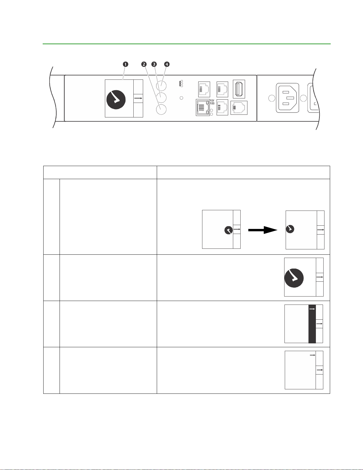
Rack PDU Front Panel
Serial
In
Out
y
USB
Reset
Main
Menu
Select
Scroll
- Warning
- OK
- Overload
pdu0713a
MA
apc
MA
apc12345678
MA
pdu0714a
MA
Pha
Ne
MA
Temp/ H u m i dit
SELECT
0
0
0
4.37 kW
MAIN
NOTE: Your Rack PDU is configured so the display backlight turns off after 10 minutes of inactivity. The
backlight can be turned on by depressing any button below the display.
Item Function
Network
x
pdu0711a
Display
Main Menu button
Scroll button
Select button
Shows information about the Rack PDU. In normal operation,
input voltage, current, and power refreshes every five seconds.
To reverse the text, select Display settings, scroll to Orientation
and press Select.
Device N
37.8%RH
24.5ºC
12345678
ame
SELECT
0
IN
0
24.5ºC
SELECT
37.8%RH
IN
Device Name
Press to view the Rack PDU electrical input.
SELECT
0
0
IN
1.23 kW
Press once to display the menu. Press
additional times to highlight the desired
menu option.
se Info
Outlet Current
SELECT
twork
IN
T em p/Humidity
With a menu option highlighted, press the
Select button to display Rack PDU
information. (Network information is shown
SELECT
at right.)
IPv4 Address
IN
10.234.576.89
pdu0712a
pdu0724a
pdu0715a
11Rack PDU User Guide
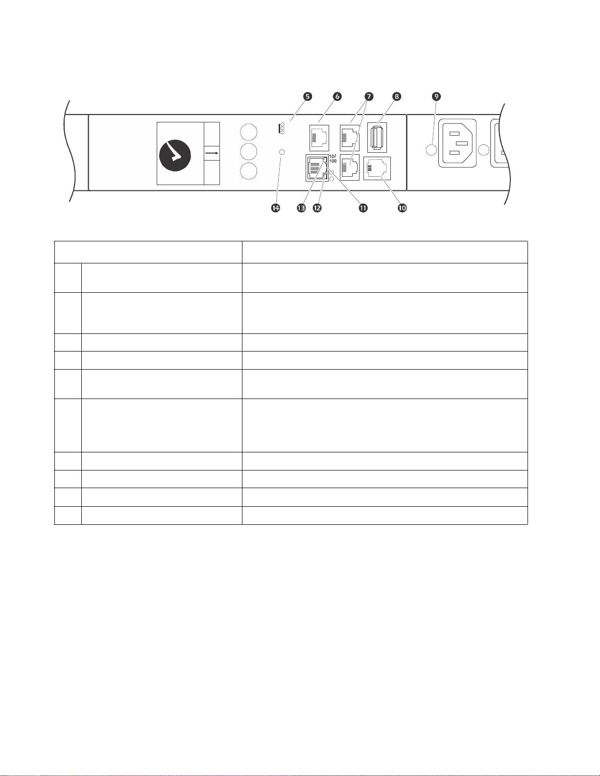
Page 20
Serial
In
Out
Temp/ H u m i dity
USB
Reset
Main
Menu
Select
Scroll
- Warning
- OK
- Overload
SELECT
0
0
0
4.37 kW
MAIN
Network
x
Item Function
Load Indicator LEDs Indicates the status of the Rack PDU load. See “Load indicator
LED” on page 13.
Temp/Humidity port Port for connecting an optional Schneider Electric Temperature
Sensor (AP9335T) or an optional Schneider Electric
Temperature/Humidity Sensor (AP9335TH).
pdu0740a
In and Out ports
USB port
Outlet status LED Illuminates green when the outlet is energized. ( Each outlet has
For use with the Network Port Sharing feature.
For use with a flash drive for firmware upgrades - 5V @ 100ma.
an outlet LED.)
RJ-12 Serial Port Port for connecting the Rack PDU to a terminal emulator
program for local access to the command line interface. Use the
supplied serial cable (Schneider Electric part number
940-0144A).
10/100 Base-T Connector
Network status LED
10/100 LED
Reset button
Connects the Rack PDU to the network.
See “Network Status LED” on page 13.
See “10/100 LED” on page 13.
Resets the Rack PDU without affecting the outlet status.
Rack PDU User Guide12
Page 21

Network Status LED
Condition Description
One of the following situations exists:
Off
Solid Green The Rack PDU has valid TCP/IP settings.
•The Rack PDU is not receiving input power.
•The Rack PDU is not operating properly. It may need to be repaired or
replaced. Contact Customer Support.
Solid Orange
Flashing Green The Rack PDU does not have valid
A hardware failure has been detected in the Rack PDU. Contact Customer
Support.
TCP/IP settings.
Flashing Orange The Rack PDU is making BOOTP requests.
Alternately flashing green
and orange
1. If you do not use a BOOTP or DHCP server, see “Establish Network Settings” on page 7 to configure the TCP/IP
settings of the Rack PDU.
2. To use a DHCP server, see “TCP/IP and Communication Settings” on page 113.
If the LED is flashing slowly , the Rack PDU is making DHCP
If the LED is flashing rapidly, the Rack PDU is starting up.
2
requests1.
10/100 LED
Condition Description
One or more of the following situations exists:
•The Rack PDU is not receiving input power.
•The cable that connects the Rack PDU to the network is disconnected or
Off
defective
•The device that connects the Rack PDU to the network is turned off.
•The Rack PDU itself is not operating properly. It may need to be repaired or
replaced. Contact Customer Support.
Solid green
The Rack PDU is connected to a network operating at 10 Me gabits per second
(Mbps).
Solid orange The Rack PDU is connected to a network operating at 100 Mbps.
Flashing green The Rack PDU is receiving or transmitting data packets at 10 Mbps.
Flashing orange The Rack PDU is receiving or transmitting data packets at 100 Mbps.
Load Indicator LED
The load indicator LED identifies near-overload (warning) and overload (critical) conditions for the Rack PDU.
Condition Description
Solid Green OK. No near-overload (warning) or overload (critical) alarms are present.
Solid Yellow
Flashing Red Overload. At least one overload (critical) alarm is present.
Warning. At least one near-overload (warning) alarm is present, but no
overload (critical) alarms are present.
13Rack PDU User Guide
Page 22
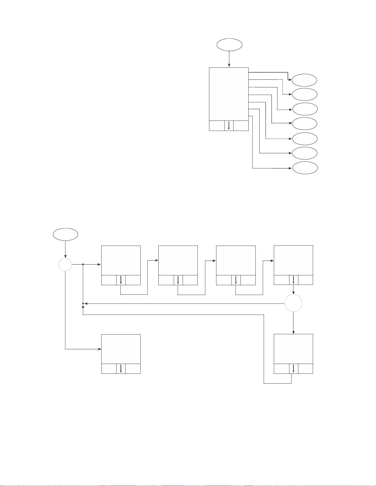
Example 1
Main
Menu
pdu071 8a
Temp/Humidity
Software Info
SKU/Serial #
SELECTMAIN
Phase Info
Display Settin gs
Network
SKU/SN
RF Code Control
RF Code
1. 14.1 A
2. 14.2 A
3. 14.3 A
SELECTMAIN
pdu0719a
Phase 2
208.0 V
14.2 A
1.23 kW
SELECTMAIN
Phase 3
208.0 V
14.3 A
1.23 kW
SELECTMAIN
SELECTMAIN
1
phase
Phase
Info
Phase
Outlets?
Y
e
s
No
Y
e
s
SELECTMAIN
Phase 1
208.0 V
14.1 A
1.23 kW
Input
208.0 V
14.1 A
SELECTMAIN
1.23 kW
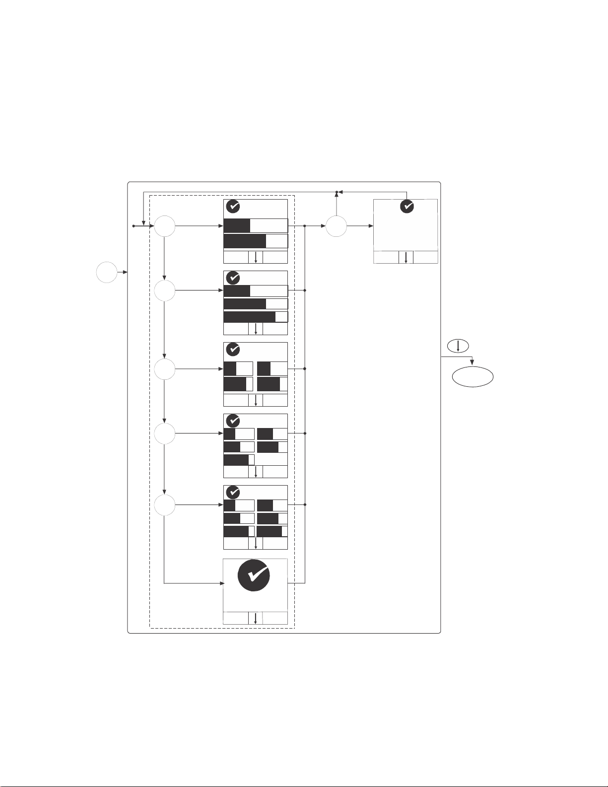
NOTE: The Menu Home Screen is restricted to four lines
per menu page. If there are more than four available
selections, they will appear on multiple pages. “Temp/
Humidity” only appears when an AP9335T or AP9335TH
sensor is attached.
Display Tree
Phase
Info
T/H
Network
SW Info
Disp
Settings
Phase Current
Phase to
No
Voltage
Rack PDU User Guide14
L1 - 2: 208V
L2 - 3: 208V
L3 -1: 208 V
Page 23
Example 2
pdu0710a
IPv4 Address
255.255.255.255
SELECTMAIN
Network
Sensor
Temp: 45.6ºC
Hum: 37.8%
SELECTMAIN SELECTMAIN
Model
AP8XXX
Serial Nu m ber
ZAxxxxxxxxxx
SELECTMAIN
APP
Enabled
SELECTMAIN
Press “Select”
WILL REBOOT
IPv6 Address
1234:5678:9012
3456:7890:1234
5678:9012
SELECTMAIN
00 00 00
00 00 00
SELECTMAIN
LCD Contrast
5 / 9
Press “Select”
SELECTMAIN
MAIN
LCD Backlight
Auto-On
to switch
MAIN
Normal
to switch
Hide
SELECTMAIN
to switchto adjust
No
Yes
each IPv6 addr)
SELECTMAIN
Disp. Settings
SKU/SN
SW Info
T/H
Display Tree
RF Code
Press “Select”
SELECT
AOS
5.0.0
5.0.0
IPv6 Address
(scrolls through
LCD Orientation
Press “Select”
SELECT
RF Code - Console
MAC Address
Network Port
Sharing Group
Display ID
Press “Select”
15Rack PDU User Guide
Page 24
Example 3
Main
Menu
pdu072 0a
2 bank
Yes
N
o
S
E
L
E
C
T
M
A
I
N
1
.
2
3
k
W
2
1
Sensor
N
o
S
E
L
E
C
T
M
A
I
N
1
.
2
3
k
W
2
1
3
3 bank
Yes
N
o
4 bank
Yes
N
o
5 bank
Yes
N
o
S
E
L
E
C
T
M
A
I
N
1
.
2
3
k
W
2
1
4
3
S
E
L
E
C
T
M
A
I
N
1
.
2
3
k
W
1
3
5
4
2
S
E
L
E
C
T
M
A
I
N
1
.
2
3
k
W
1
3
5
4
2
6
6 bank
Yes
S
E
L
E
C
T
M
A
I
N
0
0
1
.
2
3
k
W
MAIN
Monitor Status
Yes
0
5
º
C
.
2
4
8
%
H
R
.
7
3
c
e
a
m
v
i
N
e
D
c
1
a
p
M
A
N
I
e
8
7
6
4
5
2
3
T
C
E
L
E
S
Rack PDU User Guide16
Page 25
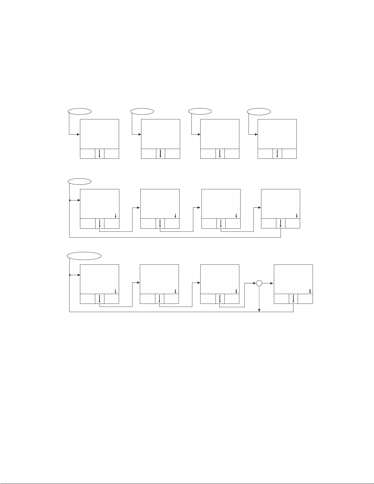
Example 4
S
E
L
E
C
T
M
A
I
N
0
2
4
.
5
º
C
3
7
.
8
%
R
H
D
e
v
i
c
e
N
a
m
e
a
p
c
1
2
3
4
5
6
7
8
S
E
L
E
C
T
M
A
I
N
1
.
2
3
k
W
1
3
5
4
2
6
S
E
L
E
C
T
M
A
I
N
0
0
1
.
2
3
k
W
S
E
L
E
C
T
M
A
I
N
5
.
6
7
k
W
1
3
5
4
2
6
S
E
L
E
C
T
M
A
I
N
5
9
.
0
º
C
3
0
.
0
%
R
H
D
e
v
i
c
e
N
a
m
e
a
p
c
1
2
3
4
5
6
7
8
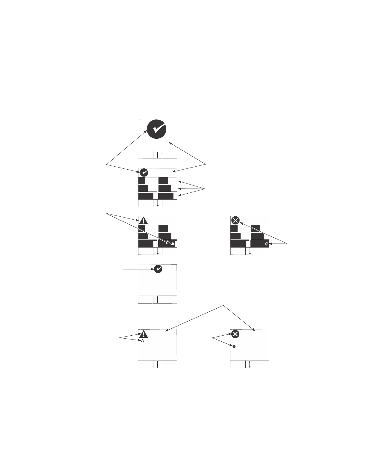
Normal Status
Indicator
Reading
Warning
(Near O verload)
Indicator
Critical
(Overload)
Indicator
Normal Status
Indicator
Threshold
Violation
Indicator
V
Monitor Status Indicators
Device Load
Bank Load Graphs
(No Indica tor = No rmal Status)
7
.
8
9
k
W
Warning
H
Most Critical
Sensor Status
p
e
h
T
g
m
i
Critical
Threshold
iolation
Indicator
1
2
3
4
5
6
M
N
A
I
S
E
L
E
C
T
m
i
u
d
y
i
H
t
L
w
o
.
C
2
5
4
º
H
0
.
1
0
R
%
N
a
e
m
e
D
c
v
i
e
6
7
8
4
5
3
2
c
1
a
p
N
I
A
M
C
L
T
E
E
S
pdu072 1a
17Rack PDU User Guide
Page 26
Command Line Interface
About the Command Line Interface (CLI)
You can use the command line interface to view the status of and configure and manage the Rack PDU (and
any connected Rack PDUs, if using the Network Port Sharing Feature). In addition, the command line interface
enables you to create scripts for automated operation. You can configure all parameters of a Rack PDU
(including those for which there are not specific CLI commands) by using the CLI to transfer an INI file to the
Rack PDU. The CLI uses XMODEM to perform the transfer, however, you cannot read the current INI file
through XMODEM.
Log on to the CLI
To access the command line interface, you can use either a local (serial) connection or a remote (Telnet or
SSH) connection with a computer on the same network as the Rack PDU.
Remote access to the command line interface
Y ou ca n choose to access the command line interface thro ugh Telnet and/or SSH. Telnet is enabled by default.
You do not have to enable either.
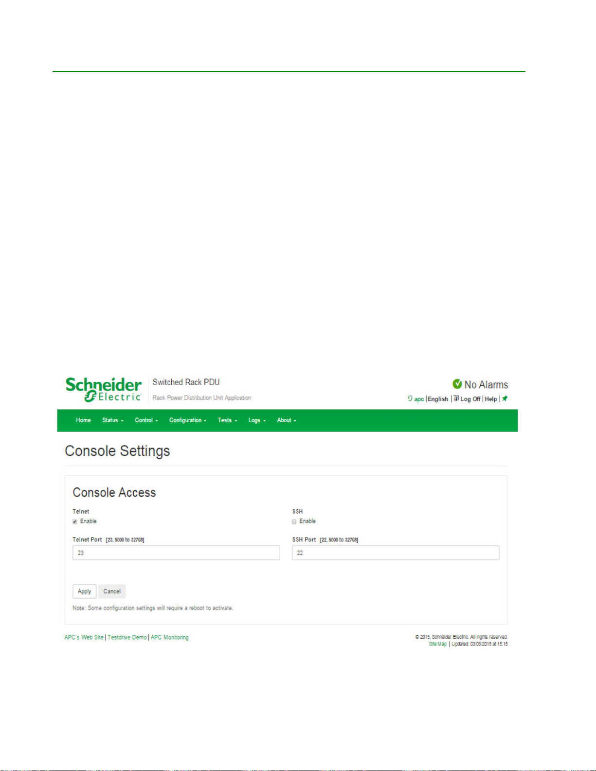
To enable or disable these access methods, use the web interface. On the Configuration tab, select Network
from the menu to open the Console Access page. Click to check the desired Enable box. Click Apply to save
your changes or Cancel to leave the page.
Rack PDU User Guide18
Page 27

Telnet for basic access
Telnet provides the basic security of authentication by user name and password, but not the high-security
benefits of encryption.
To use Telnet to access the command line interface:
1. From a computer that has access to the network on which the Rack PDU is installed, at a
command prompt, type telnet and the IP address for the Rack PDU (for example, telnet
139.225.6.133, when the Rack PDU uses the default Telnet port of 23), and press
If the Rack PDU uses a non-default port number (from 5000 to 327 68 ), you m ust in clu de a colon
or a space, depending on your Telnet client, between the IP address (or DNS name) and the port
number. (These are commands for general usage: Some clients do not allow you to specify the
port as an argument and some types of Linux might want extra commands).
2. Enter the user name and password (by default, apc and apc for the Super User).
If you cannot remember your user name or p assword, see “Recover ing from a Lost Password” on
page 10.
ENTER.
SSH for high-security access
If you use the high security of SSL for the Web interface, use SSH for access to the command line interface.
SSH encrypts user names, passwords, and transmitted data. The interface, user accounts, and user access
rights are the same whether you access the command line interface through SSH or Telnet, but to use SSH,
you must first configure SSH and have an SSH client program installed on your computer.
Local access to the command line interface
For local access, use a computer that connects to the Rack PDU through the serial port to access the
command line interface:
1. Select a serial port at the computer and disable any service that uses that port.
2. Connect the serial cable (Schneider Electric part number 940-0144A) from the selected serial
port on the computer to the Serial port on the Rack PDU.
3. Run a terminal program (e.g., HyperTerminal) and configure the selected port for 9600 bps, 8
data bits, no parity, 1 stop bit, and no flow control.
4. Press
ENTER. At the prompts, enter your user name and password.
19Rack PDU User Guide
Page 28

About the Main Screen
Schneider Electric Network Management Card AOS vx.x.x
(c) Copyright 2015 All Rights Reserved RPDU 2g vx.x.x
-------------------------------------------------------------------------Name : Test Lab Date : 6/30/2016
Contact : Don Adams Time : 5:58:30
Location : Building 3 User : Administrator
Up Time : 0 Days, 21 Hours, 21 Minutes Stat : P+ N4+ N6+ A+
Type ? For command listing
Use tcpip for IP address (-i), subnet (-s), and gateway (-g)
APC>
Following is an example of the main screen, which is displayed when you log on to the command line interface
of a Rack PDU.
• Two fields identify the operating system (AOS) and application (APP) firmware versions. The
application firmware name identifies the type of device that connects to the network. In the
example above, the application firmware for the Rack PDU is displayed.
Network Management Card AOS vx.x.x
RPDU 2g vx.x.x
• Three fields identify the system name, contact person, and location of the Rack PDU.
Name : Test Lab
Contact : Don Adams
Location : Building 3
• An Up Time field reports how long the Rack PDU Management Interface has been running since
it was last turned on or reset.
Up Time: 0 Days, 21 Hours, 21 Minutes
• Two fields identify when you logged in, by date and time.
Date: 06/30/2016
Time: 5:58:30
• The
• A
User field identifies whether you logged in through th e Super User , Administrator or Device
Manager account.
User: Administrator
Stat field reports the Rack PDU status.
Stat:P+ N4+ N6+ A+
P+ The APC operating system (AOS) is functioning properly.
IPv4
only
N+ N+ N4+ N6+ The network is functioning properly.
N? N6? N4? N6? A BOOTP request cycle is in progress.
N– N6- N4- N6- The Rack PDU failed to connect to the network.
N! N6! N4! N6! Another device is using the Rack PDU IP address.
* The N4 and N6 values can be different from one another: you could, for
example, have N4- N6+.
IPv6
only
IPv4 and
IPv6*
Description
Rack PDU User Guide20
Page 29

A+ The application is functioning properly.
A– The application has a bad checksum.
A? The application is initializing.
A! The application is not compatible with the AOS.
NOTE: If P+ is not displayed, contact the Schneider Electric Customer Care Center.
Using the CLI
At the command line interface, you can use commands to configure the Rack PDU. To use a command, type
the command and press
Options are case-sensitive.
While using the command line interface, you can also do the following:
• Type ? and press
• To obtain information about the purpose and syntax of a specified command, type the command,
a space, and ? or the word help. For example, to view RADIUS configuration options, type:
radius ?
or
radius help
• Press the
the
UP and DOWN arrow keys to scroll through a list of up to ten previou s com m and s .
• Type at least on e letter of a command and press the
commands that match the text you typed in the command line.
• Type exit or quit to close the connection to the command line interface.
ENTER. Commands and arguments are valid in lowercase, upperca se, or mixed case.
ENTER to view a list of available commands, based on your account type.
UP arrow key to view the command that was entered most recently in th e session. Use
TAB key to scroll through a list of valid
21Rack PDU User Guide
Page 30

Command Syntax
Item Description
- Options are preceded by a hyphen.
< >
[ ]
|
Example of a command that supports multiple options:
ftp [-p <port number>] [-S <enable | disable>]
In this example, the ftp command accepts the option -p, which defines the port number, and the option -S,
which enables or disables the FTP feature.
To change the FTP port number to 5010, and enable FTP:
Definitions of options are enclosed in angle brackets. For example:
-dp <device password>
If a command accepts multiple options or an option accepts mutually
exclusive arguments, the values may be enclosed in brackets.
A vertical line between items enclosed in brackets or angle bracket s indicates
that the items are mutually exclusive. You must use one of the items.
1. Type the ftp command, the port option, and the argument 5010:
ftp -p 5010
2. After the first command succeeds, type the ftp command, the enable/disable option, and the
enable selection:
ftp -S enable
Example of a command that accepts mutually exclusive arguments for an option:
alarmcount -p [all | warning | critical]
In this example, the option -p accepts only three argume nts: all, warning, or critical. For example, to view the
number of active critical alarms, type:
alarmcount -p critical
The command will fail if you type an argument that is not specified.
Rack PDU User Guide22
Page 31

Command Response Codes
The command response codes enable scripted operations to detect error conditions reliably without having to
match error message text:
The CLI reports all command operations with the following format:
E [0-9] [0-9] [0-9] : Error message
Code Message Code Message
E000 Success E200 Input Error
E001 Successfully Issued E201 No Response
E002 Reboot required for change to take effect E202 User already exists
E100 Command failed E203 User does not exist
E101 Command not found E204
E102 Parameter Error E205 Exceeds Maximum Users
E103 Command Line Error E206 Invalid value
E104 User Level Denial E207
E105 Command Prefill E208
E106 Data Not Available E209
E107
Serial communication with the
has been lost
Rack PDU
E210 Outlet Command Error: Outlet restricted.
User does not have access to this
command
Outlet Command Error: Device not
initialized.
Outlet Command Error: Previous command
is pending.
Outlet Command Error: Database rejected
request.
23Rack PDU User Guide
Page 32

Network Management Card Command Descriptions
? or help
Access: Super User, Administrator, Device User, Outlet User, Read Only
Description: View a list of all the CLI commands available to your account type. To view help text for a
specific command, type the command follo wed by a qu es tio n ma rk .
Parameters: [<command>]
Example 1:
apc> ?
Network Management Card Commands:
--------------------------------------------------------------------? about alarmcount boot cd date
delete dir eventlog exit format ftp
help ping portspeed prompt quit radius
reboot resetToDef system tcpip user web
xferINI xferStatus
Example 2:
apc> help boot
Usage: boot -- Configuration Options
boot [-b <dhcpBootp | dhcp | bootp | manual>] (Boot Mode)
[-a <remainDhcpBootp | gotoDhcpOrBootp>] (After IP
Assignment)
[-o <stop | prevSettings>] (On Retry Fail)
[-c <enable | disable>] (Require DHCP Cookie)
[-s <retry then stop #>] (Note: 0 = never)
[-f <retry then fail #>] (Note: 0 = never)
[-v <vendor class>]
[-i <client id>]
[-u <user class>]
Error Message: E000, E102
Rack PDU User Guide24
Page 33

about
Access: Super User, Administrator, Device User, Outlet User, Read Only
Description: Displays system information (Model Number, Serial Number, Manufacture Dates, etc.)
Parameters: None
Example: apc> about
E000: Success
Hardware Factory
--------------Model Number: APXXXX
Serial Number: ST0913012345
Hardware Revision: HW05
Manufacture Date: 3/4/2016
MAC Address: 00 05 A2 18 00 01
Management Uptime: 0 Days 1 Hour 42 Minutes
Error Message: E000
alarmcount
Access: Super User, Administrator, Device User, Outlet User, Read Only
Description: Displays alarms present in the system.
Parameters:
Option Argument Description
View the number of active alarms reported by the Rack PDU.
Information about the alarms is provided in the event log.
-p
Example:
all
warning View the number of active warning alarms.
critical View the number of active critical alarms.
To view all active warning alarms, type:
apc> alarmcount
E000: Success
AlarmCount: 0
Error Message: E000, E102
25Rack PDU User Guide
Page 34

boot
Access: Super User, Administrator
Description: Allows the user to get/set the network startup configuration of the device, such as setting boot
mode (DHCP vs BOOTP vs MANUAL).
Parameters:
Option Argument Description
-b
<boot
mode>
-c
-v [<vendor class>] Vendor Class is APC
-i [<client id>]
-u [<user class>] Th e name of the application firmware module.
Example:
Define how the TCP/IP settings will be configured when
dhcp | bootp | manual
[<enable | disable>]
(Require DHCP Cookie)
Using a DHCP server to obtain network settings:
apc> boot
E000: Success
Boot Mode: manual
Non-Manual Mode Shared Settings
------------------------------Vendor class: <device class>
Client id: XX XX XX XX XX XX
User class: <user class>
After IP assignment: gotoDhcpOrBootp
the Rack PDU turns on, resets, or restarts. See “TCP/IP
and Communication Settings” on page 113 for information
about each boot mode setting.
dhcp and dhcpBootp boot modes only . Ena ble or disable
the requirement that the DHCP server provide the APC
cookie.
The MAC address of the NMC, Which uniquely identifies it
on the network.
DHCP Settings
------------Retry then stop: 4
DHCP cookie is: enable
BOOTP Settings
-------------Retry then fail: never
On retry failure: prevSettings
Error Message:E000, E102
Rack PDU User Guide26
Page 35

cd
Access:Super User, Administrator, Device User, Outlet User, Read Only
Description:Allows the user to set the working directory of the file system. The working directory is set back
to the root directory ‘/’ when the user logs out of the CLI.
Parameters:<dicrectory name>
Example:
apc> cd logs
E000: Success
apc> cd /
E000: Success
Error Message:E000, E102
clrrst
Access: Super User, Administrator
Description: Clear reset reason.
Example: None
Error Message: None
27Rack PDU User Guide
Page 36

console
Access: Super User, Administrator
Description: Define whether users can access the command line interface using Telnet, which is enabled by
default, or Secure SHell (SSH), which provides protection by transmitting user names, passwords, and data in
encrypted form. You can change the Telnet or SSH port setting for additional security. Alternately, disable
network access to the command line interface.
Parameters:
Option Argument Description
Configure access to the command line interface, or use
-S disable | telnet | ssh
-t
-pt <telnet port n>
-ps <SSH port n>
-b
<enable | disable>]
(telnet)
2400 | 9600 | 19200 |
38400
the disable com mand to prevent access. Enabling SSH
enables SCP and disables Telnet.
Define the Telnet port used to communicate with the
Rack PDU (23 by default).
Define the SSH port used to communicate with the Rack
PDU (22 by default).
Configure the speed of the serial port connection (9600
bps by default).
Example 1:
To enable SSH access to the command line interface, type:
console -S ssh
Example 2: To change the Telnet port to 5000, type:
apc> console
E000: Success
Telnet: enabled
SSH: disabled
Telnet Port: 23
SSH Port: 22
Baud Rate: 9600
Error Message: E000, E102
Rack PDU User Guide28
Page 37

date
Access: Super User, Administrator
Definition: Get and set the date and time of the system.
To configure an NTP server to define the date and time for the Rack PDU, see “Date/Time screen” on
page 129.
Parameters:
Option Argument Description
-d <“datestring”> Set the current date. The format must match the current -f setting.
-t <00:00:00>
mm/dd/yy |
dd.mm.yyyy |
-f
-z
mmm-dd-yy |
dd-mmm-yy |
yyyy-mm-dd
<time zone
offset>
Configure the current time, in hours, minutes, and seconds. Use the
24-hour clock format.
Select the numerical format in which to display all dates in this user
interface. Each letter m (for month), d (for day), and y (for year)
represents one digit. Single-digit days and months are displayed with a
leading zero.
Set the difference with GMT in order to specify your time zone. This
enables you to synchronize with other people in different time zones.
Example 1:
To display the date using the format yyyy-mm-dd, type:
date -f yyyy-mm-dd
Example 2: To define the date as October 30, 2015, using the format configured in the preceding example,
type:
date -d “2015-10-30”
Example 3: To define the ti m e as 5: 21 :0 3 p. m., type:
date -t 17:21:03
Error Message: E000, E100, E102
delete
Access: Super User, Administrator
Description: Delete a file in the file system.
Parameters:
Argument Description
<file name> Type the name of the file to delete.
Example:
apc> delete /db/prefs.dat
E000: Success
Error Messages: E000, E102
29Rack PDU User Guide
Page 38

dir
Access: Super User, Administrator, Device User, Outlet User, Read Only
Description: Displays the content of the working directory.
Parameters: None
Example: apc> dir
E000: Success
--wx-wx-wx 1 apc apc 3145728 Mar 3 2015 aos.bin
--wx-wx-wx 1 apc apc 3145728 Mar 4 2015 app.bin
-rw-rw-rw- 1 apc apc 45000 Mar 6 2015 config.ini
drwxrwxrwx 1 apc apc 0 Mar 3 2015 db/
drwxrwxrwx 1 apc apc 0 Mar 3 2015 ssl/
drwxrwxrwx 1 apc apc 0 Mar 3 2015 ssh/
drwxrwxrwx 1 apc apc 0 Mar 3 2015 logs/
drwxrwxrwx 1 apc apc 0 Mar 3 2015 sec/
drwxrwxrwx 1 apc apc 0 Mar 3 2015 dbg/
drwxrwxrwx 1 apc apc 0 Mar 3 2015 pdu/
Error Messages: E000
Rack PDU User Guide30
Page 39

dns
Access: Super User, Administrator
Definition: Configure the manual Domain Name System (DNS) settings.
Parameters:
Parameter Argument Description
-OM
-p
-s
-d <domain name> Set the domain name.
-n
-h <host name> Set the host name.
-y
Example:
apc> dns
E000: Success
Active Primary DNS Server: x.x.x.x
Active Secondary DNS Server: x.x.x.x
enable |
disable
<primary DNS
server>
<secondary
DNS server>
<domain name
IPv6>
<enable |
disable>
Override the manual DNS.
Set the primary DNS server.
Set the secondary DNS server.
Set the domain name IPv6.
System-hostname sync
Override Manual DNS Settings: enabled
Primary DNS Server: x.x.x.x
Secondary DNS Server: x.x.x.x
Domain Name: example.com
Domain Name IPv6: example.com
System Name Sync: Enabled
Host Name: ExampleHostName
Error Message: E000, E102
31Rack PDU User Guide
Page 40

Access: Super User, Administrator
Description: View email
Parameters:
Parameters Argument
-g[n] <enable | disable> (Generation)
-t[n] <To Address>
-o[n] <long | short> (Format)
-l[n] <Language Code>
-r [n] <Local | recipient | custom> (Route)
Custom Route Option
-f[n] <From Address>
-s{n} <SMTP Server>
-p[n] <Port>
-a[n] <enable | disable> (Authentication)
-u[n] <User Name>
-w[n] <Password>
-e[n]
-c[n]
-i[n] <Certificate File Name>
n= Email Recipient Number 1,2,3 or 4)
<none | ifsupported | always |
implicit> (Encryption)
<enable | disable > (Required
Certificate)
Example:
apc>email
E000: Success
Recipient: 1
Generation: enabled
Address: example@example.com
Format: long
Language: enUs - English
Route: local
Error Message: E000, E102
Rack PDU User Guide32
Page 41

eventlog
Access: Super User, Administrator, Device User, Outlet User, Read Only
Description: View the date and time you retrieved the event log, the status of the Rack PDU, and the status
of sensors connected to the Rack PDU. View the most recent device events and the date and time they
occurred. Use the following keys to navigate the event log:
Parameters:
Key Description
ESC
ENTER
SPACEBAR
B
D
Example:
Close the event log and return to the command line interface.
Update the log display . Use this command to view events that were record ed after you
last retrieved and displayed the log.
View the next page of the event log.
View the preceding page of the event log. This command is not available at the main
page of the event log.
Delete the event log. Follow the prompts to confirm or deny the deletion. Deleted
events cannot be retrieved.
apc> eventlog
---- Event Log ---------------------------------------------------- Date: 03/06/2016 Time: 13:22:26
----------------------------------- Metered Rack PDU: Communication Established
Date Time Event
-------------------------------------------------------------- 03/06/2016 13:17:22 System: Set Time.
03/06/2016 13:16:57 System: Configuration change. Date format
preference.
03/06/2016 13:16:49 System: Set Date.
03/06/2016 13:16:35 System: Configuration change. Date format
preference.
03/06/2016 13:16:08 System: Set Date.
03/05/2016 13:15:30 System: Set Time.
03/05/2016 13:15:00 System: Set Time.
03/05/2016 13:13:58 System: Set Date.
03/05/2016 13:12:22 System: Set Date.
03/05/2016 13:12:08 System: Set Date.
03/05/2016 13:11:41 System: Set Date.
<ESC>- Exit, <ENTER>- Refresh, <SPACE>- Next, <D>- Delete
Error Message: E000, E100
33Rack PDU User Guide
Page 42

exit, quit, or bye
Access: Super User, Administrator, Device User, Outlet User, Read Only
Description: Exit from the CLI session. The exit, quit, and bye commands all clos e th e CLI sessio n .
Parameters: None
Example:
apc> exit
Bye
Error Message: None
firewall
Access: Super User, Administrator
Description: Establishes a barrier between a trusted, secure internal network and another network.
Parameters:
Parameters Argument Description
-S <enable | disable> Enable or disable the Firewall.
-f <file name to activate>
-t
-fe No argument. List only Shows active file errors.
-te No argument. List only Shows test file errors.
-c No argument. List only Cancel a firewall test.
-r No argument. List only Shows active firewall rules.
-l No argument. List only Shows firewall activity log.
<file name to test>
<duration time in minutes>
Name of the firewall to
activate.
Name of firewall to test and
duration time in minutes.
Error Message:
E000, E102
format
Access: Super User, Administrator
Description: Allows the user to format the FLASH file system. This will delete all configuration data, event
and data logs, certificates and keys. NOTE: The user must confirm by entering “YES” when prompted.
Parameters: None
Example:
apc> format
Format FLASH file system
Warning: This will delete all configuration data,
event and data logs, certs and keys.
Enter 'YES' to continue or <ENTER> to cancel:
apc>
Error Message: None
Rack PDU User Guide34
Page 43

ftp
Access: Super User, Administrator
Description: Get/set the ftp configuration data,
NOTE: The system will reboot if any configuration is changed.
Parameters:
Option Argument Definition
Define the TCP/IP port that the FTP server uses to
communicate with the Rack PDU (21 by default). The FTP
server uses both the specified port and the port one number
lower than the specified port.
-p
-S enable | disable Configure access to the FTP server.
Example:
<port number>
(valid ranges are:
21 and 5000-32768)
To change the TCP/IP port to 5001, type:
apc> ftp -p 5001
E000: Success
apc> ftp
E000: Success
Service: Enabled
Ftp Port: 5001
apc> ftp -p 21
E000: Success
Error Message:E000, E102
lang
Access: Super User, Administrator, Device User, Outlet User
Description: Displays the language in use
Parameters: None
Example:
apc>lang
E000: Success
Languages
enUs - English
Error Message: None
35Rack PDU User Guide
Page 44

lastrst
Access: Super User, Administrator
Description: Last reset reason
Parameters: None
Example:
apc> lastrst
00 Reset Cleared
E000: Success
Error Message: E000, E102
ledblink
Access: Super User, Administrator
Description: Sets the blink rate to the LED on the Rack Power Distribution Unit.
Parameters: <time> = Number of minutes to blink the LED
Example:
apc> ledbllink 1
E000: Success
Error Message: E000, E102
logzip
Access: Super User, Administrator
Description: Places large logs into a zip file before sending.
Parameters:
[-m <email recipient>] (email recipient number (1-4))
Example:
apc> logzip
Generating files
Compressing files into /dbg/debug_ZA1023006009.tar
E000: Success
Error Message: E000, E102
Rack PDU User Guide36
Page 45

netstat
Access: Super User, Administrator
Description: Displays incoming and outgoing network connections.
Parameters: None
Example:
apc> netstat
Current IP Information:
Family mHome Type IPAddress Status
IPv6 4 auto FE80::2C0:B7FF:FE51:F304/64 configured
IPv6 0 manual ::1/128 configured
IPv4 0 manual 127.0.0.1/32 configured
Error Message: E000, E102
ntp
Access: Super User, Administrator
Description: Synchronizes the time of a computer client or server.
Parameters:
Option Argument Definition
-OM enable | disable Override the manual settings.
-p <primary NTP server> Specify the primary server.
-s <secondary NTP server> Specify the secondary server.
Example 1:
To enable the ov er rid e of manu al set t ing, type:
ntp -OM enable
Example 2: To specify the primary NTP server, type:
ntp -p 150.250.6.10
Error Message: E000, E102
37Rack PDU User Guide
Page 46

ping
Access: Super User, Administrator, Device User
Description: Perform a network ‘ping’ to any external network device.
Parameters:
Argument Description
<IP address or DNS name>
Type an IP address with the format xxx.xxx.xxx.xxx, or the DNS
name configured by the DNS server.
Example:
apc> ping 192.168.1.50
E000: Success
Reply from 192.168.1.50: time(ms)= <10
Reply from 192.168.1.50: time(ms)= <10
Reply from 192.168.1.50: time(ms)= <10
Reply from 192.168.1.50: time(ms)= <10
Error Message:E000, E100, E102
portSpeed
Access: Super User, Administrator
Description: Allows the user to get/set the network port speed.
NOTE: The system will reboot if any configuration is changed.
Parameters:
Option Arguments Description
auto | 10H |
-s
H = Half Duplex
F = Full Duplex
10F | 100H |
100 F
Define the communication speed of the Ethernet port. The auto
command enables the Ethernet devices to negotiate to transmit at
the highest possible speed. See “Port Speed” on page 115 for more
information about the port speed settings.
10 = 10 Meg Bits
100 = 100 Meg Bits
Example:
apc> portspeed
E000: Success
Port Speed: 10 Half_Duplex
apc> portspeed -s 10h
E000: Success
apc> portspeed
E000: Success
Port Speed: 10 Half_Duplex
apc> portspeed -s auto
E000: Success
Error Message: E000, E102
Rack PDU User Guide38
Page 47

prompt
Access: Super User, Administrator, Device User
Description: Allows the user to change the format of the prompt, either short or long.
Parameters:
Option Argument Description
-s
long The prompt includes the account type of the currently logged-in user.
short The default setting. The prompt is four characters long: APC>
Example:
apc> prompt –s long
E000: Success
Administrator@apc>prompt –s short
E000: Success
Error Message: E000, E102
pwd
Access: Super User, Administrator, Device User, Read Only
Description: Used to output the path of the current working directory.
Parameters: None
Example:
apc> pwd
/
apc> cd logs
E000: Success
apc> pwd
/logs
Error Message: E000, E102
39Rack PDU User Guide
Page 48

radius
Access:Super User, Administrator
Description:View the existing RADIUS settings, enable or disable RADIUS authentication, and configure
basic authentication parameters for up to two RADIUS servers.
For a summary of RADIUS server configuration and a list of supported RADIUS servers, see “Configure the
RADIUS Server” on page 111.
Additional authentication parameters for RADIUS servers are available at the Web interface of the Rack PDU.
See “RADIUS” on page 110 for more information.
For detailed information about configuring your RADIUS serve r, see the Security Handbook, available at
www.apc.com.
Parameters:
Option Argument Description
Configure RADIUS authentication:
local—RADIUS is disabled. Local authentication is enabled.
-a
-p1
-p2
-s1
-s2
-t1
-t2
local |
radiusLocal
| radius
<server IP>
<server
secret>
<server
timeout>
radiusLocal—RADIUS, then Local Authentication. RADIUS and
local authentication are enabled. Authentication is requested from the
RADIUS server first. If the RADIUS server fails to respond, local
authentication is used.
radius—RADIUS is enabled. Local authentication is disabled.
The server name or IP address of the primary or sec ond ar y R ADIUS
server.
NOTE: RADIUS servers use port 1812 by default to authentic ate
users. To use a different port, add a colon followed by the new port
number to the end of the RADIUS server name or IP address. The
Rack PDU supports ports 1812, 5000 to 32768.
The shared secret between the primary or secondary RADIUS server
and the Rack PDU .
The time in seconds that the Rack PDU waits for a response from the
primary or secondary RADIUS server.
Example 1:
To view the existing RADIUS settings for the Rack PDU, type radius and press ENTER.
Example 2: To enable RADIUS an d loc al au th en tic atio n, ty pe:
apc> radius -a radiusLocal
E000: Success
Example 3: To configure a 10-second timeout for a secondary RADIUS server, type:
apc> radius -t2 10
E000: Success
Error Message: E000, E102
Rack PDU User Guide40
Page 49

reboot
Access: Super User, Administrator
Description: Restart the NMC interface of the Rack PDU only. Forces the network device to reboot. User
must confirm this operation by entering a “YES” after the command has been entered.
Parameters: None
Example:
apc> reboot
E000: Success
Reboot Management Interface
Enter 'YES' to continue or <ENTER> to cancel : <user enters ‘YES’>
Rebooting...
Error Message: E000, E100
resetToDef
Access: Super User, Administrator
Description: Reset all parameters to their default.
Parameters:
Option Arguments Description
-p all | keepip
Example:
To reset all of the configuration changes except the TCP/IP settings for the Rack PDU, type:
resetToDef -p keepip
Enter 'YES' to continue or <ENTER> to cancel : : <user enters ‘YES’>
all User Names, Passwords.
Please wait...
Please reboot system for changes to take effect!
Error Message: E000, E100
all = all configuration data, including the IP address.
keepip = all configuration data, except the IP address.
Reset all configuration changes, including event actions, device
settings, and, optionally, TCP/IP configuration settings.
41Rack PDU User Guide
Page 50

session
Access: Super User, Administrator
Description: Records who is logged in, the serial, time and ID.
Parameters:
Option Arguments
-d [-d <session nID>] (Delete)
-M <Enable | disable> (Multi-User Enable)
-a <enable | disable (Remote Authentication Override)
Example:
apc>session
User Interface Address Logged In Time ID
-------------------------------------------------------------------apc Web x.x.x.x 00:00:08 156
apc Telnet x.x.x.x 00:00:02 157
E000: Success
Error Message: E000, E102
smtp
Access: Super User, Administrator
Description: Internet standard for electronic mail.
Parameters:
Option Argument
-f <From Address
-s <SMTP Server>
-p <Port>
-a <enable | disable> (Authentication)
-u <User Name>
-w <Password>
-e <none | ifavail | always | implicit> (Encryption)
-c <enable | disable> (Require Certificate)
-i <Certificate File Name>
1
Port options are 25, 465, 587, 5000 to 32768
1
Example:
apc> smtp
E000: Success
From: address@example.com
Server: mail.example.com
Port: 25
Auth: disabled
User: User
Password: <not set>
Encryption: none
Req. Cert: disabled
Cert File: <n/a>
Error Message: E000, E102
Rack PDU User Guide42
Page 51

snmp
Access: Super User, Administrator
Description: Enable or disable SNMP 1 or SNMP 3.
Parameters:
Option Arguments Description
-c <Community> Identify the group of Rack PDUs
-a <read | write | writeplus | disable> Set the access level
-n <IP or Domain Name> The host’s name or address
-S <enable | disable>
Enable or disable the respective version
of SNMP, 1 or 3
Example:
To enable SNMP ver sio n 1, type :
apc> snmp
E000: Success
SNMPv1: enabled
Access Control summary:
Access Control #: 1
Community: public
Access Type: read
Address: 0.0.0.0
Access Control #: 2
Community: private
Access Type: write +
Address: 0.0.0.0
Access Control #: 3
Community: public2
Access Type: disabled
Address: 0.0.0.0
Access Control #: 4
Community: private2
Access Type: disabled
Address: 0.0.0.0
Error Message: E000, E102
43Rack PDU User Guide
Page 52

snmpv3
Access: Super User, Administrator
Description: Enable or disable SNMP 3.
Parameters:
Option Arguments Description
-S enable | disable
-u [n] User Name User Name
-c [n] <Community> Identify the group of Rack PDUs
-a [n] <read | write | writeplus | disable> Set the access level
-n [n] <IP or Domain Name> The host’s name or address
-ap [n] <sha | md5 | none> (Authentication Protocol)]
-pp [n] <aes | des | none> (Privacy Protocol)]
-ac [n] <enable | disable> (Access)
-au [n] <Nms Ip>] [n] = Access Control # = 1,2,3, or 4)
Example:
apc> snmpv3
E000: Success
SNMPv3 Configuration
SNMPV3: disabled
Enable or disable the respective version
of SNMP
SNMPv3 User Profiles
Index: 1
User Name: apc snmp profile1
Authentication: None
Encryption: None
Index: 2
User Name: apc snmp profile2
Authentication: None
Encryption: None
Index: 3
User Name: apc snmp profile3
Authentication: None
Encryption: None
Index: 4
User Name: apc snmp profile4
Authentication: None
Encryption: None
Rack PDU User Guide44
Page 53

SNMPv3 Access Control
Index: 1
User Name: apc snmp profile1
Access: disabled
NMS IP/Host Name: 0.0.0.0
Index: 2
User Name: apc snmp profile2
Access: disabled
NMS IP/Host Name: 0.0.0.0
Index: 3
User Name: apc snmp profile3
Access: disabled
NMS IP/Host Name: 0.0.0.0
Index: 4
User Name: apc snmp profile4
Access: disabled
NMS IP/Host Name: 0.0.0.0
Error Message: E000, E102
45Rack PDU User Guide
Page 54

snmptrap
Access: Super User, Administrator
Description: Enable or disable SNMP trap generation
Parameters:
Option Arguments
-c{n} <Community>
-r[n] <Receiver NMS IP>
-l[n] <Language> [language code]
-t[n] <Trap Type> [snmpV1 | snmpV3]]
-g[n] <Generation> [enable | disable]
-a[n] <Auth Trap> [enable | disable]
-u[n] <profile1 | profile2 | profile3 | profile4> (User Name)
n=Trap reciever # = 1,2,3,4,5 or 6
Example:
apc> snmptrap
E000: Success
SNMP Trap Configuration
Index: 1
Receiver IP: x.x.x.x
Community: public
Trap Type: SNMPV1
Generation: disabled
Auth Traps: enabled
User Name: apc snmp profile1
Language: enUs - English
Error Message: E000, E102
Rack PDU User Guide46
Page 55

system
Access: Super User, Administrator
Description: View and set the system name, the contac t, the location and view up time as well as the date
and time, the logged-on user, and the high-level system status P, N, A (see “About the Main Screen” on
page 20 for more information about system status).
Parameters:
Option Argument Description
-n <system-name> Define the device name, the name of the person responsible for
-c <system-contact>
-l <system-location>
-m <system-message>
<enable | disable>]
-s
(system-hostname
sync)
the device, and the physical location of the device.
NOTE: If you define a value with more than one word, you must
enclose the value in quotation marks.
These values are also used by St ruxureWare and the Rack
PDU’s SNMP agent.
When defined, a custom message will appear on the log on
screen for all users.
Allow the host name to be synchronized with the system name
so both fields automatically contain the same value.
NOTE: When enabling this feature, the system name identifier
can no longer contain a space character (since it will be
synchronized to the host name field).
Example 1:
To set the device location as Test Lab, type:
apc> system -l “Test Lab”
E000: Success
Example 2: To view the device name, type:
apc> system -n
E000: Success
Name: : Rack 2 in Room #222
Error Message: E000, E102
47Rack PDU User Guide
Page 56

tcpip
Access: Super User, Administrator
Description: View and manually configure these network settings for the Rack PDU:
Parameters:
Option Argument Description
-i <IP address>
-s <subnet mask> Type the subnet mask for the Rack PDU.
-g <gateway>
-d <domain name> Type the DNS name configured by the DNS server.
-h <host name> Type the host name that the Rack PDU will use.
-S enable | disable Enable or disable IPv4.
Example 1:
To view the network settings of the Rack PDU, type tcpip and press ENTER.
apc> tcpip
E000: Success
IP Address: 192.168.1.50
MAC Address: XX XX XX XX XX XX
Subnet Mask: 255.255.255.0
Gateway: 192.168.1.1
Domain Name: example.com
Host Name: HostName
Type the IP address of the Rack PDU, using the format
xxx.xxx.xxx.xxx
Type the IP addres s of the default gateway. Do not use the
loopback address (127.0.0.1) as the default gateway.
Example 2: To view the IP address of the Rack PDU, type:
apc> tcpip -i
E000: Success
IP Address: 192.168.1.50
Example 3: To manually configure an IP address of 192.168.1.49 for the Rack PDU, type:
apc> tcpip -i 192.168.1.49
E000: Success
Reboot required for change to take effect
Error Message: E000, E102
Rack PDU User Guide48
Page 57

tcpip6
Access: Super User, Administrator
Description: Enable IPv6 and view and manually configure these network settings for the Rack PDU:
Parameters:
Option Argument Description
-S enable | disable Enable or disable IPv6.
-man enable | disable
-auto enable | disable
-i <IPv6 address> Set the IPv6 address of the Rack PDU.
-g <IPv6 gateway> Set the IPv6 address of the default gateway.
-d6
router | statefull
| statelss | never
Enable manual addressing for the IPv6 address of the Rack
PDU.
Enable the Rack PDU to automatically configure the IPv6
address.
Set the DHCPv6 mode, with parameters of router controlled,
statefull (for address and other information, they maintain their
status), stateless (for information other than address, the
status is not maintained), never.
Example:
To view the network settings of the Rack PDU, type tcpip6 and press ENTER.
apc> tcpip6
E000: Success
IPv6: enabled
Manual Settings: disabled
IPv6 Address: ::/64
MAC Address: XX XX XX XX XX XX
Gateway: ::
IPv6 Manual Address: disabled
IPv6 Autoconfiguration: enabled
DHCPv6 Mode: router controlled
Error Message: E000, E102
49Rack PDU User Guide
Page 58

user
Access: Super User, Administrator
Description: Configure the user name, password, and inactivity timeout fo r each account type. You can’t edit
a user name, you must delete it and then create a new user. For information on the permissions granted to
each account type, see “Types of User Accounts” on page 2.
Parameters:
Option Argument Description
-n <user>
-pw <user password>
-pe <user permission>
-d
-e enable | disable
-st <session timeout>
-sr enable | disable
-el enable | disable Indicate the Event Log color coding.
-lf tab | csv Indicate the format for exporting a log file.
-ts us | metric Indicate the temperature scale, Fahrenheit or Celsius.
<user description>
Specify these options for a user.
Enable overall access.
Specify how long a session lasts waits before logging off a
user when the keyboard is idle.
Bypass RADIUS by using the serial console (CLI)
connection, also known as Serial Remote Authentication
Override
-df <mm/dd/yyyy |
-lg
-del <user name> Delete a user.
-l Display the current user list.
Example:
dd.mm.yyyy | mmm-ddyy | dd-mmm-yy |
yyyy-mm-dd>
<language code (e.g.
enUs)>
apc> user -n apc
E000: Success
Access: Enabled
User Name: apc
Password: <hidden>
User Permission: Super User
User Description: User Description
Session Timeout: 3 minutes
Serial Remote Authentication Override: Disabled
Event Log Color Coding: Enabled
Export Log Format: Tab
Temperature Scale: Metric
Date Format: mm/dd/yyyy
Language: English (enUs)
Outlets: All
Specify a date format.
Specify a user language.
Error Message: E000, E102
Rack PDU User Guide50
Page 59

userdflt
Access: Super User, Administrator
Description: Complimentary function to “user” establishing default user preferences. There are two main
features for the default user settings:
Determine the default values to populate in each of the fields when the Super User or Administrator-level
account creates a new user. These values can be changed before the settings are applied to the system.
For remote users (user accounts not stored in the system that are remotely authenticated such as RADIUS)
these are the values used for those that are not provided by the authenticating server. For example, if a
RADIUS server does not provide the user with a temperature preference, the value defined in this section will
be used.
Parameters:
Options
-e <enable | disable> (Enable)
-pe
-d <user description>
-st <session timeout> minute(s)
-bl <bad login attempts>
-el
-lf
-ts
-df
-lg <language code (enUs, etc)>
-sp <enable | disable>
-pp <interval in days>
Argument Description
By default, user will be enabled or disabled upon creation.
Remove (Enable) from the end
<Administrator | Device |
Read-Only | Network-Only>
(user permission)
<enable | disable>
(Event Log Color Coding)
<tab | csv>
(Export Log Format)
<us | metrics>
(Temperature Scale)
<mm/dd/yyyy | dd.mm.yyyy |
mmm-dd-yy | dd-mmm-yy |
yyyy-mm-dd> (Date Format)
Specify the user's permission level and account type.
Provide a user description.
Provide a default session timeo u t .
Number of incorrect login attempts a user has before the
system disables their account. Upon reaching this limit, a
message is displayed informing the user the account has
been locked. The Super User or an Administrator-level
account is needed to re-enable the account to allow the
user to log back in.
NOTE:
can be manually disabled if necessary.
Enable or disable event log color coding.
Specify the log export format, tab or CSV.
Specify the user's temperature scale. This setting is also
used by the system when a user preference is not
available (for example, email notifications).
Specify the user's preferred date format.
User language
Strong password
Required password change interval
A Super User account cannot be locked out, but
Example:
apc> userdflt
E000: Success
Access: Disabled
User Permission: Administrator
User Description: User Description
Session Timeout: 3 minutes
Bad Login Attempts: 0
Event Log Color Coding: Enabled
Export Log Format: Tab
Temperature Scale: Metric
Date Format: mm/dd/yyyy
Language: English (enUs)
Strong Passwords: Disabled
Require Password Change: 0 day(s) (Disabled)
Error Message: E000, E102
51Rack PDU User Guide
Page 60

web
Access: Super User, Administrator
Description: Enable access to the Web interface using HTTP or HTTPS.
For additional security, you can change the port setting for HTTP and HTTPS to any unused port from 5000 to
32768. Users must then use a colon (:) in the address field of the browser to specify the port number. For
example, for a port number of 5000 and an IP address of 152.214.12.114, type:
http://152.214.12.114:5000
Parameters:
Option Argument Definition
-h enable | disable Enable or disable access to the user interface for HTTP.
Enable or disable access to the user interface for HTTPS.
-s enable | disable
-ph <http port #>
-ps <https port #>
-mp <minimum protocol> Choices are: SSL3.0 | TLS1.0 | TLS1.1 | TLS1.2
When HTTPS is enabled, data is encrypted during
transmission and authenticated by digital certificate.
Specify the TCP/IP port used by HTTP to communicate
with the Rack PDU (80 by default). The other available
range is 5000–32768.
Specify the TCP/IP port used by HTTPS to communicate
with the Rack PDU (443 by default). The other available
range is 5000–32768.
Example 1:
To prevent all access to the web interface, type:
apc> web -h disable -s disable
Example 2: To define the TCP/IP port used by HTTP, type:
apc> web
E000: Success
HttP: enabled
Https: disabled
Http Port: 80
Https Port: 443
Minimum Protocol: TLS1.1
apc> web -ph 80
E000: Success
Error Message: E000, E102
whoami
Access: Super User, Administrator, Device Only, Read Only
Description: Provides login information on the current user.
Parameters: None
Example:
apc> whoami
E000: Success
admin
Error Message: E000, E102
Rack PDU User Guide52
Page 61

xferINI
Access: Super User, Administrator
Description: Use XMODEM to upload an INI file while you are accessing the command line interface through
a serial connection. After the upload completes:
• If there are any system or network changes, the command line interface restart s and you must log
on again.
• If you selected a baud rate for the file transfer that is not the same as the default baud rate for the
Rack PDU, you must reset the baud rate to the default to reestablish comm u nic at ion with th e
Rack PDU.
Parameters: None
Example:
apc> xferINI
Enter 'YES' to continue or <ENTER> to cancel : <user enters ‘YES’>
------- File Transfer Baud Rate----------------------------- 1- 2400
2- 9600
3- 19200
4- 38400
> <user enters baudrate selection>
Transferring at current baud rate (9600), press <ENTER>...
<user presses <ENTER>>
Start XMODEM-CRC Transfer Now!
CC
<user starts sending INI>
150 bytes have successfully been transmitted.
apc>
Error Message: None
xferStatus
Access: Super User, Administrator
Description: View the result of the last file transfer. See “Verifying Upgrades and Updates” on page152 for
descriptions of the transfer result codes.
Parameters: None
Example:
apc> xferStatus
E000: Success
Result of last file transfer: Failure unknown
Error Message: E000
53Rack PDU User Guide
Page 62

Device Command Descriptions
Network Port Sharing Commands
The CLI allows commands to be sent to guest Rack PDUs. The user may specify the Display ID of the Rack
PDU to be commanded, followed by a colon, before the first argument (or as the first argument, if the
command does not normally have arguments). Providing a Display ID is optional, omitting it will simply
command the local Rack PDU. For example: <command> [id:] <arg1> <arg2>
This will send <command> to the Rack PDU with the Display ID [id:].
[id:] is delimited from <arg1> with a colon character; do not include any spaces between [id:] <arg1>,
as spaces are used to delimit arguments.
alarmList
Access: Super User, Administrator, Device User
Description: Displays alarms present on the device (or anothe r device in the group if Network Po rt Sharing is
used.)
Parameters: None.
Example: To view all active warning alarms, type:
apc> alarmList
-----Device Alarm Status------------------ 1 Critical Alarm Present.
------------------------------------------[Critical] rack PDU 1: Internal power supply #2 fault, under voltage.
<ESC>- Exit, <ENTER>- Refresh
Error Message: E102
bkLowLoad
Access: Super User, Administrator, Device User
Description: Set or view the bank low-load threshold current in amps. You can specify all banks, a single
bank, a range, or a comma-separated list of single banks and/or ranges.
Parameters:
[id#:] <all | bank#> [current]
bank# = A single number or a range of numbers separated with a dash or a comma;
separated list of single bank number and/or number ranges.
current = The new bank threshold (Amps)
Example 1: To set the low-load threshold for all banks to 1A, type:
apc> bkLowLoad all 1
E000: Success
Example 2: To view the low-load threshold setting for banks 1 through 3, type:
apc> bkLowLoad 1-3
E000: Success
1: 1 A
2: 1 A
3: 1 A
Error Messages: E000, E102
Rack PDU User Guide54
Page 63

bkNearOver
Access: Super User, Administrator, Device User
Description: Set or view the bank near-overload threshold current in amps. You can specify all banks, a
single bank, a range, or a comma-separated list of single banks and/or ranges.
Parameters:
[id#:] <all | bank#> [current]
Example 1: To set the near-overload threshold for all banks to 10A, type:
apc> bkNearOver all 10
E000: Success
Example 2: To view the near-overload threshold setting for banks 1 through 3, type:
apc> bkNearOver 1-3
E000: Success
1: 10 A
2: 10 A
3: 10 A
Example 3: To view the near-overload threshold setting for banks 1 and 2 on guest Rack PDU 3, type:
apc> bkNearOver 3:1-2
E000: Success
1: 16 A
2: 16 A
Error Messages: E000, E102
bkOverLoad
Access: Super User, Administrator, Device User
Description: Set or view the bank overload threshold current in amps. You can specify all banks, a single
bank, a range, or a comma-separated list of single banks and/or ranges.
Parameters:
[id#:] <all | bank#> [current]
Example 1: To set the bank overload threshold for all banks to 13A, type:
apc> bkOverLoad all 13
E000: Success
Example 2: To view the bank overload threshold setting for banks 1 through 3, type:
apc> bkOverLoad 1-3
E000: Success
1: 13 A
2: 13 A
3: 13 A
Error Messages: E000, E102
55Rack PDU User Guide
Page 64

bkPeakCurr
Access:Super User, Administrator, Device User
Description:Display the peak current measurement from a bank(s)
Parameters:[id#:] <”all” | bank#>
Example:
apc> bkPeakCurr 2
E000: Success
2: 0.0 A
apc> bkPeakCurr all
E000: Success
1: 0.0 A
2: 0.0 A
Error Messages: E000, E102
bkReading
Access: Super User, Administrator, Device User, Read Only
Description: View the current reading (measurement) in amps for a bank. You can specify all banks, a single
bank, a range, or a comma-separated list of single banks and/or ranges.
Parameters:
[id#:] <all | bank#> [current]
Example 1: To view the current reading for bank 3, type:
apc> bkReading 3
E000: Success
3: 4.2 A
Example 2: To view the current reading for all banks, type:
apc> bkReading all
E000: Success
1: 6.3 A
2: 5.1 A
3: 4.2 A
Error Messages: E000, E102
Rack PDU User Guide56
Page 65

bkRestrictn
Access: Super User, Administrator, Device User
Description: Set or read the overload restriction feature to pr event users from applying power to o utlets when
an overload threshold is violated.
Parameters: [id#:] <“all” | phase#> [<“none” | “near” | “over”>
Acceptable arguments are none, near, and over.
To specify phases, choose from the following options.
Type: all, a single phase, a range, or a comma-separated list of phases.
phase# = A single number or a range of numbers separated with a dash or a comma separated list of single
phase number and/or number ranges.
Example 1: To set the overload restriction for phase three to none, type:
apc> bkRestrictn 3 none
E000: Success
Example 2: To view the overload restrictions for all phases, type:
apc> bkRestrictn all
E000: Success
1: over
2: near
3: none
Example 3: To view the overload restrictions for all phases on guest Rack PDU 2, type:
apc> bkRestrictn 2:all
E000: Success
1: None
2: None
Error Messages: E000, E102
devLowLoad
Access: Super User, Administrator, Device User
Description: Set or view the low-load threshold in kilowatts for the device.
Parameters: [id#:] [threshold] = New power threshold (Kilowatts).
Example 1: To view the low-load threshold, type:
apc> devLowLoad
E000: Success
0.5 kW
Example 2: To set the low-load threshold to 1 kW, type:
apc> devLowLoad 1.0
E000: Success
Error Messages: E000, E102
57Rack PDU User Guide
Page 66

devNearOver
Access:Super User, Administrator, Device User
Description:Set or view the near-overload threshold in kilowatts for the device.
Parameters: [id#:] [threshold] = New outlet threshold (Kilowatts).
Example 1: To view the near-overload threshold, type:
apc> devNearOver
E000: Success
20.5 kW
Example 2: To set the near-overload threshold to 21.3 kW, type:
apc> devNearOver 21.3
E000: Success
Error Messages: E000, E102
devOverLoad
Access:Super User, Administrator, Device User
Description: Set or view the overload threshold in kilowatts for the device.
Parameters: [id#:] [threshold] = New outlet threshold (Kilowatts).
Example 1: To view the overload threshold, type:
apc> devOverLoad
E000: Success
25.0 kW
Example 2: To set the overload threshold to 25.5 kW, type:
apc> devOverLoad 25.5
E000: Success
Example 3: To view the overload threshold for guest Rack PDU 3, type:
apc> devOverLoad 3:
E000: Success
5.0 kW
Error Messages: E000, E102
Rack PDU User Guide58
Page 67

devPeakLoad
Access: Super User, Administrator, Device User
Description: Display the peak power measurement from the device.
Parameters: none
Example:
apc> devPeakLoad
E000: Success
0.0 kW
Error Messages: E000, E102
devReading
Access: Super User, Administrator, Device User, Read Only
Description: View the total power in kilowatts or total energy in kilowatt-hours for the device.
Parameters: [id#:] [power | energy | appower | pf]
Argument Definition
<power> View the total power in kilowatts.
<energy> View the total energy in kilowatt-hours.
<appower> View the total apparent power in kVA.
<pf> View the power factor
Example 1: To view the total power, type:
apc> devReading power
E000: Success
5.2 kW
Example 2: To view the total energy, type:
apc> devReading energy
E000: Success
200.1 kWh
Error Messages: E000, E102
59Rack PDU User Guide
Page 68

devStartDly
Access: Super User, Administrator, Device User
Description: Set or view the amount of time in seconds, which is added to each outlet’s Power On Delay
before the outlet will turn on after power is applied to the Switched Rack PDU. Allowed values are within the
range of 1 to 300 seconds or never (never turn on).
Parameters: [id#:] [time | never]
Argument Definition
[time | “never”] time = Cold start delay time in whole seconds or “never”; case insensitive.
Example 1:To view the cold start delay, type:
apc> devStartDly
E000: Success
5 seconds
Example 2:To set the cold start delay to six seconds, type:
apc> devStartDly 6
E000: Success
Example 3:To set the cold start delay to six seconds on guest Rack PDU 2, type:
apc> devStartDly 2:6
E000: Success
Example 4: To view the cold start delay on guest Rack PDU 2, type:
apc> devStartDly 2:
E000: Success
6 sec
Error Messages: E000, E102
Rack PDU User Guide60
Page 69

dispID
Access: Super User, Administrator
Description: Sets or reads the device’s Display ID.
Parameters: [id#:] [new_id] = Set the Display ID.
Example 1:
apc> dispID
E000: Success
RPDU ID: 1*
apc> dispID 2
E000: Success
RPDU ID: 2*
apc> dispID 3: 2
E000: Success
Error Message: E000, E102
energyWise
Access: Super User, Administrator, Device User, Outlet User
Description: Cisco IOS® software for monitoring, controlling, and reporting the energy use of information
technology (IT).
Parameters:
Option Argument
-e <enable | disable>] (Enable)
-p <Port>
-d <Domain>]
-m <enable | disable>] (Secure Mode)
-s <Shared Secret>
-v (Toolkit Version)
-n [outlet #] <Name>] (0 for Parent)
-r [outlet #] <Role>] (0 for Parent)
-k [outlet #] <Keywords>] (0 for Parent)
-i [outlet #] <1-100>] (0 for Parent) (Importance)
Example:
Enable: Disabled
Port: 43440
Domain Name:
Secure Mode: Shared Secret
Shared Secret: <hidden>
Toolkit Version: (rel2_7)1.2.0
Name (P): apc51F304
Name (C1): apc51F304.1.Outlet1
Name (C2): apc51F304.1.Outlet2
Name (C3): apc51F304.1.Outlet3
Name (C4): apc51F304.1.Outlet4
Name (C5): apc51F304.1.Outlet5
Name (C6): apc51F304.1.Outlet6
Name (C7): apc51F304.1.Outlet7
Name (C8): apc51F304.1.Outlet8
61Rack PDU User Guide
Page 70

Role (P): Rack Power Distribution Unit
Role (C1): Outlet
Role (C2): Outlet
Role (C3): Outlet
Role (C4): Outlet
Role (C5): Outlet
Role (C6): Outlet
Role (C7): Outlet
Role (C8): Outlet
Keywords (P): apc,pdu,rackpdu
Keywords (C1): apc,pdu,rackpdu,outlet
Keywords (C2): apc,pdu,rackpdu,outlet
Keywords (C3): apc,pdu,rackpdu,outlet
Keywords (C4): apc,pdu,rackpdu,outlet
Keywords (C5): apc,pdu,rackpdu,outlet
Keywords (C6): apc,pdu,rackpdu,outlet
Keywords (C7): apc,pdu,rackpdu,outlet
Keywords (C8): apc,pdu,rackpdu,outlet
Importance (P): 1
Importance (C1): 1
Importance (C2): 1
Importance (C3): 1
Importance (C4): 1
Importance (C5): 1
Importance (C6): 1
Importance (C7): 1
Importance (C8): 1
Error Message: None
Rack PDU User Guide62
Page 71

Temperature/Humidity Sensors Note: You must have installed an optional Schneider Electric Temperature/
Humidity Sensor (AP9335TH) to your Rack PDU in order to use the Humidity related commands.
humHyst
Access: Super User, Administrator, Device User
Description: Sets and reads the humidity threshold hysteresis
Parameters: [id#:] [ value ] = new threshold hysteresis value (% RH)
Example:
apc> humHyst
E000: Success
6 %RH
apc> humHyst 5
E000: Success
Error Message: E000, E102
humLow
Access: Super User, Administrator, Device User
Description: Set or view the low humidity threshold as a percent of the relat ive hu m idity.
Parameters: [id#:] [ humidity ] = new low humidity threshold
Example 1: To view the low humidity threshold, type:
apc> humLow
E000: Success
10 %RH
Example 2: To set the low humidity threshold, type:
apc> humLow 12
E000: Success
Example 3: To view the low humidity threshold on guest Rack PDU 3, type:
apc> humLow 3:
E000: Success
10 %RH
Error Message: E000, E102
63Rack PDU User Guide
Page 72

humMin
Access: Super User, Administrator, Device User
Description: Set or view the minimum humidity threshold as a percent of the relative humidity.
Parameters: [id#:] [ humidity ] = new minimum humidity threshold.
Example 1: To view the minimum humidity threshold, type:
apc> humMin
E000: Success
6 %RH
Example 2: To set the minimum humidity threshold, type:
apc> humMin 8
E000: Success
Example 3: To set the minimum humidity threshold on guest Rack PDU 3 to 18% RH, type:
apc> humMin 3:18
E000: Success
Error Message: E000, E102
humReading
Access: Super User, Administrator, Device User, Outlet User, Read Only
Description: View the humidity value from the sensor.
Parameters: [id#:]
Example 1: To view the humidity value, type:
apc> humReading
E000: Success
25 %RH
Example 2: To view the humidity value on guest Rack PDU 2, type:
apc> humReading 2:
E000: Success
48 %RH
Error Message: E000, E102, E201
lcd
Access: Super User, Administrator, Device User
Description: Turn the LCD On/Off
Parameters: [id#:] [ on|off ]
Example:
apc> lcd off
E000: Success
apc> lcd 1: on
E000: Success
Error Messages: E000, E100, E102
Rack PDU User Guide64
Page 73

lcdBlink
Access: Super User, Administrator, Device User
Description: Blink the LCD Back-light for the specified period
Parameters: [id#:] [ time ] = is the number of minutes to blink the display. It can be canceled by
pressing a button on the LCD. Valid range is [1-10]
Example:
apc> lcdBlink
E000: Success
Error Messages: E000, E102
olAssignUsr
Access: Super User, Administrator
Description: Assign control of outlets to an outlet user that exists in the local database.
Parameters: [id#:] <all | outlet name | outlet#> <user>
Argument Definition
all All device outlets.
<outlet name> The name configured for a specific outlet. (See “olName” on page 69.)
<outlet#>
<user> A user that exists in the local database. (See “userAdd” on page 82.)
A single number or a range of numbers separated with a dash, or a commaseparated list of single outlet numbers and number ranges.
Example 1: To assign a user named Bobby to outlets 3, 5 through 7, and 10, type:
apc> olAssignUsr 3,5-7,10 bobby
E000: Success
Example 2: To assign a user named Billy to all outlets, type:
apc> olAssignUsr all billy
E000: Success
Example 3: To assign a user named Billy to all outlets on guest Rack PDU 3, type:
apc> olAssignUsr 3:all billy
E000: Success
Error Message: E000, E102
65Rack PDU User Guide
Page 74

olCancelCmd
Access: Super User, Administrator, Device User, and Outlet User, but only for outlets to which the user is
assigned.
Description: Cancels all pending commands for an outlet or group of outlets.
Parameters: [id#:] <all | outlet name | outlet#>
Argument Definition
all All device outlets.
<outlet name> The name configured for a specific outlet. (See “olName” on page 69.)
<outlet#>
Example 1: To cancel all commands for outlet 3, type:
apc> olCancelCmd 3
E000: Success
Example 2: To cancel all commands for outlet 3 on guest Rack PDU 3, type:
apc> olCancelCmd 3:all
E000: Success
Error Message: E000, E102, E104
A single number or a range of numbers separated with a dash, or a commaseparated list of single outlet numbers and number ranges.
olDlyOff
Access: Super User, Administrator, Device User, and Outlet User, but only for outlets to which the user is
assigned.
Description: Turns off an outlet or group of outlets after the Power Off Delay (see “olOffDelay” on page 70).
Parameters: [id#:] <all | outlet name | outlet#>
Argument Definition
all All device outlets.
<outlet name> The name configured for a specific outlet. (See “olName” on page 69.)
<outlet#>
Example 1: To turn off outlets 3, 5 through 7, and 10, type:
apc> olDlyOff 3,5-7,10
E000: Success
Example 2: To turn off all outlets, type:
apc> olDlyOff all
E000: Success
Example 3: To turn off all outlets on guest Rack PDU 2, type:
apc> olDlyOff 2:all
E000: Success
A single number or a range of numbers separated with a dash, or a commaseparated list of single outlet numbers and number ranges.
Error Message: E000, E102, E104
Rack PDU User Guide66
Page 75

olDlyOn
Access: Super User, Administrator, Device User, and Outlet User, but only for outlets to which the user is
assigned.
Description: Turns on an outlet or group of outlets after the Power On Delay (see “olOnDelay” on page 71).
Parameters: [id#:] <all | outlet name | outlet#>
Argument Definition
all All device outlets.
<outlet name> The name configured for a specific outlet. (See “olName” on page 69.)
<outlet#>
Example 1: To turn on outlets 3, 5 through 7, and 10, type:
apc> olDlyOn 3,5-7,10
E000: Success
Example 2: To turn on an outlet with the configured name of Outlet1, type:
apc> olDlyOn outlet1
E000: Success
Error Message: E000, E102, E104
A single number or a range of numbers separated with a dash, or a commaseparated list of single outlet numbers and number ranges.
olDlyReboot
Access: Super User, Administrator, Device User, and Outlet User, but only for outlets to which the user is
assigned.
Description: Cycles power to an outlet or a group of outlets. The specified outlets will be turned off based on
the configured Power Off Delay (see “olOffDelay” on page 70). After the longest Reboot Duration (see
“olOverLoad” on page 72) of the selected outlets, the outlets will then begin to turn on based on the configured
Power On Delays (see “olOnDelay” on page 71) set for the specified outlets.
Parameters: [id#:] <all | outlet name | outlet#>
Argument Definition
all All device outlets.
<outlet name> The name configured for a specific outlet. (See “olName” on page 69.)
<outlet#>
Example 1: To cycle power to outlets 3, 5 through 7, and 10, type:
apc> olDlyReboot 3,5-7,10
E000: Success
Example 2: To cycle power to an outlet with the configured name of Outlet1, type:
apc> olDlyReboot outlet1
E000: Success
Example 3: To cycle power to all outlets on guest Rack PDU 2, type:
apc> olDlyReboot 2:all
E000: Success
A single number or a range of numbers separated with a dash, or a commaseparated list of single outlet numbers and number ranges.
Error Message: E000, E102, E104
67Rack PDU User Guide
Page 76

olGroups
Access: Super User, Administrator, Device User, and Outlet User.
Description: The Rack Power Distribution Unit CLI will not allow outlet synchronization groups to be assigned
or managed, except via an INI file put/get. However, outlet group information can be retrieved using this
command. Outlet synchronization groups can also be assigned and managed via the W eb Interfa ce. An Outlet
User can perform control commands on all outlets defined in an outlet synchroniza tion group as lo ng as one of
the outlets has been assigned to them. Outlet synchronization can occur locally on one Rack PDU or across
the network with multiple Rack PDUs depending on configuration. When an outlet is part of a synchronization
group it will always be synchronized with the other members of the group.
Lists the outlet synchronization groups defined on the Switched Rack PDU. If synchronization of outlets
between devices is enabled, information of those devices is also listed.
Parameters: [id#:]
Example 1: To list outlet synchronization groups on the Host Rack PDU, type:
apc> olGroups
Outlet Group Method: Enabled via Network
Outlet Group A:
159.215.6.141Outlets: 2,4-7,9
159.215.6.143Outlets: 2,7,8
Outlet Group B:
159.215.6.141Outlets: 1
159.215.6.166Outlets: 1
E000: Success
Example 2: To list outlet synchronization groups on guest Rack PDU 2, type:
apc> olGroups 2:
Outlet Group Method: Local Only
Outlet Grp A:
RPDU Outlets: 3,10-12,16
Outlet Grp B:
RPDU Outlets: 13,14
Outlet Grp C:
RPDU Outlets: 6,7
Outlet Grp E:
RPDU Outlets: 23,24
E000: Success
Example 3: To list outlet synchronization groups on guest Rack PDU 3, type:
apc> olGroups 3:
Outlet Group Method: Enabled via In/Out Ports
Outlet Grp A:
RPDU1 Outlets: 3,9,24
RPDU2 Outlets: 3,10,11,16
RPDU4 Outlets: 3,8
Outlet Grp B:
RPDU1 Outlets: 5,8,13
RPDU4 Outlets: 5,6
Outlet Grp C:
RPDU1 Outlets: 10,11,19
E000: Success
Error Message: E000, E102, E104
Rack PDU User Guide68
Page 77

olName
Access: Super User, Administrator, Device User, Read Only, and Outlet User, but only for outlets to which the
user is assigned.
Description: Set or view the name configured for an outlet.
Parameters: [id#:] <all | outlet#> [newname]
Argument Definitio n
all All device outlets.
<outlet#>
<newname> The name for a specific outlet. Use only letters and numbers.
Example 1: To configure the name for outlet 3 to BobbysServer, type:
apc> olName 3 BobbysServer
E000: Success
Example 2: To view the names of outlets 3 through 5 on guest Rack PDU 2, type:
apc> olName 2:3-5
E000: Success
3: BobbysServer
4: Outlet 4
5: Outlet 5
Error Message: E000, E102, E104
A single number or a range of numbers separated with a dash, or a commaseparated list of single outlet numbers and number ranges.
olOff
Access: Super User, Administrator, Device User, and Outlet User, but only for outlets to which the user is
assigned.
Description: Turn off an outlet or group of outlets without any delay.
Parameters: [id#:] <all | outlet name | outlet#>
Argument Definitio n
all All device outlets.
<outlet name> The name configured for a specific outlet. (See “olName” on page 69.)
<outlet#>
Example 1: To turn off outlets 3 and 5 through 7, type:
apc> olOff 3,5-7
E000: Success
Example 2: To turn off outlets 1 through 3 on guest Rack PDU 2, type:
apc> olOff 2:1-3
E000: Success
Error Message: E000, E102, E104
A single number or a range of numbers separated with a dash, or a commaseparated list of single outlet numbers and number ranges.
69Rack PDU User Guide
Page 78

olOffDelay
Access: Super User, Administrator, Device User, and Outlet User, but only for outlets to which the user is
assigned.
Description: Set or view the time delay for the Off Delayed command (see “olDlyOff” on page 66) and for a
Reboot Delayed command (see “olDlyReboot” on page 67).
Parameters: [id#:] <all | outlet name | outlet#> [time]
Argument Definition
all All device outlets.
<outlet name> The name configured for a specific outlet. (See “olName” on page 69.)
<outlet#>
<time> A time for the delay within the range of 1 to 7200 seconds (2 hours).
Example 1: To set a 9-second delay for turning off outlets 3 and 5 through 7, type:
apc> olOffDelay 3,5-7 9
E000: Success
Example 2: To view the delay for the Off Delayed command for outlets 3 and 5 through 7, type:
apc> olOffDelay 3,5-7
E000: Success
3: BobbysServer: 9 sec
5: BillysServer: 9 sec
6: JoesServer: 9 sec
7: JacksServer: 9 sec
A single number or a range of numbers separated with a dash, or a commaseparated list of single outlet numbers and number ranges.
Example 3: To set a 15-second delay for turning off outlets 2-4 on guest Rack PDU 2, type:
apc> olOffDelay 2:2-4 15
E000: Success
Error Message: E000, E102, E104
olOn
Access: Super User, Administrator, Device User, and Outlet User, but only for outlets to which the user is
assigned.
Description: Turn on an outl et or group of outlets without any delay.
Parameters: [id#:] <all | outlet name | outlet#>
Argument Definition
all All device outlets.
<outlet name> The name configured for a specific outlet. (See “olName” on page 69.)
<outlet#>
Example 1: To turn on outlets 3 and 5 through 7, type:
apc> olOn 3,5-7
E000: Success
A single number or a range of numbers separated with a dash, or a commaseparated list of single outlet numbers and number ranges.
Example 2: To turn on outlets 3 and 5 through 7 on guest Rack PDU 3, type:
apc> olOn 3:3,5-7
E000: Success
Error Message: E000, E102, E104
Rack PDU User Guide70
Page 79

olOnDelay
Access: Super User, Administrator, Device User, and Outlet User, but only for outlets to which the user is
assigned.
Description: Set or view the time delay for the On Delayed command (see “olDlyOn” on page 67) and for or a
Reboot Delayed command (see “olDlyReboot” on page 67).
Parameters: [id#:] <all | outlet name | outlet#> [time]
Argument Definitio n
all All device outlets.
<outlet name> The name configured for a specific outlet. (See “olName” on page 69.)
<outlet#>
<time> A time for the delay within the range of 1 to 7200 seconds (2 hours).
Example 1: To set a 6-second delay for turning on outlets 3 and 5 through 7, type:
apc> olOnDelay 3,5-7 6
E000: Success
Example 2: To view the delay for On Delayed command for outlets 3 and 5 through 7, type:
apc> olOnDelay 3,5-7
E000: Success
3: BobbysServer: 6 sec
5: BillysServer: 6 sec
6: JoesServer: 6 sec
7: JacksServer: 6 sec
A single number or a range of numbers separated with a dash, or a commaseparated list of single outlet numbers and number ranges.
Error Message: E000, E102, E104
71Rack PDU User Guide
Page 80

olOverLoad
Access: Super User, Administrator, Device User
Description: Set or view the outlet overload threshold in kilowatts. To specify outlets, choose from the
following options.
Parameters: [id#:] <all | outlet name | outlet#> [power]
Argument Definition
all All device outlets.
<outlet#>
Example 1: To view the overload threshold for outlets 3 and 5 through 7, type:
apc> olOverLoad 3,5-7
E000: Success
3: Bobby’s Server: 9 W
5: Billy’s Server: 9 W
6: Joe’s Server: 7 W
7: Jack’s Server: 7 W
Example 2: To set the overload threshold for outlets 3 and 5 through 7 to 8 W on guest Rack PDU 2, type:
apc> olOverLoad 3,5-7 8
E000: Success
A single number or a range of numbers separated with a dash, or a commaseparated list of single outlet numbers and number ranges.
Example 3: To view the overload threshold you just changed, type:
apc> olOverLoad 3,5-7
E000: Success
3: Bobby’s Server: 8 W
5: Billy’s Server: 8 W
6: Joe’s Server: 8 W
7: Jack’s Server: 8 W
Error Message: E000, E102, E104
Rack PDU User Guide72
Page 81

olRbootTime
Access: Super User, Administrator, Device User, and Outlet User, but only for outlets to which the user is
assigned.
Description: Set or view the amount of time an outlet will remain off for a Reboot Delayed command (see
“olDlyReboot” on page 67).
Parameters: [id#:] <all | outlet name | outlet#> [time]
Argument Definitio n
all All device outlets.
<outlet name> The name configured for a specific outlet. (See “olName” on page 69.)
<outlet#>
<time> A time for the delay within the range of 1 to 7200 seconds (2 hours).
Example 1: To view the time set for outlets 3 and 5 through 7, type:
apc> olRbootTime 3,5-7
E000: Success
3: Bobby’s Server: 4 sec
5: Billy’s Server: 5 sec
6: Joe’s Server: 7 sec
7: Jack’s Server: 2 sec
A single number or a range of numbers separated with a dash, or a commaseparated list of single outlet numbers and number ranges.
Example 2: To set the time for outlets 3 and 5 through 7 to remain off during a reboot, type:
apc> olRbootTime 3,5-7 10
E000: Success
3: Bobby’s Server: 10 sec
5: Billy’s Server: 10 sec
6: Joe’s Server: 10 sec
7: Jack’s Server: 10 sec
Error Message: E000, E102, E104
olReboot
Access: Super User, Administrator, Device User, and Outlet User, but only for outlets to which the user is
assigned.
Description: Cycle power to an outlet or group of outlets without any delays. If more than one outlet is
specified, then those outlets will be cycled together.
Parameters: [id#:] <all | outlet name | outlet#>
Argument Definitio n
all All device outlets.
<outlet name> The name configured for a specific outlet. (See “olName” on page 69.)
<outlet#>
A single number or a range of numbers separated with a dash, or a commaseparated list of single outlet numbers and number ranges.
Example: To reboot outlets 3 and 5 through 7, type:
apc> olReboot 3,5-7
E000: Success
Error Message: E000, E102, E104
73Rack PDU User Guide
Page 82

olStatus
Access: Super User, Administrator, Device User, and Read Only. Outlet Users also have access, but only for
outlets to which the user is assigned.
Description: View the status of specified outlets.
Parameters: [id#:] <all | outlet name | outlet#>
Argument Definition
all All device outlets.
<outlet name> The name configured for a specific outlet. (See “olName” on page 69.)
<outlet#>
Example 1: To view the status for outlets 3 and 5 through 7, type:
apc> olStatus 3,5-7
E000: Success
3: BobbysServer: On
5: BillysServer: Off
6: JoesServer: Off
7: JacksServer: On
Example 2: To view the status for outlets 5 through 7 on guest Rack PDU 2, type:
apc> olStatus 2:5-7
E000: Success
5: Outlet 5: On
6: Outlet 6: On*
7: Outlet 7: On*
A single number or a range of numbers separated with a dash, or a commaseparated list of single outlet numbers and number ranges.
NOTE: A trailing * means that a control action is pending.
Error Messages: E000, E102, E104
olType
Access: Super User, Administrator, Device User
Description: Displays the type and rating of selected outlets.
Parameters: [id#:] <all | outlet name | outlet#>
Argument Definition
all All device outlets.
<outlet name> The name configured for a specific outlet. (See “olName” on page 69.)
<outlet#>
Example:
apc> olType 3,5-7
E000: Success
3: Bobby’s Server: C13 (2500 W)
5: Billy’s Server: C13 (2500 W)
6: Joe’s Server: C13 (2500 W)
7: Jack’s Server: C13 (2500 W)
A single number or a range of numbers separated with a dash, or a commaseparated list of single outlet numbers and number ranges.
Error Messages: E000, E102, E104
Rack PDU User Guide74
Page 83

olUnasgnUsr
Access: Super User, Administrator
Description: Unassign outlets to a user that exists in the local database. Outlet permissions for RADIUS
defined users can only be set at the RADIUS server. This command is only availa ble to the ad ministrator. If an
outlet is specified that is not assigned to a user, no error is generated.
Parameters: [id#:] <all | outlet name | outlet#> <user>
Argument Definitio n
all All device outlets.
<outlet name> The name configured for a specific outlet. (See “olName” on page 69.)
<outlet#>
<user> A user that exists in the local database.
Example 1: To remove a user named Bobby from control of outlets 3, 5 through 7, and 10, type:
apc> olUnasgnUsr 3,5-7,10 bobby
E000: Success
Example 2: To remove a user named Billy from control of all outlets, type:
apc> olUnasgnUsr all billy
E000: Success
Error Message: E000, E102
A single number or a range of numbers separated with a dash, or a commaseparated list of single outlet numbers and number ranges.
phLowLoad
Access: Super User, Administrator, Device User
Description: Set or view the phase low-load threshold. To specify phases, choose from the following options.
Type: all, a single phase, a range, or a comma-separated list of phases.
Parameters: [id#:] <all | phase#> [current]
phase# = A single number or a range of numbers separa te d with a d ash or a co mma; separ ated list of single
bank number and/or number ranges.
current = The new phase threshold (Amps).
Example 1: To set the low-load threshold for all phases to 1 A, type:
apc> phLowLoad all 1
E000: Success
Example 2: To view the low-load threshold for phases 1 through 3, type:
apc> phLowLoad 1-3
E000: Success
1: 1 A
2: 1 A
3: 1 A
Error Message: E000, E102
75Rack PDU User Guide
Page 84

phNearOver
Access: Super User, Administrator, Device User
Description: Set or view the phase near-overload threshold.
Parameters: [id#:] <all | phase#> [current]
phase# = A single number or a range of numbers separa te d with a d ash or a co mma; separ ated list of single
bank number and/or number ranges.
current = The new phase threshold (Amps).
Example 1:To set the near-overload threshold for all phases to 10 A, type:
apc> phNearOver all 10
E000: Success
Example 2:To view the near-overload threshold for phases 1 through 3, type:
apc> phNearOver 1-3
E000: Success
1: 10 A
2: 10 A
3: 10 A
Error Message: E000, E102
phOverLoad
Access: Super User, Administrator, Device User
Description: Set or view the phase overload threshold.
Parameters: [id#:] <all | phase#> [current]
phase# = A single number or a range of numbers separa te d with a d ash or a co mma; separ ated list of single
bank number and/or number ranges.
current = The new phase threshold (Amps).
Example 1: To set the overload threshold for all phases to 13 A, type:
apc> phOverLoad all 13
E000: Success
Example 2: To view the overload threshold for phases 1 through 3, type:
apc> phOverLoad 1-3
E000: Success
1: 13 A
2: 13 A
3: 13 A
Error Messages: E000, E102
Rack PDU User Guide76
Page 85

phPeakCurr
Access: Super User, Administrator, Device User
Description: Display the peak current measurement from a phase(s).
Parameters: [id#:] <all | phase#>
phase# = A single number or a range of numbers separa te d with a d ash or a co mma; separ ated list of single
bank number and/or number ranges.
Example:
apc> phPeakCurr 2
E000: Success
2: 0.0 A
apc> phPeakCurr all
E000: Success
1: 0.0 A
2: 0.0 A
3: 0.0 A
Error Messages: E000, E102
phReading
Access: Super User, Administrator, Device User, Read Only
Description: View the current, voltage, or power for a phase. You can specify all phases, a single phase, a
range, or a comma-separated list of phases.
Parameters: [id#:] < all | phase# > < current | voltage | power | appower | pf >
Example 1: To view the measurement for current for phase 3, type:
apc> phReading 3 current
E000: Success
3: 4 A
Example 2: To view the voltage for each phase, type:
apc> phReading all voltage
E000: Success
1: 120 V
2: 120 V
3: 120 V
Example 3: To view the power for phase 2 on guest Rack PDU 3, type:
apc> phReading 3:2 power
E000: Success
2: 40 W
Error Message: E000, E102
77Rack PDU User Guide
Page 86

phRestrictn
Access: Super User, Administrator
Description: Set or view the overload restriction feature to prevent outlets from turning on when the overloa d
alarm threshold is violated. Acceptable arguments are none, near, and over. To specify phases, choose from
the following options. Type: all, a single phase, a range, or a comma-separated list of phases.
Parameters: [id#:] < all | phase#> [none | near | over]
phase# = A single number or a range of numbers separated with a dash or a comma; separated list of single
bank number and/or number ranges.
Example 1: To set the overload restriction for phase three to none, type:
apc> phRestrictn 3 none
E000: Success
Example 2: To view the overload restrictions for all phases, type:
apc> phRestrictn all
E000: Success
1: over
2: near
3: none
Error Message: E000, E102
phTophVolts
Access: Super User, Administrator, Device User, Outlet User, Read Only
Description: Read the phase-to-phase voltage on multi-phase devices.
Parameters: [id#:]
id# = The display identifier of the Rack Power Distribution Unit – normally 1. However , in an NPS
environment, the value will be 1 through the number of NPS remotes.
Example 1:
apc> phTophVolts 1
E000: Success
1: L1-2 208 V
2: L2-3 208 V
3: L3-1 208 V
Error Messages: E000, E102
Rack PDU User Guide78
Page 87

prodInfo
Access: Super User, Administrator, Device User, Outlet User, Read Only
Description: View information about the Rack PDU.
Parameters: [id#: | all]
Example: To view the product information for this Rack PDU, type:
apc> prodInfo
E000: Success
RPDU ID: 1*
AOS X.X.X
Switched Rack PDU X.X.X
Model: APXXXX
Name: room555Main
Location: Room 555
Contact: (xxx) 555-1234
Present Outlets: XX
Switched Outlets: XX
Metered Outlets: XX
Max Current: XX A
Phases: X
Banks: X
Uptime: 0 Days 0 Hours 0 Minutes
NPS Type: Host
NPS Status: Active
Network Link: Link Active
Error Messages: E000
sensorName
Access: Super User, Administrator, Device User
Description: Set or view the name assigned to the Rack PDU Temp/Humidity port.
Parameters: [id#:][newname]
Example 1: To set the name for the port to “Sensor1,” type:
apc> sensorName Sensor1
E000: Success
Example 2: To then view the name for the sensor port, type:
apc> sensorName
E000: Success
Sensor1
Example 3: To set the name for the sensor port on guest Rack PDU 2 to “Sensor1,” type:
apc> sensorName 2:Sensor1
E000: Success
Error Messages: E000, E102
79Rack PDU User Guide
Page 88

Temperature Sensor Note: You must have installed an optional Schneider Electric Temperature Sensor
(AP9335T) to your Rack PDU in order to use the Temperature related commands.
tempHigh
Access: Super User, Administrator, Device User
Description: Set or view the high-temperature threshold in either Fahrenheit or Celsius.
Parameters: [id#:] < F | C > [<temperature>] = New high temperature threshold
Example 1: To set the high-temperature threshold to 70º Fahrenheit, type:
apc> tempHigh F 70
E000: Success
Example 2: To view the high-temperature threshold in Celsius, type:
apc> tempHigh C
E000: Success
21 C
Example 3: To view the high-temperature threshold of guest Rack PDU 2 in Fahrenheit, type:
apc> tempHigh 2:F
E000: Success
70 F
Error Messages: E000, E102
tempHyst
Access: Super User, Administrator, Device User
Description: Set and displays the temperature threshold hysteresis
Parameters: [id#:] < F | C > [<temperature>]= new temperature hysteresis value.
Example:
apc> tempHyst F 6
E000: Success
apc> tempHyst C
E000: Success
3 C
Error Message: E000, E102
Rack PDU User Guide80
Page 89

tempMax
Access: Super User, Administrator, Device User
Description: Set or view the max-temperature threshold in either Fahrenheit or Celsius.
Parameters: [id#:] < F | C > [<temperature>]= new max temperature threshold.
Example 1: To set the max-temperature threshold to 80º Fahrenheit, type:
apc> tempMax F 80
E000: Success
Example 2: To view the max-temperature threshold in Celsius, type:
apc> tempMax C
E000: Success
27 C
Example 3: To view the max-temperature threshold of guest Rack PDU 3 in Fahrenheit, type:
apc> tempMax 3:F
E000: Success
95 F
Error Message: E000, E102
tempReading
Access: Super User, Administrator, Device User, Outlet User, Read Only
Description: View the temperature value in either Fahrenheit or Celsius from the sensor.
Parameters: [id#:] < F | C > = temperature
Example 1: To view the temperature value in Fahrenheit, type:
apc> tempReading F
E000: Success
51.1 F
Example 2: To view the temperature value of guest Rack PDU 3 in Celsius, type:
apc> tempReading 2:C
E000: Success
23.5 C
Error Message: E000, E102, E201
81Rack PDU User Guide
Page 90

userAdd
Access: Super User, Administrator
Description: Add an outlet user to the local user database.
The password for the new user will be the same as the user name. To change the password of the user, use
the ‘userPasswd’ command.
Parameters:
<user>
user = A user that does NOT exists in the local database.
Example: To add a user named Bobby, type:
apc> userAdd Bobby
E000: Success
Error Message:E000, E102, E202
userDelete
Access: Super User, Administrator
Description: Remove an outlet user from the local user database.
Parameters:
<user>
user = A user that exists in the local database.
Example: To remove a user named Bobby, type:
apc> userDelete Bobby
E000: Success
Error Message: E000, E102, E202
Rack PDU User Guide82
Page 91

userList
Access: Super User, Administrator, Device User, Read Only, and Outlet User, but only for outlets to which the
user is assigned.
Description: List the users and the outlets assigned to them.
When used by the administrator, it lists the users in the local database and the outlet numbers assigned to
them. When used by an outlet user, it lists only that user and their outlets. If the active user was authenticated
via RADIUS, then the user and the outlet permissions are displayed based on logged user type.
When multiple Rack PDUs are connected via the In/Out ports, the outlets will be listed as:
<id> [<outlet list>];<id>[<outlet list>];<id>[<outlet list>];<id>[<outlet list>]
<id> is the display ID of the Rack PDU, and the list of owned outlets is contained within square brackets that
follow. A semi-colon is used to delimit one Rack PDU device from the next.
Parameters: None
Example 1: When logged in as the Administrator, type:
apc> userList
E000: Success
Name User Type Status Outlets
---- --------- ------ ------apc Super ****** 1-24
device Device Enabled 1-24
readonly ReadOnly Enabled 1-24
network NetworkOnly Enabled 1-24
dobby Outlet Enabled 1-12
Example 2: If outlet user ‘dobby’ is logged in:
apc> userList
E000: Success
Name User Type Status Outlets
---- --------- ------ ------dobby Outlet Enabled 1-12
Example 3: If a radius outlet user ‘RadOutlet’ is logged in:
apc> userList
E000: Success
Name User Type Status Outlets
---- --------- ------ ------RadOutlet Outlet(Radius) ****** 1[1,3,5]
Example 4: If a radius device user ‘RadDevice’ is logged in:
apc> userList
E000: Success
Name User Type Status Outlets
---- --------- ------ ------raddev Device(Radius) ****** 1-24
readonly ReadOnly Enabled 1-24
network NetworkOnly Enabled 1-24
dobby Outlet Enabled 1-12
83Rack PDU User Guide
Page 92

Example 5: If an Admin user is logged in, and multiple Rack PDUs are present on the In/Out ports:
apc> userList
E000: Success
Name User Type Status Outlets
---- --------- ------ ------apc Super ****** 1[1-24];
2[1-24];
3[1-24];
4[1-24]
administrator Admin Enabled 1[1-24];
2[1-24];
3[1-24];
4[1-24]
device Device Enabled 1[1-24];
2[1-24];
3[1-24];
4[1-24]
readonly ReadOnly Enabled 1[1-24];
2[1-24];
3[1-24];
4[1-24]
network NetworkOnly Enabled 1[1-24];
2[1-24];
3[1-24];
4[1-24]
dobby Outlet Enabled 1[1];
3[3];
4[4]
Error Message: E000
userPasswd
Access: Super User, Administrator.
Description: Set an outlet User password.The administrator user can change passwords for all users.
Parameters: <user> <password1> <password2> = User name that will have its password changed.
Password 2 is a confirmation and must be identical to password 1.
Example: To set dobby’s password to “riddle” type:
apc> userPasswd dobby riddle riddle
E000: Success
Error Messages:E000, E102, E104
Rack PDU User Guide84
Page 93

Web Interface
Supported Web Browsers
You can use Microsoft® Internet Explorer® (IE) 7.x and higher (on Windows® operating systems only) or
Mozilla
Other commonly available browsers may work but have not been fully tested by APC by Schneider Electric.
The Rack PDU cannot work with a proxy server. Before you can use a Web browser to access the Web
interface of the Rack PDU, you must do one of the following:
®
Firefox® 3.0.6 or higher (on all operating systems) to access the Rack PDU through its Web interface.
• Configure the Web browser to disable the use of a proxy server for the Rack PDU.
• Configure the proxy server so that it does not proxy the specific IP address of the Rack PDU.
Log On to the Web Interface
Overview
You can use the DNS name or System IP address of the Rack PDU for the URL address of the We b inter face.
Use your case-sensitive user name and password to log on.
The default user name and password for the Super User are both apc. For all other user types, there is no
default user name or password. The Super User or an Administrator cre ated by the Super User, must define
the user name and password and other account characteristics for these users.
NOTE: If you are using HTTPS (SSL/TLS) as your access protocol, your login credentials are compared with
information in a server certificate. If the certificate was created with the Security Wizard, and an IP address
was specified as the common name in the certificate, you must use an IP address to log on to the Rack PDU.
If a DNS name was specified as the common name on the certificate, you must use a DNS name to log on.
URL address formats
Type the DNS nam e or IP address of the Rack PDU in the Web browser’s URL address field and press ENTER.
When you specify a non-default Web ser ver port in Inter net Explorer, you must include http:// or https://
in the URL.
Common browser error messages at log-on
Error Message Browser Cause of the Error
“This page cannot be displayed.” Internet Explorer Web access is disabled, or the
“Unable to connect.” Firefox
URL was not correct.
85Rack PDU User Guide
Page 94

URL format examples
• For a DNS name of Web1:
– http://Web1 if HTTP is your acces s mode
– https://Web1 if HTTPS (HTTP with SSL) is your access mode
• For a System IP address of 139.225.6.133 and the default We b server port (80):
– http://139.225.6.133 if HTTP is your access mode
– https//139.225.6.133 if HTTPS (HTTP with SSL) is your access mode
• For a System IP address of 139.225.6.133 and a non-default Web server port (5000):
– http://139.225.6.133:5000 if HTTP is your access mode
– https://139.225.6.133:5000 if HTTPS (HTTP with SSL) is your access mode
• For a System IPv6 address of 2001:db8:1::2c0:b7ff:fe00:1100 and a non-default Web server port
(5000):
http://[2001:db8:1::2c0:b7ff:fe00:1100]:5000 if HTTP is your access mode
Web Interface Features
Read the following to familiarize yourself with basic Web interface features for your Rack PDU.
Tabs
The following tabs are available:
• Home: Appears when you log on (This is the default tab when you log on. To change the login
page to a different page, click on the green pushpin at the top right side of the browser
window while on the desired page). View active alarms, the load status of the Rack PDU, and the
most recent Rack PDU events. For more information, see “About Home” on page 89.
• Status: Gives the user the status of the Rack PDU and Network. The RPDU tab covers the status
of alarms, groups, device, phase, bank, and environment. Network tab covers just the network.
See “Status Tab” on page 90.
• Control: The Control tab covers three topics: RPDU, Security and Network. Much more
information is covered under each of these tabs and will be described in the Control tab section.
• Configuration: The Configuration tab covers RPDU, Security, Network, Notification, General
and Logs. Much more information is covered under each of these tabs and will be described in
the Configuration tab section.
• Tests: The Tests tab covers RPDU and Network. The RPDU tab covers LCD Blink and the
Network tab covers LED Blink. Both will be further described later in the Tests section of the
document.
• Logs: The Logs section co vers: Event, Data and Firewall. The Event and Data tabs cover more
information which will be further discussed later in the Logs section of the document.
• About: The About section covers
About section of the document.
RPDU and Network, which will be further discussed later in the
Rack PDU User Guide86
Page 95

Device status icons
One or more icons and accompanying text indicate the current operating status of the Rack PDU:
Symbol Description
Critical: A critical alarm exists, which requires immediate action.
Warning: An alarm condition requires attention and could jeopardize your data or
equipment if its cause is not addressed.
No Alarms: No alarms are present, and the Rack PDU and NMC are oper at ing
normally.
At the upper right corner of every page, the web interface displays the same icons currently displayed on the
Home page to report Rack PDU status:
• The No Alarms icon if no alarms exist.
• One or both of the other icons (Critical and Warning) if any alarms exist, and after each icon, the
number of active alarms of that severity.
Quick Links
At the lower left on each page of the interface, there are three configurable links. By default, the links access
the URLs for these Web pages:
•
Link 1: The home page of the APC by Schneider Electric website
•
Link 2: Demonstrations of APC by Schneider Electric web-enabled pr odu c ts
•
Link 3: Information on APC by Schneider Electric Remote Monitoring Service
Located in the upper right hand corner of each page:
• User name (click to change user preferences)
• Language (if available, click to change language preference)
• Log Off (click to log the current user off of the web interface)
• Help (click to view help contents)
• (click to set the current web page to be the log in home page)
Example:
Log In Home: To make any screen the “home” screen (i.e., the screen that displays first when
you log on), go to that screen, and click the icon in the top right corner.
Click to revert to displaying the Home screen when you log on.
87Rack PDU User Guide
Page 96

Network Port Sharing (NPS) on the Web User Interface (UI)
Group Control using Network Port Sharing
The web interface of the Rack PDU will have additional capabilities if the Rack PDU is part of an NPS group.
This includes an NPS Group Status web page and an NPS Group Configuration page. In addition, for web
pages that support NPS Rack PDUs, the user can select a different Rack PDU in the group to view by selecting
the Rack PDU Display ID of the unit he or she would like to view.
Each Rack PDU in the NPS group is denoted with a Rack PDU icon followed by its Display ID (1 to 4). The
Rack PDU that the user is logged into is displayed with an additional asterisk (*) following the Display ID.
NOTE: The Reset/Reboot web page has many additional reset/reboot options for Rack PDU groups. These
include individual Rack PDU reset to defaults, individual Rack PDU rebooting, and clearing of guest Rack PDU
lost communication alarms by removing the guests from the group.
Rack PDU User Guide88
Page 97

About Home
The Home page contains the following information: Active Alarms, Load Status and Recent Device Events.
Active Alarms will show if any alarms exist. If no alarms exist, a green check mark with the words ”No Alarms
Present” will show. The Load Status shows a colored bar demonstrating the level of the Bank, Phase and
Device loads. To see the Device Status select the More link at the bottom of the list.The Recent Device Event s
box will list the five most recent device Events by the device by Date, Time and Event.
The Overview view
In the Load Status area, view the load for the device in kW and for the phases and banks in amps, as
applicable. The green, yellow , and red meter shows the current load status: normal, near overload, or overload.
NOTE: If a low load threshold was configured the meter will also include a blue segment to the left of the
green.
In the Rack PDU Parameters box the reader will find the Name, Location, Contact, Model Number, Rating,
User (type of user account accessing the Rack PDU) and Uptime (the amount of time the Rack PDU has been
operating since the last reboot from either a power cycle or a reboot of the Management Interface).
In the Recent Device Events box are the Events which have occurred most recently and the dates and times
they occurred. A maximum of five Events are shown at one time. Click More Events to go to the Logs tab to
view the entire event log.
89Rack PDU User Guide
Page 98

Status Tab
About the Status Tab
Use the Status tab to:
• View the load status for the Rack PDU and Network Status
• Under the Rack PDU tab readers can scroll and access: Alarms, Device, Phase, Bank, Outlets
and Environment.
• Manage outlets
• Select Network from the menu, to view the current IPv4 and IPv6 settings.
Rack PDU User Guide90
Page 99

View the Load Status and Peak Load
Path: Status > RPDU
Alarms:
Lists Device Alarm Status.
Group: Network Port sharing Group Status. List the Properties, Metering and firmware ve rsion information.
Change Host Rack PDU can be accessed from its link at the bottom of the page.
Device: Shows status of device. List s Status, Properties and Configuration information.
Phase: Shows Phase Status. The phase settings can also be configured via a Configure Phase Settings link
at the bottom of the page. Configuration can be changed as well.
Bank: Shows bank status (only on units with this feature). List current size and demonstrates range on a
colored red, green and yellow sliding bar . The b ank settings can be changed via a Configure Bank status link at
the bottom of the page.
Outlet: Shows: Outlet Name, Phase, State and Outlet Load
Switched Outlet: Choose from the following options:
• Scheduling: Shows Scheduled outlet actions.
• Outlet Groups: Shows outlet groups as either enabled or disabled and can also configure.
Environment: Shows Alarm Status, Temperature, Humidity and can configure Temperature and Humidity
Configuration after pressing the Configure link.
View the Network Status
Path: Status > Network
The Network screen displays information about your network.
Current IPv4 Settings
System IP: The IP address of the unit.
Subnet Mask: The IP address of the sub-network.
Default Gateway: The IP address of the router used to connect to the network.
MAC Address: The MAC address of the unit.
Mode: How the IPv4 settings are assigned: Manual, DHCP, or BOOTP.
DHCP Server: The IP address of the DHCP server. This is only displayed if Mode is DHCP.
Lease Acquired: The date/time that the IP address was accepted from the DHCP server.
Lease Expires: The date/time that the IP address accepted from the DHCP server expires and will need to be
renewed.
Current IPv6 Settings
Type: How the IPv6 settings are assigned.
IP Address: The IP address of the unit.
Prefix Length: The range of addresses for the sub-network.
91Rack PDU User Guide
Page 100

Domain Name System Status
Active Primary DNS Server: The IP address of the primary DNS server.
Active Secondary DNS Server: The IP address of the secondary DNS server.
Active Host Name: The host name of the active DNS server.
Active Domain Name (IPv4/IPv6): The IPv4/IPv6 domain name that is currently in use.
Active Domain Name (IPv6): The IPv6 domain name that is currently in use.
Ethernet Port Speed
Current Speed: The current speed assigned to the Ethernet port.
Rack PDU User Guide92
 Loading...