

Page 1

Contents
Introduction--1
Product Description . . . . . . . . . . . . . . . . . . . . . . . . . . . . . . . . . . 1
Access Procedures. . . . . . . . . . . . . . . . . . . . . . . . . . . . . . . . . . . . 3
How to Recover From a Lost Password . . . . . . . . . . . . . . . . . . . . . 6
Upgrading Firmware through a Serial Connection. . . . . . . . . . . . . . 8
Front Panel . . . . . . . . . . . . . . . . . . . . . . . . . . . . . . . . . . . . . . . 10
Watchdog Features . . . . . . . . . . . . . . . . . . . . . . . . . . . . . . . . . 14
Control Console--15
How to Log On . . . . . . . . . . . . . . . . . . . . . . . . . . . . . . . . . . . . 15
Main Screen . . . . . . . . . . . . . . . . . . . . . . . . . . . . . . . . . . . . . . . 18
Control Console Menus . . . . . . . . . . . . . . . . . . . . . . . . . . . . . . . 21
Web Interface--24
How to Log On . . . . . . . . . . . . . . . . . . . . . . . . . . . . . . . . . . . . 24
Summary Page . . . . . . . . . . . . . . . . . . . . . . . . . . . . . . . . . . . . . 27
Navigation Menu . . . . . . . . . . . . . . . . . . . . . . . . . . . . . . . . . . . 29
Device and Outlet Management Menus--33
How to Configure and Control Outlet Groups. . . . . . . . . . . . . . . . 33
Outlet Settings for Outlets and Outlet Groups . . . . . . . . . . . . . . . 42
Switched Rack PDU Settings. . . . . . . . . . . . . . . . . . . . . . . . . . . . 46
Scheduling Outlet Actions (Web Interface Only) . . . . . . . . . . . . . . 49
Event-Related Menus--53
Introduction. . . . . . . . . . . . . . . . . . . . . . . . . . . . . . . . . . . . . . . 53
Event Log . . . . . . . . . . . . . . . . . . . . . . . . . . . . . . . . . . . . . . . . 55
Event Actions (Web Interface Only). . . . . . . . . . . . . . . . . . . . . . . 60
USER’S GUIDE
Switched Rack PDU
®
Event Recipients . . . . . . . . . . . . . . . . . . . . . . . . . . . . . . . . . . . . 63
E-mail Feature . . . . . . . . . . . . . . . . . . . . . . . . . . . . . . . . . . . . . 64
How to Configure Individual Events . . . . . . . . . . . . . . . . . . . . . . 68
I
Page 2

Data Menu (Web Interface Only)--69
Log Option . . . . . . . . . . . . . . . . . . . . . . . . . . . . . . . . . . . . . . . 69
Configuration Option . . . . . . . . . . . . . . . . . . . . . . . . . . . . . . . . 70
Network Menu--71
Introduction . . . . . . . . . . . . . . . . . . . . . . . . . . . . . . . . . . . . . . 71
Option Settings . . . . . . . . . . . . . . . . . . . . . . . . . . . . . . . . . . . . 73
System Menu--96
Introduction . . . . . . . . . . . . . . . . . . . . . . . . . . . . . . . . . . . . . . 96
Option Settings . . . . . . . . . . . . . . . . . . . . . . . . . . . . . . . . . . . . 98
Boot Mode--110
Introduction . . . . . . . . . . . . . . . . . . . . . . . . . . . . . . . . . . . . . 110
DHCP Configuration Settings . . . . . . . . . . . . . . . . . . . . . . . . . . 112
Security--117
Security Features . . . . . . . . . . . . . . . . . . . . . . . . . . . . . . . . . . 117
Encryption . . . . . . . . . . . . . . . . . . . . . . . . . . . . . . . . . . . . . . 122
Creating and Installing Digital Certificates . . . . . . . . . . . . . . . . . 126
Firewalls . . . . . . . . . . . . . . . . . . . . . . . . . . . . . . . . . . . . . . . . 133
Using the APC Security Wizard--134
Overview . . . . . . . . . . . . . . . . . . . . . . . . . . . . . . . . . . . . . . . 134
Create a Root Certificate & Server Certificates . . . . . . . . . . . . . . 137
Create a Server Certificate and Signing Request . . . . . . . . . . . . . 142
Create an SSH Host Key . . . . . . . . . . . . . . . . . . . . . . . . . . . . . 146
APC Device IP Configuration Wizard--148
Purpose and Requirements . . . . . . . . . . . . . . . . . . . . . . . . . . . 148
Install the Wizard. . . . . . . . . . . . . . . . . . . . . . . . . . . . . . . . . . 149
USER’S GUIDE
Switched Rack PDU
®
Use the Wizard . . . . . . . . . . . . . . . . . . . . . . . . . . . . . . . . . . . 150
II
Page 3

How to Export Configuration Settings--153
Retrieving and Exporting the .ini File . . . . . . . . . . . . . . . . . . . . 153
The Upload Event and Error Messages . . . . . . . . . . . . . . . . . . . 158
Using the APC Device IP Configuration Wizard. . . . . . . . . . . . . . 160
File Transfers--161
Introduction . . . . . . . . . . . . . . . . . . . . . . . . . . . . . . . . . . . . . 161
Upgrading Firmware: Methods and Tools . . . . . . . . . . . . . . . . . 162
Verifying Upgrades and Updates . . . . . . . . . . . . . . . . . . . . . . . 170
Product Information--171
Warranty and Service . . . . . . . . . . . . . . . . . . . . . . . . . . . . . . . 171
Life-Support Policy . . . . . . . . . . . . . . . . . . . . . . . . . . . . . . . . . 173
Index--174
USER’S GUIDE
Switched Rack PDU
®
III
Page 4

Introduction
Product Description
Features of the Switched Rack PDU
The APC® Switched Rack Power Distribution Unit (PDU) is a stand-alone,
network-manageable device that provides current monitoring and allows
programmable control of eight, sixteen, or twenty-four power outlets
(depending on the model).
You can manage a Switched Rack PDU through its Web interface, its
®
control console, the InfraStruXure
• The Web interface supports using HTTPS access with Secure Sockets
Layer (SSL) and using HTTP access.
• You can access the control console through a serial connection, Telnet,
or Secure SHell (SSH).
Manager, or SNMP:
• Your Rack PDU is compatible with the APC InfraStruXure system and
can be monitored and managed through the InfraStruXure Manager.
• You can use an SNMP browser and the APC PowerNet
Information Base (MIB) to manage your Rack PDU.
Switched Rack PDUs have these additional features:
• Current monitoring per phase or bank
• Configurable alarm thresholds that provide network and visual alarms
to help avoid overloaded circuits
• Independent outlet control
• Configurable power delays
USER’S GUIDE
Switched Rack PDU
• 24 independent outlet user accounts
®
1
®
Management
Page 5

• Four levels of user access accounts—Administrator, Device Manager,
Read Only User, and Outlet User
• Event and data logging—the event log is accessible by Telnet, Secure
CoPy (SCP), File Transfer Protocol (FTP), serial connection, or Web
browser (using HTTPS access with SSL, or using HTTP access). The
data log is accessible by Web Browser, SCP, and FTP
• E-mail notifications for Rack PDU and system events
• SNMP traps, Syslog messages, and e-mail notifications based on the
severity level of Rack PDU and system events
• A selection of security protocols for authentication and encryption
The Rack PDU does not provide power protection. Therefore,
APC does not recommend plugging a unit directly into any
unprotected power source, such as a wall outlet.
Initial setup
You must define the following three TCP/IP settings for the Switched Rack
PDU before it can operate on the network:
• IP address of the Rack PDU
• Subnet mask
• IP address of the default gateway
To configure the TCP/IP settings, see the Installation and Quick
Start manual provided as a PDF file on the Utility CD that came
See also
USER’S GUIDE
Switched Rack PDU
®
with your Rack PDU and as a printed manual.
2
Page 6
Access Procedures
Overview
The Switched Rack PDU has two internal interfaces (control console and
Web interface) that allow you to manage the Rack PDU.
For more information about the internal user interfaces, see
Control Console and Web Interface.
The SNMP interface also allows you to use an SNMP browser with the
®
PowerNet
PDU.
Management Information Base (MIB) to manage the Rack
To use the PowerNet MIB with an SNMP browser, see the
®
PowerNet
SNMP Management Information Base (MIB)
See also
Reference Guide (\doc\en\mibguide.pdf), which is provided on the
Utility CD that came with your Switched Rack PDU.
Access priority for logging on
Only one user at a time can log on to the Rack PDU to use its internal user
interface features. The priority for access is as follows:
• Local access to the control console from a computer with a direct serial
connection to the Rack PDU always has the highest priority.
• Telnet or Secure SHell (SSH) access to the control console from a
remote computer has priority over Web access.
• Web access, either directly or through the InfraStruXure Manager, has
the lowest priority.
USER’S GUIDE
Switched Rack PDU
®
3
Page 7

Types of user accounts
The Rack PDU has four levels of access (Administrator, Device Manager,
Read-Only User, and Outlet User), all of which are protected by password
and user name requirements.
• An Administrator can use all of the management menus available in
the control console and the Web interface. The Administrator’s default
user name and password are both apc.
• A Device Manager can use only the following menus:
– The Device Manager menu and its sub-menus in the control
console, and all menus in the top section of the navigation panel of
the Web Interface (Switched Rack PDU and Outlets).
– The Log option in the Events menu in the Web interface. A Device
Manager can also access the event log in the control console by
pressing
The Device Manager’s default user name is device; the password is apc.
• An Outlet User can access only the following menus:
– the Control option of the Outlets menu of the Web interface.
– the Device Manager menu and the Phase/Bank Monitor, Outlet
Control, and Power Supply Status sub-menus in the control console.
• A Read-Only User has the following restricted access:
– Access through the Web interface only.
– Access to the same menus as a Device Manager, but without the
capability to change configurations, control devices, or delete data.
Links to configuration options are visible but are disabled, and the
event and data logs display no Delete button.
The Read-Only User’s default user name is readonly, and the default
password is apc.
USER’S GUIDE
Switched Rack PDU
To set User Name and Password values for the four
®
account types, see User Manager and Outlet User Manager.
CTRL-L.
4
Page 8

You must use the Web interface to configure values for the
Read-Only User, and you must use the control console to
configure values for an Outlet User.
USER’S GUIDE
Switched Rack PDU
®
5
Page 9

How to Recover From a Lost Password
You can use a local computer, a computer that connects to the Rack PDU
or other device through the serial port to access the control console.
1. Select a serial port at the local computer, and disable any service that
uses that port.
2. Connect the serial cable (990-0144) to the selected port on the
computer and to the configuration port at the Rack PDU:
3. Run a terminal program (such as HyperTerminal
selected port as follows:
– 9600 bps
– 8 data bits
– no parity
– 1 stop bit
– no flow control
®
) and configure the
4. Press
prompt. If you are unable to display the User Name prompt, verify the
following:
– The serial port is not in use by another application.
– The terminal settings are correct as specified in step 3.
– The correct cable is being used as specified in step 2.
5. Press the Reset button. The Status LED will flash alternately orange
and green. Press the Reset button a second time immediately while
the LED is flashing to reset the user name and password to their
defaults temporarily.
6. Press
USER’S GUIDE
Switched Rack PDU
®
prompt, then use the default, apc, for the user name and password. (If
you take longer than 30 seconds to log on after the User Name prompt
is redisplayed, you must repeat step 5 and log on again.)
ENTER, repeatedly if necessary, to display the User Name
ENTER as many times as necessary to redisplay the User Name
6
Page 10

7. From the Control Console menu, select System, then User
Manager.
8. Select Administrator, and change the User Name and Password
settings, both of which are now defined as apc.
9. Press
and restart any service you disabled.
CTRL-C, log off, reconnect any serial cable you disconnected,
USER’S GUIDE
Switched Rack PDU
®
7
Page 11

Upgrading Firmware through a Serial Connection
For a complete description of how to download a firmware upgrade
for your Rack PDU, see Upgrading Firmware: Methods and Tools.
That section also explains how to use network-based file transfer
tools, which complete a firmware upgrade more quickly than the
XMODEM protocol described here, which uses a serial connection.
You can use a local computer that connects to the Rack PDU through the
serial port on the front panel of the unit.
1. Select a serial port at the local computer, and disable any service
which uses that port.
2. Use the supplied serial cable (940-0144) to connect the selected port
to the serial port on the front panel of the Rack PDU.
3. Run a terminal program (such as HyperTerminal) and configure the
selected port for 9600 bps, 8 data bits, no parity, 1 stop bit, and no flow
control. Save the changes.
4. Press
prompt.
5. Enter your user name and password (both apc, by default, for
administrators only) and press the
6. From the Control Console menu, select, in order, System, Tools, File
Transfer, and XMODEM.
7. At the prompt Perform transfer with XMODEM-CRC? type YES,
and press
8. The system will then prompt you to choose a transfer rate and to
change your terminal settings to match the transfer rate. Press
USER’S GUIDE
Switched Rack PDU
®
to set the Switched Rack PDU to accept the download.
ENTER, repeatedly if necessary, to display the User Name
ENTER key.
ENTER.
8
ENTER
Page 12

9. In the terminal program, send the file using the XMODEM protocol.
When the transfer finishes, the console will prompt you to restore the
baud rate to normal.
Do not interrupt the download.
Caution
The Rack PDU will restart when the download is complete.
Upgrading the firmware will not interfere with the operation of
the outlets.
USER’S GUIDE
Switched Rack PDU
®
9
Page 13
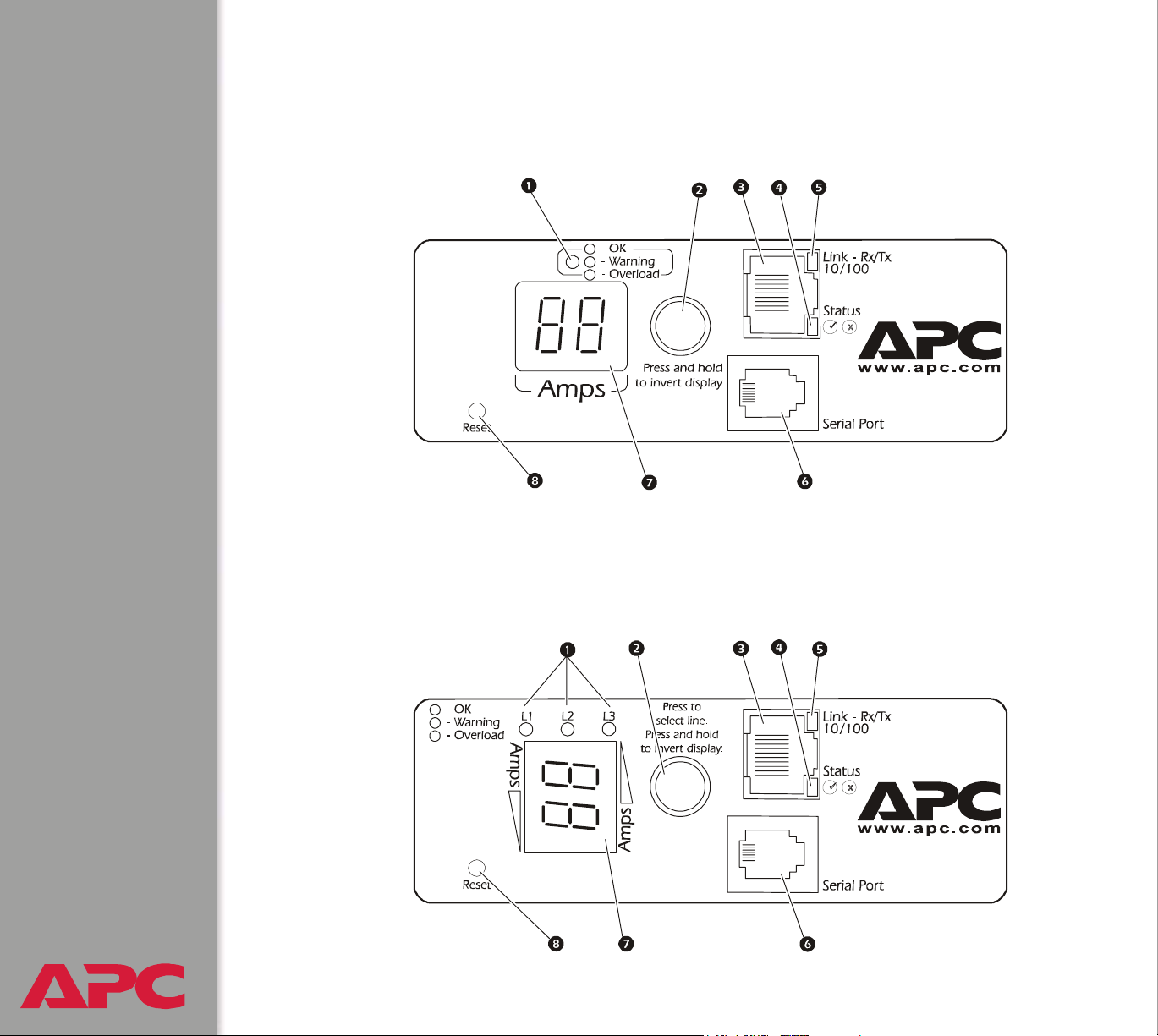
Front Panel
Single-phase
Three-phase
Three-phase Switched Rack PDUs have one of the following two front
panels:
USER’S GUIDE
Switched Rack PDU
®
10
Page 14

Item Function
Load Indicator LED Identifies overload and warning conditions for the
displayed phase or bank. See Load indicator LED.
Input Selector On 3-phase models, press the input selector to
monitor the current of the next phase or bank.
For either 1- or 3-phase units, press and hold the
input selector to display the IP address of the Rack
PDU or to invert the display. At five seconds, the IP
address is displayed; at ten seconds the displayed
numbers invert.
10/100 Base-T Connector Connects the Rack PDU to the network.
Status LED See Status LED.
Link-RX/TX LED See Link-RX/TX (10/100) LED.
RJ-12 Serial Port Connects the Rack PDU to a terminal emulator
program for local access to the control console.
(Use the supplied serial cable 940-0144.)
USER’S GUIDE
Switched Rack PDU
®
11
Page 15

Item Function
Digital Display Displays the current (amps) for the phase or bank
indicated by the illuminated Load Indicator LED. On
3-phase units, the Digital Display will cycle through
the phases or banks, displaying the current for each
for 3 seconds.
If an internal communication failure or power supply
failure occurs (for either a 1- or 3-phase model), the
Digital Display displays Er, which you can clear by
pressing the input selector.
Reset Button Resets the Rack PDU without affecting the outlet
status.
Link-RX/TX (10/100) LED
This LED indicates the network status.
Condition Description
Off The device that connects the Rack PDU to the network is off or
not operating correctly.
Flashing Green The Rack PDU is receiving data packets from the network at 10
Megabits per second (Mbps).
Flashing Orange The Rack PDU is receiving data packets from the network at
100 Megabits per second (Mbps).
Solid Green or
Orange
USER’S GUIDE
Switched Rack PDU
®
The Rack PDU is not receiving any network traffic.
12
Page 16

Status LED
This LED indicates the network status of the Rack PDU.
Condition Description
Off The Rack PDU has no power.
Solid Green The Rack PDU has valid TCP/IP settings.
Flashing Green The Rack PDU does not have valid TCP/IP settings.
†
Solid Orange
Flashing Orange The Rack PDU is making BOOTP requests.
Flashing Orange and
Green (alternating)
† If you do not use a BOOTP or DHCP server, see the Installation and Quick Start manual
provided in PDF on the Utility CD that came with your Rack PDU and as a printed manual to
configure the TCP/IP settings.
A hardware failure has been detected in the Rack PDU. Contact
APC Worldwide Customer Support.
The Rack PDU is making DHCP requests.
Load indicator LED
The load indicator LED identifies overload and warning conditions for the
displayed phase or bank.
Condition Description
Solid Green The current of the displayed phase or bank is below the
Current Overload threshold.
Yellow The displayed phase or bank is in a Near Overload Warning
condition. The current is above the Near Overload Warning
threshold.
USER’S GUIDE
Switched Rack PDU
®
Red The displayed phase or bank is in an Overload condition. The
current is above the Overload Alarm threshold.
13
Page 17

Watchdog Features
Overview
To detect internal problems and recover from unanticipated inputs, the Rack
PDU uses internal, system-wide watchdog mechanisms. When it restarts
itself to recover from an internal problem, a System: Warmstart event is
recorded in the event log.
Network interface watchdog mechanism
The Rack PDU implements internal watchdog mechanisms to protect itself
from becoming inaccessible over the network. For example, if the Rack
PDU does not receive any network traffic for 9.5 minutes (either direct
traffic, such as SNMP, or broadcast traffic, such as an Address Resolution
Protocol [ARP] request), it assumes that there is a problem with its network
interface and restarts itself.
Resetting the network timer
To ensure that the Rack PDU does not restart if the network is quiet for 9.5
minutes, the Rack PDU attempts to contact the Default Gateway every 4.5
minutes. If the gateway is present, it responds to the Rack PDU, and that
response restarts the 9.5-minute timer. If your application does not require
or have a gateway, specify the IP address of a computer that is running on
the network most of the time and is on the same subnet. The network traffic
of that computer will restart the 9.5-minute timer frequently enough to
prevent the Rack PDU from restarting.
USER’S GUIDE
Switched Rack PDU
®
14
Page 18

Control Console
How to Log On
Overview
You can use either a local (serial) connection, or a remote (Telnet or SSH)
connection to access the control console.
Use case-sensitive User Name and Password entries to log on (by default,
apc and apc for an Administrator, or device and apc for a Device
Manager). A Read-Only User has no access to the control console.
If you cannot remember your user name or password, see
How to Recover From a Lost Password.
There is no default password for Outlet User accounts. (An Administrator
must define the password and other account characteristics for an Outlet
User.)
See Outlet User Manager.
USER’S GUIDE
Switched Rack PDU
®
15
Page 19

Remote access to the control console
You can access the control console through Telnet or Secure SHell (SSH),
depending on which is enabled. (An Administrator can enable these access
methods through the Telnet/SSH option of the Network menu.) By default,
Telnet is enabled. Enabling SSH automatically disables Telnet.
Telnet for basic access. Telnet provides the basic security of
authentication by user name and password, but not the high-security
benefits of encryption. To use Telnet to access the control console from any
computer on the same subnet:
1. At a command prompt, type telnet and the System IP address for
the Rack PDU (when the PDU uses the default Telnet port of 23), and
then press
telnet 139.225.6.133
ENTER. For example:
If the PDU uses a non-default port number (between 5000
and 32768), you need to include a colon or a space
(depending on your Telnet client) after the IP address and
then enter the port number.
2. Enter the user name and password (by default, apc and apc for an
Administrator, or device and apc for a Device Manager).
SSH for high-security access. If you use the high security of SSL for the
Web interface, use Secure SHell (SSH) for access to the control console.
SSH encrypts user names, passwords and transmitted data.
The interface, user accounts, and user access rights are the same whether
you access the control console through SSH or Telnet, but to use SSH, you
must first configure SSH and have an SSH client program installed on your
USER’S GUIDE
Switched Rack PDU
®
computer.
16
Page 20

Local access to the control console
You can use a local computer that connects to the Rack PDU through the
serial port on the front panel of the unit.
1. Select a serial port at the local computer, and disable any service
which uses that port.
2. Use the supplied serial cable (940-0144) to connect the selected port
to the serial port on the front panel of the Rack PDU.
3. Run a terminal program (such as HyperTerminal) and configure the
selected port for 9600 bps, 8 data bits, no parity, 1 stop bit, and no flow
control. Save the changes.
4. Press
prompt.
ENTER, repeatedly if necessary, to display the User Name
USER’S GUIDE
Switched Rack PDU
®
17
Page 21

Main Screen
Example main screen
The main screen that is displayed when you log on to the control console of
a Rack PDU:
User Name : apc
Password : ***
American Power Conversion Network Management Card AOS v2.6.4
(c) Copyright 200 2 Al l Ri gh ts Res er ve d Rack PDU APP v2.6.6
------------------------------------------------------------------------------Name : MS3 Test Unit Date : 6/25/2004
Contact : Bill Cooper Time : 10:16:58
Location : Testing Lab User : Administrator
Up Time : 0 Days 0 Hours 43 Minutes Stat : P+ N+ A+
Switched Rack PDU : Co mm un ic at io n Es ta bl is he d
------- Control Console -------------------------------------------------------
1- Device Manager
2- Network
3- System
4- Logout
<ESC>- Main Menu, <ENTER>- Refresh, <CTRL-L>- Event Log
USER’S GUIDE
Switched Rack PDU
®
18
Page 22

Information and status fields
Main screen information fields.
• Two fields identify the APC operating system (AOS) and application
(APP) firmware versions. The application firmware uses a name that
identifies the type of device that connects to the network. In the
Example main screen, the application firmware for the Rack PDU is
displayed.
Network Management Card AOS v2.6.4
Rack PDU APP v2.6.6
• Three fields identify the system Name, Contact, and Location values.
Name : MS3 Test Unit
Contact : Bill Cooper
Location : Testing Lab
To set the Name, Contact, and Location values, see System
Menu.
•An Up Time field reports how long the Rack PDU has been running
since it was last reset or since power was applied.
Up Time : 0 Days 0 Hours 43 Minutes
• Two fields identify when you logged on, by Date and Time.
Date : 6/25/2004
Time : 10:16:58
•A User field identifies whether you logged on as Administrator, Device
Manager, or Outlet User.
User : Administrator
USER’S GUIDE
Switched Rack PDU
®
19
Page 23
Main screen status fields.
•A Stat field reports the Rack PDU status.
Stat : P+ N+ A+
P+ The APC operating system (AOS) is functioning properly.
N+ The network is functioning properly.
N? A BOOTP request cycle is in progress.
N– The Rack PDU failed to connect to the network.
N! Another device is using the IP address of the Rack PDU.
A+ The application is functioning properly.
A– The application has a bad checksum.
A? The application is initializing.
A! The application is not compatible with the AOS.
If the AOS status is not P+, contact APC Worldwide Customer
Support, even if you can still access the Rack PDU.
• A Rack PDU model and name field reports the status of the Rack PDU.
For example:
Switched Rack PDU: Communication Established
USER’S GUIDE
Switched Rack PDU
®
20
Page 24

Control Console Menus
Menu structure
The menus in the control console list options by number and name. To use
an option, type the corresponding number and press
any on-screen instructions.
For menus that allow you to change a setting, you must use the Accept
Changes option to save the changes you made.
While in a menu, you can also do the following:
ENTER, then follow
• Type ? and press
the menu has help available).
• Press
• Press
current menu.
• Press
• Press
Manager only).
ENTER to refresh the menu.
ESC to go back to the menu from which you accessed the
CTRL-C to return to the main (control console) menu.
CTRL-L to access the event log (Administrator and Device
For information about the event log, see Event-Related
Menus.
ENTER to access brief menu option descriptions (if
USER’S GUIDE
Switched Rack PDU
®
21
Page 25

Main menu
The main control console menu has options that provide access to the
management features of the control console:
1- Device Manager
2- Network
3- System
4- Logout
s
When you log on as Device Manager or as an Outlet User,
you will not have access to the Network or System menus.
Device Manager option
This option accesses the Device Manager menu. Select the components
you want to manage from this menu. To do any of the following tasks, see
Switched Rack PDU Settings:
1- Phase/Bank Monitor/Configuration
2- Phase/Bank Outlet Restriction Configuration
3- Outlet Control/Configuration
4- Power Supply Status
Option 4 is not available to outlet users.
USER’S GUIDE
Switched Rack PDU
®
22
Page 26

Network option
To do any of the following tasks, see Network Menu:
• Configure the TCP/IP settings for the Rack PDU or, when the Rack
PDU will obtain its TCP/IP settings from a server, configure the settings
for the type of server (DHCP or BOOTP) to be used.
• Use the Ping utility.
• Define settings that affect the FTP, Telnet, Web interface and SSL,
SNMP, e-mail, DNS, and Syslog features of the Rack PDU.
System option
To do any of the following tasks, see System Menu:
• Control Administrator, Device Manager, and Outlet User access
• Define the system Name, Contact, and Location values
• Set the date and time used by the Rack PDU
• Restart the Rack PDU
• Reset control console settings to their default values
• Access system information about the Rack PDU
USER’S GUIDE
Switched Rack PDU
®
23
Page 27
Web Interface
How to Log On
Overview
You can use the DNS name or System IP address of the Switched Rack
PDU for the URL address of the Web interface.
If you are using HTTPS (SSL/TSL) as your access protocol, your
login credentials are compared with information in a server
certificate. If the certificate was created with the APC Security
Wizard, when you log on you must use the same identifier for the
Rack PDU as you specified for the common name in the certificate
(either the IP address or the DNS name).
Use your case-sensitive user name and password settings to log on. The
default user name differs by account type:
• apc for an Administrator
• device for a Device Manager
• readonly for a Read Only User
The default password is apc for all three account types.
There is no default password for Outlet User accounts. (An Administrator
must define the password and other account characteristics for an Outlet
User.)
See Outlet User Manager.
USER’S GUIDE
Switched Rack PDU
®
24
Page 28

See Web/SSL (Web/SSL/TLS in the control console) to select, enable,
and disable the protocols that control access to the Web interface and
to define the Web-server ports for the protocols.
For information about the Web page that appears when you log on
to the Web interface, see Summary Page.
Supported Web browsers
As your browser, you can use Microsoft® Internet Explorer (IE) 5.0 (and
higher) or Netscape
Rack PDU through its Web interface. Other commonly available browsers
also may work but have not been fully tested by APC.
Data verification, the event log, and the data log require that you enable the
following for your Web browser:
• JavaScript
•Java
®
4.0.8 (and higher, except Netscape 6.x) to access the
• Cookies
In addition, the Rack PDU cannot work with a proxy server. Therefore,
before you can use a Web browser to access its Web interface, you must
do one of the following:
• Configure the Web browser to disable the use of a proxy server for the
Rack PDU.
• Configure the proxy server so that it does not proxy the specific IP
address of the Rack PDU.
USER’S GUIDE
Switched Rack PDU
®
25
Page 29

URL address formats
Type the Rack PDU’s DNS name or IP address in the Web browser’s URL
address field and press
server port in Internet Explorer, http:// or https:// is automatically
added by the browser.
If the error “You are not authorized to view this page” occurs
(Internet Explorer only), someone is logged onto the Web interface
or control console. If the error “No Response” (Netscape) or “This
page cannot be displayed” (Internet Explorer) occurs, Web access
may be disabled, or the Rack PDU may use a non-default Webserver port that you did not specify correctly in the address. (For
Internet Explorer, you must type http:// or https://as part of
the address when any port other than 80 is used.)
For more information, see Port assignments.
ENTER. Except when you specify a non-default web
• For a DNS name of Web1, the entry would be one of the following:
–http://Web1 if HTTP is your access mode
–https://Web1 if HTTPS (SSL/TLS) is your access mode
• For a System IP address of 139.225.6.133, when the Rack PDU uses the
default port (80) at the Web server, the entry would be one of the following:
–http://139.225.6.133 if HTTP is your access mode
–https//139.225.6.133 if HTTPS (SSL/TLS) is your access mode
• For a System IP address of 139.225.6.133, when the Rack PDU uses
a non-default port (5000, in this example) at the Web server, the entry
would be one of the following:
USER’S GUIDE
Switched Rack PDU
®
–http://139.225.6.133:5000 if HTTP is your access mode
–https://139.225.6.133:5000 if HTTPS (SSL/TLS) is your
access mode
26
Page 30

Summary Page
When you log on to the Web interface at the Switched Rack PDU, the status
view is at the right side of the screen, the quick status tab is at the upper
right, and the navigation menu is at the left.
Status
The Status view has three sections:
• The Device Status section reports any active alarm or warning
conditions and displays the load for each phase or bank, including a
graphic representation of the load thresholds.
• The Outlet Status section shows the number, phase or bank (for 3phase models), state (on, off), and name of the outlet.
•The Switched Rack PDU Parameters section shows the following:
– The Name, Contact, and Location information for the Rack PDU
– The date and time you logged on
– The Type of User (Administrator, Device Manager, Read Only
User, or Outlet User)
– The time (Up Time) the Rack PDU has been running continuously
since it was last reset or power was applied
– The rating of the Rack PDU (1- or 3-phase, and the maximum
number of amps per phase or bank)
USER’S GUIDE
Switched Rack PDU
®
27
Page 31

Quick status tab
The quick status tab is displayed at the upper right on every page in the
Web interface. The tab shows active alarms and warnings and a link to the
online help.
Click the help icon to access the online help for the displayed page.
Click the green “device operating normally” icon to return to the status
screen where the current for each phase or bank is displayed.
Click the warning icon to return to the status screen where active warnings
are displayed. Put the mouse cursor on the icon to view details of the
warning.
Click the alarm icon to return to the status screen where active alarms are
displayed. Put the mouse cursor on the icon to display details of the alarm.
USER’S GUIDE
Switched Rack PDU
®
28
Page 32

Navigation Menu
Overview
On the Web interface, the navigation menu (left frame) has the following
elements:
• IP address of the Rack PDU
• Menus to manage the Rack PDU and its components:
– Switched Rack PDU menu with Configuration and Scheduling as
options
– Outlets menu with Control, Configuration, and Outlet Groups as
options
• Menus to manage the event log, data log, network connection, and
system parameters:
– Events menu
– Data menu
– Network menu
– System menu
When you log on as a Device Manager or Read-Only User, the
Network and System menus are not displayed. Options to
make any changes are not available for the Read-Only User.
When you log on as an Outlet User, the Switched Rack PDU,
Events, Network, and System menus are not displayed.
• Logout option
• Help menu
• Links menu
USER’S GUIDE
Switched Rack PDU
®
29
Page 33

Selecting a menu to perform a task
• To do the following, see Switched Rack PDU Settings:
– Configure the overload and low load thresholds for each phase or
bank.
– Configure the Overload Outlet Restriction for each phase or bank.
– Set the Name, Location, and Coldstart Delay for the Rack PDU.
• To do the following, see Outlet Settings for Outlets and Outlet Groups:
– Apply power to and remove power from the outlets.
–Set Power On Delay, Power Off Delay, and Reboot Duration for
the outlets.
– Set the names and associated links for the outlets.
– Create, enable, and use synchronized outlet groups.
• To do the following, see Event-Related Menus:
– Access the event log.
– Configure the actions to be taken based on the severity level of an
event.
– Configure SNMP Trap Receiver settings for sending event-based
traps.
– Define who will receive e-mail notifications and Syslog messages for
events.
– Test e-mail settings.
• To do the following, see Data Menu (Web Interface Only):
– Access the data log.
– Define the log interval (how often data will be sampled and
recorded) for the data log.
USER’S GUIDE
Switched Rack PDU
®
30
Page 34

• To do the following, see Network Menu:
– Configure new TCP/IP settings for the Rack PDU.
– Identify the Domain Name System (DNS) Server, test its network
connection, and enable or disable DNS Reverse Lookup Event
Logging (which logs the domain name of the device associated with
each event).
– Define settings for FTP, Telnet, SSH, the Web interface, SNMP,
e-mail, and SSL/TLS.
– Configure the Rack PDU’s Syslog message feature.
• To do the following, see System Menu:
– Control Administrator and Device Manager access.
– Manage Outlet User access.
– Define the system Name, Contact, and Location values.
– Set the date and time used by the Rack PDU.
– Restart the Rack PDU.
– Reset control console settings to default settings.
– Define the URL addresses of the user links and APC logo link in the
Web interface, as described in Links menu.
Help menu
When you click Help, the Contents page for all of the online help is
displayed. However, from any Web interface pages, you can use the
question mark (?) in the quick status bar to link to the section of the online
help for that page.
The About System option of the Help menu displays information in the
following fields: Model Number, Serial Number, Hardware Revision,
Manufacture Date, MAC Address, Application Module, APC OS (AOS)
USER’S GUIDE
Switched Rack PDU
®
Module (the APC Operating System Module of the Switched Rack PDU),
and the date and time that each of the two modules were created.
31
Page 35

In the control console, the About System option, which is a
System menu option, has the Flash Type value.
Links menu
Provides three user-definable URL link options. By default, these links
access the following APC Web pages:
• APC’s Web Site accesses the APC home page.
• Testdrive Demo accesses a demonstration page where you can use
samples of APC Web-enabled products.
• APC Monitoring accesses the “APC Remote Monitoring Service”
page about pay-for-monitoring services available from APC.
To redefine these links so that they point to other URLs:
1. Click on Links in the System menu.
2. Define any new names for User Links.
3. Define any new URL addresses that you want User Links to access.
Only HTTP links may be defined.
4. Click Apply.
The link associated with the APC logo is also definable.
USER’S GUIDE
Switched Rack PDU
®
32
Page 36

Device and Outlet Management Menus
How to Configure and Control Outlet Groups
Outlet group terminology
An outlet group consists of outlets that are logically linked together on the
same Switched Rack PDU. Outlets that are in an outlet group turn on, turn
off, and reboot in a synchronized manner, i.e., within a one-second interval
under normal conditions:
•A local outlet group consists of two or more outlets on a Switched Rack
PDU. Only the outlets in that group are synchronized.
•A global outlet group consists of one or more outlets on a Switched Rack
PDU. One outlet is configured as a global outlet, which logically links the
outlet group to outlet groups on up to three other Switched Rack PDUs.
All outlets in the linked global outlet groups are synchronized.
– For global outlet groups, the initiator outlet group is the group that
issued the action
– For global outlet groups, a follower outlet group is any other outlet
group that is synchronized with the initiator outlet group.
When you apply an outlet control action to outlets that are members of an
outlet group, the outlets are synchronized as follows:
• For a global outlet group, use the delay periods and reboot duration
configured for the global outlet of the initiator outlet group.
• For a local outlet group, the outlets use the delay periods and reboot
duration of the lowest-numbered outlet in the group.
USER’S GUIDE
Switched Rack PDU
®
33
Page 37

Purpose and benefits of outlet groups
By using groups of synchronized outlets on Switched Rack PDUs, you can
ensure that outlets turn on, turn off, and reboot in a synchronized manner.
Synchronizing control group actions through outlet groups provides the
following benefits.
• Synchronized shutdown and startup of the power supplies of dualcorded servers avoids erroneous reporting of power supply failures
during a planned system shutdown or reboot.
• Synchronizing outlets by using outlet groups provides more precise
shutdown and restart timing than relying on the delay periods of
individual outlets.
• A global outlet is visible to the user interfaces of the Switched Rack
PDUs to which it is linked.
Under normal conditions all outlets in outlet groups affected by a
control action will perform that action within a one-second interval.
USER’S GUIDE
Switched Rack PDU
®
34
Page 38

System requirements for outlet groups
To set up and use synchronized outlet control groups:
• You need a 10/100Base-T TCP/IP network, with an Ethernet hub or
switch that has a power source not shared by the computers or other
devices being synchronized.
• If outlets groups are to be synchronized across multiple Switched Rack
PDUs, those Switched Rack PDUs must meet the following
requirements:
– They must be on the same subnet.
– They must use firmware that has the same version number, which
must be 2.6.1 or higher for both the APC Operating System (AOS)
module and the Application module. As later firmware revisions
become available, be sure to upgrade each Switched Rack PDU.
• You need a computer that can initiate synchronized control operations
through the Web interface or control console of the Switched Rack
PDUs or through SNMP.
• You must ensure that Multicast network traffic is allowed for the
selected Multicast IP address by each switch that connects the
Switched Rack PDUs.
USER’S GUIDE
Switched Rack PDU
®
35
Page 39

Rules for configuring outlet groups
For a system that uses outlet groups, the following rules apply:
• A Switched Rack PDU can have more than one outlet group, but an
outlet can belong to only one outlet group.
• A local outlet group, which has no global outlet, must consist of two or
more outlets.
• You can synchronize a global outlet group on one Switched Rack PDU
with a global outlet group on each of three other Switched Rack PDUs.
– In a global outlet group, you can designate only one outlet to be a
global outlet, linking to outlet groups on other Switched Rack PDUs
for the purpose of synchronization. That global outlet can be the
only outlet in its group, or the group can consist of multiple outlets.
– For outlet groups on Switched Rack PDUs to be linked for
synchronization, those Switched Rack PDUs must have the same
Device Multicast Name and Device Multicast Address and be
running the same version of Switched Rack PDU firmware.
– A global outlet of one outlet group must have the same physical outlet
number as the global outlet of any other outlet group to which it links.
– Even if InfraStruXure Manager is not used with your system, you
must enable the ISX Protocol for each Switched Rack PDU to link
global outlet groups across Switched Rack PDUs.
To enable the ISX Protocol, see ISX Protocol (control
console only).
• To create and configure outlet groups, you must use the Web interface
or export configuration file (.ini file) settings from a configured Switched
Rack PDU. The control console lets you display whether an outlet is a
USER’S GUIDE
Switched Rack PDU
®
member of an outlet group and to apply control actions to an outlet
group, but does not let you set up or configure an outlet group.
36
Page 40

How to enable outlet groups
From the Outlets menu in the Web interface, select Outlet Groups,
configure the following parameters, and click Apply.
Enable creation of outlet groups.
Parameter Description
Device Level Outlet Group To create an outlet group, you must enable this
parameter. It is disabled by default.
Enable support for global outlet groups (linked groups).
Parameter Description
Multicast Name To link outlet groups on multiple Switched Rack PDUs, you must
Multicast IP
define the same Multicast name and Multicast IP address on each
of those Rack PDUs.
OTE: A Maximum of four devices can be configured with the
N
same Multicast name and Multicast IP address.
How to create a local outlet group (Web interface)
1. From the Outlets menu in the Web interface, select Outlet Groups.
2. Make sure outlet groups are enabled.
See Enable creation of outlet groups.
3. Click Create Local Outlet Group.
4. Under Configure Local Outlet Group, select each outlet that will be in
the group. You must select at least two outlets.
USER’S GUIDE
Switched Rack PDU
®
37
Page 41

How to create multiple global outlet groups (Web interface)
To set up multiple global outlet groups that link to outlet groups on other
Switched Rack PDUs:
1. From the Outlets menu in the Web interface, select Outlet Groups.
2. Make sure outlet groups are enabled and that the Multicast parameters
(name and IP address) are the same for all Rack PDUs to be linked.
See How to enable outlet groups.
3. Click Create Global Outlet Groups.
4. For each global outlet group you want to create, select an outlet by
clicking on its check-box. Then click Apply. For example, select five
outlets to create five outlet groups, each consisting of one global outlet.
5. To add outlets to any of the global outlet groups you created, see How
to edit or delete an outlet group.
How to edit or delete an outlet group
1. From the Outlets menu in the Web interface, select Outlet Groups.
2. Under Configured Outlet Groups, click on the number or name of the
outlet group to edit or delete.
3. When editing an outlet group you can do any of the following:
– Rename the outlet group.
– Add or remove outlets by clicking the check-boxes to mark or
unmark them.
You cannot remove an outlet from an outlet group that
contains only two outlets unless the remaining outlet is a
USER’S GUIDE
Switched Rack PDU
®
4. To delete the outlet group, click Delete Outlet Group.
global outlet.
38
Page 42
Typical outlet group configurations
The following configuration shows two Switched Rack PDUs, each with
eight outlet groups. Each outlet group consists of a single global outlet.
Each outlet group
group
power cord of a dual-corded server
first Switched Rack PDU, and its other cord is connected to the
corresponding outlet on the second Switched Rack PDU, ensuring that
output power from both power sources to the server will turn on or off in a
synchronized manner in response to an outlet control action.
in the same location on the second Switched Rack PDU. One
on the first Switched Rack PDU is linked to the outlet
is connected to each outlet on the
USER’S GUIDE
Switched Rack PDU
®
39
Page 43

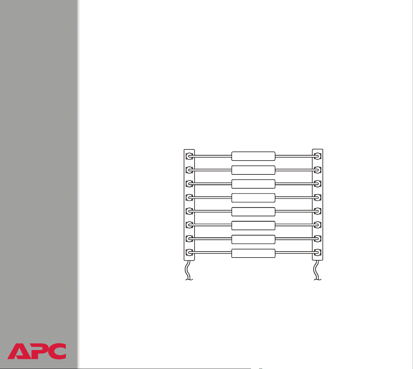
The following configuration shows three sets of synchronized outlets.
Global outlets are shown in black. Outlet groups are enclosed in red
rectangles.
These four global outlet groups synchronize a total of 19 outlets.
These two global outlet groups synchronize 6 outlets, 2 in one group and 4 in the
other.
This local outlet group synchronizes 3 outlets on the same Switched Rack PDU.
USER’S GUIDE
Switched Rack PDU
®
40
Page 44

Verify your setup and configuration for global outlet groups
To ensure that your setup meets all system requirements for outlet group
and that you have configured the outlet groups correctly, select Outlet
Groups from the Outlets menu in the Web interface to view the groups and
their connections:
• The Configured Outlet Groups section displays the following:
– All configured outlet groups on the current Switched Rack PDU.
– The outlets in each group by outlet number.
– Any outlet groups on other Switched Rack PDUs with which a global
outlet group is synchronized. Each Switched Rack PDU is identified
by its IP address, and each global outlet is displayed in bold text.
• The Global Outlet Overview section displays the following:
– The IP address of the current Switched Rack PDU.
– The IP address of any Switched Rack PDUs that contain global
outlets that are available to be synchronized with outlet groups on
other Switched Rack PDUs.
– All global outlets configured on the Switched Rack PDUs listed,
regardless of whether they are synchronized with outlet groups on
the current Switched Rack PDU.
USER’S GUIDE
Switched Rack PDU
®
41
Page 45

Outlet Settings for Outlets and Outlet Groups
How to initiate a control action
If you apply an outlet control action to outlets or outlet groups, the
following delays are used for the action:
• For an individual outlet (not in an outlet group), the action uses
the delay periods and reboot duration configured for that outlet.
• For a global outlet group, the action uses the delay periods
and reboot duration configured for the global outlet.
• For a local outlet group, the action uses the delay periods
configured for the lowest-numbered outlet in the group.
Web interface. To control the outlets on your Switched Rack PDU
1. Select Outlets, and then Control on the navigation menu.
2. Mark the check-boxes for each individual outlet or outlet group to
control, or select the All Outlets check-box.
3. Select a Control Action from the list, and click Next >>. On the
confirmation page that explains the action, choose to execute or cancel it.
Control Console. Select Outlet Control/Configuration from the Device
Manager menu to display a list of outlets. For each outlet, the list indicates
whether it is a member of an outlet group.
1. Choose either or the following:
– To control one outlet and the outlet group, if any, to which it belongs,
select the number of the outlet, and then select Control Outlet.
– To control all outlets, select Master Control/Configuration, and
then Control of ALL Outlets.
USER’S GUIDE
Switched Rack PDU
®
2. Select a control action.
3. On the confirmation screen that describes the action to be executed,
type Yes at the prompt to perform the action.
42
Page 46

Control actions you can select.
t
Option Description
No Action (Web interface only) Do nothing.
On Immediate Apply power to the selected outlets.
On Delayed Apply power to each selected outlet according to its
value for Power On Delay.
Off Immediate Remove power from the selected outlets.
Off Delayed Remove power from each selected outlet according to
its value for Power Off Delay.
Reboot Immediate Remove power from each selected outlet. Then apply
power to each of these outlets according to its value
for Reboot Duration.
Reboot Delayed Remove power from each selected outlet according to
its value for Power Off Delay. Wait until all outlets are
off (the highest value for Reboot Duration), and then
Cancel Pending Commands
(Web Interface)
Cancel (control console)
apply power to each outlet according to its value for
Power On Delay.
Cancel all commands pending for the selected outlets
and keep them in their present state.
N
OTE: For global outlet groups, you can cancel a
command only from the interface of the initiator outlet
group. The action will cancel the command for the
initiator outlet group and all follower outlet groups.
†
†
†
†
† If a local outlet group is selected, only the configured delays and reboot duration of the lowest-
numbered outlet of the group are used. If a global outlet group is selected, only the configured
delays and reboot duration of the global outlet are used.
USER’S GUIDE
Switched Rack PDU
®
43
Page 47

How to configure outlet settings and outlet name
Settings that you can configure. The following settings are available in
both the Web interface and control console unless otherwise indicated:
Setting Description
Power On Delay Set the number of seconds that the Rack PDU waits after a
command is issued before applying power to an outlet.
OTE: To configure an outlet to remain off at all times, check the
N
Never check box next to Power On Delay in the Web interface, or
configure a value of
Power Off Delay Set the number of seconds that the Rack PDU waits after a
command is issued before removing power from an outlet.
N
OTE: To configure an outlet to remain on at all times, check the
Never check box next to Power Off Delay in the Web interface, or
configure a value of
Reboot Duration Set the number of seconds an outlet remains off before restarting.
–1 for Power On Delay in the control console.
–1 for Power Off Delay in the control console.
Name (Web
interface)
Outlet Name
(control console)
Link (Web
interface)
USER’S GUIDE
Switched Rack PDU
®
Set the name for one or more outlets. The name is displayed next
to the outlet number on status screens.
Define an HTTP or HTTPS link to a Web site or IP address.
• http://www.apcc.com links the outlet to the home page of the
APC Web site.
• http://158.205.7.201 links the outlet to the Web interface of the
Switched Rack PDU at the IP address 158.205.7.201, enabling
you to log on to that interface (if you have the appropriate access).
OTE: If the outlet is a member of an outlet group, the only link that
N
is used is the link configured for the global outlet or (for a local
outlet group) the link configured for the lowest-numbered outlet of a
local outlet group. You can configure a link for another outlet in an
outlet group, but that link will be available to use only when that
outlet is no longer a member of an outlet group.
44
Page 48

Web Interface. To configure the outlet settings or outlet names, select
Configuration on the Outlets menu, and click the Configure button in the
Outlet Settings section or in the Outlet Name Configuration section.
• Configure outlet settings in the top section of the next screen:
– Select the check-boxes next to the numbers of the outlets you want
to modify, or select the All Outlets check-box.
– Enter values for Power On Delay, Power Off Delay, or Reboot
Duration, and click the Apply button immediately below the list.
• Configure outlet names and links in the bottom section of the next screen:
– Select the check boxes next to the numbers of the outlets you want
to modify, or select the All Outlets check-box.
– Enter values for Name and Link, and click the Apply button
immediately below the list.
Control Console. To configure the outlet settings and outlet name:
1. Select Outlet Control/Configuration from the Device Manager
menu.
2. Choose the number of the outlet you want to control, and press
3. Choose Configure Outlet to display and change the values for Outlet
Name, Power On Delay, Power Off Delay, and Reboot Duration.
USER’S GUIDE
Switched Rack PDU
®
45
ENTER.
Page 49

Switched Rack PDU Settings
Configure Load Thresholds
Web interface.
1. Select Switched Rack PDU from the navigation menu.
2. Click Configure in the Load Management section.
3. Set Overload Alarm Threshold, Near Overload Warning Threshold,
Low Load Warning Threshold, and Overload Outlet Restrictions
for each phase or bank.
4. Click Apply in that section to set the selected values.
Control console.
1. From the Device Manager menu, select Phase/Bank Monitor/
Configuration.
2. Select a phase or bank (for 3-phase units).
3. Select Overload Alarm Threshold (amps), Near Overload Warning
Threshold (amps), or Low Load Warning Threshold (amps).
4. Select Accept Changes.
To set the overload outlet restriction, select
on the Device manager menu. For 3-phase units, select a phase or bank to
display and change the Outlet Phase/Bank Restriction.
Setting Description
Overload Alarm
Threshold
Near Overload
Warning Threshold
USER’S GUIDE
Switched Rack PDU
®
Set the number of amps that will cause an overload of this phase
or bank.
Set the number of amps at which to generate a warning that the
Rack PDU is nearing overload of a phase or bank.
46
Outlet Restriction Configuration
Page 50

Setting Description
Low Load Warning
Threshold
Overload Outlet
Restriction
Set the low threshold, in amps, for the current drawn from this
phase or bank during normal operation. A load at or below this
level generates a warning.
Prevent users from applying power to outlets during an overload
condition. You can set the following restrictions for each outlet:
• None: You can apply power to outlets regardless of an Overload
Alarm or Near Overload Warning.
• On Warning: You cannot apply power to an outlet on the
selected phase or bank if the current for that phase or bank has
exceeded the Near Overload Warning threshold.
• On Overload: You cannot apply power to an outlet on the
selected phase or bank if the current for that phase or bank has
exceeded the Overload Alarm threshold.
How to configure Device Settings
Web interface. Select Configuration on the Switched Rack PDU menu.
Then, under Device Settings, click the Configure button and configure the
Name and Location fields for the Rack PDU, and set the Coldstart Delay.
Control console.
1. Select Outlet Control/Configuration from the Device Manager menu.
2. Select Master Control/Configuration from the displayed list.
3. Select Master Outlet Configuration from the next menu displayed.
4. Change the Name, Location, or Coldstart Delay from this menu.
USER’S GUIDE
Switched Rack PDU
®
47
Page 51

Setting Description
Name Set the name of the Rack PDU.
Location Set the location of the Rack PDU.
Coldstart Delay The time that the Switched Rack PDU delays applying power to
the outlets after AC power has been applied to the Rack PDU.
To change the Contact field (the name of the person to contact
about the Rack PDU) in addition to the Name and Location fields
in the control console, see Identification.
Power Supply Status (control console only)
Select Power Supply Status from the Device Manager menu to display
the status of the power supplies of the Switched Rack PDU.
USER’S GUIDE
Switched Rack PDU
®
48
Page 52

Scheduling Outlet Actions (Web Interface Only)
Actions you can schedule
For any outlets you select, you can schedule any of the following actions to
occur daily; at intervals of one, two, four, or eight weeks; or only once.
To configure values for Power On Delay, Power Off Delay, and
Reboot Duration for each outlet, see How to configure outlet
settings and outlet name. Although you must use the Web
interface to schedule outlet actions, you can set these values in
either the Web or control console interfaces.
For an action to be applied to an outlet group, you must have
outlet groups enabled at the beginning of the scheduled action.
For example, if Off Delayed is scheduled for 4:00 p.m., the Power
Off Delay begins at 4:00 p.m. Even if you then enable outlet
groups during that Power Off Delay before any of the outlets are
scheduled to turn off, the action will be applied only to the
individual outlet and not the outlet group.
Option Description
No Action Do nothing.
On Immediate Apply power to the selected outlets.
On Delayed Apply power to each selected outlet according to its value for Power
On Delay.
Off Immediate Remove power from the selected outlets.
† If an outlet group is selected, the configured delays and reboot duration of the lowest-
numbered outlet (for a local outlet group) or of the global outlet (for a global outlet group that
USER’S GUIDE
Switched Rack PDU
®
is initiating the action).
†
49
Page 53

Option Description
Off Delayed Remove power from each selected outlet according to its value for
Power Off Delay.
Reboot PDU
Immediate
Reboot PDU
Delayed
† If an outlet group is selected, the configured delays and reboot duration of the lowest-
numbered outlet (for a local outlet group) or of the global outlet (for a global outlet group that
is initiating the action).
Remove power from each selected outlet. Then apply power to
each of these outlets according to its value for Reboot Duration.
Remove power from each selected outlet according to its value for
Power Off Delay. Wait until all outlets are off (the highest value for
Reboot Duration), and then apply power to each outlet according
to its value for Power On Delay.
†
†
†
USER’S GUIDE
Switched Rack PDU
®
50
Page 54

How to schedule an outlet event
1. From the menus of the Web interface, select Switched Rack PDU and
then Scheduling.
2. On the Outlet Scheduling page, select how often the event will occur:
Daily, Weekly, or One-Time.
If you select Weekly, you can choose to have the event occur
once every week or once every two, four, or eight weeks.
3. On the scheduling page, in the Name of event text box, replace the default
name, Outlet Event, with a name that will identify your new event.
4. Use the drop-down lists to select the type of event and when it will occur.
The date format for one-time events is mm/dd, and the time
format for all events is hh/mm, with the two-digit hour
specified in 24-hour time.
• An event that is scheduled daily or at one of the intervals
available in the Weekly selection continues to occur at the
scheduled interval until the event is deleted or disabled.
• You can schedule a one-time event to occur only on a
date within 12 months of the date on which you perform
the scheduling. For example, on June 4, 2004, you could
schedule a one-time event on any date from the current
date until June 3, 2005.
5. Use the check-boxes to select which outlets will be affected by the
action. You can select one or more individual outlets or All Outlets.
6. Click Apply to confirm the scheduling of the event, or Clear to cancel it.
USER’S GUIDE
Switched Rack PDU
®
When you confirm the event, the summary page is re-displayed, with the
new event displayed in the list of scheduled events.
51
Page 55

How to edit, disable, enable, or delete an outlet event
1. From the menus of the Web interface, select Switched Rack PDU and
then Scheduling.
2. In the event list in the Summary section of the Outlet Scheduling
page, click on the name of the event.
3. On the Scheduled Event Details page, you can do any of the
following:
– Change details of the event, such as the name of the event, when it
is scheduled to occur, and which outlets are affected.
– Under Status of event at the bottom of the page:
• Disable the event, leaving all its details configured so that it can be
re-enabled later. A disabled event will not occur. An event is
enabled by default when you create it.
• Enable the event, if it was previously set to Disable.
• Delete the event, removing the event completely from the system.
A deleted event cannot be retrieved.
4. Click Clear at any time to cancel your changes to the event. Using
Clear cancels only the changes you made in the current editing
session.
5. When you finish making changes on this page, click Apply to confirm
the changes.
USER’S GUIDE
Switched Rack PDU
®
52
Page 56

Event-Related Menus
Introduction
Overview
The Events menu provides access to the options that you use to do the
following tasks:
• Access the event log
• Define the actions to be taken when an event occurs, based on the
severity level of that event:
– Event logging
– Syslog message notification
– SNMP trap notification
– E-mail notification
You can use only the Web interface to define which events
will use which actions, as described in Event Log and How to
Configure Individual Events.
• Define up to four SNMP trap receivers, by NMS-specific IP address or
domain name, for event notifications by SNMP traps.
• Define up to four recipients for event notifications by e-mail.
Menu options
In the Web interface, all of the events options are accessed through the
Events menu.
USER’S GUIDE
Switched Rack PDU
®
53
Page 57

In the control console, access the available events-related options as
follows:
• Use the Email option in the Network menu to define the SMTP server
and e-mail recipients.
• Use the SNMP option in the Network menu to define the SNMP trap
receivers.
• Use
For information on the following topics, use these links:
• Event Log
• Event Actions (Web Interface Only)
• Event Recipients
• E-mail Feature
• How to Configure Individual Events
CTRL-L to access the event log from any menu.
USER’S GUIDE
Switched Rack PDU
®
54
Page 58

Event Log
Overview
The Rack PDU supports event-logging for all embedded management card
application firmware modules. To record and display embedded
management card and Rack PDU events, use any of the following to view
the event log:
• Web interface
• Control console
• FTP
•SCP
USER’S GUIDE
Switched Rack PDU
®
55
Page 59

Logged events
By default, any event which causes an SNMP trap will be logged, except for
SNMP authentication failures. Additionally, the Rack PDU will log its
abnormal internal system events. However, you can use the Actions option
in the Web interface’s Events menu to disable the logging of events based
on their assigned severity level, as described in Event Actions (Web
Interface Only).
Some System (embedded management card) events do not have
a severity level. Even if you disable the event log for all severity
levels, events with no severity level will still be logged.
To access a list of the System (embedded management card) and
Switched Rack PDU (Device) events, see Event List page.
Web interface
The Log option in the Events menu accesses the event log. This log
displays all of the events that have been recorded since the log was last
deleted, in reverse chronological order. The Delete Log button clears all
events from the log.
Control console
Press CTRL-L to display all the events that have been recorded since the log
was last deleted, in reverse chronological order. Use the
scroll through the recorded events. While viewing the log, type d and press
ENTER to clear all events from the log.
.
USER’S GUIDE
Switched Rack PDU
After events are deleted, they cannot be retrieved.
®
56
SPACE BAR to
Page 60

How to use FTP or SCP to retrieve a log file
If you are using the encryption-based security protocols for your
system, use Secure CoPy (SCP) to retrieve the log file. (You
should have FTP disabled.) If you are using unencrypted
authentication methods for the security of your system, use FTP to
retrieve the log file.
See Security for information on the available protocols and
methods for setting up the type of security appropriate for your
needs.
If you have Administrator or Device Manager access, you can use SCP or
FTP to retrieve a tab-delineated event log file (event.txt) or data log file
(data.txt) that you can import into a spreadsheet application.
• The file reports all of the events or data recorded since the log was last
deleted.
• The file includes information that the event log or data log does not
display.
– The version of the file format (first field)
– The Date and Time the file was retrieved
– The Name, Contact, and Location values, and the IP address of
the Rack PDU
– The unique Event Code for each recorded event (event.txt file only)
The Rack PDU uses a 4-digit year for log entries. You may
need to select a four-digit date format in your spreadsheet
application to display all four digits of the year.
USER’S GUIDE
Switched Rack PDU
®
57
Page 61

Secure CoPy (SCP).
To use SCP to retrieve the event.txt file, use the following command:
scp username@hosthame_or_ip_address:event.txt ./event.txt
To use SCP to retrieve the data.txt file, use the following command:
scp username@hosthame_or_ip_address:data.txt ./data.txt
See Data Menu (Web Interface Only) for information about the
data log.
File Transfer Protocol (FTP).
To use FTP to retrieve the event.txt or data.txt file:
1. At a command prompt, type ftp and the IP address of the Switched
Rack PDU, and press
Network menu has been changed from its default value (21), you must
use the non-default value in the FTP command. For some FTP clients,
you must use a colon to add the port number to the end of the IP
address. For Windows FTP clients, use the following command
(including spaces):
ftp>open ip_address port_number
To use non-default port values to enhance security, see Port
assignments.
2. Use the case-sensitive User Name and Password values for either an
Administrator or a Device Manager User to log on.
– For Administrator, apc is the default for User Name and Password.
– For Device Manager, device is the default for User Name, and apc
is the default for Password.
USER’S GUIDE
Switched Rack PDU
ENTER. If the Port setting for FTP Server in the
®
58
Page 62

3. Use the get command to transmit the text version of the event or data
log to your local drive.
ftp>get event.txt
or
ftp>get data.txt
4. You can use the del command to clear the contents of the event or
data log.
ftp>del event.txt
or
ftp>del data.txt
You will not be asked to confirm the deletion.
– If you clear the data log, a Deleted Log event will be recorded in the
Event Log.
– If you clear the event log, a new event.txt file will be created to
record the Deleted Log event.
5. Type quit at the ftp> prompt to exit from FTP.
USER’S GUIDE
Switched Rack PDU
®
59
Page 63

Event Actions (Web Interface Only)
Overview
The Actions option is available only on the Web interface’s Events menu.
This option allows you to select which actions will occur for events that have
a specified severity level:
• Event Log selects which severity levels cause an event to be recorded
in the event log.
See Event log action.
• Syslog selects which severity levels cause messages to be sent to
Syslog servers to log events.
See Syslog action.
• SNMP Traps selects which severity levels cause SNMP traps to be
generated.
•
•
See SNMP traps action.
• Email selects which severity levels cause e-mail notifications to be sent.
See Email action.
Click Details to access a complete list of the System (embedded management
card) and Device (Rack PDU) events that can occur, and then edit the actions
USER’S GUIDE
Switched Rack PDU
®
that will occur for an individual event, as described in How to Configure
Individual Events. Click Hide Details to return to the Actions option.
60
Page 64

Modifying events on the Configure Event Action by Severity
Level page overrides any changes you made to individual events
on the Details page.
Severity levels
Except for some System (embedded management card) events that do not
have a severity level, events are assigned a default severity level based on
their seriousness:
• Informational: Indicates an event that requires no action, such as a
notification of a return from an abnormal condition.
• Warning: Indicates an event that may need to be addressed if the
condition continues, but does not require immediate attention.
• Severe: Indicates an event that requires immediate attention. Unless
resolved, severe Device and System events can cause incorrect
operation of the Rack PDU or its embedded management card.
Event log action
You can disable the recording of events in the event log. By default, all
events are recorded, even events that have no severity level assigned.
Even if you disable the event log action for all severity levels,
System (embedded management card) events that have no
severity level assigned will still be logged.
For more information about this log, see Event Log.
USER’S GUIDE
Switched Rack PDU
®
61
Page 65

Syslog action
By default, the Syslog action is enabled for all events that have a severity
level. However, before you can use this feature to send Syslog messages
when events occur, you must configure it.
See Syslog.
SNMP traps action
By default, the SNMP Traps action is enabled for all events that have a
severity level assigned. However, before you can use SNMP traps for event
notifications, you must identify the NMSs (by their IP addresses or domain
names) that will receive the traps.
To define up to four NMSs as trap receivers, see Event Recipients.
Email action
By default, the Email action is enabled for all events that have a severity
level assigned. However, before you can use e-mail for event notifications,
you must define the e-mail recipients.
See E-mail Feature.
USER’S GUIDE
Switched Rack PDU
®
62
Page 66

Event Recipients
Overview
The Web interface and control console both have options that allow you to
define up to four trap receivers and up to four e-mail addresses to be used
when an event occurs that has SNMP traps or e-mail enabled.
See Event Actions (Web Interface Only).
Trap Receiver settings
To access the Trap Receiver settings that allow you to define which NMSs
will receive traps:
• In the Web interface, use the Recipients option in the Events menu.
• In the control console, use the SNMP option in the Network menu.
Item Definition
Community Name This setting defines the password (maximum of 15
characters) used when traps are sent to the NMS
identified by the Receiver NMS IP/Domain Name setting.
Receiver NMS IP/Domain
Name
Generation (Web interface)
Trap Generation (control
console)
Authentication Traps Enables or disables the sending of authentication traps to
USER’S GUIDE
Switched Rack PDU
®
Identifies by IP address or domain name the NMS that will
receive traps. If this setting is 0.0.0.0 (the default value),
traps will not be sent to any NMS.
Enables (by default) or disables the sending of any traps
to the NMS identified by the Receiver NMS IP/Domain
Name setting.
the NMS identified by the Receiver NMS IP/Domain
Name setting.
63
Page 67

E-mail Feature
Overview
You can use the Simple Mail Transfer Protocol (SMTP) to send e-mail to up
to four recipients when an event occurs.
To use the e-mail feature, you must define the following settings:
• The IP addresses of the primary and secondary Domain Name System
(DNS) servers
See DNS servers.
• The DNS name of the SMTP server and the From Address setting for
SMTP
See SMTP settings.
• The e-mail addresses for a maximum of four recipients.
See Email Recipients.
You can use the To Address setting of the Email Recipients
option to send e-mail to a text-based pager.
USER’S GUIDE
Switched Rack PDU
®
64
Page 68

DNS servers
The Rack PDU cannot send any e-mail messages unless the IP address of
the primary DNS server is defined.
See DNS.
The Rack PDU will wait a maximum of 15 seconds for a response from the
primary or (if specified) the secondary DNS server. If the Rack PDU does
not receive a response within that time, e-mail cannot be sent. Therefore,
use DNS servers that are on the same segment as the Rack PDU or on a
nearby segment (but not across a WAN).
Once you define the IP addresses of the DNS servers, verify that DNS is
working correctly. Enter the DNS name of a computer on your network to
test whether you can look up the IP address for that DNS name.
SMTP settings
The Email option in the Network menu accesses the following settings:
Setting Description
SMTP Server Defines the SMTP server by its DNS name.
OTE: This definition is required only when the SMTP Server option
N
(see Email Recipients) is set to Local.
From Address Defines the contents of the From field in the e-mail messages sent
by the Rack PDU.
OTE: The SMTP server’s configuration may require that you use a
N
valid user account on the server for this setting. See the server’s
documentation for more information.
USER’S GUIDE
Switched Rack PDU
Email Recipients
®
65
Page 69

In the Web interface, use the Recipients option in the Events menu or the
Configure the Email recipients link in the “Email Configuration” page to
identify up to four e-mail recipients. Use the Email Test option to send a
test message to a configured recipient.
In the control console, use the Email option in the Network menu to access
the e-mail recipient settings.
Setting Description
To Address Defines the user and domain names of the recipient.
• To bypass the DNS lookup of the mail server’s IP address, use the IP
address in brackets instead of the e-mail domain name. For example,
use jsmith@[xxx.xxx.xxx.xxx] instead of jsmith@company.com. This is
useful when DNS lookups are not working correctly.
• To use e-mail for paging, use the e-mail address for that recipient’s
pager gateway account (for example, myacct100@skytel.com). The
pager gateway pages the recipient. The recipient’s pager must be able
to use text-based messaging.
USER’S GUIDE
Switched Rack PDU
®
66
Page 70

Setting Description
SMTP
Server
Generation Enables (by default) or disables sending e-mail to the recipient.
Format Selects the format used for e-mail messages:
Selects one of the following methods for routing e-mail:
• Through the SMTP server provided with the Rack PDU (the
recommended option, Local). This option ensures that the e-mail is
sent before the 20-second time-out for the Rack PDU, and, if necessary,
is retried several times. Also do one of the following:
• Enable forwarding at the SMTP server provided with the Rack PDU
so that it can route e-mail to external SMTP servers. Typically,
SMTP servers are not configured to forward e-mail. Always check
with the administrator of your SMTP server before changing its
configuration to allow forwarding.
• Set up a special e-mail account for the Rack PDU to forward e-mail
to an external mail account.
• Directly to the recipient’s SMTP server (the Recipient’s option). On a
busy remote SMTP server, the time-out may prevent some e-mail from
being sent, and with this option the Rack PDU tries to send the e-mail
only once.
When the recipient uses the SMTP server provided with the Rack PDU,
the Recipient’s setting has no effect.
Short: Identifies only the event that occurred. For example:
Switched Rack PDU: Overload threshold exceeded
Long: Includes information about the Rack PDU and the event. For
example:
Name: TestLab
Location: Building 3
Contact: DonAdams
http://139.225.6.133
Switched Rack PDU Ser #: WS0131005294
Date: 6/25/2004
USER’S GUIDE
Switched Rack PDU
®
Time: 16:09:48
Code: 0x0F0E
Warning - Switched Rack PDU: Overload threshold exceeded
67
Page 71

How to Configure Individual Events
Event List page
The Actions option in the Events menu opens the “Event Action
Configuration” page on the Web interface. Use the Details button in this
page to access a complete list of the events that can be reported by your
Switched Rack PDU.
Modifying events on the Configure Event Action by Severity
Level page will override any changes you have made to individual
events on the Details page.
Each event is identified by its unique code, its description, and its assigned
severity level. For example:
Code Description Severity
0x0002 System: Warmstart. Severe
0x0F0A Switched Rack PDU: Low load threshold exceeded Warning
For information about severity levels and how they define the
actions associated with events, see Event Actions (Web Interface
Only).
Detailed Event Action Configuration page
The event codes provide a link to a page that allows you to do the following:
• Change the selected event’s severity level
• Enable or disable whether the event uses the event log, Syslog
USER’S GUIDE
Switched Rack PDU
®
messages, SNMP traps, or e-mail notifications
68
Page 72

Data Menu (Web Interface Only)
Log Option
Use this option to access a log that stores information about the Switched
Rack PDU:
• Iout: The power being output by the Rack PDU.
• Ioutmax: The maximum power output by the Rack PDU since its
output power was last recorded.
• Ioutmin: The minimum power output by the Rack PDU since its output
power was last recorded.
Use the Data menu’s Configuration option to define how frequently data is
sampled and stored in the data log. Each entry is listed by the date and time
the data was recorded, and provides the data in a column format.
See Configuration Option.
To retrieve the data log as a text file, see How to use FTP or SCP
to retrieve a log file.
USER’S GUIDE
Switched Rack PDU
®
69
Page 73

Configuration Option
Use this option to access the “Data Log Configuration” page. which reports
how much data can be stored in the data log. If you change the Log
Interval setting, which defines how often data will be sampled and recorded
in the data log, the report updates based on the new setting.
The minimum interval is
minutes, 15 seconds.
60 seconds; the maximum interval is 18 hours, 12
USER’S GUIDE
Switched Rack PDU
®
70
Page 74

Network Menu
Introduction
Overview
Use the Network menu to do the following tasks:
• Define TCP/IP settings, including DHCP or BOOTP server settings,
when one of those types of servers is used to provide the required
TCP/IP values
• Use the Ping utility
• Define and display settings that affect the Switched Rack PDU’s
settings for DNS, FTP, Telnet, SSH, SNMP, E-mail, Syslog, and the
Web interface (SSL/TLS)
Only an Administrator has access to the Network menu.
USER’S GUIDE
Switched Rack PDU
®
71
Page 75

Menu options
Unless noted, the following options are available in the control console and
Web interface:
• TCP/IP
• DNS
• Send DNS Query (Web interface)
• Ping utility (control console only)
• FTP Server
• Telnet/SSH
• SNMP
• Email
• Syslog
• Web/SSL (Web/SSL/TLS in the control console)
• WAP
• ISX Protocol (control console only)
USER’S GUIDE
Switched Rack PDU
®
72
Page 76

Option Settings
TCP/IP
This option accesses the following settings:
• A Boot mode setting selects the method used to define the TCP/IP
values that a Rack PDU needs to operate on the network:
– The IP address of the Rack PDU
– The subnet mask value
– The IP address of the default gateway
For information about the watchdog role of the default
gateway, see Resetting the network timer.
For information about how to configure the initial TCP/IP
settings when you install the Rack PDU, see the Installation
and Quick Start manual (.\doc\en\insguide.pdf), provided on
See also
• Advanced settings define the Rack PDU’s host and domain names, as
well as TCP/IP port, BOOTP, and DHCP settings used by the Rack
PDU.
Current TCP/IP settings fields. The current values for System IP,
Subnet Mask, and Default Gateway, and the Rack PDU’s MAC Address,
Host Name, Domain Name, and Ethernet Port Speed values are
displayed above the TCP/IP settings in the control console and the Web
interface.
USER’S GUIDE
Switched Rack PDU
®
the APC Rack PDU Utility CD that came with your Rack PDU
and as a printed manual.
73
Page 77

Boot mode setting. This setting selects which method will be used to
define the Rack PDU’s TCP/IP settings whenever the Rack PDU turns on,
resets, or restarts:
• Manual: Three settings (System IP, Subnet Mask, and Default
Gateway), which are available only when Manual is used to define the
needed TCP/IP settings.
• BOOTP only: A BOOTP server provides the TCP/IP settings.
• DHCP only: A DHCP server provides the TCP/IP settings.
• DHCP & BOOTP: The Rack PDU will attempt to get its TCP/IP settings
from a BOOTP server first, and then, if it cannot discover a BOOTP
server, from a DHCP server.
An After IP Assignment setting, by default, will switch Boot
mode from its default DHCP & BOOTP setting to BOOTP only or
DHCP only, depending on the type of server that supplied the
TCP/IP settings to the Rack PDU.
For information about the After IP Assignment setting, and other
settings that affect how the Rack PDU uses BOOTP and DHCP,
see Advanced settings.
Advanced settings. The boot mode affects which settings are available:
• Two settings are available for all Boot mode selections to define the
Rack PDU’s Host Name and Domain Name values.
– Host Name: When an Administrator configures a host name here
and a domain name in the Domain Name field, users can then enter
a host name in any field in the Switched Rack PDU interface (except
e-mail addresses) that accepts a domain name as input.
– Domain Name: An Administrator needs to configures the domain
USER’S GUIDE
Switched Rack PDU
®
name here only. In all other fields in the Switched Rack PDU
interface (except e-mail addresses) that accept domain names, the
74
Page 78

Rack PDU will add this domain name when only a hostname is
entered.
To override the expansion of a specified host name by the
addition of the domain name, do one of the following:
• To override the behavior in all instances, set the
domain name field in Configure General Settings to
its default somedomain.com or to 0.0.0.0.
• To override the behavior for a particular host name
entry — for example when defining a trap receiver —
include a trailing period. The Switched Rack PDU
recognizes a host name with a trailing period (such as
mySnmpServer.) as if it were a fully qualified domain
name and therefore does not append the domain
name.
•A Port Speed setting is available for all Boot mode selections to
define the TCP/IP port’s communication speed (Auto-negotiate, by
default).
• Three settings are available for all Boot mode selections, except
Manual, to identify the Rack PDU in BOOTP or DHCP communication:
– Vendor Class: Uses APC, by default.
– Client ID: Uses the Rack PDU’s MAC address, by default.
If the Client ID is changed from the Rack PDU’s MAC
address, the new value must be unique on the LAN.
Caution
– User Class: Uses the Rack PDU’s application module type, by
default.
USER’S GUIDE
Switched Rack PDU
®
• Two settings are available if BOOTP only is the Boot mode selection:
– Retry Then Fail: Defines how many times the Rack PDU will
attempt to discover a BOOTP server before it stops (4, by default).
Otherwise, the DHCP or BOOTP server may act incorrectly.
75
Page 79

– On Retry Failure: Defines what TCP/IP settings will be used by the
Rack PDU when it fails to discover a BOOTP server (Use Prior
Settings, by default).
For information about the Advanced settings (DHCP Cookie Is
and Retry Then Stop) that directly affect how DHCP is used, see
Boot Mode.
DNS
Configure Domain Name System Settings fields. Use these fields to
define the IP addresses of the primary and secondary Domain Name
System (DNS) servers used by the Switched Rack PDU e-mail feature.
See E-mail Feature and DNS servers.
Send DNS Query (Web interface). Use this option, available only
through the DNS menu in the Web interface, to send a DNS query that tests
the setup of your DNS servers.
Use the following settings to define the parameters for the test DNS
request; you view the result of the test DNS request in the Last Query
Response field (which displays No last query or text describing the query
result of the last test).
• Use the Query Type setting to select the method to use for the DNS
query:
– The URL name of the server (Host)
– The IP address of the server (IP)
– The fully qualified domain name (FQDN)
USER’S GUIDE
Switched Rack PDU
®
– The Mail Exchange used by the server (MX)
• Use the Query Question text field to identify the value to be used for
the selected Query Type:
76
Page 80

–For Host, identify the URL
–For IP, identify the IP address
–For FQDN, identify the fully qualified domain name, formatted as
myserver.mydomain.com.
–For MX, identify the Mail Exchange address
• Enable or disable Reverse DNS Lookup, which is disabled by default.
Enable this feature unless you have no DNS server configured or have
poor network performance because of heavy network traffic. With Reverse
DNS Lookup enabled, when a network-related event occurs, reverse DNS
lookup logs in the event log both the IP address and the domain name for
the networked device associated with the event. If no domain name entry
exists for the device, only its IP address is logged with the event. Since
domain names generally change much less frequently than IP addresses,
enabling reverse DNS lookup can improve the ability to identify addresses
of networked devices that are causing events to occur.
Ping utility (control console only)
Select this option, available only in the control console, to check the network
connection by testing whether a defined IP address or domain name responds
to the Ping network utility.
By default, the IP address of the default gateway is used. However, you can use
the IP address or domain name of any device known to be running on the
network.
FTP Server
Use the Access setting to enable or disable the FTP server. The server is
enabled by default.
USER’S GUIDE
Switched Rack PDU
®
77
Page 81

FTP transfers files without using encryption. For higher security,
use Secure CoPy (SCP) for file transfers. When you select and
configure Secure SHell (SSH), SCP is enabled automatically. To
configure SSH, see Telnet/SSH. If you decide to use SCP for file
transfer, be sure to disable the FTP server.
Use the Port setting to identify the TCP/IP port that the FTP server uses for
communications with the Rack PDU. The default Port setting is 21.
You can change the Port setting to any unused port from 5000 to 32768 to
enhance the protection provided by User Name and Password settings.
You must then use a colon (:) in the command line to specify the non-default
port. For example, for a port number of 5000 and a Rack PDU IP address of
159.215.12.114, you would use this command:
ftp 159.215.12.114:5000
To access a text version of the Rack PDU’s event or data log, see
How to use FTP or SCP to retrieve a log file.
Telnet/SSH
Use the Telnet/SSH option to perform the following tasks:
• Enable or disable Telnet or the Secure SHell (SSH) protocol for remote
control console access.
– While SSH is enabled, you cannot use Telnet to access the control
console.
– Enabling SSH enables SCP automatically.
When SSH is enabled and its port and encryption ciphers
configured, no further configuration is required to use
USER’S GUIDE
Switched Rack PDU
®
SCP. (SCP uses the same configuration as SSH.)
78
Page 82

– Do not enable both versions of SSH unless you require that both be
activated at the same time. (Security protocols use extensive
processing power.)
To use SSH, you must have an SSH client installed. Most
®
Linux and other UNIX
of their installation, but Microsoft
do not. SSH clients are available from various vendors.
• Configure the port settings for Telnet and SSH.
• Select one or more data encryption algorithms for SSH version 1, SSH
version 2, or both.
• In the Web interface, specify a host key file previously created with the
APC Security Wizard and load it to the Rack PDU.
From a command line interface, such as the command
prompt on Windows operating systems, you can use FTP or
Secure CoPy (SCP) to transfer the host key file. You must
transfer the file to location /sec on the Rack PDU.
platforms include an SSH client as part
Windows operating systems
If you do not specify a host key file, the Switched Rack PDU
generates an RSA host key of 768 bits, instead of the 1024-bit
RSA host key that the Wizard creates. The Rack PDU can
take up to 5 minutes to create this host key, and SSH is
not accessible during that time.
• Display the fingerprint of the SSH host key for SSH versions 1 and 2.
Most SSH clients display the fingerprint at the start of a session.
Compare the fingerprint displayed by the client to the fingerprint that
you recorded from the Web interface or control console of the Rack
.
PDU
USER’S GUIDE
Switched Rack PDU
®
79
Page 83

If you are using SSH version 2, expect a noticeable delay
when logging on to the control console of the Rack PDU.
Although the delay is not long, it can be mistaken for a
problem because there is no explanatory message.
Option Description
Telnet/SSH Network Configuration
Access Enables or disables the access method selected in Protocol Mode.
OTE: Enabling SSH automatically disables Telnet. To enable SSH,
N
change the setting and then click Next>> in the Web interface or choose
Accept Changes in the control console. You must then agree to the
license agreement that is displayed.
Protocol
Mode
USER’S GUIDE
Switched Rack PDU
Choose one of the following:
• Teln et: User names, passwords, and data are transmitted without
encryption.
• Secure SHell (SSH), version 1: User names, passwords, and data are
transmitted in encrypted form. There is little or no delay when you are
logging on.
• Secure SHell (SSH), version 2: User names, passwords, and data are
transmitted in encrypted form, but with somewhat more protection than
version 1 from attempts to intercept, forge, or alter data during data
transmission. There is a noticeable delay when you are logging on to
the Rack PDU.
• Secure SHell (SSH), versions 1 and 2: Do not enable both versions of
SSH unless you require that both be activated at the same time.
(Security protocols use extensive processing power.)
®
80
Page 84

Option Description
Telnet/SSH Port Configuration
Telnet Port Identifies the TCP/IP port used for communications by Telnet with the
Rack PDU. The default is 23.
You can change the Port setting to the number of any unused port
between 5000 and 32768 to enhance the protection provided by User
Name and Password settings. Then, according to the requirements of
your Telnet client program, you must use either a colon (:) or a space in
the command line to specify the non-default port number. For example,
for a port number of 5000 and a Rack PDU IP address of
159.215.12.114, your Telnet client would require one or the other of the
following commands:
telnet 159.215.12.114:5000
telnet 159.215.12.114 5000
SSH Port Identifies the TCP/IP port used for communications by the Secure SHell
(SSH) protocol with the Rack PDU. The default is 22.
You can change the Port setting to the number of any unused port
between 5000 and 32768 to enhance the protection provided by User
Name and Password settings. See the documentation for your SSH
client for information on the command line format required to specify a
non-default port number when starting SSH.
USER’S GUIDE
Switched Rack PDU
®
81
Page 85

Option Description
SSH Server Configuration
SSHv1
Encryption
Algorithms
SSHv2
Encryption
Algorithms
Enables or disables DES, and displays the status (always enabled) of
Blowfish, two encryption algorithms (block ciphers) compatible with
SSH, version 1, clients.
• DES: The key length is 56 bits.
• Blowfish: The key length is 128 bits. You cannot disable this algorithm.
NOTE: Not all SSH clients can use every algorithm. If your SSH client
cannot use Blowfish, you must also enable
Enables or disables the following encryption algorithms (Block Ciphers)
that are compatible with SSH version 2 clients.
• 3DES (enabled by default): The key length is 168 bits.
• Blowfish (enabled by default): The key length is 128 bits.
• AES 128: The key length is 128 bits.
• AES 256: The key length is 256 bits.
OTE: Not all SSH clients can use every algorithm. Your SSH client
N
selects the algorithm that provides the highest security from among the
enabled algorithms that it is able to use. (If your SSH client cannot use
either of the default algorithms, you must enable an AES algorithm that it
can use.)
DES.
USER’S GUIDE
Switched Rack PDU
®
82
Page 86

Option Description
SSH User Host Key File
Status: The Status field Indicates the status of the host key (private key). In the
control console, you display host key status by selecting
Configuration.
• SSH Disabled: No host key in use: No host key has been transferred
to the Rack PDU, or a host key has been transferred improperly.
N
OTE: A host key must be installed to the /sec directory of the Rack
PDU.
• Generating: The Rack PDU is generating a host key because no valid
host key was installed in its /sec directory.
• Loading: A host key is being loaded (i.e., being activated on the Rack
PDU).
• Valid: The host key is valid. (If you install an invalid host key, the Rack
PDU discards it and generates a valid one. However, a host key that the
Rack PDU generates is only 768 bits in length. A valid host key created
by the APC Security Wizard is 1024 bits.)
Filename: You can create a host key file with the APC Security Wizard and then
upload it to the Rack PDU by using the Web interface. Use the Browse
button for the Filename field to locate the file, then click Apply.
Advanced SSH
Alternatively, you can use FTP or Secure CoPy (SCP) to transfer the host
key file to the Rack PDU.
N
OTE: Creating and uploading a host key in advance reduces the time
required to enable SSH. If no host key is loaded when you enable SSH,
the Rack PDU creates one when it reboots. The Rack PDU takes up to
5 minutes to create this key, and the SSH server is not accessible
during that time.
USER’S GUIDE
Switched Rack PDU
®
83
Page 87

Option Description
SSH Host Key Fingerprint
SSH v1: Displays the SSH version 1 fingerprint for the host key. The fingerprint is
a unique identifier to further authenticate the host key. In the control
console, choose
Information to display the fingerprint.
SSH v2: Displays the SSH version 2 fingerprint for the host key. The fingerprint is
a unique identifier to further authenticate the host key. In the control
console, choose
Information to display the fingerprint.
Advanced SSH Configuration and then Host Key
Advanced SSH Configuration and then Host Key
SNMP
An Access option (the Settings option in the control console) enables (by
default) or disables SNMP. When SNMP is enabled, the Access Control
settings allow you to control how each of the four available SNMP channels
is used.
To define up to four NMSs to serve as trap receivers, see Trap
Receiver settings.
To use SNMP to manage a Switched Rack PDU, see the
®
PowerNet
See also
Setting Definition
Community
Name
USER’S GUIDE
Switched Rack PDU
®
Reference Guide (.\doc\en\mibguide.pdf) on the APC Rack
PDU Utility CD that came with your Rack PDU.
Defines the password (maximum of 15 characters) that an NMS defined
by the NMS IP/Domain Name setting uses to access the channel.
SNMP Management Information Base (MIB)
84
Page 88

Setting Definition
NMS IP/
Domain
Name
Access
Type
Limits access to the NMS specified by a domain name or to the NMSs
specified by the format used for the IP address:
• A domain name allows only the NMS at that location to have access.
• 159.215.12.1 allows only the NMS with that IP address to have access.
• 159.215.12.255 allows access for any NMS on the 159.215.12 segment.
• 159.215.255.255 allows access for any NMS on the 159.215 segment.
• 159.255.255.255 allows access for any NMS on the 159 segment.
• 0.0.0.0 or 255.255.255.255 allows access for any NMS.
Selects how the NMS defined by the NMS IP setting can use the channel
when that NMS uses the correct value for Community Name.
Read The NMS can use GETs at any time, but it can never use
SETs.
Write The NMS can use GETs at any time, and can use SETs
when no one is logged on to either the control console or
Web interface.
Disabled The NMS cannot use GETs or SETs.
Write+ The NMS can use GETs and SETs at any time, even
when someone is logged on to the control console or
Web interface.
Use this option to define two SMTP settings (SMTP Server and From
Address) used by the e-mail feature of the Switched Rack PDU.
See SMTP settings and E-mail Feature.
USER’S GUIDE
Switched Rack PDU
®
85
Page 89

An Access option (the Settings option in the control console) enables (by
default) or disables SNMP. When SNMP is enabled, the Access Control
settings allow you to control how each of the four available SNMP channels
is used.
Syslog
By default, the Rack PDU can send messages to up to four Syslog servers
whenever System (embedded management card) and Switched Rack PDU
(Device) events occur. The Syslog servers, which must be specifically
identified by their IP addresses or domain names, record the events in a log
that provides a centralized record of events that occur at network devices.
This user’s guide does not describe Syslog or its configuration
values in detail. For more information about Syslog, see
See also
Syslog settings. Leave the Syslog settings, except the Server IP settings,
set to their defaults unless otherwise specified by the Syslog network or
system administrator.
Setting Definition
General Settings
Syslog Enables (by default) or disables the Syslog feature.
Facility Selects the facility code assigned to the Rack PDU’s Syslog messages
USER’S GUIDE
Switched Rack PDU
RFC3164, at www.ietf.org/rfc/rfc3164.
(User, by default).
OTE: Although several daemon-specific and process-specific
N
selections are available, along with eight generic selections, User is
the selection that best defines the Syslog messages sent by a Rack
PDU.
®
86
Page 90

Setting Definition
Syslog Server Settings
Server IP/
Domain Name
Port Identifies the user datagram protocol (UDP) port that the Rack PDU
Local Priority (Severity Mapping)
Map to
Syslog’s
Priorities
Uses specific IP addresses or domain names to identify which of up to
four servers will receive Syslog messages sent by the Rack PDU.
OTE: To use the Syslog feature, at least Server IP/Domain Name
N
must be defined for at least one server.
will use to send Syslog messages. The default is 514, the number of
the UDP port assigned to Syslog.
Maps each of the severity levels (Local Priority settings) that can be
assigned to System and Rack PDU events to the available Syslog
priorities. The following definitions are from RFC3164:
• Emergency: The system is unusable
• Alert: Action must be taken immediately
• Critical: Critical conditions
• Error: Error conditions
• Warning: Warning conditions
• Notice: Normal but significant conditions
• Informational: Informational messages
• Debug: Debug-level messages
Following are the default settings for the four Local Priority
• Severe is mapped to Critical.
• Warning is mapped to Warning.
• Informational is mapped to Info.
• None (for events that have no severity level assigned) is mapped to
Info.
OTE: To disable sending Syslog messages for Severe, Warning, or
N
Informational events, see Event Actions (Web Interface Only).
USER’S GUIDE
Switched Rack PDU
Syslog test (Web interface). This option allows you to send a test
message to the Syslog servers configured in the Syslog Server section.
®
87
settings:
Page 91

1. For Priority, select the priority to assign to the test message.
2. For Test Message, use any text that meets the format described in
Syslog message format — for example, APC: Test message.
3. Click Apply to have the Rack PDU send a Syslog message that uses
the defined Priority and Test Message settings.
Syslog message format. A Syslog message has three parts:
• The priority (PRI) part identifies the Syslog priority assigned to the
message’s event and the facility code assigned to messages sent by
the Rack PDU.
• The header includes a time stamp and the IP address of the Rack
PDU.
• The message (MSG) part has two fields:
– A TAG field, which is followed by a colon and a space, identifies the
event type (System, or Device, for example).
– A CONTENT field provides the event text, followed by a space and
the event code.
Web/SSL (Web/SSL/TLS in the control console)
Use the Web/SSL menu to perform the following tasks.
• Enable or disable the two protocols that provide access to the Web
interface of the Switched Rack PDU:
– Hypertext Transfer Protocol (HTTP) provides access by user name
and password, but does not encrypt user names, passwords, and
data during transmission.
– Hypertext Transfer Protocol over Secure Sockets Layer (HTTPS).
Secure Sockets Layer (SSL) encrypts user names, passwords, and
USER’S GUIDE
Switched Rack PDU
®
data during transmission and provides authentication of the
Switched Rack PDU by means of digital certificates.
88
Page 92

See Creating and Installing Digital Certificates to choose
among the several methods for using digital certificates.
• Configure the ports that each of the two protocols will use.
• Select the encryption ciphers that SSL will use.
• Identify whether a server certificate is installed on the Rack PDU. If a
certificate has been created with the APC Security Wizard but is not
installed:
– In the Web interface, browse to the certificate file and upload it to the
Rack PDU.
– Alternatively, use the Secure CoPy (SCP) protocol or FTP to upload
it to the location \sec on the Rack PDU.
Creating and uploading a server certificate in advance reduces
the time required to enable HTTPS (SSL/TLS). If no server
certificate is loaded when you enable HTTPS (SSL/TLS), the
Rack PDU creates one when it reboots. The Rack PDU can
take up to 5 minutes to create this certificate, and the SSL/
TLS server is not available during that time.
• Display the configured parameters of a digital server certificate, if one
is installed.
USER’S GUIDE
Switched Rack PDU
®
89
Page 93

Option Description
Web/SSL Network Configuration
Access Enables or disables the access method selected in Protocol Mode.
Protocol Mode Choose one of the following:
• HTTP:
encryption.
• HTTPS (SSL/TLS): User names, passwords, and data are
transmitted in encrypted form, and digital certificates are used for
authentication.
OTE: To enable HTTPS (SSL/TLS), change the setting and then click
N
Next>> in the Web interface, or choose Accept Changes
control console. You must then agree to the license agreement that is
displayed. To activate the changes you must log off and log back on to
the interface. When SSL is activated, your browser displays a lock
icon, usually at the bottom of the screen.
User names, passwords, and data are transmitted without
in the
USER’S GUIDE
Switched Rack PDU
®
90
Page 94

Option Description
HTTP/HTTPS Port Configuration
HTTP Port Identifies the TCP/IP port used for communications by HTTP with the
Rack PDU. The default is 80.
You can change the Port setting to the number of any unused port
between 5000 and 32768 to enhance the protection provided by User
Name and Password settings.
You must then use a colon (:) in the command line to specify the nondefault port number. For example, for a port number of 5000 and a
Rack PDU IP address of 159.215.12.114, you would use this
command:
http://159.215.12.114:5000
HTTPS Port Identifies the TCP/IP port used for communications by HTTPS with the
Rack PDU. The default is 443.
You can change the Port setting to the number of any unused port
between 5000 and 32768 to enhance the protection provided by User
Name and Password settings.
You must then use a colon (:) in the command line to specify the nondefault port number. For example, for a port number of 6502 and a
Rack PDU IP address of 159.215.12.114, you would use this
command:
https://159.215.12.114:6502
USER’S GUIDE
Switched Rack PDU
®
91
Page 95

Option Description
SSL/TSL Server Configuration
CipherSuite Enables or disables the following SSL encryption ciphers and hash
algorithms. (To access these options in the control console, choose
Web/SSL, then Advanced SSL/TLS Configuration.)
N
OTE: All of these encryption ciphers and hash algorithms use the
RSA public key algorithm.
• DES (SSL_RSA_WITH_DES_CBC_SHA): a block cipher with a key
length of 56 bits. The Secure Hash Algorithm (SHA) is used for
authentication.
• 3DES (SSL_RSA_WITH_3DES_EDE_CBC_SHA): a block cipher
with a key length of 168 bits. A Secure Hash Algorithm (SHA) is used
for authentication.
• RC4 (SSL_RSA_WITH_RC4_128_MD5): a stream cipher with a key
length of 128 bits, with an RSA key exchange algorithm, and with a
Message Digest 5 (MD5) hash algorithm used for authentication. This
selection is enabled by default.
• RC4 (SSL_RSA_WITH_RC4_128_SHA): a stream cipher with a key
length of 128 bits. A Secure Hash Algorithm (SHA) is used for
authentication. This selection is enabled by default.
USER’S GUIDE
Switched Rack PDU
®
92
Page 96

Option Description
SSL/TLS Server Certificate
Status: The Status field indicates whether a server certificate is installed. (To
display the status in the control console, choose Web/SSL/TLS, then
Advanced SSL/TLS Configuration.)
• Not installed: No certificate is installed on the Rack PDU.
N
OTE: If you install a certificate by using FTP or SCP, you must specify
the correct location (/sec) on the Rack PDU.
• Generating: The Rack PDU is generating a certificate because no
valid certificate was installed.
• Loading: A certificate is being loaded (activated on the Rack PDU).
• Valid: A valid certificate was installed to or generated by the Rack
PDU.
(If you install an invalid certificate, the Rack PDU discards it
and generates a valid one. However, a certificate that the Rack PDU
generates has some limitations. See Method 1: Use the auto-
generated default certificate.)
Filename: You can create a server certificate with the APC Security Wizard and
then upload it to the Rack PDU by using the Web interface. Use the
Browse button for the Filename field to locate the file, then click
Apply. By default, the certificate is installed to the correct location.
Alternatively, you can use FTP or Secure CoPy (SCP) to transfer the
server certificate to the Rack PDU. However, you must specify the
correct location (/sec) on the Rack PDU.
N
OTE: Creating and uploading a server certificate in advance reduces
the time required to enable HTTPS (SSL/TLS). If no server certificate
is loaded when you enable HTTPS (SSL/TLS), the Rack PDU creates
one when it reboots. The Rack PDU can take up to 5 minutes to
create this certificate, and the SSL/TLS server is not available
during that time.
USER’S GUIDE
Switched Rack PDU
®
93
Page 97

Parameter Description
Current Certificate Details
Issued to: Common Name (CN): The IP Address or DNS name of the Rack PDU,
except if the server certificate was generated by default by the Rack
PDU. For a default server certificate, the Common Name (CN)
displays the Rack PDU’s serial number.
N
OTE: If an IP address was specified as the Common Name when the
certificate was created, use an IP address to log on to the Web interface
of the Rack PDU; if the DNS name was specified as the Common Name,
use the DNS name to log on. When you log on, if you do not use the IP
address or DNS name that was specified for the certificate, authentication
fails, and you receive an error message asking if you want to continue.
field
Organization (O), Organizational Unit (OU), and
The name, organizational unit, and location of the organization that is
using the server certificate. If the server certificate was generated by
default by the Rack PDU, the Organizational Unit (OU)
“Internally Generated Certificate.”
Serial Number: The serial number of the server certificate.
Issued By: Common Name (CN): The Common Name as specified in the CA root
certificate, except if the server certificate was generated by default by the
Rack PDU. For a default server certificate, the Common Name (CN)
displays the Rack PDU’s serial number.
Organization (O) and Organizational Unit (OU): The name and
organizational unit of the organization that issued the server certificate. If
the server certificate was generated by default by the Rack PDU, the
Organizational Unit (OU)
Certificate.”
Validity: Issued on: The date and time at which the certificate was issued.
Expires on: The date and time at which the certificate expires.
USER’S GUIDE
Switched Rack PDU
field displays “Internally Generated
Locality, Country:
field displays
field
®
94
Page 98

Parameter Description
Fingerprints Each fingerprint is a long string of alphanumeric characters punctuated
by colons. A fingerprint is a unique identifier that you can use to further
authenticate the server. Record the fingerprints to compare with the
fingerprints contained in the certificate, as displayed in the browser.
SHA1 Fingerprint: This fingerprint is created by a Secure Hash
Algorithm (SHA).
MD5 Fingerprint: This fingerprint is created by a Message Digest 5
(MD5) algorithm.
WAP
Use this option to disable (the default) or enable the Wireless Application
Protocol (WAP). WAP is a standard for providing cellular phones, pagers
and other handheld devices with secure access to e-mail and text-based
Web pages. WAP runs on all major wireless networks and is deviceindependent, so that it can be used with many phones and handheld
devices.
ISX Protocol (control console only)
Use this option to enable (the default) or disable the APC InfraStruXure
(ISX) Protocol. The APC InfraStruXure (ISX) Protocol allows the Switched
Rack PDU to communicate with other APC devices, including the
InfraStruXure Manager, if your system includes one.
USER’S GUIDE
Switched Rack PDU
®
95
Page 99

System Menu
Introduction
Overview
Use the System menu to do the following tasks:
• Configure system identification, date and time settings, and
Administrator, Read-Only User, Device manager, and Outlet User
access
• Centrally administer remote access for each Rack PDU by using
RADIUS (Remote Authentication Dial-in User Service)
• Synchronize the real-time clock for the Rack PDU with a Network Time
Protocol (NTP) server
• Reset the Rack PDU to default settings
• Define the URL links available in the Web interface (configurable
through the Web interface only)
• Access hardware and firmware information about the Rack PDU
(control console only)
• Download configuration files (control console only)
Only an Administrator has access to the System menu.
USER’S GUIDE
Switched Rack PDU
®
96
Page 100

Menu options
Unless noted, the following menu options are available in the control
console and Web interface:
• User Manager
• Outlet User Manager
• RADIUS
• Identification
• Date & Time
• Tools
• Links (Web interface)
• Modem (not supported)
• About System
The About System option is a Help menu option in the Web
interface.
USER’S GUIDE
Switched Rack PDU
®
97
 Loading...