

Page 1

Installation
Metered Rack Power
Distribution Unit
Page 2

This manual is available in English on the enclosed CD.
Dieses Handbuch ist in Deutsch auf der beiliegenden CD-ROM
verfügbar.
Este manual está disponible en español en el CD-ROM adjunto.
Ce manuel est disponible en français sur le CD-ROM ci-inclus.
Questo manuale è disponibile in italiano nel CD-ROM allegato.
本マニュアルの日本語版は同梱の CD-ROM からご覧になれ
ます。
Instrukcja Obs
Данное руководство на русском языке имеется на
прилагаемом компакт-диске.
O manual em Português está disponível no CD-ROM em anexo.
Bu kullanim kilavuzunun Türkçe'sä, äläxäkte gönderälen CD
äçeräsände mevcuttur.
您可以从包含的 CD 上获得本手册的中文版本。
ługi w jezyku polskim jest dostepna na CD.
Page 3

Contents
Preliminary Information. . . . . . . . . . . . . . . . . . .1
Features . . . . . . . . . . . . . . . . . . . . . . . . . . . . . 1
Display interface . . . . . . . . . . . . . . . . . . . . . . 1
Receiving inspection . . . . . . . . . . . . . . . . . . . 1
Please recycle . . . . . . . . . . . . . . . . . . . . . . . . 1
Install the PDU . . . . . . . . . . . . . . . . . . . . . . . . . .2
Attach the cord retention trays . . . . . . . . . . . 2
Attach cords to the tray . . . . . . . . . . . . . . . . . 2
Mounting options . . . . . . . . . . . . . . . . . . . . . . 3
Toolless mounting . . . . . . . . . . . . . . . . . . . . . 3
Bracket mounting . . . . . . . . . . . . . . . . . . . . . . 4
Display Interface Operation . . . . . . . . . . . . . . .7
Quick Configuration. . . . . . . . . . . . . . . . . . . . . .8
Overview . . . . . . . . . . . . . . . . . . . . . . . . . . . . . 8
TCP/IP configuration methods . . . . . . . . . . . 8
APC Device IP Configuration Wizard . . . . . . 9
BOOTP & DHCP configuration . . . . . . . . . . . 9
Local access to the control console . . . . . 12
Remote access to the control console . . . 13
Control console . . . . . . . . . . . . . . . . . . . . . . 14
Access a Configured PDU. . . . . . . . . . . . . . . .15
Overview . . . . . . . . . . . . . . . . . . . . . . . . . . . . 15
Web interface . . . . . . . . . . . . . . . . . . . . . . . . 15
Telnet and SSH . . . . . . . . . . . . . . . . . . . . . . . 16
SNMP . . . . . . . . . . . . . . . . . . . . . . . . . . . . . . . 16
FTP and SCP . . . . . . . . . . . . . . . . . . . . . . . . . 17
Managing the security of your system . . . . 17
How to Recover From a Lost Password . . . .18
How to Update Firmware. . . . . . . . . . . . . . . . .19
Warranty and Service . . . . . . . . . . . . . . . . . . .20
Limited warranty . . . . . . . . . . . . . . . . . . . . . 20
Warranty limitations . . . . . . . . . . . . . . . . . . . 20
Obtaining service . . . . . . . . . . . . . . . . . . . . . 20
Life-Support Policy . . . . . . . . . . . . . . . . . . . . .22
General policy . . . . . . . . . . . . . . . . . . . . . . . 22
Examples of life-support devices . . . . . . . . 22
Metered Rack Power Distribution Unit i
Page 4

Page 5

Preliminary Information
Features
This booklet provides information on installing
and operating Metered Rack Power Distribution
Units (PDUs). Each PDU has a sensor that
measures the current being used by the PDU and
its attached devices, and can be monitored through
the Web, Telnet, SSH, SNMP, or InfraStruXure
Manager interfaces.
Display interface
The display interface on the PDU shows the
aggregate current being used by the PDU and its
attached devices. An alarm occurs if the aggregate
current is above the high threshold value or below
the low threshold value that you configure.
Receiving inspection
Inspect the package and contents for shipping
damage, and make sure that all parts were sent.
Report any damage immediately to the shipping
agent, and report missing contents, damage, or
other problems immediately to APC or your APC
reseller.
Please recycle
The shipping materials are recyclable.
Please save them for later use, or dispose
of them appropriately.
Metered Rack Power Distribution Unit 1
Page 6

Install the PDU
Attach the cord retention trays
Attach the cord retention trays to the PDU, using
four flat-head screws (provided) per tray.
Attach cords to the tray
Attach a cord to the tray by looping the cord and
securing it to the tray, using a wire tie (provided).
pdu012 3b
pdu0127b
Note
Note
Each cord must be secured to the tray
so that you can unplug it from the PDU
without removing the wire tie.
When installing the PDUs, ensure that
the power cord plug is accessible and
that the PDU is connected to a
grounded outlet.
2 Metered Rack Power Distribution Unit
Page 7

Mountin g options
You can install the PDU in one of two ways: using
toolless mounting pegs (provided) or mounting
brackets (provided). The 1-U and 2-U horizontal
PDUs must be mounted using the horizontal
mounting brackets.
Vertical mounting.
• To install the PDU using the toolless mounting
method, install it in the rear of the NetShelter
VX or SX Enclosure, in the cable channel
directly behind the rear vertical mounting rails.
• To install the PDU using the mounting
brackets, install it on a vertical mounting rail
on your rack or enclosure.
Horizontal mounting.
To install the PDU using the horizontal mounting
brackets, install the brackets on the PDU and then
attach the PDU to the rack using cage nuts
(provided with your enclosure).
T oolless mounting
1. Slide both mounting pegs into the holes
located in the channel in the rear panel of the
enclosure.
2. Snap the PDU into place by pushing it downward until it locks into position.
®
pdu0119b
You can mount two PDUs on one side
of the enclosure by using the toolless
mounting method.
Note
Metered Rack Power Distribution Unit 3
Page 8
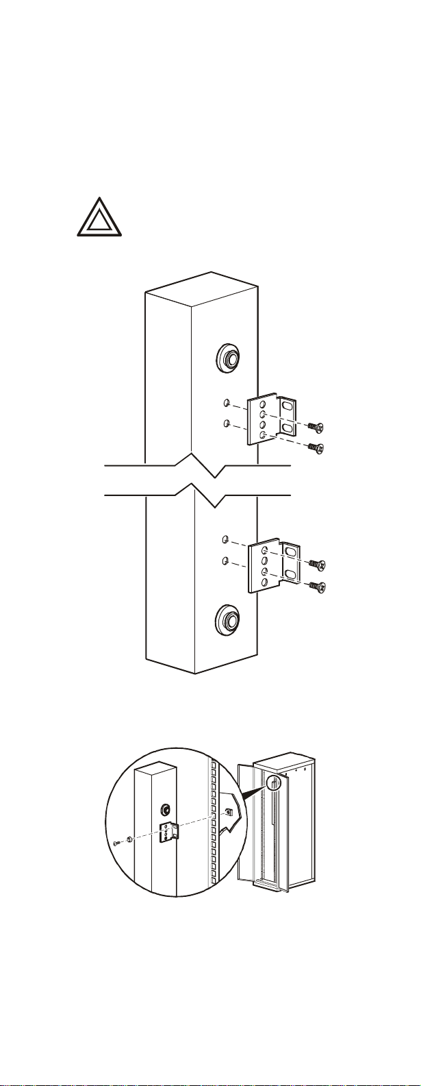
Bracket mounting
Vertical mounting. To mount the PDU
vertically in a NetShelter or any standard EIA-310
rack or enclosure:
1. Attach the vertical-mounting brackets to the
PDU.
Use only the supplied screws.
Caution
pdu0344a
2. Install the PDU on a vertical mounting rail in
your rack or enclosure using the screws and
cage nuts supplied with your enclosure.
pdu0190b
4 Metered Rack Power Distribution Unit
Page 9
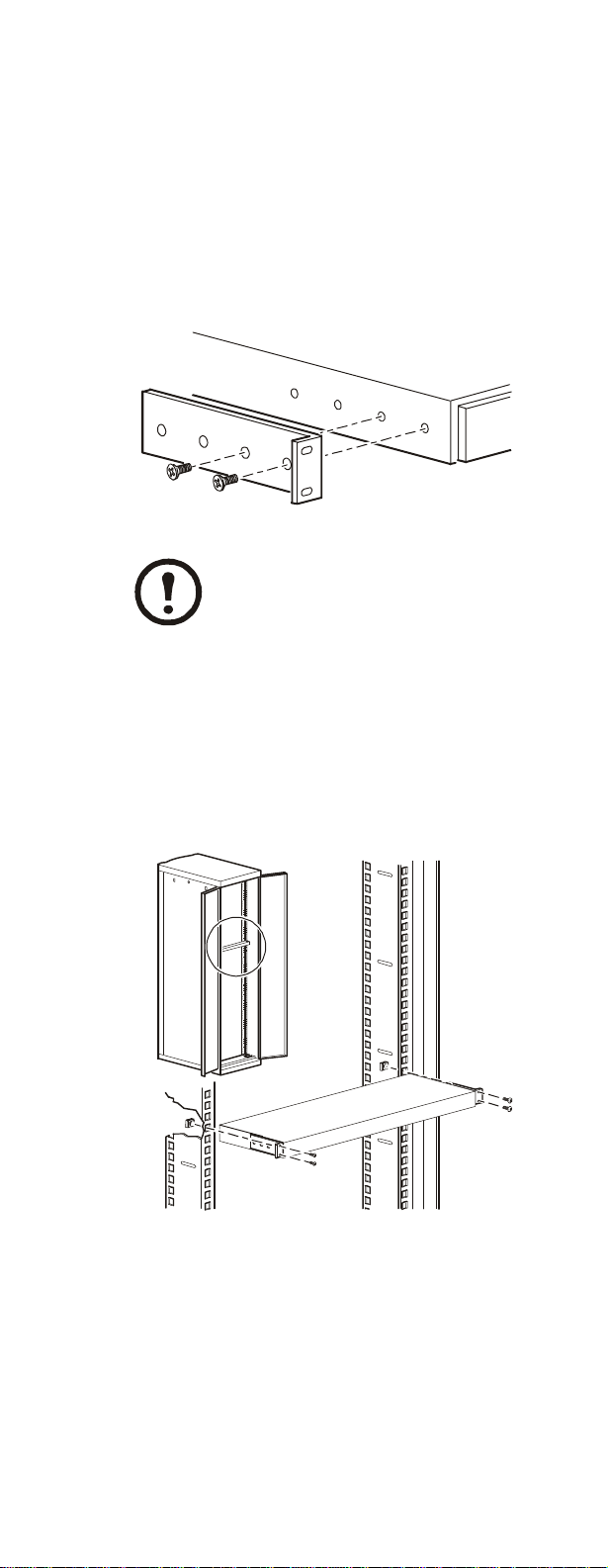
Horizontal mounting. You can mount the PDU in
a 19-inch NetShelter or other EIA-310-D standard
19-inch rack:
1. Choose a mounting position for the PDU with
either the display or the rear facing out of the
enclosure.
2. Attach the mounting brackets to the PDU,
using the flat-head screws (provided).
3. Choose a location for the unit:
The unit occupies one U-space. A
notched hole (or a number, on newer
enclosures) on the enclosure’s vertical
Note
rail indicates the middle of a U-space.
a. Insert cage nuts (provided with the
enclosure) above and below a notched hole
on each vertical mounting rail in your chosen location.
b. Align the mounting holes of the brackets
with the installed cage nuts. Insert and
tighten screws.
pdu0352a
pdu0353a
Metered Rack Power Distribution Unit 5
Page 10

Recessed ho rizontal mounting. You can mount
the PDU in a recessed configuration by attaching
the brackets as shown in the following illustration
of the PDU.
pdu0369a
6 Metered Rack Power Distribution Unit
Page 11

Display Interface Operation
- OK
B1 B2
- Warning
— TOTAL —
- Overload
Amps
Reset
Bank/phase indicator LEDs:
• Indicate the bank/phase corresponding to the current
Press to
select bank.
Press and hold
to invert display.
Amps
Link - Rx/Tx
10/100
Status
Metered Rack PDU
Serial Por t
listed in the digital display.
• Indicate normal (green), warning (yellow), or alarm
(red) condition.
N
OTE: If all indicator LEDs are lit, the Rack PDU is
in use at its maximum capacity.
Control button:
• Press to change the bank/phase of the current
displayed on the digital display.
• Press and hold for five seconds to view the
orientation of the display; hold for an additional five
seconds to change the orientation.
Ethernet port: Connects the PDU to your network,
using a CAT5 network cable.
Status LED: Indicates the status of the Ethernet LAN
connection and the state of the PDU.
• Off–The PDU has no power.
• Solid green–The PDU has valid TCP/IP settings.
• Flashing green–The PDU does not have valid TCP/
IP settings.
• Solid orange–A hardware failure has been detected
in the PDU. Contact Customer Support at a phone
number on the back cover of this manual.
• Flashing orange–The PDU is making BOOTP
requests.
Link LED: Indicates whether there is activity on the
network.
Serial port: Access internal menus by connecting this
port (RJ-11 modular port) to a serial port on your
computer, using the supplied serial cable (part number
940-0144).
Display of the current used by the PDU and attached
devices:
• Shows the aggregate current for the bank/phase
corresponding to the Bank/Phase Indicator LED that
is illuminated.
• Cycles through the banks/phases in 3-second
intervals.
Reset switch: Resets the PDU without affecting the
outlets.
See “Front Panel” in the “Introduction”
of the User’s Guide for more detailed
display information on single-phase
See also
and three-phase
PDUs.
pdu0 291a
Metered Rack Power Distribution Unit 7
Page 12

Quick Configuration
Disregard the procedures in this section if
you have APC InfraStruXure Manager as
Caution
Overview
part of your system. See the InfraStruXure
Manager’s documentation for more
information.
You must configure the following TCP/IP settings
before the
• IP address of the
PDU can operate on a network:
PDU
• Subnet mask
•Default gateway
If a default gateway is unavailable, use
the IP address of a computer that is
located on the same subnet as the
Note
and that is usually running. The
uses the default gateway to test the
network when traffic is very light.
PDU
PDU
Do not use the loopback address
(127.0.0.1) as the default gateway
address. It disables the PDU’s network
Caution
connection and requires you to reset
TCP/IP settings to their defaults using
a local serial login.
See “Watchdog Features” in the
“Introduction” of the User’s Guide for
more information about the watchdog
See also
role of the default gateway.
TCP/IP configuration methods
Use one of the following methods to define the
TCP/IP settings:
• APC Device IP Configuration Wizard (See
“APC Device IP Configuration Wizard” on
page 9)
• BOOTP or DHCP server (See “BOOTP &
DHCP configuration” on page 9.)
• Local computer (See “Local access to the
control console” on page 12.)
• Networked computer (See “Remote access to
the control console” on page 13.)
8 Metered Rack Power Distribution Unit
Page 13

APC Device IP Configuration Wizard
You can use the APC Device IP Configuration
Wizard at a computer running Microsoft
Windows
®
2000, Windows 2003, or Windows XP
®
to configure the basic TCP/IP setting of a Rack
PDU.
Most software firewalls must be
temporarily disabled for the Wizard to
Note
discover unconfigured
PDUs
1. Insert the APC Metered and Switched Rack
Power Distribution Units Utility CD into a
computer on your network.
2. Launch the Wizard, when prompted, or, if
prompted to restart the computer, access the
Wizard from the Start menu after the
computer has restarted.
3. Wait for the Wizard to discover the
unconfigured
PDU, then follow the
on-screen instructions.
If you leave the S tart a Web browser
when fi ni sh ed option enabled, you can
use apc for both the user name and
Note
password to access the Metered Rack
PDU through your browser.
BOOTP & DHCP configuration
The TCP/IP option in the Network menu, under
the Administration tab of the Web interface
identifies how TCP/IP settings will be defined. The
possible settings are Manual, DHCP, BOOTP,
and DHCP & BOOTP (the default setting).
The DHCP & BOOTP setting assumes that a
properly configured DHCP or BOOTP server is
available to provide TCP/IP settings to the
If these servers are unavailable, see
“APC Device IP Configuration
Wizard” on this page, “Local access to
the control console” on page 12, or
“Remote access to the control console”
on page 13 to configure the TCP/IP
settings.
With TCP/IP configuration set to DHCP &
BOOTP, the
PDU attempts to discover a properly
configured server. It first searches for a BOOTP
server, and then a DHCP server. It repeats this
pattern until it discovers a BOOTP or DHCP
server.
For more information, see “BOOTP”
on page 10 or “DHCP” on page 11.
PDU.
Metered Rack Power Distribution Unit 9
Page 14

BOOTP. You can use an RFC951-compliant
BOOTP server to configure the TCP/IP settings for
the
PDU. If the BOOTP server is properly
configured, the
PDU’s default setting (DHCP &
BOOTP) for TCP/IP configuration causes it to
discover the BOOTP server.
If a BOOTP server is unavailable, see
“APC Device IP Configuration
Wizard” on page 9, “Local access to
the control console” on page 12, or
“Remote access to the control console”
on page 13 to configure TCP/IP
settings.
1. Enter the
PDU’s MAC and IP addresses, the
subnet mask and default gateway settings, and
an optional bootup file name in the
BOOTPTAB file of the BOOTP server.
For the MAC address, look on the back
of the PDU or on the Quality
Assurance slip included in the
package.
2. When the
PDU reboots, the BOOTP server
provides it with the TCP/IP settings.
If you specified a bootup file name, the PDU
attempts to transfer that file from the
BOOTP server using TFTP or FTP. The
PDU assumes all settings specified in the
bootup file.
If you did not specify a bootup file name,
the
PDU can be configured remotely by
using Telnet or by using the Web interface:
user name and password are both apc, by
default.
To create a bootup file, see your
BOOTP server documentation.
See also
10 Metered Rack Power Distribution Unit
Page 15

DHCP. You can use a RFC2131/RFC2132-
compliant DHCP server to configure the
TCP/IP settings for the
PDU.
This section summarizes the PDU
communication with a DHCP server.
For more detail about how a DHCP
See also
server is used to configure the network
settings for the
PDU, see “DHCP
Configuration Settings” in the User’s
Guide.
1. The
PDU sends a DHCP request that uses the
following to identify itself:
Vendor Class Identifier (APC by default)
Client Identifier (by default, the PDU’s
MAC address)
User Class Identifier (by default, the
identification of the
PDU’s application
firmware)
2. A properly configured DHCP server responds
with a DHCP offer that includes all of the
settings that the
PDU needs for network
communication. The DHCP offer also includes
the Vendor Specific Information option
(DHCP option 43). By default, the
PDU
ignores DHCP offers that do not encapsulate
the APC cookie in the Vendor Specific
Information option using the following
hexidecimal format:
Option 43 = 01 04 31 41 50 43
where
The first byte (01) is the code
The second byte (04) is the length
The remaining bytes (31 41 50 43) are
the APC cookie
See your DHCP server documentation
to add code to the Vendor Specific
See also
Information option.
You can use a local computer to disable
the APC cookie requirement. To use a
local computer, see “Local access to
the control console” on page 12. To
change the control console’s DHCP
Cookie Is setting, an Advanced option
in the TCP/IP menu, use Telnet or
another remote accessing method. To
access the control console, see
“Remote access to the control console”
on page 13.
Metered Rack Power Distribution Unit 11
Page 16

Local access to the control console
You can use a local computer to connect to the
PDU to access the control console.
1. Select a serial port at the local computer, and
disable any service which uses that port.
2. Use the serial cable (940-0144) to connect the
selected port to the serial port on the front
panel of the PDU.
3. Run a terminal program (such as
HyperTerminal
®
) and configure the selected
port for 9600 bps, 8 data bits, no parity, 1 stop
bit, no flow control, and save the changes.
4. Press
ENTER to display the User Name
prompt.
5. Use apc for the user name and password.
6. See “Control console” on page 14 to finish the
configuration.
12 Metered Rack Power Distribution Unit
Page 17

Remote access to the control console
From any computer on the same subnet as the
PDU,
you can use ARP and Ping to assign an IP address
to the
PDU, and then use Telnet to access that
PDU’s control console and configure the needed
TCP/IP settings.
After the PDU has its IP address
configured, you can use Telnet,
without first using ARP and Ping, to
Note
access that
1. Use ARP to define an IP address for the
and use the
PDU.
PDU,
PDU’s MAC address in the ARP
command. For example, to define an IP
address of 156.205.14.141 for the
PDU that has
a MAC address of 00 c0 b7 63 9f 67, use one
of the following commands:
Windows command format:
arp -s 156.205.14.141 00-c0-b7-63-9f-67
LINUX command format:
arp -s 156.205.14.14 1 00:c0:b 7:63:9 f:67
The MAC address is on the back of the
PDU and on the Quality Assurance slip
Note
included in the package.
2. Use Ping with a size of 113 bytes to assign the
IP address defined by the ARP command. For
example:
Windows command format:
ping 156.205.14.141 -l 113
LINUX command format:
ping 156.205.14.141 -s 113
3. Use Telnet to access the PDU at its newly
assigned IP address. For example:
telnet 156.205.14.141
4. Use apc for both user name and password.
5. See “Control console” on page 14 to finish the
configuration.
Metered Rack Power Distribution Unit 13
Page 18

Control console
After you log on at the control console, as
described in “Local access to the control console”
on page 12 or “Remote access to the control
console” on page 13:
1. Choose Network from the Control Console
menu.
2. Choose TCP/IP
from the Network menu.
3. If you are not using a BOOTP or DHCP server
to configure the TCP/IP settings, select the
Boot Mode menu. Select Manual boot mode,
and then press
menu. Set the System
ESC to return to the TCP/IP
IP, Subnet Mask, and
Default Gateway address values.(Changes
will take effect when you log off.)
4. Press
CTRL+C to exit to the Control Console
menu.
5. Log off (option 4 in the Control Console
menu).
If you disconnected a cable during the
procedure described in “Local access
to the control console” on page 12,
Note
reconnect that cable and restart the
associated service.
14 Metered Rack Power Distribution Unit
Page 19

Access a Configured PDU
Overview
After the
PDU is running on your network, you can
use the interfaces summarized here to access the
unit.
For more information on the interfaces,
see the User’s Guide.
See also
Web interface
Use Microsoft
®
Internet Explorer (IE) 5.5 or
higher (on Windows operating systems only),
Firefox, version 1.x, by Mozilla Corporation (on
all operating systems), or Netscape
®
7.x or higher
(on all operating systems) to access the PDU
through its Web interface. Other commonly
available browsers also may work but have not
been fully tested by APC.
To use the Web browser to configure
PDU options
or to view the event log, you can use either of the
following:
• The HTTP protocol (enabled by default),
which provides authentication by user name
and password but no encryption.
• The more secure HTTPS protocol, which
provides extra security through Secure Socket
Layer (SSL) and encrypts user names,
passwords, and data being transmitted. It also
provides authentication of
PDUs by means of
digital certificates.
To access the Web interface and configure the
security of your device on the network:
1. Address the
PDU by its IP address or DNS
name (if configured).
2. Enter the user name and password (by default,
apc and apc for an Administrator, or device
and apc for a Device Manager).
3. Select and configure the type of security you
want. (This option is available only for
Administrators.)
See the Security Handb ook: Network-
Enable d Devices, available on the
Metered/Switched Rack PDU Utility
See also
CD or from the APC Web site,
www.apc.com, for more information
on selecting and configuring network
security.
Metered Rack Power Distribution Unit 15
Page 20

Telnet and SSH
You can access the control console through Telnet
or Secure SHell (SSH), depending on which is
enabled. (On the Administration tab, select
Network on the top menu bar and select Access
under the Console heading on the left navigation
menu to enable these access methods.) By default,
Telnet is enabled. Enabling SSH automatically
disables Telnet.
T elnet for basic access. Telnet provides the
basic security of authentication by user name and
password, but not the high-security benefits of
encryption. To use Telnet to access a
PDU control
console from any computer on the same subnet:
1. At a command prompt, use the following
command line, and press
ENTER:
telnet address
As address, use the
PDU’s IP address or
DNS name (if configured).
2. Enter the user name and password (by default,
apc and apc for an Administrator, or device
and apc for a Device Manager).
SSH for high-s ecurity access. If you use the
high security of SSL for the Web interface, use
Secure SHell (SSH) for access to the control
console. SSH encrypts user names, passwords, and
transmitted data.
The interface, user accounts, and user access rights
are the same whether you access the control
console through SSH or Telnet, but to use SSH,
you must first configure SSH and have an SSH
client program installed on your computer.
See the User’s Guide for more
information on configuring and using
See also
SSH.
SNMP
After you add the PowerNet MIB to a standard
SNMP MIB browser, you can use that browser for
SNMP access to the
PDU. The default read
community name is public; the default read/write
community name is private.
To use InfraStruXure Manager to manage a
PDU
on the public network of an InfraStruXure system,
you must have SNMP enabled in the
PDU
interface.
To enable or disable SNMP access, you must be an
Administrator. Select the Administrator tab,
select the Network menu on the top menu bar, and
use the access option under SNMP on the left
navigation menu.
16 Metered Rack Power Distribution Unit
Page 21

FTP and SCP
You can use FTP (enabled by default) or Secure
CoPy (SCP) to transfer downloaded firmware to
the
PDU, or to access a copy of the PDU’s even t or
data logs.
To use InfraStruXure Manager to manage a
you must have FTP Serv er enabled in the
interface.
To enable or disable FTP Server access, you must
be an Administrator. Select the Administration
tab, select the Network menu on the top menu bar,
and use the FTP Server option on the left
navigation menu.
In the Metered Rack PDU User’s
Guide, see the following sections:
See also
• To transfer firmware, see “File
Transfers.”
• To retrieve a copy of the event or
data log, see “How to use FTP or
SCP to retrieve log files.”
Managing the security of your system
For detailed information on
enchancing the security of your system
after installation and initial
See also
configuration, see the Security
Handbook, available on the APC
Metered / Switched Rack PDU Utility
CD and on the APC Web site,
www.apc.com.
PDU,
PDU
Metered Rack Power Distribution Unit 17
Page 22

How to Recover From a Lost Password
You can use a local computer, a computer that
connects to the PDU or other device through the
serial port, to access the control console.
1. Select a serial port at the local computer, and
disable any service that uses that port.
2. Connect the serial cable (940-0144) to the
selected port on the computer and to the
configuration port at the PDU.
3. Run a terminal program (such as
HyperTerminal) and configure the selected
port as follows:
9600 bps
8 data bits
no parity
1 stop bit
no flow control
4. Press
5. Press the Reset button. The Status LED will
6. Press
7. From the Control Console menu, select
8. Select Administrator, and change the User
9. Press
ENTER, repeatedly if necessary, to
display the User Name prompt. If you are
unable to display the User Name prompt,
verify the following:
The serial port is not in use by another
application.
The terminal settings are correct as
specified in step 3.
The correct cable is being used as specified
in step 2.
flash alternately orange and green. Press the
Reset button a second time immediately while
the LED is flashing to reset the user name and
password to their defaults temporarily.
ENTER as many times as necessary to
redisplay the User Name prompt, then use the
default, apc, for the user name and passw ord.
(If you take longer than 30 seconds to log on
after the User Name prompt is redisplayed,
you must repeat step 5 and log on again.)
System, then User Manager.
Name and Password settings, both of which
are now defined as apc.
CTRL+C, log off, reconnect any serial
cable you disconnected, and restart any service
you disabled.
18 Metered Rack Power Distribution Unit
Page 23

How to Update Firmware
To obtain firmware for your PDU, download the
latest firmware revision from
www.apc.com/tools/download on the APC Web
site.
For a complete description on how to
transfer a downloaded firmware
See also
Caution
Note
upgrade to your
Transfers” in the Metered Rack PDU
User’s Guide on the provided APC
Metered and Switched Rack Power
Distribution Units Utility CD and also
available from the APC web site.
Do not interrupt the transfer.The PDU
will reboot when the transfer is
complete.
Upgrading the firmware will not
interfere with the operation of the
outlets.
PDU, see “File
Metered Rack Power Distribution Unit 19
Page 24

Warranty and Service
Limited warranty
APC warrants the Metered Rack Power
Distribution Unit to be free from defects in
materials and workmanship for a period of two
years from the date of purchase. Its obligation
under this warranty is limited to repairing or
replacing, at its own sole option, any such
defective products. This warranty does not apply to
equipment that has been damaged by accident,
negligence, or misapplication or has been altered
or modified in any way. This warranty applies only
to the original purchaser.
Warranty l imitations
Except as provided herein, APC makes no
warranties, expressed or implied, including
warranties of merchantability and fitness for a
particular purpose. Some jurisdictions do not
permit limitation or exclusion of implied
warranties; therefore, the aforesaid limitation(s) or
exclusion(s) may not apply to the purchaser.
Except as provided above, in no event will APC
be liable for direct, indirect, special, incidental,
or consequential damages arising out of the use
of this product, even if advised of the possibility
of such damage.
Specifically, APC is not liable for any costs, such
as lost profits or revenue, loss of equipment, loss
of use of equipment, loss of software, loss of data,
costs of substitutes, claims by third parties, or
otherwise. This warranty gives you specific legal
rights and you may also have other rights, which
vary according to jurisdiction.
Obtaining service
To obtain support for problems with your Metered
Rack Power Distribution Unit:
0
1. Note the serial number. The serial number is
located on the bottom of the PDU.
2. Contact Customer Support at a phone number
on the back cover of this document. A
technician will try to help you solve the
problem by phone.
3. If you must return the product, the technician
will give you a return material authorization
(RMA) number. If the warranty expired, you
will be charged for repair or replacement.
20 Metered Rack Power Distribution Unit
Page 25

4. Pack the unit carefully. The warranty does not
cover damage sustained in transit. Enclose a
letter with your name, address, RMA number
and daytime phone number; a copy of the sales
receipt; and a check as payment, if applicable.
5. Mark the RMA number clearly on the outside
of the shipping carton.
6. Ship by insured, prepaid carrier to the address
provided by the Customer Support technician.
Metered Rack Power Distribution Unit 21
Page 26

Life-Support Policy
General policy
American Power Conversion (APC) does not
recommend the use of any of its products in the
following situations:
• In life-support applications where failure or
malfunction of the APC product can be
reasonably expected to cause failure of the
life-support device or to affect significantly its
safety or effectiveness.
• In direct patient care.
APC will not knowingly sell its products for use in
such applications unless it receives in writing
assurances satisfactory to APC that (a) the risks of
injury or damage have been minimized, (b) the
customer assumes all such risks, and (c) the
liability of APC is adequately protected under the
circumstances.
Examples of life-support devices
The term life-support dev ice includes but is not
limited to neonatal oxygen analyzers, nerve
stimulators (whether used for anesthesia, pain
relief, or other purposes), autotransfusion devices,
blood pumps, defibrillators, arrhythmia detectors
and alarms, pacemakers, hemodialysis systems,
peritoneal dialysis systems, neonatal ventilator
incubators, ventilators (for adults and infants),
anesthesia ventilators, infusion pumps, and any
other devices designated as “critical” by the U.S.
FDA.
Hospital-grade wiring devices and leakage current
protection may be ordered as options on many
APC UPS systems. APC does not claim that units
with these modifications are certified or listed as
hospital-grade by
Therefore these units do not meet the requirements
for use in direct patient care.
APC or any other organization.
22 Metered Rack Power Distribution Unit
Page 27

Page 28

APC Worldwide Customer
Support
Customer support for this or any other APC product is available at
no charge in any of the following ways:
• Visit the APC Web site to access documents in the APC
Knowledge Base and to submit customer support requests.
– www.apc.com (Corporate Headquarters)
Connect to localized APC Web sites for specific
countries, each of which provides customer support
information.
– www.apc.com/support/
Global support searching APC Knowledge Base and
using e-support.
• Contact an APC Customer Support center by telephone or
e-mail.
– Regional centers:
Direct InfraStruXure
Customer Support Line
APC headquarters U.S.,
Canada
Latin America (1)(401)789-5735
Europe, Middle East,
Africa
Japan (0) 35434-2021
Australia, New Zealand,
South Pacific area
– Local, country-specific centers: go to www.apc.com/
support/contact for contact information.
Contact the
you purchased your
obtain local customer support.
Entire contents copyright 2006 American Power Conversion
Corporation. All rights reserved. Reproduction in whole or in
Power Conversion Corporation. All other trademarks, product
names, and corporate names are the property of their respective
APC representative or other distributor from whom
APC product for information on how to
part without permission is prohibited. APC, the APC logo,
NetShelter, and InfraStruXure are trademarks of American
owners and are used for informational purposes only.
(1)(877)537-0607
(toll free)
(1)(800)800-4272
(toll free)
(USA)
(353)(91)702000
(Ireland)
(61) (2) 9955 9366
(Australia)
990-1903B-001
05/2006
*990-1903B-001*
 Loading...