

Page 1
Rack Power Distribution Unit — AP7610
Product Description and Inventory
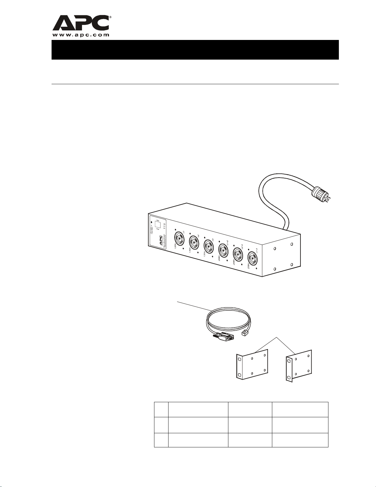
Description
The AP7610 Rack PDU mounts horizontally in any standard 19-inch
EIA-310-compliant rack or enclosure. This Rack PDU is metered —
equipped with a sensor t hat measur es the cu rrent be ing used by the Rack
PDU and any devices connected to it. The value shown on the display
interface is the aggregate current of an individual phase. This value will
generate an alarm if it is outside the threshold values that you define.
This Rack PDU has three L5-20 outlets, three L6-20 outlets, and a
L21-20 plug.
Inventory
Description Part Number Quantity
Serial cable
Rack-mount brackets 870-1466 2
940-0144 1
Page 2

Product Description and Inventory
AP7610-compatible Rack
PDUs
The AP7610 Metered Rack PDU requires connection to an additional
Rack PDU. T he following APC Rack PDUs are compatible with the
AP7610:
Compatible APC 120V PDUs
PDU Plug Outlets Manageable
AP9563 L5-20 Ten NEMA 5-20 No
AP9551 L5-20 Fourteen NEMA 5-15 No
AP9228 L5-20 Sixteen NEMA 5-15 Yes
Compatible APC 208V PDUs
PDU Plug Outlets Manageable
AP9558 L6-20 Twelve IEC 320-C13 No
AP9559
AP9554
AP9229
†
Using thes e R ac k PDU s w ith AP 7610 requ ires an a dditional power cord (AP98 71 ) .
†
IEC 320 C20 Ten IEC 320-C13;
Two IEC 320-C19
†
IEC 320 C20 Fourteen IEC 320-C13 No
†
IEC 320 C20 Eight IEC 320-C13 Yes
No
Power cord available for
purchase
The following power cord can be purchased from APC:
APC SKU Description Cord Ends
IEC 320 C19
AP9871
to
NEMA L6-20
2 Rack Power Distribution Unit — AP7610
Page 3

Safety and Grounding
C
Read the following information before install ing or o per at ing your APC
AP7610 Rack PDU:
• The Rack PDU is intended only for use with four-wire grounded
connections on APC Uninterruptible Power Supplies (UPS). Do
not plug the Rack PDU into a wall outlet or other device.
• This Rack PDU is intended to be installed and operated only with
the provided mounting hardware.
• This Rack PDU is intended for indoor use only.
• Do not install this Rac k PDU where excessive moisture or heat is
present.
• Do not use extension cords or adapters with this Rack PDU.
• Check that the power cord, plug, and socket are in good condition.
• Disconnect the Rack PDU fro m the power o utlet before you inst all
or connect equipment to reduce the ri sk of elect ric shock whe n you
cannot verify grounding. Reconnect the Rack PDU to the power
outlet only after you make all connections.
• Install the Rack PDU so that the power plug may be disconnected
for service. The soc ket -o utlet shall be installed near the equipment
and shall be readily accessible.
• Install the Rack PDU so that there is not an uneven mechanical
load.
• Follow the nameplate ratings when connecting equipment to the
supply circuit. Do no t overload the circu it s. An ove rload condition
could put your over-current protection at risk or cause problems
with your supply wiring.
• This Rack PDU contains a non-replaceable lithium coin cell
battery. Do not attempt to replace the battery.
Risk of electrical shock. Use only the supplied hardware to
attach the mounting brackets.
aution
Rack Power Distribution Unit — AP7610 3
Page 4
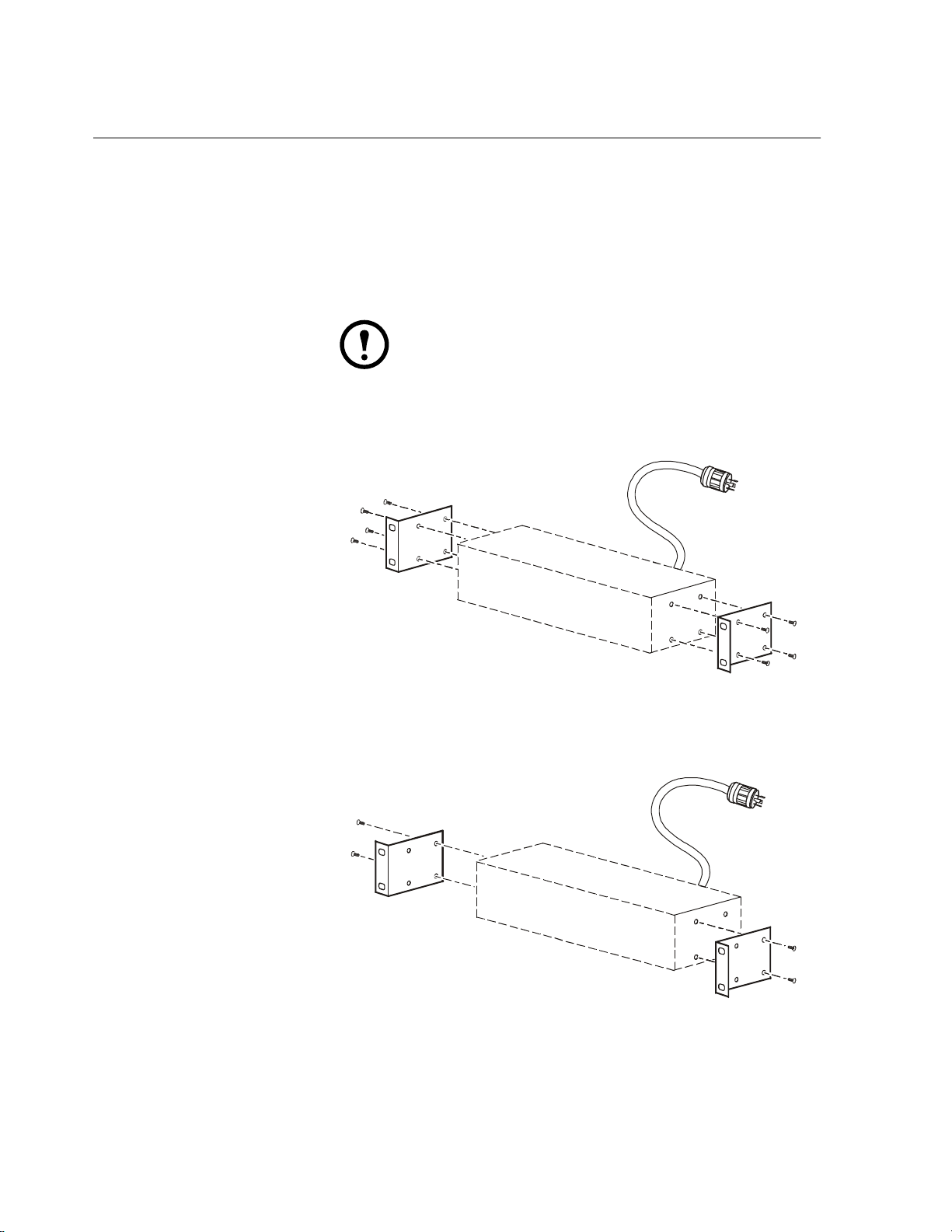
How to Install the PDU
Overview
Install the AP7610 Rack PDU in the rear, top two U-spaces of a rack or
enclosure for overhead wiring, or in the rear, bottom two U-spaces for
under-floor wiring. To install the Rack PDU in a NetShelter
Enclosure:
1. Attach a bracket t o each side of the Ra ck PDU, using the pan- head
screws.
Some enclosures may require you to recess the Rack
PDU so that the back doors of the enclosure will close
Note
For placement flush-to-rack: use four pan-head screws (provided)
for each bracket.
when other devices are plugged in.
®
Stan dard
For a recessed placement: use two pan-head screws (provided)
through the last two holes of the mounting brackets and into the
first two holes on the Rack PDU.
4 Rack Power Distribution Unit — AP7610
Page 5
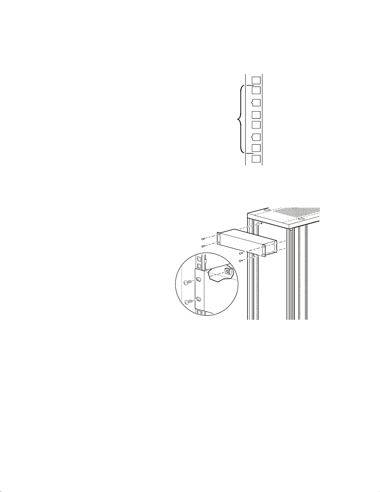
How to Install the PDU
1. Insert caged nuts (provided with the enclosure) on the vertical
mounting rails above a notched hole at the start of the top two
U-spaces in your enclosure and below the notched hole at the
lower end of the two U-spaces.
2U
2. Align the mounting holes on the brackets with the caged nuts you
installed in step 1, and insert four mounting screws (pr ovi ded wi th
the enclosure) to secure the brackets to the enclosure.
Rack Power Distribution Unit — AP7610 5
Page 6

Operation
Display interface
Control button:
• Press to change the phase of the current displayed on the digital
display.
• Press and hold for five seconds to view the orientation; hold for an
additional five seconds to change the orientation.
Display of the current used by the Rack PDU and attached devices:
• Shows the aggregate current for the phase corresponding to the Phase
Indicator LED that is illuminated.
• Cycles through all three phases in 3-second intervals.
Phase indicator LEDs:
• Indicates the phase corresponding to the current listed in the digital
display.
• Indicates normal (green), warning (yellow), or alarm (red) condition.
6 Rack Power Distribution Unit — AP7610
Page 7

Rear of AP7610
Operation
Alarm conditions
Serial port: Access internal menus by connecting this
port (RJ-11 modular port) to a serial port on your
computer, using the supplied serial cable (part number
940-0144).
Status LED: Indicates the status of the network
connection and the state of the Rack PDU.
Ethernet port: Connects the Rack PDU to the
InfraStruXure
Link LED: Indicates whether there is activity on the
network.
Configure warning and alarm limits through the internal menus, using a
serial port connection.
The Rack PDU shows warning and alarm conditions as follows:
™
network, using a CAT-5 network cable.
Phase Indicator LED Displays yellow for a warning and red for an
alarm.
Digital display If one phase is at or above the warning or
alarm limit, the display shows the current for
that phase.
If more than one phase is at or above the
warning or alarm limit, the display cycles
among those phases, displaying their current.
Control Button Pressing this button causes the digital display
to display the current for the next phase for 30
seconds. Then it returns to the display of the
current for any phases that are at or above the
warning or alarm limits.
Do not exceed the maximum voltage and current
ratings listed on the rear panel of the Rack PDU.
Warning
Rack Power Distribution Unit — AP7610 7
Page 8
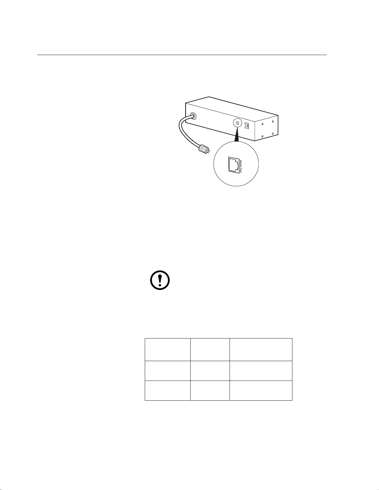
Rack PDU Configuration
How to configure
through a serial port
connection
1. Connect an availa ble se rial port on your c omputer to th e seri al po rt
on the Rack PDU (shown below), using the suppli ed confi gurat ion
cable (940-0144).
2. Run a terminal emulation program such as Windows
®
HyperTerminal.
3. Configure the following settings for the serial port:
– 19,200 bps
–no parity
– 8 data bits
–1 stop bit
– no flow control
Some terminal emulation programs require that a
device be disconnected and then reconnected for
Note
the new serial port settings to take effect.
4. Press any key on the computer to display the Rack PDU login
screen, which contains the username and password prompts.
5. Log on by using the user name and password for the appropriate
access level:
Access Level
Administrator Press
User Press
l
Default
User Name
ENTER.
ENTER.
Default Password
Type apc (in
lowercase).
ESC.
Press
8 Rack Power Distribution Unit — AP7610
Page 9

Rack PDU Configurati on
Using the menus
To view a menu, type the associated number and press ENTER.
Users can view all data, but only administrators can configure
parameters.
The main menu has the following options:
Option
Number
1 Status
2 Rack PDU
3 Device Data Users can display the
4 Factory Data User and Administrator
5 Logout User and Administrator
6 System
Option Access
User and Administrator
Information
Users can display the
Configuration
Management
parameters. Administrators
can configure them.
parameters. Administrators
can configure them.
Available only when you
are logged in as
Administrator.
Status Information
option
Stat us Informati on, main menu opt ion 1, displ ays the out put curren t, in
amps, for each phase from the Rack PDU and reports if the lo ad is at or
above the configured limits for output current.
Rack Power Distribution Unit — AP7610 9
Page 10

Rack PDU Configuration
Rack PDU Configuration
option
Rack PDU Configuration, main menu opti on 2 , provi des th e fo llowin g
options:
Option
Number
1 Warning and Alarm
Threshold Data for output
current.
2 Audio/Visual Indicator
Settings to enable or disable the
audible alarm and digital
display and to set the
orientation of the display.
Option Access
Users can display
the parameters.
Administrators can
configure them.
Settings are displayed for each phase.
• To change a warning and alarm threshold, type the number of the
setting, press
ENTER, type the new value, and press ENTER again.
• To change an audio/visual indicator setting:
a. Type
1, and press ENTER to move the arrow cursor to the next
setting.
Device Data option
b. Type
2, and press ENTER to change the selected setting.
c. Type the number listed for the setting you want, and press
ENTER.
Device Data, main menu option 3, has the following settings:
D
Setting Description Access
Product
Name
Product
Location
Contact
Information
Log
Timeout
(mins)
Admin
Password
A unique name that you
assign to the device.
For example, the enclosure
in which the Rack PDU is
installed.
For example, a name or
phone number of a person to
contact.
The number of minutes a
user can be inactive before
being logged off.
The password of the
Administrator account
(displayed as asterisks to
users).
Users can
display the
parameters.
Administrators
can configure
them.
10 Rack Power Dis t r ibution Unit — AP7610
Page 11

To change as setting:
Rack PDU Configurati on
Factory Data option
Logout option
System Management
option
1. Type
1, and press ENTER to move the arrow cursor to the next
setting.
2. Type
3. Type the new value, and press
2, and press ENTER to change the selected setting.
ENTER.
Factory Data, main menu option 4, displays the following information
about the Rack PDU:
• Model number
• Serial number
• Hardware revision
• Date of manufacture
• Firmware revision
• Date on which the firmware was installed
You cannot change any of these items.
Logout, main menu option 5, logs you off from the interface.
System Management, main menu option 6, is accessible onl y when you
are logged on as Administrator.
T ype the number of any o ne of the fo llowing opt ions, a nd press
select it.
Option
Number
1 Restart
2 Restore
3 Firmware
Option Description
Restarts the Rack PDU
RMPDU
Default
Parameters
and Restart
Download
while maintaining the
present settings.
Resets all parameters to their
default settings, and restarts
the Rack PDU.
Prepares to download
firmware. See“How to
Download Firmware to a
Rack PDU” on page 12.
ENTER to
Rack Power Distribution Unit — AP7610 11
Page 12

How to Download Firmware to a Rack PDU
During firmware downloads, power will not
be interrupted to the Rack PDU outlets.
Note
1. Go to www.apc.com/tools/download/ to see if there is a more
recent firmware version for your type of Rack PDU.
2. Access the Rack PDU internal menus through a serial port
connection.
Follow the instructions in “How to configure through
a serial port connection” on page 8.
3. Log on to the Rack PDU as an Administrator.
4. Type
5. Type
6 (for System Management) on the Main menu and press
E
NTER
.
3 (for Firmware Download) on the System Management
menu, and press
E
NTER
.
6. From the Firmware Download menu:
a. Type 1 and press
displays
C repeatedly and the display interface displays dL.
E
NTER
to initiate a download. The menu
b. Select the Transfer pull-down menu from the menu bar.
c. Select Send File from the Transfer pull-down menu.
d. Browse for and select the firmware file you copied to your
computer.
e. Set the protocol to Xmodem and press the Send button.
When the firmware download is complete, the display interface
refreshes and displays the current in amps.
12 Rack Power Dis t r ibution Unit — AP7610
Page 13

Specifications
AP7610
Electrical
Input connector NEMA L21-20 plug
Output connectors Three NEMA L5-20 outlet; Three NEMA L6-20 out l et
Nominal input voltage 208 (3PH)
Acceptable input voltage 100–125/200–250 VAC
Maximum Input Current
(per phase)
Load Capacity 7200
Physical
Size (H x W x D)
Weight 7.85 lb (3.57 kg)
Shipping dimensions
(H x W x D)
Shipping weight 10.5 lb (4.77 kg)
Environmental
Elevation (above MSL):
Operating:
Storage:
Temperature:
Operating:
Storage:
16 A
3.5 × 17.6 × 6 in
(8.89 x 44.7 x 15.24 cm)
7.75×21×9.25 in
(19.68 x 53.34 x 23.5 cm)
0 to 10,000 ft (0 to 3000 m)
0 to 50,000 ft (0 to 15 000 m)
23 to 133° F (–5 to 45° C)
–13 to 149° F (–25 to 65° C)
Humidity:
Operating:
Storage:
Compliance
Approvals cUL Listed, FCC Part 15 Class A, UL Listed, VCCI
Rack Power Distribution Unit — AP7610 13
5 – 95%
5 – 95% non-condensing
Page 14

Page 15

Radio Frequency Interference
Changes or modifications to this unit not
expressly approved by the party
responsible for complia nce could void the
Warning
This equipment has been te sted and found to co mply with the limit s for a
Class A digital device, pursuant to part 15 of the FCC Rules. These
limits are designed to provide reasonable protection against harmful
interference when the equipment is operated in a commercial
environment. This equipment generates, uses, and can radiate radio
frequency energy and, if not installed and used in accordance with this
user manual, may cause harmful interference to radio communications.
Operation of this equipment in a residential area is likely to cause
harmful interference. The user will bear sole responsibility for
correcting such interference.
This Class A digital apparatus complies with Canadian ICES-003.
user’s authority to operate this
equipment.
Cet appareil numérique de la classe A est conforme à la norme NMB-
a
003 du Canada.
この装置は規定に準拠しています。
この装置を住宅地域またはその周
囲で使用する場合、 ラジオやテレビヘの
電波障害を及ぼすことがあリます。 VCCI-A
Page 16

APC Worldwide Customer Support
Customer su pport for this or any other APC product is available at no charge in any of the following ways:
• Visit the
Knowledge Base, and to submit customer support requests.
– www.apc.com (Corporate Headquarters)
– www.apc.com/support/
• Contact an
– Regional centers:
APC Web site to find answers to frequen tly asked questio ns (FAQs), to access documents in the APC
Connect to localized
information.
Global support with
APC Web sites for specific countries, each of which provides customer support
FAQs, knowledge base, and e-support.
APC Customer Support center by telephone or e-mail.
APC headquarters U.S., Canada (1)(800)800-4272 (toll free)
Latin America (1)(401)789-5735 (USA)
Europe, Middle East, Africa (353)(91)702055 (Ireland)
Japan (0) 35434-2021
– Local, country-specific centers: go to www.apc.com/support/contact for contact information.
Contact the
how to obtain local customer support.
APC representative or ot her d istri butor from w hom you p urchased your APC p roduct for informat ion on
Entire contents copyright © 2003 American Power Conversion. All rights reserved.
Reproduction in whole or in part without permission is prohibited. APC, the APC logo,
InfraStruXure, and NetShelter are trademarks of American Power Conversion Corporation and
may be registered in some jurisdictions. All other trademarks, product names, and corporate
names are the property of their respective own ers and are used for informational purposes only.
990-1474 08/2003
*990-1474*
 Loading...