

Page 1

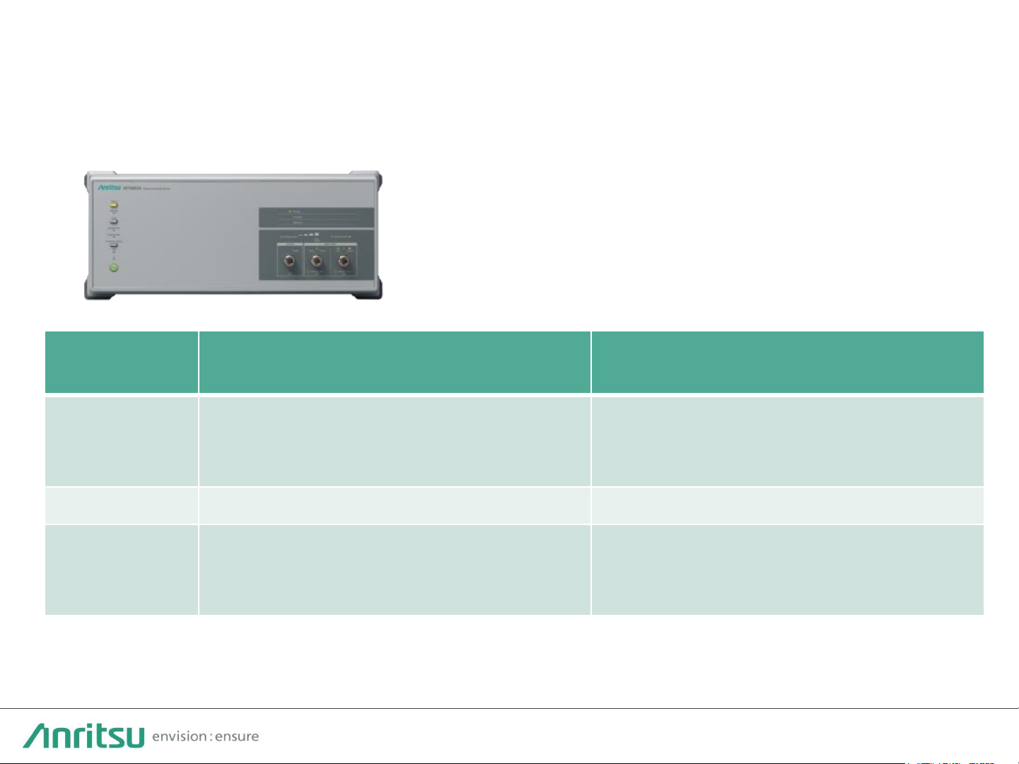
Wireless Connectivity Test Set
MT8862A
Product Introduction
Page 2
2
Contents
• Market Trend & Solutions
• MT8862A Product Introduction
• MT8862A Applications
Page 3

3
M a r k e t Tr e n d & S o l u t i o n s
Page 4
4
0
5
10
15
20
Connected devices
(billions)
Wide-area IoT (30%)
Short-range IoT (20%)
PC/laptop/tablet (0%)
Mobile phones (3%)
Fixed phones (0%)
Rise of Non-cellular IoT Devices and Diversifying Wireless
Standards
Increase in non-cellular IoT devices
The number of Short-range IoT devices is
expected to increase in future and will
exceed the number of mobile phones. It is
assumed that IoT devices will be used for
IoT that will expand in the future.
Source: ERICSSON MOBILITY REPORT JUNE 2017
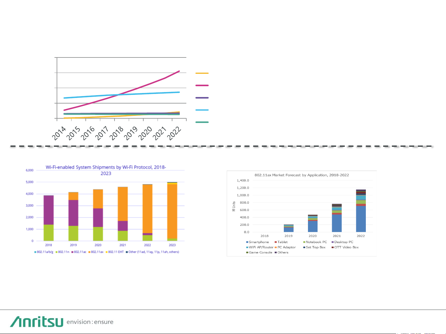
Source : Wi-Fi chipset shipment forecast by IDC towards 2023 Source : 2018 Wireless Connectivity Market Analysis
OTA testing and IEEE 802.11ax spread rapidly
11ax (Wi-Fi 6) is growing rapidly from 2019, it will be the main standard on WLAN specification behalf
on 11ac. Also The demand of OTA test is expected to be increasing for the quality assurance with a
focus on Smartphone market.
Page 5
5
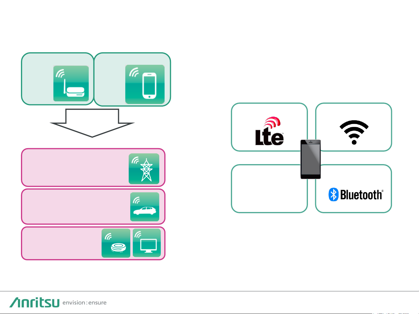
Expanding WLAN applications
Increasing device complexity
WLAN applications are expanding, and usage
environments and quality requirements are changing.
On this background OTA test with network mode is
paid a lot of attention
Devices are using more wireless technologies and
antennas year-by-year, increasing device complexity.
Therefore, shipping products need evaluation more
than ever.
LTE (MIMO) WLAN (MIMO)
BluetoothGNSS
NFC
…Others
Expanding WLAN Applications & Increasing Device
Complexity
Access Point
Router
PC
Smartphone
IoT
Consumer Electronics
(Smart Home)
Automotive
(In-Vehicle Infotainment)
Industry
(Industrial IoT)
Applications
Page 6
6
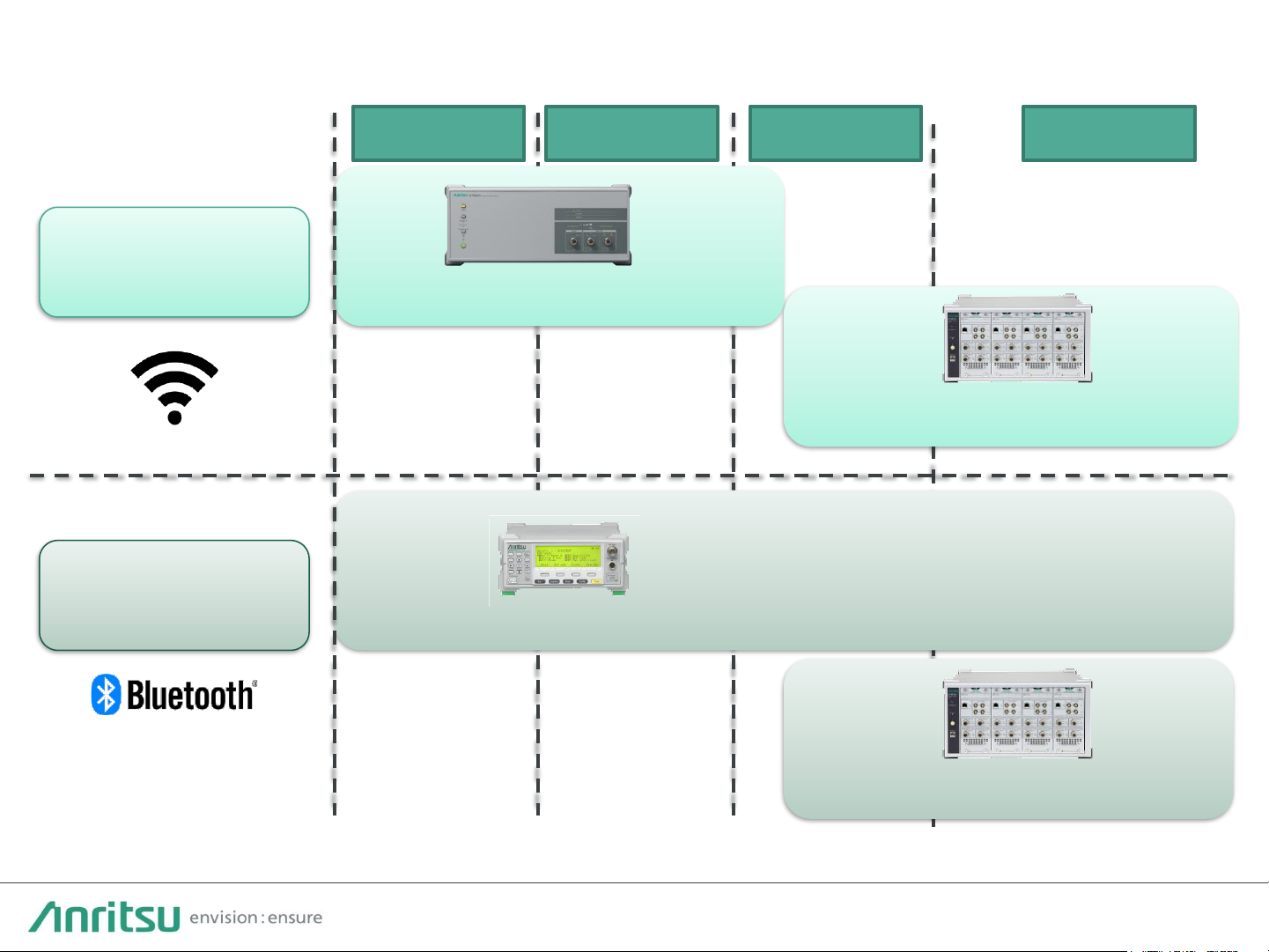
WLAN
Devices
Bluetooth
Devices
Wireless Connectivity Test Set
MT8862A
Universal Wireless Test Set
MT8870A
Universal Wireless Test Set
MT8870A
Bluetooth Test Set
MT8852B
Anritsu has solutions for every stage.
Product
Development
Design
Verification
Prototyping
Mass-
Production
Solutions from Development to Production
Page 7
7
Network Mode
Direct Mode
Advantage
Easy test environment with no DUT
control because measured using
standard connection
Fast measurement because DUT
controlled
directly from external PC
and optimized for mass production
Disadvantage
Time to establish connection
Requires DUT control
Use
Product development
Design
validation
End
-product verification
Prototyping
Product development
Choices matching measurement use because MT8862A has two
measurement mode.
Changing mode Tailored to Use
Wireless Connectivity Test Set
MT8862A
Page 8

8
M T 8 8 6 2 A P r o d u c t I n t r o d u c t i o n
Page 9
9
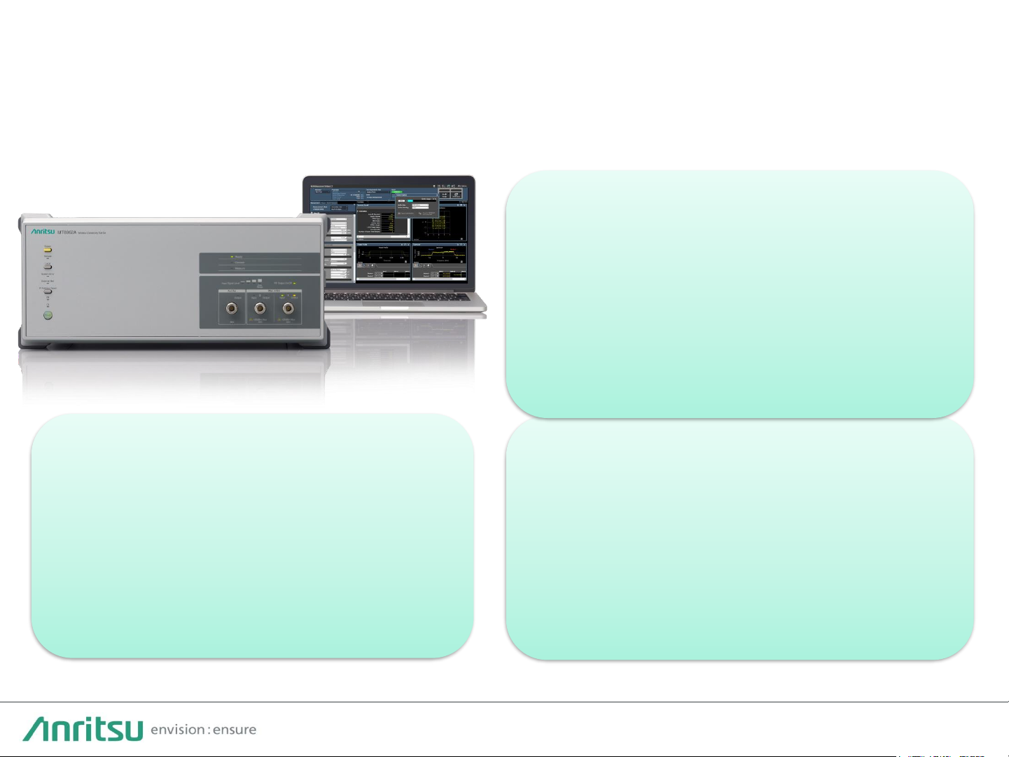
The Wireless Connectivity Test Set MT8862A supports an RF performance
measurement environment under realistic operation conditions (Network Mode).
Wireless Connectivity Test Set
MT8862A
Wide Connectivity Support
Connections are supported in the
IEEE802.11a/b/g/n/ac/ax*12x2MIMO AP
and STA modes. Additionally,
supporting securities, WEP, WPAPersonal and WPA2-Personal, makes
measuring various devices connect in
the Network Mode.
Built-in IP Data Ports
Ethernet ports for IP data are built-in and
IP continuity tests, such as ping between
the external PC client and DUT can be
performed under the same fixedparameter conditions as at measurement.
Tx measurements are also supported
during IP data communication*2.
Intuitive GUI
Setup and measurement use a browser
GUI with access to Web servers from the
PC controller using a Web browser.
Control software installation and firmware
matching are unnecessary, and there is no
dependence on the PC controller OS.
Quality Assurance of Diverse and Complex Devices
*1: 11ax supports SISO and HESU(Single user) and HETB(Multi user for STA).
*2: 11as doesn’t support IP data communication.
Page 10
10
Advantages of RF Measurement in Network Mode
The MT8862A Network Mode supports configuration of an RF measurement
environment without test firmware, chipset control, and hardware modification.
No Test Firmware
Firmware used by commercial products
can be tested and RF measurements can
be made without needing test firmware.
RF control faults which can’t be found
with test firmware can be analyzed.
No Hardware Modification
Since no interface is required for chipset
control, RF tests can be run without
modifying devices. This is ideal for RF
measurements of devices without
interfaces due to needs for
miniaturization, enhanced durability,
and cost control.
No Chipset Control
Chipset control required by test
firmware is unnecessary and
measurement is performed at the
required data rate using a unique data
rate control algorithm, helping unify the
measurement environment for different
parts used by chipsets.
Page 11

11
MT8862A’s feature
Provides flexible RF tests from OTA to Conducted
High Speed measurement
MT8862A measures RF performance so quickly by
maintaining the connection when parameters are changed.
Data Rate Control Function
MT8862A can control data rate on the all standard in IEEE
802.11 a/b/g/n/acはIEEE802.11a/b/g/n/ac/ax. The other
WLAN tester cannot control data rate on 11ac/ax. Data
rate control is required to check the antenna performance
of DUR.
Wide Dynamic Range
MT8862A can demodulate low power and wide-band WiFi signal by wide dynamic range. It is very important key
feature on the OTA test environment has a big air loss. All
Anritsu RF testers has this feature with priority.
MIMO measurement
MT8862A realizes 2x2 MIMO test on OTA. MT8862A is only
WLAN tester to measure RF performance on MIMO OTA
environment. The demand of MIMO OTA test is increasing
for User experience.
*it supports 11n/ac
Page 12

12
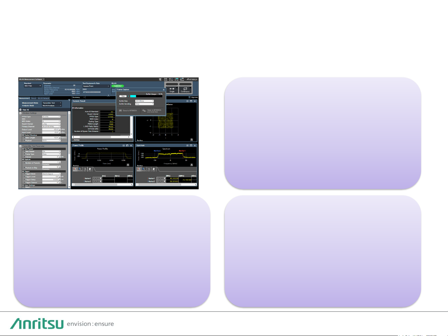
• RF transmit tests are based on IEEE 802.11.
• The headers of packets received from the DUT are analyzed and RF measurements, such as
power, modulation accuracy, spectrum, etc., are performed to display results. Pass/Fail
evaluation of measurement results is performed based on the set reference values.
• At ACK measurement, the MT8862A sends an Test Packet to the DUT; at Data measurement, it
sends a ICMP Echo Request packet. Tx measurement is performed when either the ACK or ICMP
Echo Reply sent from the DUT is received.
• Packets sent using the IP data TRx ports can also be measured.
DUT Tx Test
Page 13

13
DUT Rx Test
• RF receiver tests are based on IEEE 802.11.
• PER/FRR is measured by counting ACK frames sent from DUT in response to Test Packet.
• Configuring a measurement environment is easy by changing power automatically.
• The PER (Packet Error Rate) standard of the Receiver Blocking test in ETSI EN 300 328 V
2.1.1 has been added for broadband wireless devices operating in the 2.4 GHz ISM Band,
including WLAN. This test is done easily using the PER measurement function of the
MT8862A and a signal generator to generate the interference wave.
Page 14

14
• The WLAN Measurement Software MX886200A captures WLAN frames sent to and
received from the DUT. Captured logs can be saved by the PC controller in pcap format for
analysis by software such as Wireshark. This eliminates the need for a separate packet
sniffer to capture WLAN frames and supports troubleshooting of WLAN frames in the RF
measurement environment.
Frame Capture for Troubleshooting DUT Connections
Page 15

15
2x2MIMO Tx Test / Rx Test
• RF Performance of 2x2MIMO signals can be measured by 2 boxes in IEEE802.11n/ac.
• RF Tx test results will be showed by measurement of power and spectrum and analysis a
packet header received from DUT.
• RF Rx test results will be shown as PER and FRR measurement by counting ACK frames.
Page 16

16
• Using the MT8862A, remote-control protocols, such as HiSLIP, VXI11,etc., for controlling
instruments using the general-purpose Raw-Socket connection method, can be selected
to match an existing remote-control environment.
• The same remote-control commands are used for the GUI running on the Web browser
and the GUI remote control command log can also be captured. Creation times are greatly
reduced by using remote-control command sequences.
• In addition, sample sequences are also provided for the SmartStudio Manager
MX847503A for the MT8862A.
Remote Control Environment
1. Making & Selecting test items 2. Run
MX847503A
SmartStudio Manager
Page 17

17
M T 8 8 6 2 A A p p l i c a t i o n s
Page 18

18
Downlink Signal Uplink Signal
OTA Measurements using OTA Chamber
MT8862A
Downlink Signal Uplink Signal
External PC
MT8862A
Anechoic Chamber Reverberation Chamber
• As WLAN applications diversify, WLAN devices and their usage environment are becoming
more complex, resulting in a growing need to quantify and verify that antenna
characteristics meet the design specifications by testing antenna characteristics, such as TX
power range, receiver sensitivity, etc.
• Anritsu supports an OTA measurement test environment with OTA chamber vendors for
measuring the reception power range and receiver sensitivity, such as TRP/TIS, to validate
RF performance in WLAN final-use environments.
External PC
Page 19

19
Regulatory Test
Overview of ETSI Regulatory Test
Originally, the ETSI standard covered tests of transmitted power, spurious emission and etc., which were
measured with power meter and spectrum analyzer. However, "Receiver Blocking Test" has been added
in 2015, so a Signaling Unit or Companion Device is required as the opposing equipment. This test
item requires the calculation of the Packet Error Rate while communicating under the specific conditions
of Minimum Bandwidth and Minimum Data Rate, so the MT8862A Network Mode works effectively.
And, the EMC test, updated in September 2020, also uses PER as an indicator of performance,
increasing the need for Signaling measurement instruments.
Standard Number
RF testing for 2.4 GHz-Band : EN 300 328 V2.2.2
RF testing for 5 GHz-Band : EN 301 893 V2.1.1
EMC testing : EN 301 489-17 V3.2.4
Why MT8862A is better?
Source : EN 300 328 V2.2.2
UUT: Unit Under Test
• Using the Companion Device, it is difficult to
control to a given bandwidth and data rate.
• It's also difficult to measure PER without using
the Signaling Unit.
• It takes a lot of resources and time to build an
environment for communication state control
and communication quality monitoring using
devices other than the Signaling Unit.
Page 20

20
IP Data Transfer
• The Ethernet port on the back panel of the MT8862A can be used for exchanging IP data
with an external server.
• IP connections between the client PC connected to the DUT and the external server
connected to the MT8862A can be checked using the ping function, etc.
• Connections can be checked and RF measurements can be made under fixed parameter
conditions, such as data rate.
• When it is necessary to access a specific server on the Internet at DUT connection, the
MT8862A can also be used for connection maintenance purposes.
• IP Data transfer supports IEEE 802.11a/b/g/n/ac.
External Server
Client PC
Page 21

21
MT8862A measures output power, specified on the radio low, of all frame including connection
attempt period by this function.
Normal mode
Tx Power mode
RF measurement starts after call connection established, with Single/Continuous
buttons. This mode complies with IEEE procedure.
RF measurement starts from before connection established at all frames.
Average Power (Average, Max, Min)
Peak Power (Average, Max, Min)
Crest Factor (Average, Max, Min)
All Frame Power measurement
Purpose: Measure Tx Power before connection is established. Because some devices output max power
during the period.
Target Customer : Smartphone/PC/Tablet, Operators, Automotive, CE, Test House etc
Page 22

22
A p p e n d i x
Page 23

23
MT8862A – Key Specifications
• RF Input/Output: Main 1, Main 2, Aux (Aux: output only)
• Frequency Range: 2.4 to 2.5 GHz, 5.0 to 6.0 GHz (in 1 Hz steps)
• Input Level Range: –65 to +25 dBm (in 0.1 dB steps)
• Output Level Range: –120 to 0 dBm (in 0.1 dB steps)
• Dimensions: 426 (W) × 177 (H) × 390 (D) mm (excluding protruding parts)
• Mass: 14 kg max.
• Power Supply: 100 to 120 Vac/200 to 240 Vac, 50/60 Hz, ≤ 350 VA
• Environmental Conditions: +5°C to +45°C (operating), –20°C to +60°C (storage)
Connectivity Test Set MT8862A
Page 24

24
WLAN Connectivity (1/2)
802.11a
802.11b
802.11g
Frequency
Range
5180 MHz
to 5825 MHz
2412 MHz
to 2484 MHz
2412 MHz
to 2484 MHz
Operation
Mode
- -
ERP
-OFDM
Modulation
OFDM(BPSK,
QPSK,
16QAM, 64 QAM)
DSSS,
CCK
OFDM(BPSK,
QPSK,
16QAM, 64 QAM)
Data Rate
6, 9,
12, 18, 24,
36, 48, 54 Mbps
1, 2, 5.5, 11 Mbps
6, 9,
12, 18, 24,
36, 48, 54 Mbps
Security
*2
WEP, WPA
-Personal, WPA2-Personal
802.11n
802.11ac
*1
Frequency
Range
2412 MHz
to 2484 MHz
5180 MHz
to 5825 MHz
5180 MHz
to 5825 MHz
Bandwidth
20 MHz, 40 MHz
20 MHz, 40 MHz, 80 MHz
MCS
MCS0
to MCS7
MCS0
to MCS9
FEC
BCC
BCC
PPDU Format
HT
-mixed, HT-greenfield
VHT
Guard Interval
Long, Short
Long, Short
RF Chain
Single (SISO), 2x2MIMO
*3
Single (SISO) , 2x2MIMO
*3
Security
*2
WEP, WPA
-Personal, WPA2-Personal
*1: 802.11ac connection requires MX886200A-001.
*2: Secure connections require the MX886200A-020.
*3: 2x2MIMO requires MX886200A-010.
Page 25

25
802.11a
x
*1
Frequency
Range
2412 MHz
to 2484 MHz
5180 MHz
to 5825 MHz
Bandwidth
20 MHz, 40 MHz, 80MHz
MCS
MCS0
to MCS11
FEC
LDPC, BCC
PPDU Format
HE SU, HE TB
GI+ LTF Size
HE_SU:
“
0.8us GI, 1xHE-LTF”, “0.8us GI, 2xHE-LTF”,
“1.6us GI, 2xHE
-LTF”, “0.8us GI, 4xHE-LTF”,“3.2us GI, 4xHE-
LTF”
HE_TB:
“
1.6us GI, 2xHE-LTF”, “3.2us GI, 4xHE-LTF”
RF Chain
Single (SISO)
Security
*2
WEP, WPA
-Personal, WPA2-Personal
WLAN Connectivity (2/2)
*1: 802.11ax connection requires MX886200A-002.
*2: Secure connections require the MX886200A-020.
Page 26

26
Comparison with MT8860C
• Supports 802.11n/ac and AP/STA security connections for more DUT measurements
• Improved usability with separate Tx and Rx RF ports, higher maximum output level, and OTA measurements
• Renewed control software and simpler DUT connection for easier measurement
• Built-in IP data interface for IP continuity tests in reproducible test environment
• Frame capture logs and messaging logging
MT8862A MT8860C
WLAN Connectivity 802.11a/b/g/n/ac/ax 80 MHz bandwidth
SISO / 2x2MIMO
*1
802.11a/b/g 20 MHz bandwidth
SISO
Operating Mode Network mode [AP/STA] Network mode (AP/STA/AdHoc)
Direct mode
Security WEP, WPA-Personal, WPA2-Personal -
RF In/Out Main In/Out (N-Type) x 2
Aux Out (N-Type)
Main In/Out (N-Type)
Interference In, WLAN Ref In (N-Type)
RF Maximum Output
Level
0 dBm [2.4/5 GHz band] –3 dBm [2.4 GHz band]/–8 dBm [5 GHz band]
Control Software Control GUI on web browser LANLook, CombiTest (Windows app)
Remote Interface Ethernet (VXI-11/HiSLIP/Raw) GPIB, Ethernet
Remote Command MT8862A Native MT8860C Native
IP Data Interface Gbit Ethernet
*1
-
Packet Log pcap Output -
Size 1MW 4U 390 mm 3/4MW 4U 350 mm
Red: Additional items, Bold: Changed items
*1: It doesn’t support 11ax.
Page 27

27
HE SU (not OFDMA)
HE SU (not OFDMA)
HE MU (OFDMA)
HE TB (OFDMA)
Single User (STA)
Single User for IoT(DUT)
Multi User(STA)
*PPDU= PLCP Protocol Data Unit
HE SU (not OFDMA)
HE SU(not OFDMA)
*RX test is not defined with IEEE
Single User (AP)
Multi User(AP)
HE ER SU (Not support)
Single User for IoT(AP)
11ax has four frame formats (PPDU format*). MT8862A supports two use cases,
and will add one use case.
Supported status of 11ax
*RX test is not defined with IEEE
Not support
HE ER SU (Not support)
Page 28

28
802.11ax Option Test Coverage
*1: Frequency SPAN of 802.11ax supports up to ±80 MHz
*2: HEMU Tx is not supported
Category Chapter Title Detail
Availability
DUT Measurement Remarks
27.3.14
Transmit
requirements
for an HE TB
PPDU
27.3.14.1
Introduction
- - - - -
27.3.14.2
Power pre
-correction - - - - -
27.3.14.3
Pre
-correction accuracy
requirements
Transmit power and RSSI
measurement accuracy
✔
STA
HETB Tx
-
carrier frequency offset
error
✔
STA
HETB Tx
-
symbol clock error
✔
STA
HETB Tx
-
the arrival time of the HE
TB PPDU at the AP
✔
STA
HETB Tx
Required Signal
Analyzer
27.3.18
Transmit
specification
27.3.18.1
Transmit spectral mask
*1
-
✔
AP/STA
HESU Tx ,HETB Tx, HEMU Tx
*2
-
27.3.18.2
Spectral flatness
-
✔
AP/STA
HESU Tx ,HETB Tx, HEMU Tx
*2
-
27.3.18.3
Transmit center frequency and
symbol clock frequency tolerance
-
✔
AP/STA
HESU Tx ,HETB Tx, HEMU Tx
*2
-
27.3.18.4.1
Introduction to modulation
accuracy tests
- - - - -
27.3.18.4.2
Transmit center frequency leakage
-
✔
AP/STA
HESU Tx ,HETB Tx, HEMU Tx
*2
-
27.3.18.4.3
Transmitter constellation error
-
✔
AP/STA
HESU Tx ,HETB Tx, HEMU Tx
*2
-
27.3.18.4.4
Transmitter modulation accuracy
(EVM) test
-
✔
AP/STA
HESU Tx ,HETB Tx, HEMU Tx
*2
-
27.3.19
Receiver
specification
27.3.19.1
General
- - - - -
27.3.19.2
Receiver minimum input sensitivity
-
✔
AP/STA
HESU Rx
-
27.3.19.3
Adjacent channel rejection
-
✔
AP/STA
HESU Rx
Required Signal
Generator
27.3.19.4
Nonadjacent channel rejection
-
✔
AP/STA
HESU Rx
Required Signal
Generator
27.3.19.5
Receiver maximum input level
-
✔
AP/STA
HESU Rx
-
Page 29

29
MT8862A – RF Input/Output Port Specifications
Main 1
Main 2
Aux
Main/Aux SW
SG
SG/Rx
Auto SW
Rx
Main 1/2 SW
Switch Trigger Output
(Back Panel)
• All ports support output up to 0 dBm for easier configuration of OTA measurement
environment.
• A simple system can be configured even when an external amplifier is required by
separating Tx/Rx using Aux Output.
• DUTs can be switched during measurement by using the Main 1 and Main 2 ports,
supporting automated measurement of multiple DUTs.
• The input level range is –65 to + 25 dBm (Main 1/2).
• The output range is –120 to 0 dBm (Main 1/2 / Aux).
Page 30

30
5 GHz Band DFS testing
WLAN, weather radar, marine radar, etc., use the same frequency bands in the 5.3 GHz
(Ch52-Ch64[W53/U-NII-2A]) and 5.6 GHz bands (Ch100-Ch144[W56/U-NII-2C]), so the
DFS (Dynamic Frequency Selection) technology is used to prevent signal interference
when these signals are detected.
Combining the Vector Signal Generator MG3710E with the waveform pattern product
supports the DFS test defined by TELEC, ETSI, and FCC for 5 GHz band WLAN devices.
DUT
(AP)
Other
device
ATTATT
Vector signal
generator
MG3710E
Spectrum analyzer
/Signal analyzer
MS269xA/MS28xxA
(STA)
Test pulse pattern
Time domain analysis result
Time
Lev.
Time
Lev.
AP
Radar
No signal
PC
(iperf server)
PC
(iperf client)
Page 31

31
Documents and Firmware Web Downloads
• Anritsu Web Site
– Download catalogs, product introduction, etc.
– Open access by anyone
https://www.anritsu.com/en-GB/test-measurement/products/mt8862a
• My Anritsu
– Download operation manuals, firmware, tools, etc.
– Requires creation of My Anritsu account and
product registration
https://login.anritsu.com/signin?
Page 32

2021-1 MJM No. MT8862A-E-L-1-(8.00)
 Loading...