

Page 1

MT8852B
Bluetooth Test Set
Remote Programming Manual
Seventh Edition
● For safety and warning information, please read this
manual before attempting to use the equipment.
● Additional safety and warning information is provided
within the MT8852B Bluetooth Test Set Operation
Manual. Please also refer to it before using the
equipment.
● Keep this manual with the equipment.
ANRITSU CORPORATION
Document No.: M-W3969AE-7.0
Page 2

Safety Symbols
DANGER
WARNING
CAUTION
To prevent the risk of personal injury or loss related to equipment malfunction, Anritsu
Corporation uses the following safety symbols to indicate safety-related information. Ensure
that you clearly understand the meanings of the symbols BEFORE using the equipment.
Some or all of the following symbols may be used on all Anritsu equipment. In addition, there
may be other labels attached to products that are not shown in the diagrams in this manual.
Symbols Used in Manuals
This indicates a very dangerous procedure that could
result in serious injury or death if not performed properly.
This indicates a hazardous procedure that could result in
serious injury or death if not performed properly.
This indicates a hazardous procedure or danger that could
result in light-to-severe injury, or loss related to equipment
malfunction, if proper precautions are not taken.
Safety Symbols Used on Equipment and in Manuals
The following safety symbols are used inside or on the equipment near operation locations to
provide information about safety items and operation precautions. Ensure that you clearly
understand the meanings of the symbols and take the necessary precautions BEFORE using
the equipment.
This indicates a prohibited operation. The prohibited operation is indicated
symbolically in or near the barred circle.
This indicates a compulsory safety precaution. The required operation is indicated
symbolically in or near the circle.
This indicates a warning or caution. The contents are indicated symbolically in or
near the triangle.
This indicates a note. The contents are described in the box.
These indicate that the marked part should be recycled.
MT8852B
Bluetooth Tes t S et
Remote Programming Manual
11 May 2018 (First Edition)
15 December 2020 (Seventh Edition)
Copyright © 2018-2020, ANRITSU CORPORATION.
All rights reserved. No part of this manual may be reproduced without the prior written permission
of the publisher.
The operational instructions of this manual may be changed without prior notice.
Printed in Japan
Safety-2
Page 3

Notes On Export Management
This product and its manuals may require an Export License/
Approval by the Government of the product's country of origin
for re-export from your country.
Before re-exporting the product or manuals, please contact us
to confirm whether they are export-controlled items or not.
When you dispose of export-controlled items, the products/
manuals need to be broken/shredded so as not to be
unlawfully used for military purpose.
Safety-3
Page 4

Safety-4
Page 5

Table of Contents
Chapter 1—General Information
1-1 About this Manual . . . . . . . . . . . . . . . . . . . . . . . . . . . . . . . . . . . . . . . . . . . . . . . . . 1-1
Comments on this Manual. . . . . . . . . . . . . . . . . . . . . . . . . . . . . . . . . . . . . . . . 1-1
Software Versions . . . . . . . . . . . . . . . . . . . . . . . . . . . . . . . . . . . . . . . . . . . . . . 1-1
Notification of Software Release . . . . . . . . . . . . . . . . . . . . . . . . . . . . . . . . . . . 1-2
Associated Documentation . . . . . . . . . . . . . . . . . . . . . . . . . . . . . . . . . . . . . . . 1-2
Conventions. . . . . . . . . . . . . . . . . . . . . . . . . . . . . . . . . . . . . . . . . . . . . . . . . . . 1-2
1-2 Command Format. . . . . . . . . . . . . . . . . . . . . . . . . . . . . . . . . . . . . . . . . . . . . . . . . 1-3
Chapter 2—GPIB Overview
2-1 Requirements when using GPIB. . . . . . . . . . . . . . . . . . . . . . . . . . . . . . . . . . . . . . 2-1
2-2 Syntax. . . . . . . . . . . . . . . . . . . . . . . . . . . . . . . . . . . . . . . . . . . . . . . . . . . . . . . . . . 2-1
2-3 Termination. . . . . . . . . . . . . . . . . . . . . . . . . . . . . . . . . . . . . . . . . . . . . . . . . . . . . . 2-2
2-4 Suffixes . . . . . . . . . . . . . . . . . . . . . . . . . . . . . . . . . . . . . . . . . . . . . . . . . . . . . . . . . 2-2
2-5 GPIB 488.2 Registers . . . . . . . . . . . . . . . . . . . . . . . . . . . . . . . . . . . . . . . . . . . . . . 2-3
Status Byte Register and Service Request Enable Register. . . . . . . . . . . . . . 2-3
Standard Event Status Register and Standard Event Status Enable Register 2-5
EUT Fail Register and Fail Enable Register . . . . . . . . . . . . . . . . . . . . . . . . . . 2-6
Instrument Status Register and Instrument Status Enable Register . . . . . . . . 2-7
Change Register and Change Enable Register . . . . . . . . . . . . . . . . . . . . . . . 2-8
EDR EUT Fail Register and EDR EUT Fail Enable Register . . . . . . . . . . . . . 2-9
2nd EDR EUT Fail Register and 2nd EDR EUT Fail Enable Register . . . . . 2-10
BLE EUT Fail Register and BLE EUT Fail Enable Register . . . . . . . . . . . . . 2-11
2-6 GPIB over RS232 . . . . . . . . . . . . . . . . . . . . . . . . . . . . . . . . . . . . . . . . . . . . . . . . 2-12
2-7 Summary of RS232 Commands . . . . . . . . . . . . . . . . . . . . . . . . . . . . . . . . . . . . . 2-13
Chapter 3—IEEE 488.2 Mandatory and Register Commands
*CHE (Change Enable Register) . . . . . . . . . . . . . . . . . . . . . . . . . . . . . . . . . . . 3-1
*CHG (Change Register). . . . . . . . . . . . . . . . . . . . . . . . . . . . . . . . . . . . . . . . . 3-1
*CLS (Clear GPIB Status Bytes) . . . . . . . . . . . . . . . . . . . . . . . . . . . . . . . . . . . 3-2
*EETE (EDR EUT Fail Enable Register) . . . . . . . . . . . . . . . . . . . . . . . . . . . . . 3-2
*EETE2 (2nd EDR EUT Fail Enable Register) . . . . . . . . . . . . . . . . . . . . . . . . 3-3
*EETF (EDR EUT Fail Register Query) . . . . . . . . . . . . . . . . . . . . . . . . . . . . . . 3-4
*EETF2 (2nd EDR EUT Fail Register Query) . . . . . . . . . . . . . . . . . . . . . . . . . 3-4
*ESE (Standard Event Status Enable) . . . . . . . . . . . . . . . . . . . . . . . . . . . . . . 3-5
*ESR (Standard Event Status Register Query) . . . . . . . . . . . . . . . . . . . . . . . . 3-6
*ETE (EUT Fail Enable Register) . . . . . . . . . . . . . . . . . . . . . . . . . . . . . . . . . . 3-6
*ETF (EUT Fail Register Query) . . . . . . . . . . . . . . . . . . . . . . . . . . . . . . . . . . . 3-7
*IDN (Identification Query). . . . . . . . . . . . . . . . . . . . . . . . . . . . . . . . . . . . . . . . 3-7
Contents-1
Page 6

*INE (Instrument Status Enable Register) . . . . . . . . . . . . . . . . . . . . . . . . . . . . 3-8
*INS (Instrument Status Register Query). . . . . . . . . . . . . . . . . . . . . . . . . . . . . 3-8
*LEETE (BLE EUT Fail Enable Register) . . . . . . . . . . . . . . . . . . . . . . . . . . . . 3-9
*LEETF (BLE EUT Fail Register Query) . . . . . . . . . . . . . . . . . . . . . . . . . . . . . 3-9
*OPC (Operation Completed Indication) . . . . . . . . . . . . . . . . . . . . . . . . . . . . 3-10
*RST (Instrument Reset) . . . . . . . . . . . . . . . . . . . . . . . . . . . . . . . . . . . . . . . . 3-10
*SRE (Service Request Enable Register) . . . . . . . . . . . . . . . . . . . . . . . . . . . 3-11
*STB (Status Byte Register Query) . . . . . . . . . . . . . . . . . . . . . . . . . . . . . . . . 3-11
*TST (Self Test Query) . . . . . . . . . . . . . . . . . . . . . . . . . . . . . . . . . . . . . . . . . 3-12
*WAI (Wait to Continue). . . . . . . . . . . . . . . . . . . . . . . . . . . . . . . . . . . . . . . . . 3-12
Chapter 4—General GPIB Commands
BOOTSTATUS? (Startup Self Test Status Request ) . . . . . . . . . . . . . . . . . . . 4-1
CONT (Continue After Self Test) . . . . . . . . . . . . . . . . . . . . . . . . . . . . . . . . . . . 4-1
ERRLST (Error List). . . . . . . . . . . . . . . . . . . . . . . . . . . . . . . . . . . . . . . . . . . . . 4-2
EUTINIT (Bluetooth Peripheral Mode). . . . . . . . . . . . . . . . . . . . . . . . . . . . . . . 4-4
EUTMAXPWR (Send EUT to Max Power Control) . . . . . . . . . . . . . . . . . . . . . 4-4
LECTETIME (Set the CTE time) . . . . . . . . . . . . . . . . . . . . . . . . . . . . . . . . . . . 4-4
LECTETIMEMODE (Set the CTE time mode) . . . . . . . . . . . . . . . . . . . . . . . . . 4-5
LEPKTLEN (Set the BLE data packet length) . . . . . . . . . . . . . . . . . . . . . . . . . 4-6
LEPKTMODE (Set the BLE data packet mode) . . . . . . . . . . . . . . . . . . . . . . . 4-6
LKPASS (Update Lock/Unlock Password) . . . . . . . . . . . . . . . . . . . . . . . . . . . 4-7
LOCK (Script Lock) . . . . . . . . . . . . . . . . . . . . . . . . . . . . . . . . . . . . . . . . . . . . . 4-7
OPMD (Operation Mode). . . . . . . . . . . . . . . . . . . . . . . . . . . . . . . . . . . . . . . . . 4-8
OPTSTATUS? (Option Status) . . . . . . . . . . . . . . . . . . . . . . . . . . . . . . . . . . . 4-10
SCPTCFG (Configure Script) . . . . . . . . . . . . . . . . . . . . . . . . . . . . . . . . . . . . 4-10
SCPTNM (Set Script Name) . . . . . . . . . . . . . . . . . . . . . . . . . . . . . . . . . . . . . 4-14
SCPTRST (Reset Script) . . . . . . . . . . . . . . . . . . . . . . . . . . . . . . . . . . . . . . . . 4-15
SCPTSEL (Select Script). . . . . . . . . . . . . . . . . . . . . . . . . . . . . . . . . . . . . . . . 4-15
SCPTTSTGP (Set Test Group State) . . . . . . . . . . . . . . . . . . . . . . . . . . . . . . 4-15
SCRIPTMODE (Script Mode) . . . . . . . . . . . . . . . . . . . . . . . . . . . . . . . . . . . . 4-16
STATUS (Status Command) . . . . . . . . . . . . . . . . . . . . . . . . . . . . . . . . . . . . . 4-17
STERR (Request POST or *TST? Results). . . . . . . . . . . . . . . . . . . . . . . . . . 4-19
Self Test Items. . . . . . . . . . . . . . . . . . . . . . . . . . . . . . . . . . . . . . . . . . . . . . . . 4-19
TSTPAUSE (Test Pause) . . . . . . . . . . . . . . . . . . . . . . . . . . . . . . . . . . . . . . . 4-21
TXPWR (Transmitter Power Level) . . . . . . . . . . . . . . . . . . . . . . . . . . . . . . . . 4-21
UNLOCK (Script Unlock) . . . . . . . . . . . . . . . . . . . . . . . . . . . . . . . . . . . . . . . . 4-22
Chapter 5—System Configuration
SYSCFG (Set or Query System Configuration) . . . . . . . . . . . . . . . . . . . . . . . . 5-1
AUTH (Authentication Settings) . . . . . . . . . . . . . . . . . . . . . . . . . . . . . . . . . . . . 5-2
BNCOUTPUT (Rear Panel Output) . . . . . . . . . . . . . . . . . . . . . . . . . . . . . . . . . 5-3
BTADDR (Tester Bluetooth Address) . . . . . . . . . . . . . . . . . . . . . . . . . . . . . . . 5-4
CONFIG (Tester Configuration) . . . . . . . . . . . . . . . . . . . . . . . . . . . . . . . . . . . . 5-5
Contents-2
Page 7

DISPSOUND (Tester Display and Sound Control) . . . . . . . . . . . . . . . . . . . . 5-11
EUTADDR (EUT Address) . . . . . . . . . . . . . . . . . . . . . . . . . . . . . . . . . . . . . . 5-15
EUTFEAT (EUT supported features). . . . . . . . . . . . . . . . . . . . . . . . . . . . . . . 5-15
EUTHANDSHAKE (EUT RS232 handshake setting) . . . . . . . . . . . . . . . . . . 5-16
EUTLEFEAT (EUT supported features for Low energy) . . . . . . . . . . . . . . . . 5-16
EUTNAME (EUT User Friendly Name Request) . . . . . . . . . . . . . . . . . . . . . . 5-17
EUTRS232 (EUT RS232 HCI Set Up). . . . . . . . . . . . . . . . . . . . . . . . . . . . . . 5-17
EUTSRCE (EUT Address Source) . . . . . . . . . . . . . . . . . . . . . . . . . . . . . . . . 5-18
HWINFO (Hardware information) . . . . . . . . . . . . . . . . . . . . . . . . . . . . . . . . . 5-19
IDENT (Tester Identity) . . . . . . . . . . . . . . . . . . . . . . . . . . . . . . . . . . . . . . . . . 5-19
INQSET (Inquiry Set Up) . . . . . . . . . . . . . . . . . . . . . . . . . . . . . . . . . . . . . . . . 5-20
PAGSET (Page Setting) . . . . . . . . . . . . . . . . . . . . . . . . . . . . . . . . . . . . . . . . 5-22
SCPTSET (Script Set Up) . . . . . . . . . . . . . . . . . . . . . . . . . . . . . . . . . . . . . . . 5-23
USBADAPTOR (Adaptor Set Up) . . . . . . . . . . . . . . . . . . . . . . . . . . . . . . . . . 5-25
VERDATE (Tester Firmware Version and Date Stamp) . . . . . . . . . . . . . . . . 5-26
VERNUM (Tester Firmware Version Numbers). . . . . . . . . . . . . . . . . . . . . . . 5-26
Chapter 6—SCO Configuration
SCOCFG (Set SCO Configuration) . . . . . . . . . . . . . . . . . . . . . . . . . . . . . . . . . 6-1
Chapter 7—SCO Connections
SCOCONN (SCO Connect). . . . . . . . . . . . . . . . . . . . . . . . . . . . . . . . . . . . . . . 7-1
SCODISC (SCO Disconnect) . . . . . . . . . . . . . . . . . . . . . . . . . . . . . . . . . . . . . 7-1
Chapter 8—AFH Measurement
AFHCFG (Set AFH Configuration) . . . . . . . . . . . . . . . . . . . . . . . . . . . . . . . . . 8-1
Chapter 9—Signal Generator Mode and CW Measurement
Basic Rate Signal Generator Mode . . . . . . . . . . . . . . . . . . . . . . . . . . . . . . . . . 9-1
BLE Signal Generator Mode . . . . . . . . . . . . . . . . . . . . . . . . . . . . . . . . . . . . . . 9-2
BLE Extended Signal Generator Mode (Supports Data Length Extension) . . 9-3
BLE Extended Signal Generator Mode (Supports Bluetooth 5 - 2LE and BLR)9-4
BLE Extended Signal Generator Mode (Supports Bluetooth 5.1 - Constant Tone
Contents-3
Page 8

Extension) . . . . . . . . . . . . . . . . . . . . . . . . . . . . . . . . . . . . . . . . . . . . . . . . . . . . 9-6
EDR Signal Generator Mode . . . . . . . . . . . . . . . . . . . . . . . . . . . . . . . . . . . . . . 9-8
CW Measurement Mode . . . . . . . . . . . . . . . . . . . . . . . . . . . . . . . . . . . . . . . . . 9-9
EDR CW Measurement Mode . . . . . . . . . . . . . . . . . . . . . . . . . . . . . . . . . . . . 9-10
CWRESULT (CW Measurements Results Output) . . . . . . . . . . . . . . . . . . . . 9-11
ECWRESULT (EDR CW Measurements Results Output). . . . . . . . . . . . . . . 9-12
Chapter 10—Configuring Tests in Standard Mode
10-1 Basic Rate Tests. . . . . . . . . . . . . . . . . . . . . . . . . . . . . . . . . . . . . . . . . . . . . . . . . 10-3
Output Power Test Configuration (OPCFG) . . . . . . . . . . . . . . . . . . . . . . . . . 10-3
Power Control Test Configuration (PCCFG) . . . . . . . . . . . . . . . . . . . . . . . . . 10-5
Enhanced Power Control Test Configuration (EPCCFG) . . . . . . . . . . . . . . . 10-7
Initial Carrier Test Configuration (ICCFG) . . . . . . . . . . . . . . . . . . . . . . . . . . . 10-9
Carrier Drift Test Configuration (CDCFG) . . . . . . . . . . . . . . . . . . . . . . . . . . 10-11
Single Slot Sensitivity Test Configuration (SSCFG) . . . . . . . . . . . . . . . . . . 10-13
Multi Slot Sensitivity Test Configuration (MSCFG) . . . . . . . . . . . . . . . . . . . 10-15
Modulation Index Test Configuration (MICFG) . . . . . . . . . . . . . . . . . . . . . . 10-17
Input Power Sensitivity Test Configuration (MPCFG) . . . . . . . . . . . . . . . . . 10-19
10-2 Enhanced Data Rate Tests. . . . . . . . . . . . . . . . . . . . . . . . . . . . . . . . . . . . . . . . 10-21
Relative Transmit Power Test Configuration (ERPCFG). . . . . . . . . . . . . . . 10-21
Carrier Frequency Stability and Modulation Test Configuration (ECMCFG) 10-23
Differential Phase Encoding Test Configuration (EDPCFG) . . . . . . . . . . . . 10-26
EDR Sensitivity Test Configuration (EBSCFG) . . . . . . . . . . . . . . . . . . . . . . 10-28
EDR BER Floor Sensitivity Test Configuration (EFSCFG) . . . . . . . . . . . . . 10-30
EDR Maximum Input Power Test Configuration (EMPCFG) . . . . . . . . . . . . 10-32
EDR Guard Time Test Configuration (EGTCFG) . . . . . . . . . . . . . . . . . . . . 10-34
EDR Synchronization Sequence and Trailer Test Configuration (ESTCFG)10-36
10-3 Low Energy Tests . . . . . . . . . . . . . . . . . . . . . . . . . . . . . . . . . . . . . . . . . . . . . . . 10-38
BLE Output Power Test Configuration (LEOPCFG) . . . . . . . . . . . . . . . . . . 10-38
BLE Carrier Frequency Offset and Drift Test Configuration (LEICDCFG). . 10-40
BLE Modulation Characteristics Test Configuration (LEMICFG). . . . . . . . . 10-43
BLE Tx Power Stability Test Configuration (LEPSCFG) . . . . . . . . . . . . . . . 10-46
BLE Receiver Sensitivity Test Configuration (LESSCFG) . . . . . . . . . . . . . . 10-48
BLE PER Report Integrity (LEPRICFG). . . . . . . . . . . . . . . . . . . . . . . . . . . . 10-50
BLE Maximum Input Signal Level Test Configuration (LEMPCFG). . . . . . . 10-52
Chapter 11—Configuring Tests in Single Payload Mode
11-1 Single Payload Configuration (SPCFG) . . . . . . . . . . . . . . . . . . . . . . . . . . . . . . . 11-1
Chapter 12—Test Parameter Variables
Actual Frequencies Used. . . . . . . . . . . . . . . . . . . . . . . . . . . . . . . . . . . . . . . . 12-1
ANTSWLIST . . . . . . . . . . . . . . . . . . . . . . . . . . . . . . . . . . . . . . . . . . . . . . . . . 12-4
ANTSWPAT. . . . . . . . . . . . . . . . . . . . . . . . . . . . . . . . . . . . . . . . . . . . . . . . . . 12-4
CTESLOT . . . . . . . . . . . . . . . . . . . . . . . . . . . . . . . . . . . . . . . . . . . . . . . . . . . 12-5
Contents-4
Page 9

DEFAULT . . . . . . . . . . . . . . . . . . . . . . . . . . . . . . . . . . . . . . . . . . . . . . . . . . . 12-5
DHXPKT . . . . . . . . . . . . . . . . . . . . . . . . . . . . . . . . . . . . . . . . . . . . . . . . . . . . 12-6
DIRTYTAB. . . . . . . . . . . . . . . . . . . . . . . . . . . . . . . . . . . . . . . . . . . . . . . . . . . 12-7
DIRTYTX . . . . . . . . . . . . . . . . . . . . . . . . . . . . . . . . . . . . . . . . . . . . . . . . . . . . 12-8
Frequencies Used (LFREQSEL, MFREQSEL, HFREQSEL) . . . . . . . . . . . . 12-9
DRIFTS . . . . . . . . . . . . . . . . . . . . . . . . . . . . . . . . . . . . . . . . . . . . . . . . . . . . 12-10
FERLIMMODE. . . . . . . . . . . . . . . . . . . . . . . . . . . . . . . . . . . . . . . . . . . . . . . 12-10
HOPMODE . . . . . . . . . . . . . . . . . . . . . . . . . . . . . . . . . . . . . . . . . . . . . . . . . 12-11
HOPPING . . . . . . . . . . . . . . . . . . . . . . . . . . . . . . . . . . . . . . . . . . . . . . . . . . 12-12
HOPSTATE . . . . . . . . . . . . . . . . . . . . . . . . . . . . . . . . . . . . . . . . . . . . . . . . . 12-13
LEPKTTYPE . . . . . . . . . . . . . . . . . . . . . . . . . . . . . . . . . . . . . . . . . . . . . . . . 12-14
MINCHECK . . . . . . . . . . . . . . . . . . . . . . . . . . . . . . . . . . . . . . . . . . . . . . . . . 12-16
MINPWR . . . . . . . . . . . . . . . . . . . . . . . . . . . . . . . . . . . . . . . . . . . . . . . . . . . 12-17
NUMANT . . . . . . . . . . . . . . . . . . . . . . . . . . . . . . . . . . . . . . . . . . . . . . . . . . . 12-17
NUMANTMODE . . . . . . . . . . . . . . . . . . . . . . . . . . . . . . . . . . . . . . . . . . . . . 12-18
NUMBITS . . . . . . . . . . . . . . . . . . . . . . . . . . . . . . . . . . . . . . . . . . . . . . . . . . 12-18
NUMBLKS . . . . . . . . . . . . . . . . . . . . . . . . . . . . . . . . . . . . . . . . . . . . . . . . . . 12-19
NUMCYC. . . . . . . . . . . . . . . . . . . . . . . . . . . . . . . . . . . . . . . . . . . . . . . . . . . 12-19
NUMPKTS . . . . . . . . . . . . . . . . . . . . . . . . . . . . . . . . . . . . . . . . . . . . . . . . . . 12-20
PAYLOAD . . . . . . . . . . . . . . . . . . . . . . . . . . . . . . . . . . . . . . . . . . . . . . . . . . 12-21
PKTCOUNT. . . . . . . . . . . . . . . . . . . . . . . . . . . . . . . . . . . . . . . . . . . . . . . . . 12-21
PKTNUMMODE. . . . . . . . . . . . . . . . . . . . . . . . . . . . . . . . . . . . . . . . . . . . . . 12-22
PKTSIZE . . . . . . . . . . . . . . . . . . . . . . . . . . . . . . . . . . . . . . . . . . . . . . . . . . . 12-23
PKTTYPE . . . . . . . . . . . . . . . . . . . . . . . . . . . . . . . . . . . . . . . . . . . . . . . . . . 12-24
PTXLEV. . . . . . . . . . . . . . . . . . . . . . . . . . . . . . . . . . . . . . . . . . . . . . . . . . . . 12-25
PWRDELAY . . . . . . . . . . . . . . . . . . . . . . . . . . . . . . . . . . . . . . . . . . . . . . . . 12-25
SWPATLEN. . . . . . . . . . . . . . . . . . . . . . . . . . . . . . . . . . . . . . . . . . . . . . . . . 12-26
THBITCNT. . . . . . . . . . . . . . . . . . . . . . . . . . . . . . . . . . . . . . . . . . . . . . . . . . 12-26
TOGGLE . . . . . . . . . . . . . . . . . . . . . . . . . . . . . . . . . . . . . . . . . . . . . . . . . . . 12-27
TSTCTRL . . . . . . . . . . . . . . . . . . . . . . . . . . . . . . . . . . . . . . . . . . . . . . . . . . 12-28
TTBITCNT . . . . . . . . . . . . . . . . . . . . . . . . . . . . . . . . . . . . . . . . . . . . . . . . . . 12-29
TXPWR . . . . . . . . . . . . . . . . . . . . . . . . . . . . . . . . . . . . . . . . . . . . . . . . . . . . 12-29
TXPWRLR2 . . . . . . . . . . . . . . . . . . . . . . . . . . . . . . . . . . . . . . . . . . . . . . . . . 12-30
TXPWRLR8 . . . . . . . . . . . . . . . . . . . . . . . . . . . . . . . . . . . . . . . . . . . . . . . . . 12-30
Chapter 13—Test Limit Variables
13-1 Output Power Test Limit Commands . . . . . . . . . . . . . . . . . . . . . . . . . . . . . . . . . 13-1
13-2 Power Control Test Limit Commands . . . . . . . . . . . . . . . . . . . . . . . . . . . . . . . . . 13-2
13-3 Enhanced Power Control Test Limit Commands . . . . . . . . . . . . . . . . . . . . . . . . 13-3
13-4 Initial Carrier Frequency Test Limit Commands . . . . . . . . . . . . . . . . . . . . . . . . . 13-4
13-5 Carrier Frequency Drift Limit Commands . . . . . . . . . . . . . . . . . . . . . . . . . . . . . . 13-5
13-6 Standard Rate Sensitivity Test Limit Commands . . . . . . . . . . . . . . . . . . . . . . . . 13-6
Contents-5
Page 10

13-7 Modulation Index Limit Commands. . . . . . . . . . . . . . . . . . . . . . . . . . . . . . . . . . . 13-7
13-8 EDR Relative Transmit Power Limit Commands . . . . . . . . . . . . . . . . . . . . . . . . 13-8
13-9 EDR Carrier Frequency and Accuracy Limit Commands . . . . . . . . . . . . . . . . . 13-10
13-10 EDR Differential Phase Encoding Limit Commands. . . . . . . . . . . . . . . . . . . . . 13-17
13-11 EDR Sensitivity and EDR BER Floor Limit Commands . . . . . . . . . . . . . . . . . . 13-18
13-12 EDR Maximum Input Power Limits . . . . . . . . . . . . . . . . . . . . . . . . . . . . . . . . . . 13-20
13-13 EDR Guard Time Limit Commands . . . . . . . . . . . . . . . . . . . . . . . . . . . . . . . . . 13-21
13-14 EDR Synchronization Sequence and Trailer Limit Commands . . . . . . . . . . . . 13-22
13-15 BLE Output Power Test Limit Commands . . . . . . . . . . . . . . . . . . . . . . . . . . . . 13-23
13-16 BLE Carrier Frequency Offset and Drift Limit Commands . . . . . . . . . . . . . . . . 13-25
13-17 BLE Modulation Characteristics Limit Commands . . . . . . . . . . . . . . . . . . . . . . 13-28
13-18 BLE Tx Power Stability Limit Commands . . . . . . . . . . . . . . . . . . . . . . . . . . . . . 13-30
13-19 BLE Sensitivity Test and Maximum Input Limit Commands . . . . . . . . . . . . . . . 13-31
13-20 BLE PER Report Integrity Test Limit Commands . . . . . . . . . . . . . . . . . . . . . . . 13-32
Chapter 14—Running and Aborting Code
Running Tests (RUN) . . . . . . . . . . . . . . . . . . . . . . . . . . . . . . . . . . . . . . . . . . 14-1
Aborting Tests (ABORT) . . . . . . . . . . . . . . . . . . . . . . . . . . . . . . . . . . . . . . . . 14-1
Chapter 15—Reading Test Results Data
15-1 Summary Results . . . . . . . . . . . . . . . . . . . . . . . . . . . . . . . . . . . . . . . . . . . . . . . . 15-2
15-2 Summary Results Output Format . . . . . . . . . . . . . . . . . . . . . . . . . . . . . . . . . . . 15-4
15-3 Extended Results Data Output . . . . . . . . . . . . . . . . . . . . . . . . . . . . . . . . . . . . . . 15-7
15-4 Extended Results Output Format . . . . . . . . . . . . . . . . . . . . . . . . . . . . . . . . . . . 15-10
15-5 Basic Rate Tests. . . . . . . . . . . . . . . . . . . . . . . . . . . . . . . . . . . . . . . . . . . . . . . . 15-13
Output Power Test Results . . . . . . . . . . . . . . . . . . . . . . . . . . . . . . . . . . . . . 15-13
Power Control Test Results . . . . . . . . . . . . . . . . . . . . . . . . . . . . . . . . . . . . . 15-14
Enhanced Power Control Test Results . . . . . . . . . . . . . . . . . . . . . . . . . . . . 15-15
Modulation Index Test Results . . . . . . . . . . . . . . . . . . . . . . . . . . . . . . . . . . 15-18
Initial Carrier Test Results . . . . . . . . . . . . . . . . . . . . . . . . . . . . . . . . . . . . . . 15-19
Carrier Drift Test Results . . . . . . . . . . . . . . . . . . . . . . . . . . . . . . . . . . . . . . . 15-20
Single Slot Sensitivity Test Results . . . . . . . . . . . . . . . . . . . . . . . . . . . . . . . 15-22
Multi Slot Sensitivity Test Results . . . . . . . . . . . . . . . . . . . . . . . . . . . . . . . . 15-24
Maximum Input Power Test Results . . . . . . . . . . . . . . . . . . . . . . . . . . . . . . 15-25
15-6 EDR Tests. . . . . . . . . . . . . . . . . . . . . . . . . . . . . . . . . . . . . . . . . . . . . . . . . . . . . 15-26
EDR Relative Transmit Power Test Results . . . . . . . . . . . . . . . . . . . . . . . . 15-26
EDR Carrier Frequency Stability and Modulation Accuracy Test Results . . 15-29
EDR Differential Phase Encoding Test Results . . . . . . . . . . . . . . . . . . . . . . 15-32
EDR Sensitivity Test Results . . . . . . . . . . . . . . . . . . . . . . . . . . . . . . . . . . . . 15-34
BER Floor Sensitivity Test Results . . . . . . . . . . . . . . . . . . . . . . . . . . . . . . . 15-37
Contents-6
Page 11

Maximum Input Power Test Results . . . . . . . . . . . . . . . . . . . . . . . . . . . . . . 15-40
EDR Guard Time Test Results . . . . . . . . . . . . . . . . . . . . . . . . . . . . . . . . . . 15-43
EDR Synchronization Sequence and Trailer Test Results . . . . . . . . . . . . . 15-45
15-7 Low Energy Tests . . . . . . . . . . . . . . . . . . . . . . . . . . . . . . . . . . . . . . . . . . . . . . . 15-47
BLE Output Power Test Results . . . . . . . . . . . . . . . . . . . . . . . . . . . . . . . . . 15-47
BLE Carrier Frequency Offset and Drift Test Results . . . . . . . . . . . . . . . . . 15-48
BLE Modulation Characteristics Test Results . . . . . . . . . . . . . . . . . . . . . . . 15-50
BLE Tx Power Stability Test Results . . . . . . . . . . . . . . . . . . . . . . . . . . . . . . 15-52
BLE Receiver Sensitivity Test Results . . . . . . . . . . . . . . . . . . . . . . . . . . . . 15-54
BLE PER Report Integrity Test Results. . . . . . . . . . . . . . . . . . . . . . . . . . . . 15-55
BLE Maximum Input Signal Level Test Results. . . . . . . . . . . . . . . . . . . . . . 15-56
Chapter 16—BLE Measurement
ABORTCAP Abort the BLE Measurement Capture. . . . . . . . . . . . . . . . . . . . 16-1
CFGBLECAP (Configure BLE Capture) . . . . . . . . . . . . . . . . . . . . . . . . . . . 16-1
LESCPTCFG (Configure all measurements in a script in parallel) . . . . . . . . 16-2
MEASBLECAP (Capture and Make BLE Tx Measurement) . . . . . . . . . . . . . 16-4
MEASBLECAPX (Capture and Make BLE Tx Measurement - Extended). . . 16-5
MEASBLECAPX2 (Capture and Make BLE Tx Measurement - Extended for CTE)
Contents-7
Page 12

16-6
SETBLECAPTYP (Set the capture type to BLE, 2LE or BLR). . . . . . . . . . . . 16-8
Example BLE Measurement . . . . . . . . . . . . . . . . . . . . . . . . . . . . . . . . . . . . . 16-9
Chapter 17—Auxiliary Commands
CONNECT (Connect to EUT Address) . . . . . . . . . . . . . . . . . . . . . . . . . . . . . 17-2
CONEUTNAME (Read EUT User Name on a Connection). . . . . . . . . . . . . . 17-2
CONNPKT (Connection packet control) . . . . . . . . . . . . . . . . . . . . . . . . . . . . 17-3
CONTIME? (Connection time) (Option 15 required) . . . . . . . . . . . . . . . . . . . 17-3
DISCONNECT (Disconnect From Device) . . . . . . . . . . . . . . . . . . . . . . . . . . 17-4
EUTRESET (Send HCI Reset to the DUT) . . . . . . . . . . . . . . . . . . . . . . . . . . 17-4
EUTRMTPWR (Change the State of the EUT Tx Power) . . . . . . . . . . . . . . . 17-4
EUTVENDCMD (Send a Vendor-Specific Command to EUT) . . . . . . . . . . . 17-5
FIXEDOFF (Set Fixed Offset Value) . . . . . . . . . . . . . . . . . . . . . . . . . . . . . . . 17-7
GETEUTFEAT (Obtain Supported Features from EUT) . . . . . . . . . . . . . . . . 17-7
INQCANCEL (Cancel an Inquiry) . . . . . . . . . . . . . . . . . . . . . . . . . . . . . . . . . 17-7
INQRSP? (Obtain the Results of an Inquiry) . . . . . . . . . . . . . . . . . . . . . . . . . 17-8
INQUIRY (Perform an Inquiry) . . . . . . . . . . . . . . . . . . . . . . . . . . . . . . . . . . . . 17-8
LOOPBACK (Perform a Loopback Test Control Sequence) . . . . . . . . . . . . . 17-9
PATHDEL (Delete an Entry from a Path Loss Table) . . . . . . . . . . . . . . . . . 17-10
PATHEDIT (Add or Change Entries in a Path Loss Table) . . . . . . . . . . . . . 17-10
PATHOFF (Set Path Offset Mode) . . . . . . . . . . . . . . . . . . . . . . . . . . . . . . . 17-11
PATHRD (Read a Complete Path Loss Table) . . . . . . . . . . . . . . . . . . . . . . 17-11
PATHTBL (Set Path Offset Table) . . . . . . . . . . . . . . . . . . . . . . . . . . . . . . . . 17-12
PATHTBLCLR (Clear a User Path Table) . . . . . . . . . . . . . . . . . . . . . . . . . . 17-12
TESTMODE (Put the EUT into Test Mode) . . . . . . . . . . . . . . . . . . . . . . . . . 17-12
TSTDELAY (Test Control Delay) . . . . . . . . . . . . . . . . . . . . . . . . . . . . . . . . . 17-13
TXTEST (Perform a Tx Test Control Sequence) . . . . . . . . . . . . . . . . . . . . . 17-14
WRDTY (Write the Dirty Parameter Settings to the Core). . . . . . . . . . . . . . 17-14
Appendix A—Supported Features Format
A-1 EUT Feature Format . . . . . . . . . . . . . . . . . . . . . . . . . . . . . . . . . . . . . . . . . . . . . . . A-1
Appendix B—GPIB PC Card Set-up
B-1 GPIB Card Settings. . . . . . . . . . . . . . . . . . . . . . . . . . . . . . . . . . . . . . . . . . . . . . . . B-1
B-2 GPIB Device Template . . . . . . . . . . . . . . . . . . . . . . . . . . . . . . . . . . . . . . . . . . . . . B-1
Appendix C—Script Default Settings
C-1 Script 1 Default Settings . . . . . . . . . . . . . . . . . . . . . . . . . . . . . . . . . . . . . . . . . . . . C-1
C-2 Script 2 Default Settings . . . . . . . . . . . . . . . . . . . . . . . . . . . . . . . . . . . . . . . . . . . . C-2
C-3 Scripts 3 to 10 Default Settings. . . . . . . . . . . . . . . . . . . . . . . . . . . . . . . . . . . . . . . C-4
Contents-8
Page 13

Chapter 1 — General Information
1-1 About this Manual
This manual provides instructions on the remote operation of the following model types:
• MT8852B Bluetooth Test Set (with EDR and Audio)
• MT8852B-040 Bluetooth Test Set (without EDR or Audio)
• MT8852B-041 Bluetooth Test Set (without EDR but with Audio)
• MT8852B-042 Bluetooth Test Set (with EDR but without Audio
• MT8852B-043 Bluetooth Test Set for Low Energy tests only (without EDR or Audio)
Explanations in this manual apply equally to all of the above model types unless otherwise
stated.
Comments on this Manual
Every effort has been made to ensure that this manual is thorough, easy to use, and free from
errors. However, to ensure continued improvement, we would welcome your comments on
this, or any other Anritsu document.
Please contact us at the address below if you have any comments, good or bad, find any errors
or omissions, or have any suggestions on how our documentation could be improved further.
Bluetooth.support@anritsu.com
Your comments will be logged and reviewed, and whenever possible, will be reflected in a
subsequent release of the document.
Software Versions
This manual provides details of the remote operation of the following software versions:
• MT8852B: 5.00.020(N)
• MT8852B-040: 5.00.020(N)
• MT8852B-041: 5.00.020(N)
• MT8852B-042: 5.00.020(N)
• MT8852B-043: 5.00.020(N)
Some of the features documented in this manual may not be available to users of earlier
software releases. Check the version of software you are using by following the procedure
below.
1. Power up the unit and press .
2. Select "MT8852B" and press .
3. Select "Identity" and press .
4. Check the number that displays to the right of "Version".
1-1
Page 14

General Information
Notification of Software Release
The MT8852B software is periodically updated as new features are added to meet market
demands. To receive automatic notification of software releases, send a blank e-mail with the
subject heading of "MT8852B Software Notification Request" to
Bluetooth.support@anritsu.com. You will receive an e-mail when new software is available to
download.
Associated Documentation
In addition to this manual, the following document is also available on the Product CD
shipped with the MT8852B Bluetooth Test Set.
Tab le 1-1. Associated Documentation
Part number Document
W3968AE MT8852B Bluetooth Test Set Operation Manual
TM
The above document is in PDF format and can be viewed using Adobe Reader
program that can be downloaded from http://www.adobe.com/.
, a freeware
Conventions
The following conventions have been adopted in this manual.
Tab le 1-2. Notation Conventions
Item Convention
MT8852B Unless otherwise stated, the name “MT8852B” is used generically
throughout this manual to refer to all model types of the MT8852B
Bluetooth Test Set. Refer to the table on the following page for
details of model types.
EUT The Bluetooth enabled device being tested is referred to as the EUT
(Equipment Under Test).
The five hard keys (Run, Loop/Stop, Script, Config, and Preset) are
depicted using an image of the key in question.
The keys on the numeric keypad are depicted using an image of the
key in question.
[Setup] The names of soft keys appearing on the front panel are enclosed in
square brackets.
“Output Power” Test appearing on the display is enclosed in quotation marks when
used in a body of text. Items with quotation marks are selected by
pressing .
> “MT8852B” A chevron (>) is used to indicate that the user should select the items
or keys in sequential order.
[Log Capture] The names of software windows and dialogs are enclosed in square
brackets.
1-2
Page 15

Command Format
1-2 Command Format
The commands are presented in a structured manner as shown below.
Set command format For each command, the command name and syntax are
detailed. For example:
COMMAND<ws>[<param1>,<param2>,<paramN>]
Each of the allowable values for the command argument(s) is
described.
Remarks An expanded description of the command, how to use it, and
programming hints or restrictions.
Example An example of the command in use.
Query command format The command used when requesting a response from the
MT8852B.
Response The command string returned from the MT8852B.
Example An example of a response from the MT8852B.
1-3
Page 16

General Information
1-4
Page 17

Chapter 2 — GPIB Overview
The MT8852B Bluetooth Test Set can be operated remotely through a General Purpose
Interface Bus (GPIB) connection to a host computer. The MT8852B conforms to the
IEEE488.1 and IEEE488.2 standards.
2-1 Requirements when using GPIB
A GPIB card, cable, and the associated control software are required to communicate with the
MT8852B over the GPIB bus.
2-2 Syntax
The following rules must be adhered to when sending GPIB commands to the instrument.
1. An ASCII space must be present between the command mnemonic and the first
parameter.
2. All subsequent parameters must be separated by commas (,).
3. Multiple commands may be sent on the same line, but each must be separated by a
semicolon (;).
The conventions used are detailed in the table below.
Table 2- 1 . GPIB Syntax Rules
Item Meaning
The parameters or characters within the angled brackets must be present.
< >
ws
[ ]
,
;
Throughout this document the angled brackets are employed merely as a
convention to help users interpret the commands. They must not be included in the
command string when issuing commands over GPIB.
White space character.
Optional parameters. Do not include the square brackets in the command string.
Parameter separator. All GPIB commands having more than one parameter must
use the comma (,) separator between each parameter.
Message unit terminator. A GPIB command message can be made up of a
number of command units separated by the semicolon, as seen in the following
example.
COMMAND param1a,param1b;COMMAND2 param2a
The mnemonics and all the parameters can use either upper or lower case
characters unless specified otherwise.
2-1
Page 18

GPIB Overview
2-3 Termination
All commands sent over the GPIB interface to the MT8852B must be terminated with either
(or both) of the following:
End Of String (EOS): The ‘\n’ or 0x0A character.
End Of message Indicator (EOI): A hardware line on the GPIB interface bus.
2-4 Suffixes
Parameters containing floating-point values can use the E-0x convention or a suffix
multiplier. The GPIB unit conventions specified by the IEEE have been implemented for the
suffix units and multipliers. The suffix unit is always allowed but is not required and is
shown in brackets where appropriate.
The following table lists the numeric suffixes for the MT8852B Bluetooth Test Set. Suffix
units are optional and can be omitted.
Tab le 2-2. Suffix Multipliers and Units
Suffix Multipliers Suffix Units
Definition Mnemonic Definition Mnemonic
1E18 EX Decibels DB
1E15 PE dB ref to 1 mW DBM
1E12 T dB ref to 1 mV DBMV
1E9 G dB ref to 1 V
1E6 MA Percent PCT
1E3 K Seconds SEC
1E-3 M Seconds S
1E-6 U Volts V
1E-9 N Watts W
1E-12 P Hertz HZ
1E-15 F Kilo Hertz KHZ
1E-18 A Megahertz MHZ
DBUV
For example 10 microseconds can be represented in any of the following formats: -
a. Straight value format 0.000010
b. With the E format 10E-6
c. Suffix multiplier format 10U
2-2
Page 19
GPIB 488.2 Registers
2-5 GPIB 488.2 Registers
The following diagram shows the GPIB event and status registers. The meaning of each bit is
described below.
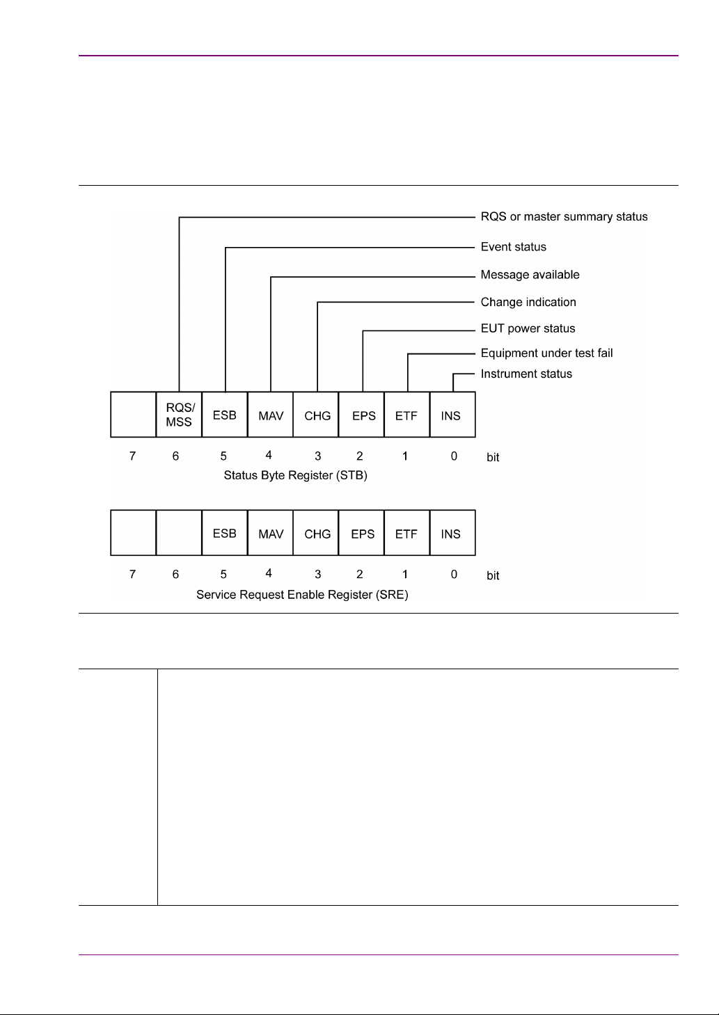
Status Byte Register and Service Request Enable Register
Figure 2-1. Status Byte and Service Request Enable Registers
Table 2- 3 . STB and SRE Bit Definitions
RQS/MSS When the Status byte is read via a Serial Poll operation this bit is RQS (Request
Service). When the Status byte is read via the *STB? Command this bit is MSS
(Master Summary Status). This bit has no function in the Service Request Enable
Register.
(Request service) This bit is set when one of the other bits in the status byte is set
and the corresponding bit in the Service Request Enable Register (SRE) has been
set. When this bit is set an SRQ is indicated over the GPIB interface. The SRQ is
cleared by a serial poll, the status byte returned to the controller and the bit that
caused the SRQ is cleared.
(Master Summary Status) This bit is the inclusive OR of the bitwise combination
(excluding bit 6) of the Status Byte register and the Service Request Enable
register. Note that the *STB? Command does not alter the Status byte, nor will it
clear an SRQ.
2-3
Page 20

GPIB Overview
Tab le 2-4.
ESB (Event status bit) When a bit is set in the event register and the corresponding bit
has been set in the event status enable register (ESE) the ESB bit in the status
register is set.
MAV (Message available) This bit is always set when there is data available to be read
out from the output buffer and it is cleared when the output buffer is empty.
CHG (Change indication) This bit is cleared at power ON initialisation, following a serial
poll, or upon sending the *CLS command. This bit is set when one of the change
bits has been set and the corresponding bit in the change status enable (CHE)
register has been set.
EPS (EUT Power Status) This bit is cleared at power ON initialisation or upon sending
the *CLS command. This bit is set when the EUT power matches the maximum or
minimum power. Use the status command to read whether max or min was
reached.
ETF (Equipment Test Fail) This bit is cleared at power ON initialisation or upon sending
*CLS. This bit is set to indicate a test failure if the following conditions apply: One of
the tests has failed (the instrument will set the appropriate bit in the ETF or EETF
registers) and the appropriate bit within the ETE or EETE registers has been
enabled by the user prior to running the test. See definitions of the ETF, EETF,
ETE, EETE in this manual for more details.
INS (Instrument status) This bit is cleared on initialisation and when the *CLS command
has been sent. This bit is set when one of the instrument status bits has been set
and the corresponding bit in the instrument status enable (INE) register has been
set.
Note
The Status Byte register is read via a Serial Poll or with the *STB? Command. It
cannot be written to directly by the user. The Service Request Enable Register is
written to with the *SRE command and read with the *SRE? Command. It is
cleared by *CLS.
2-4
Page 21
GPIB 488.2 Registers
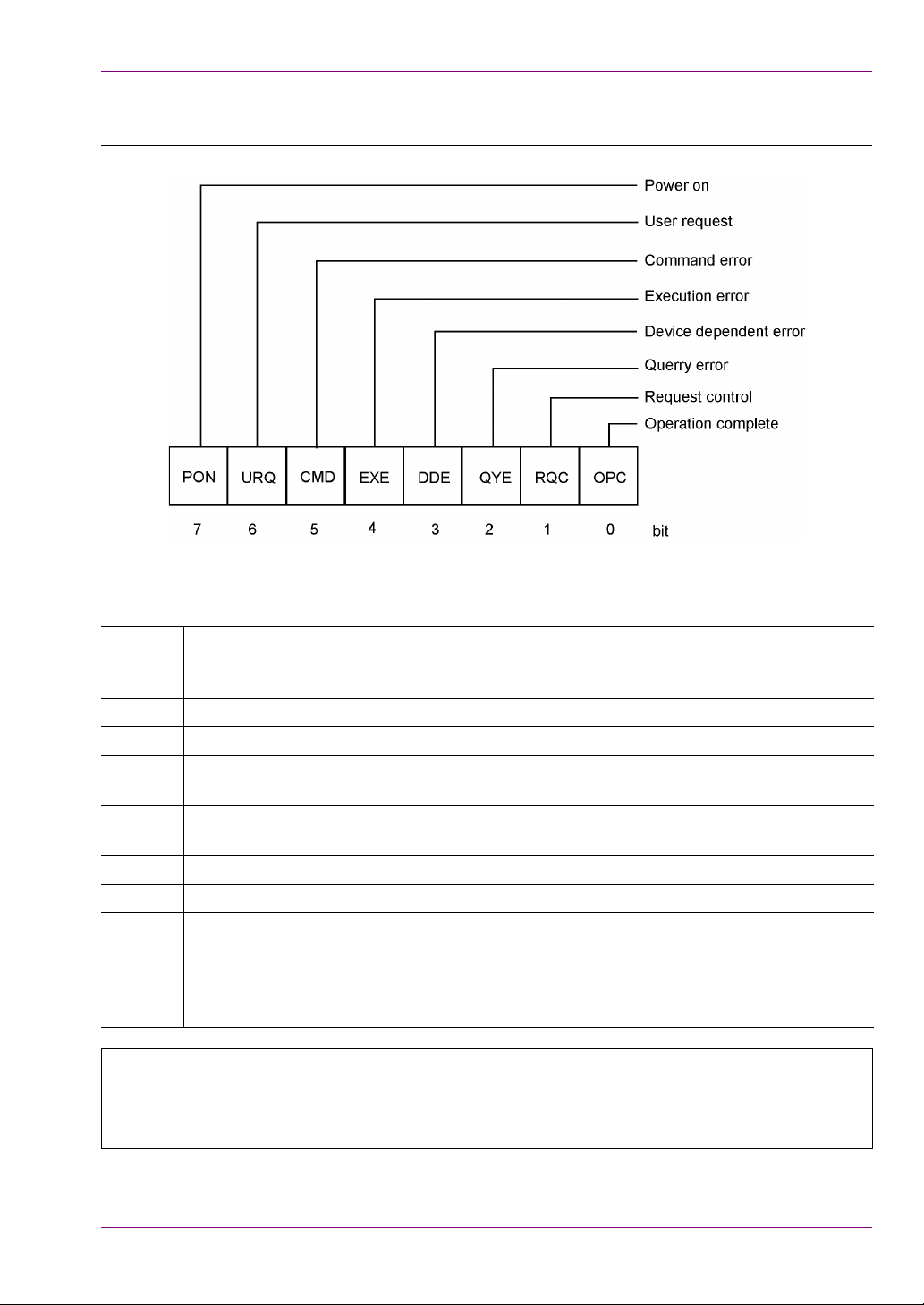
Standard Event Status Register and Standard Event Status Enable Register
Figure 2-2. Standard Event Status and Standard Event Status Enable Registers
Table 2- 5 . ESR and ESE Bit Definitions
PON Power On bit. This bit is set on power up of the device only and cleared if the
instrument is reset or receives a *CLS command. This bit only indicates that a power
on has occurred.
URQ User request
CMD Command error. Received an unrecognized command.
EXE Execution error. Could not execute a command. For example, a parameter is out of
the allowable range.
DDE Device Dependent Error. The specific error can be found by using the ERRLST
command.
QYE Query Error
RQC Request Control. GPIB controllers only.
OPC Operation Complete. When a program message that includes the *OPC command
has been completed and the GPIB interface is idle with any responses read out of the
output buffer this bit is set. For example, if the last command in a configuration
sequence is *OPC, the OPC bit in the event status register is set when that
configuration list has been completed.
The Standard Event Status Register is read with the *ESR? Command. Reading
Note
the ESR clears it. The Standard Events Status Enable Register is written to with
the *ESE command and read with the *ESE? command. Both registers are
cleared by *CLS.
2-5
Page 22

GPIB Overview
EUT Fail Register and Fail Enable Register
Figure 2-3. UET Fail and Fail Enable Registers
This EUT register is cleared on the start of a test or script. When a test completes, if it has
failed the test limit parameters enabled to give a fail result the corresponding bit in this
register is set. These events can be programmed to provide an SRQ by setting the
corresponding bit(s) in the Equipment Under Test Fail Enable Register (ETE).
Tab le 2-6. ETF and ETE Bit Definitions
OP Output power test fail bit. This bit indicates that the output power test failed the limit
criteria set.
PC Power control test fail bit. This bit indicates that the power control test failed the limit
criteria set.
IC Initial carrier test fail bit. This bit indicates that the initial carrier test failed the limit criteria
set.
CD Carrier drift test fail bit. This bit indicates that the carrier drift test failed the limit criteria
set.
MC Modulation index test fail bit. This bit indicates that the modulation index test failed the
limit criteria set.
SS Single slot sensitivity test fail bit. This bit indicates that the single slot sensitivity test
failed the limit criteria set.
MS Multi slot sensitivity test fail bit. This bit indicates that the multi slot sensitivity test failed
the limit criteria set.
MP Maximum input power test fail bit. This bit indicates that the maximum input power
sensitivity test failed the limit criteria set.
Note The EUT Fail register is read with the *ETF?.
2-6
Page 23
GPIB 488.2 Registers
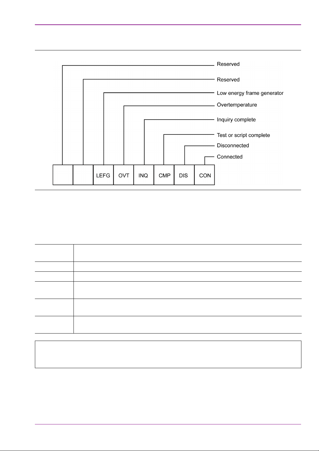
Instrument Status Register and Instrument Status Enable Register
Figure 2-4. Instrument Status and Instrument Status Enable Registers
The INS register displays the present status of the instrument and can be used to provide
SRQs for test or script completion and the connection status of the instrument by setting the
corresponding bits in the INE register.
Table 2- 7 . INS and INE Bit Definitions
LEFG BLE Frame generator counter stopped. This bit is set when the BLE Frame
generator has sent the defined number of packets to the EUT.
OVT Instrument Over temperature Warning.
INQ EUT Address Inquiry complete.
CMP Script or test completion. This bit is cleared when a test or script has started and is
set on its completion or termination.
DIS Disconnect. This bit is cleared when a connection has been made and set when
disconnected.
CON Connection. This bit is set when a connection has been made and cleared when
the connection no longer exists.
A Device Dependant Error (DDE in the ESR register) will indicate if an error
Note
The INS register is read with the *INS? Command. It cannot be cleared by reading it or by
the *CLS command. The INE register is written to by the *INE command and read by the
*INE? Command. It is cleared by *CLS.
occurred, causing the test or script to be aborted. The ERRLST command can be
used to get the cause of the termination.
2-7
Page 24
GPIB Overview
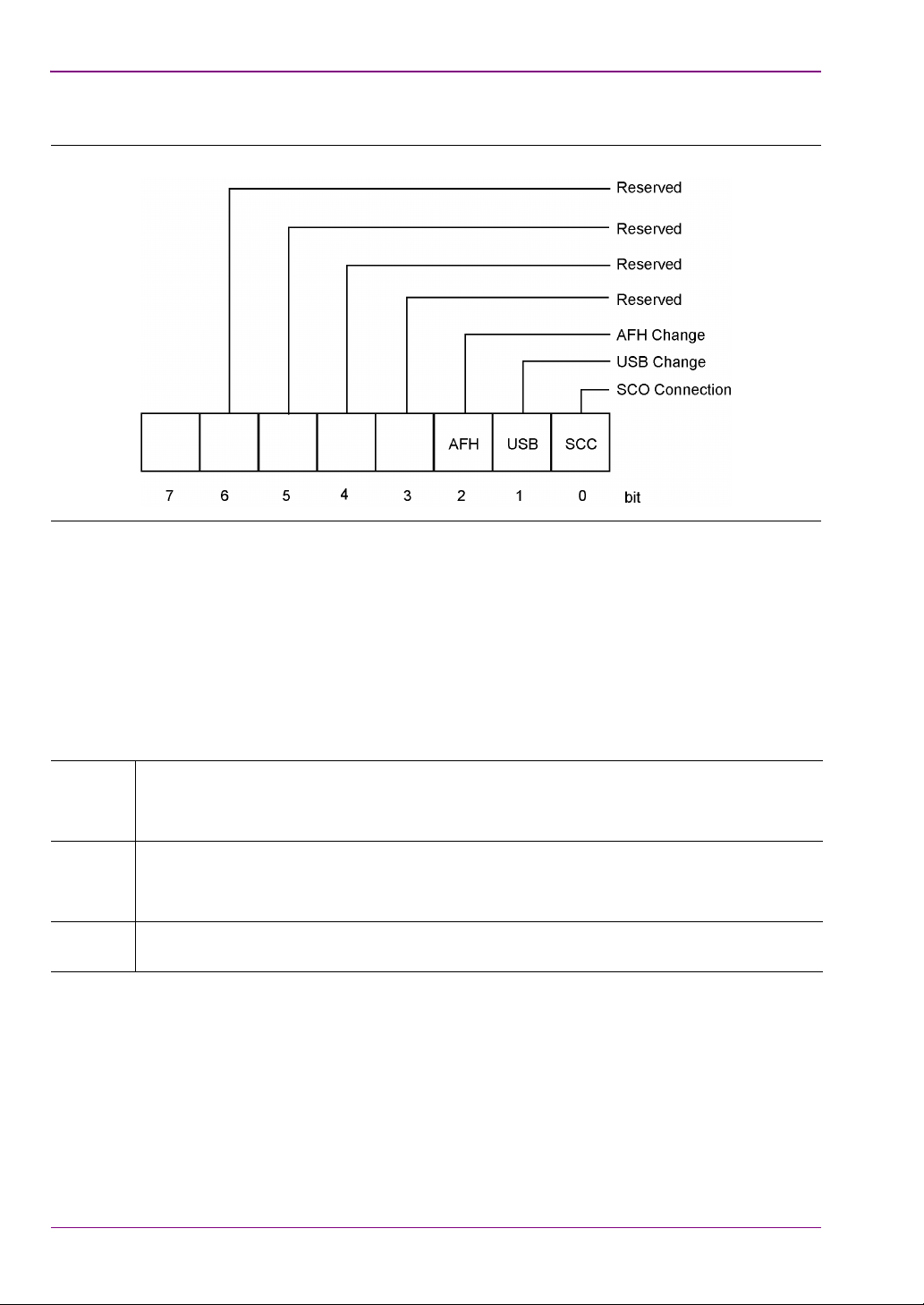
Change Register and Change Enable Register
Figure 2-5. Change and Change Enable Registers
The CHG register indicates when a change of state has occurred in the instrument, and can
be used to provide SRQs by setting the corresponding bits in the CHE register.
The CHG register is read with the *CHG? command. It is cleared by reading it or with the
*CLS command.
The CHE register is written to with the *CHE command and read by the *CHE? command. It
is cleared by the *CLS command.
Tab le 2-8. CHG and CHE Bit Definitions
SCC This bit is set to indicate when a SCO status has changed.
Use the "STATUS" command to retrieve the present SCO status. (MT8852B and
MT8852B-041 only)
USB This bit is set to indicate when a USB attached status has changed.
Use the "STATUS" command to retrieve the present USB status. (MT8852B and
MT8852B-041 only)
AFH This bit is set to indicate that a change has occurred to the channel map. Use
"AFHCFG? ACM" to retrieve the present state of the map.
2-8
Page 25

GPIB 488.2 Registers
EDR EUT Fail Register and EDR EUT Fail Enable Register (MT8852B and
MT8852B-042 only)
Figure 2-6. EDR EUT Fail and EDR EUT Fail Enable Registers
The EDR EETF Test Fail register is cleared at the start of a test or script. If an EDR test
fails any of the test limits applied, the appropriate bit within the EETF register is set (e.g. if
the EDR Sensitivity test fails, the EBS bit is set to '1'). To program the GPIB to provide an
SRQ event upon failure of any of the EDR tests, the appropriate bit(s) must be set within the
EDR EETE Fail Enable register.
Table 2- 9 . EETF and EETE Bit Definitions
EPC Enhanced Power Control test fail bit. This bit indicates whether or not the test failed
the limits criteria set.
EMP EDR Maximum Input Power test fail bit. This bit indicates whether or not the test failed
the limits criteria set.
EFS EDR Floor Sensitivity test fail bit. This bit indicates whether or not the test failed the
limits criteria set.
EBS EDR Sensitivity test fail bit. This bit indicates whether or not the test failed the limits
criteria set.
EDP EDR Differential Phase Encoding test fail bit. This bit indicates whether or not the test
failed the limits criteria set.
ECM EDR Carrier Frequency Stability and Modulation Accuracy fail bit. This bit indicates
whether or not the test failed the limits criteria set.
ERP EDR Relative Transmit Power. This bit indicates whether or not the test failed the
limits criteria set.
Note The EDR EUT Fail register is read with the *EETF? query.
2-9
Page 26
GPIB Overview
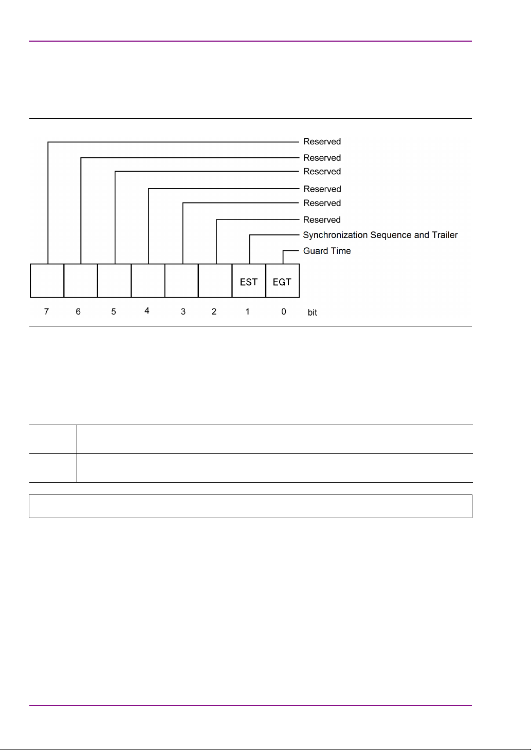
2nd EDR EUT Fail Register and 2nd EDR EUT Fail Enable Register (MT8852B and MT8852B-042 Only)
Figure 2-7. 2
nd
EDR EUT Fail and 2nd EDR EUT Fail Enable Registers
Except the test targets, the 2nd EDR EETF Test Fail register and the 2nd EDR EETE Fail
Enable register are same as the EDR EETF Test Fail register and the EDR EETE Fail
Enable register.
nd
Table 2-10. 2
EETF and 2nd EETE Bit Definitions
EGT EDR Guard Time test fail bit. This bit indicates whether or not the test failed the limits
criteria set.
EST EDR Synchronization Sequence and Trailer test fail bit. This bit indicates whether or
not the test failed the limits criteria set.
Note
The 2
nd
EDR EUT Fail register is read with the *EETF2? Query.
2-10
Page 27
GPIB 488.2 Registers
BLE EUT Fail Register and BLE EUT Fail Enable Register (MT8852B-043
and units with option 27 only)
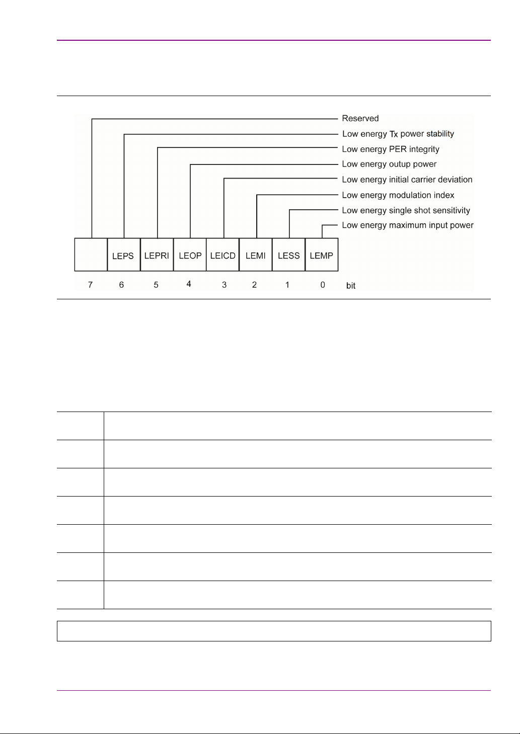
Figure 2-8.
The BLE LEETF Test Fail register is cleared at the start of a test or script. If a BLE test fails
any of the test limits applied, the appropriate bit within the LEETF register is set (e.g., if the
BLE Sensitivity test fails, the LESS bit is set to '1'). To program the GPIB to provide an SRQ
event upon failure of any of the BLE tests, the appropriate bit(s) must be set within the BLE
LEETE Fail Enable register.
Table 2- 11. LEETF and LEETE Bit Definitions
LEPRI PER integrity test fail bit. This bit indicates that the PER integrity test failed the limit
criteria set.
LEOP Output power test fail bit. This bit indicates that the output power test failed the limit
criteria set.
LEICD Initial carrier test fail bit. This bit indicates that the initial carrier test failed the limit
criteria set.
LEMI Modulation index test fail bit. This bit indicates that the modulation index test failed the
limit criteria set
LESS Single slot sensitivity test fail bit. This bit indicates that the single slot sensitivity test
failed the limit criteria set
LEMP Maximum input power test fail bit. This bit indicates that the maximum input power
sensitivity test failed the limit criteria set
LEPS Tx power stability test fail bit. This bit indicates that the Tx power stability test failed
the limit criteria set
Note The EUT Fail register is read with the *LEETF? query.
2-11
Page 28

GPIB Overview
2-6 GPIB over RS232
Version 1.1 or above of the control software supports the use of RS232 in addition to GPIB
commands. Use the RS232 connector on the rear panel of the unit.
Hardware handshake CTS and RTS lines are used to control the flow of data in and out of the
tester and must be available in the cable as hardware handshaking is always enabled. The
RS232 cable used between the COM port on the PC and the connector on the rear of the
MT8852B must be of a Null Modem type such as that supplied with the MT8852B itself.
The DTR and DSR lines are connected together within the tester.
The MT8852B Bluetooth test set’s serial connector pin-outs are:
Table 2-12. Serial Connector Pin Outputs
Pin Signal
1 NOT USED
2Rx Data
3Tx Data
4 DTR handshake signal
5 Signal ground
6 DSR handshake signal
7 RTS handshake signal
8 CTS handshake signal
9 NOT USED
The serial interface baud rate can be set using the MT8852B “System Interfaces” menu under
the menu. Available baud rates are; 1200, 2400, 4800, 9600 (default), 19200, 38400,
57600, and 115200. The other RS232 parameters are predefined as 8 bits, no parity and 1
stop bit and cannot be changed.
Commands are entered in the same manner as the GPIB interface, conforming to the GPIB
command format. All GPIB commands are supported. There are some additional commands,
specific to the serial interface that are prefixed with an exclamation mark (!). All GPIB type
commands and command strings should be terminated with a new line character (0A hex).
The special serial mode commands do NOT require a termination character.
Requested data is returned in the same format as GPIB, but with a preceding 'R' and a
terminating new line character.
SRQs are available, and are output as an SRQ message 'S' followed by a terminating new line
character. When the SRQ message has been received, an "!SPL" command (equivalent to the
GPIB serial poll) can be issued. The tester will respond with the serial poll data message,
which is a single character, proceeded by 'P' and terminated by a new line character.
A device clear message !DCL can be sent to clear the tester input and output message queues,
and terminate any GPIB or serial actions pending.
2-12
Page 29

Summary of RS232 Commands
2-7 Summary of RS232 Commands
Table 2- 1 3 . Mnemonic Definitions
Mnemonic Meaning Comments
!DCL Device clear Clear all queues and
terminates any pending
actions.
!SPL Serial poll Clears SRQ cause and returns
the status byte.
P Response to serial poll Status byte
R Return of requested data
2-13
Page 30

GPIB Overview
2-14
Page 31

Chapter 3 — IEEE 488.2 Mandatory and Register Commands
This chapter provides details of the event register and mandatory commands. The commands
are listed in alphabetical order as shown below.
*CHE (Change Enable Register)
The bits in the Change Enable Register are the same as those in the Change Register. The
two registers are bitwise AND’ed to determine whether to set the CHG bit in the Status
Register.
Set command
format
Remarks <val> is the sum of the binary weights of each of the bits to be enabled.
Example To enable bit 0 (SCO Connection)
Query command
format
Response <val>
Remarks *CHE? Does not clear the Change Enable register. Use *CHE 0 or *CLS
*CHE<ws><val>
<val> decimal representation of an 8 bit binary mask.
See the explanation in chapter 2 for a description of the bits in the
Change and Change Enable registers.
*CHE 1
*CHE?
<val> is a decimal representation of the 8 bit mask as defined above.
for this purpose.
*CHG (Change Register)
Returns the current state of the Change Register (CHG).
Query command
format
Response <val>
Example A return value of 1 indicates that bit 0 (SCO Connection) is set.
Remarks See the explanation in chapter 3 for bit definitions of the Change
*CHG?
<val> is a decimal representation of the binary value of the Change
Register.
Register. *CHG? Does not clear the Change Register.
3-1
Page 32

IEEE 488.2 Mandatory and Register Commands
*CLS (Clear GPIB Status Bytes)
Set command
format
Remarks Clears all the GPIB status data structures, including the Event Status
*CLS
Register and Status Register, except for the MAV bit. *CLS does not
clear the Output Queue.
*EETE (EDR EUT Fail Enable Register) (MT8852B and MT8852B-042 only)
The bits in the EDR EUT Fail Enable Register are the same as those in the EDR EUT Fail
Register. The two registers are bitwise AND’ed to determine which failed test(s) will generate
a SRQ event.
Set command
format
Remarks <val> is the sum of the binary weights of each of the bits to be enabled.
Examples To enable bit 3 (EDR Sensitivity)
*EETE<ws><val>
<val> decimal representation of an 8 bit binary mask.
Refer to chapter 3 of this manual for a description of the bits in the EDR
EUT Fail and EDR EUT Fail Enable registers.
*EETE 8
To enable bit 5 (EDR Maximum Input Power)
*EETE 32
To enable both bits
*EETE 40
Query command
format
Response <val>
Remarks *EETE? Does not clear the EUT Fail Enable register. Use *EETE 0 or
3-2
*EETE?
<val> decimal representation of an 8 bit binary mask.
<val> is a decimal representation of the 8 bit mask as defined above.
*CLS for this purpose.
Page 33

*EETE2 (2nd EDR EUT Fail Enable Register)
*EETE2 (2nd EDR EUT Fail Enable Register) (MT8852B and MT8852B-042
only)
The bits in the 2nd EDR EUT Fail Enable Register are the same as those in the 2nd EDR EUT
Fail Register. The two registers are bitwise AND’ed to determine which failed test(s) will
generate a SRQ event.
Set command
format
Remarks <val> is the sum of the binary weights of each of the bits to be enabled.
Examples To enable bit 0 (Guard Time)
Query command
format
Response <val>
Remarks *EETE2? Does not clear the EUT Fail Enable register. Use *EETE2 0 or
*EETE2<ws><val>
<val> decimal representation of an 8 bit binary mask.
Refer to chapter 3 of this manual for a description of the bits in the EDR
EUT Fail and 2
*EETE2 1
To enable bit 1 (Synchronization Sequence and Trailer)
*EETE2 2
To enable both bits
*EETE2 3
*EETE2?
<val> decimal representation of an 8 bit binary mask.
<val> is a decimal representation of the 8 bit mask as defined above.
*CLS for this purpose.
nd
EDR EUT Fail Enable registers.
3-3
Page 34

IEEE 488.2 Mandatory and Register Commands
*EETF (EDR EUT Fail Register Query) (MT8852B and MT8852B-042 only)
Returns the current state of the EDR EUT Fail Register (EETF).
Query command
*EETF?
format
Response <val>
<val> is a decimal representation of the binary value of the EDR EUT
Fail Register.
Example A return value of 9 indicates that bit 0 (EDR Relative Transmit Power)
and bit 3 (EDR Sensitivity) are set.
Remarks See chapter 2 for bit definitions of the EDR EUT Fail Register.
*EETF? Clears the EDR EUT Fail Register.
*EETF2 (2nd EDR EUT Fail Register Query) (MT8852B and MT8852B-042
only)
Returns the current state of the 2nd EDR EUT Fail Register (EETF2).
Query command
format
Response <val>
Example A return value of 3 indicates that bit 0 (Guard Time) and bit 1
Remarks
*EETF2?
<val> is a decimal representation of the binary value of the 2
EUT Fail Register.
(Synchronization Sequence and Trailer) are set.
See chapter 2 for bit definitions of the 2
*EETF2? Clears the 2
nd
EDR EUT Fail Register.
nd
EDR EUT Fail Register.
nd
EDR
3-4
Page 35

*ESE (Standard Event Status Enable)
*ESE (Standard Event Status Enable)
The bits in the Standard Event Status Enable Register are the same as those in the Standard
Event Status Register. The two registers are bitwise AND’ed to determine which standard
event(s) will generate a SRQ.
Set command
format
Remarks <val> is the sum of the binary weights of each of the bits to be enabled.
Examples:- To enable bit 4 (Execution Error)
Query command
format
Response <val>
Remarks *ESE? Does not clear the Standard Event Status Enable register. Use
*ESE<ws><val>
<val> decimal representation of an 8 bit binary mask.
Refer to chapter 3 of this manual for a description of the bits in the
Standard Event Status and Standard Event Status Enable registers.
*ESE 16
To enable bit 5 (Command Error)
*ESE 32
To enable both bits
*ESE 48
*ESE?
<val> is a decimal representation of the 8 bit mask as defined above.
*ESE 0 or *CLS for this purpose.
3-5
Page 36

IEEE 488.2 Mandatory and Register Commands
*ESR (Standard Event Status Register Query)
Returns the current state of the Standard Event Register (ESR).
Query command
format
Response <val>
Example A return value of 5 indicates that bits 0 (Operation Complete) and 2
Remarks See chapter 2 for bit definitions of the Standard Event Status Register.
*ESR?
<val> is a decimal representation of the binary value of the Standard
Event Status Register.
(Query Error) are set.
*ESR? Clears the Standard Event Status Register.
*ETE (EUT Fail Enable Register)
The bits in the EUT Fail Enable Register are the same as those in the EUT Fail Register. The
two registers are bitwise AND’ed to determine which failed test(s) will generate a SRQ.
Set command
format
Remarks <val> is the sum of the binary weights of each of the bits to be enabled.
Examples To enable bit 4 (Carrier Drift)
*ETE<ws><val>
<val> decimal representation of an 8 bit binary mask
Refer to chapter 3 of this manual for a description of the bits in the EUT
Fail and EUT Fail Enable registers.
*ETE 16
To enable bit 5 (Initial Carrier)
*ETE 32
To enable both bits
*ETE 48
Query command
format
Response <val>
Remarks *ETE? Does not clear the EUT Fail Enable register. Use *ETE 0 or
3-6
*ETE?
<val>decimal representation of an 8 bit binary mask
<val> is a decimal representation of the 8 bit mask as defined above.
*CLS for this purpose.
Page 37

*ETF (EUT Fail Register Query)
Returns the current state of the EUT Fail Register (ETF).
*IDN (Identification Query)
Query command
format
Response <val>
Example A return value of 5 indicates that bits 0 (Maximum Input Power) and 2
Remarks See chapter 2 for bit definitions of the EUT Fail Register. *ETF? Clears
*ETF?
<val> is a decimal representation of the binary value of the EUT Fail
Register.
(Single Slot Sensitivity) are set.
the EUT Fail Register.
*IDN (Identification Query)
Query command
format
Response A string is returned containing the manufacturer’s name, the model
Example ANRITSU,MT8852B,00801001,4.16.000
Remarks The operation of this command is identical to SYSCFG? IDENT see
*IDN?
(alternatively OI can be used)
number, the serial number, and the software revision. Commas
separate the items.
chapter 5 for details.
3-7
Page 38

IEEE 488.2 Mandatory and Register Commands
*INE (Instrument Status Enable Register)
The bits in the Instrument Status Enable Register are the same as those in the Instrument
Status Register. The two registers are bitwise AND’ed to determine which condition(s) will
generate a SRQ.
Set command
format
Remarks <val> is the sum of the binary weights of each of the bits to be enabled.
Example To enable bit 3 (Inquiry Complete)
Query command
format
Response <val>
Remarks *INE? Does not clear the Instrument Status Enable register. Use *INE
*INE<ws><val>
<val> decimal representation of an 8 bit binary mask.
Refer to chapter 2 of this manual for a description of the bits in the
Instrument Status and Instrument Status Enable registers.
*INE 8
To enable bit 2 (Test or Script Complete)
*INE 4
To enable both bits
*INE 12
*INE?
<val> is a decimal representation of the 8 bit mask as defined above.
0 or *CLS for this purpose.
*INS (Instrument Status Register Query)
Returns the current state of the Instrument Status Register (INS).
Query command
format
Response <val>
Example A return value of 5 indicates that bits 0 (Connected) and 2 (Test or
Remarks See chapter 2 for bit definitions of the Instrument Status Register.
3-8
*INS?
<val> is a decimal representation of the binary value of the Instrument
Status Register.
Script Complete) are set.
*INS? Does not clear the Instrument Status Register.
Page 39

*LEETF (BLE EUT Fail Register Query)
*LEETE (BLE EUT Fail Enable Register) (Option 27 and MT8852B-043 only)
The bits in the BLE EUT Fail Enable Register are the same as those in the BLE EUT Fail
Register. The two registers are bitwise AND'ed to determine which failed test(s) will generate
a SRQ event.
Set command
format
Remarks <val> is the sum of the binary weights of each of the bits to be enabled.
Examples To enable bit 2 (BLE Modulation index)
Query command
format
Response <val>
Remarks *LEETE? Does not clear the EUT Fail Enable register. Use *LEETE 0
*LEETE<ws><val>
<val> decimal representation of an 8 bit binary mask.
Refer to chapter 2 of this manual for a description of the bits in the BLE
EUT Fail and BLE EUT Fail Enable registers.
*LEETE 4
To enable bit 0 (BLE Maximum Input Power)
*LEETE 1
To enable both bits
*LEETE 5
LEETE?
<val> decimal representation of an 8 bit binary mask
<val> is a decimal representation of the 8 bit mask as defined above.
or *CLS for this purpose.
*LEETF (BLE EUT Fail Register Query) (Option 27 and MT8852B-043 only)
Returns the current state of the BLE EUT Fail Register (LEETF).
Command format *LEETF?
Response <val>
<val> is a decimal representation of the binary value of the BLE EUT
Fail Register.
Example A return value of 5 indicates that bit 0 (BLE Modulation Index) and bit
2 (BLE Maximum Input Sensitivity) are set.
Remarks See chapter 2 for bit definitions of the BLE EUT Fail Register.
*LEETF? Clears the BLE EUT Fail Register.
3-9
Page 40

IEEE 488.2 Mandatory and Register Commands
*OPC (Operation Completed Indication)
These commands generate indications when all pending operations are completed. An
operation is complete when all input messages processed and all responses have been written
into the GPIB Output queue.
Set command
format
Example OPMD SCRIPT;SCPTSEL 3; *OPC
Remarks The OPC bit is set in the ESR when the OPMD and SCPTSEL
Query command
format
Example OPMD SCRIPT;SCPTSEL 3; *OPC?
Remarks An ASCII ‘1’ is placed in the Output queue when the OPMD and
*OPC
commands have been completed.
*OPC?
SCPTSEL commands have been completed.
*RST (Instrument Reset)
Resets the MT8852B to its default state.
Set command
format
Remarks The GPIB Address is not changed and the GPIB Status registers and
*RST
Input/Output queues are not cleared. The effect of this command is the
same as pressing the PRESET key on the front panel.
3-10
Page 41

*STB (Status Byte Register Query)
*SRE (Service Request Enable Register)
The bits in the Service Request Enable Register (SRE) are the same as those in the Status
Byte Register (STB) except for bit 6, which is not used in the SRE. With the exception of bit 6
the two registers are bitwise AND’ed to determine which condition(s) will generate a SRQ.
Set command
format
Remarks <val> is the sum of the binary weights of each of the bits to be enabled.
Examples To enable bit 4 (Message Available)
Query command
format
Response <val>
Remarks *SRE? Does not clear the Instrument Status Enable register. Use *SRE
*SRE<ws><val>
<val> decimal representation of an 8 bit binary mask.
Refer to chapter 2 of this manual for a description of the bits in the
Status Byte and Service Request Enable registers. Note that bit 6
should never be set.
*SRE 16
To enable bit 2 (Internal Error)
*SRE 4
To enable both bits
*SRE 20
*SRE?
<val> is a decimal representation of the 8 bit mask as defined above.
0 or *CLS for this purpose. Bit 6 will never be set.
*STB (Status Byte Register Query)
Returns the current state of the Status Byte Register (STB) with the RQS bit replaced by the
MSS bit (bit 6).
Query command
format
Response <val>
Example A return value of 70 indicates that bits 1 (EUT Fail), 2 (Internal Error
Remarks See chapter 2 for bit definitions of the Status Byte Register. *STB? Does
3-11
*STB?
<val> is a decimal representation of the binary value of the Instrument
Status Register.
Bit), and bit 6 (Master Summary Status) are set.
not clear the Instrument Status Register.
Page 42

IEEE 488.2 Mandatory and Register Commands
*TST (Self Test Query)
Invokes an instrument Self-Test cycle and places the results in the Output Queue
Query command
format
Response “ALL TESTS PASSED”
Remarks This command differs from STERR in that it invokes a Self-Test before
*TST?
“SELFTEST FAILED”
returning the results.
*WAI (Wait to Continue)
This mandatory IEE488.2 command is decoded but produces no action because the
Overlapping Commands feature is not implemented on the MT8852B.
Set command
format
*WAI
3-12
Page 43

Chapter 4 — General GPIB Commands
BOOTSTATUS? (Startup Self Test Status Request )
Query Command
format
Remarks On startup the instrument performs a self test. If the self test fails, a
Related
Commands
BOOTSTATUS?
warning screen is displayed indicating the cause. This command
returns the status of the instrument during power up.
0 Passed self test. Instrument running.
1 Startup running self test.
–1 Self test FAILED.
During the startup procedure all commands except STERR,
BOOTSTATUS?, CONT and GPIB 488.2 event and status commands
will produce a GPIB execution error. STERR will return the self test
results.
STERR, CONT
CONT (Continue After Self Test)
Set command
format
Remarks This command will allow the system to continue the startup sequence if
Related
Commands
CONT
there are self test failures other than DSP errors.
STERR, BOOTSTATUS?
4-1
Page 44

General GPIB Commands
ERRLST (Error List)
This command reads out and clears the recorded error states latch. The error states latch
records an error occurring and retains the error states until the instrument is reset, the
power is cycled, or the error states latch is read using this command. The errors are indicated
via the DDE bit of the event register (ESR).
Set command
format
Response ABCCDDEFGHIIJKK!LLLLLLL!MMMMMMM!NNNNNNN!OOOOOO
A CONNECTION ALREADY
EXISTS
B EUT TEST MODE STATE 0 EUT Test Mode enabled
CC EUT HCI ERROR 00 OK
DD INTERNAL HCI ERROR 00 OK
E INTERNAL SYNC ERROR 0 OK
F EUT SYNC ERROR 0 OK
G EUT HARDWARE ERROR 0 OK
H REQUEST FAILED 0 OK
II DSP STATUS 00 OK
ERRLST
O!
0
1
1 EUT Test Mode not enabled
XX 2 digit hexadecimal error code (EUT
XX 2 digit hexadecimal error code
1 Internal HCI synchronization error
1 EUT HCI synchronization error (control
1 EUT Reported HCI Hardware error
1 Request failed (system busy)
01 Searching channel
02 Searching sync word
03 Incorrect packet length
04 No payload
05 Auto ranging
06 Incorrect packet
07 Incorrect packet type
08 Over range
09 Under range
No previous connection
Connection already exists
controlled via RS232 interface)
via RS232)
message
4-2
Page 45

CONT (Continue After Self Test)
10 Invalid payload
11 Error finding start of packet using power
profile
12 Error locating P0/GFSK sync word
13 Location of P0/GFSK sync word exceeds
allowed limits
14 Error locating EDR sync word
15 Location of EDR sync word exceeds
allowed limits
16 Error decoding the packet type field
17 Modulation mode of PI/4-DQPSK or
8DPSK not specified
18 Specified (pi/4-DQPSK) modulation mode
does not agree with detected packet type
19 Specified (8DPSK) modulation mode does
not agree with detected packet type
20 Invalid packet type decoded
21 Unknown packet type decoded
22 Expected and measured packet lengths do
not match
23 Insufficient blocks in packet for
measurement
Note Setting of the DSP status code will not set the DDE bit of the event register.
J EUT BT ADDRESS 0 OK
1 No EUT Bluetooth Address set (in Manual
mode)
KK HCI COMM STATUS 00 OK
01 Unknown HCI command
02 No connection
03 Hardware failure
04 Paging timeout
05 Connection timeout
06 Unsupported feature parameter
07 Connection ended by user
08 Low resource connection ended
09 Power Off connection ended
10 Local host connection ended
11 Unsupported remote feature
4-3
Page 46

General GPIB Commands
12 Role change not allowed
13 LMP response timeout
14 IQ modem DAC saturation
LLLLLLL Internal core error text (variable length)
MMMMMMM EUT core error text (variable length)
NNNNNNN Last GPIB command that caused a Command error (variable length)
OOOOOOO Last GPIB command that caused a Execution error (variable length)
EUTINIT (Bluetooth Peripheral Mode)
This command puts the MT8852B into Bluetooth Peripheral mode. It is the equivalent to:
.> “System Features” > “Connection Control” > “Make me an EUT”.
Set command
format
Remarks To return the MT8852B to normal (Central) mode, use *RST.
EUTINIT
EUTMAXPWR (Send EUT to Max Power Control)
This command enables or disables the setting of an EUT to maximum power at the start of a
test even if the EUT reports that it supports power control.
Set command
format
Example Example to set to OFF
Query command
format
Response If script 4 was OFF then response would be:
EUTMAXPWR<ws><script><,><state>
<script> 1 to 10
<state> ON or OFF
EUTMAXPWR 3,OFF
EUTMAXPWR?<ws><script>
EUTMAXPWR 4,OFF
LECTETIME (Set the CTE time)
This command sets the CTE time for Bluetooth low energy (BLE) tests with CTE.
Set command
format
Example To set the CTE time to 20, the command would be:
4-4
LECTETIME<ws><script number><,><value>
<script number> 3 to 10
<value> 2 to 20 (Default 2)
LECTETIME 3,20
Page 47

LECTETIMEMODE (Set the CTE time mode)
Query command
format
Response The response is the CTE time.
Example To request the CTE time for BLE tests in script 7, the command would
Response If the CTE time has previously been set to 18
LECTETIME?<ws><script number>
<script number> 1 to 10
be:
LECTETIME? 7
LECTETIME 7,18
LECTETIMEMODE (Set the CTE time mode)
This command sets the CTE time mode for Bluetooth low energy (BLE) tests with CTE.
Set command
format
Example To set the CTE time mode to AUTO, the command would be:
Remarks AUTO - In this mode the MT8852B will request the CTE time from the
LECTETIMEMODE<ws><script number><,><value>
<script number> 3 to 10
<value> AUTO (Default) or MANUAL
LECTETIMEMODE 3,AUTO
EUT.
If the EUT address source is BLE2WIRE/USBBLE2WIRE or if the EUT
responds to the HCI command with an error, the CTE time
(LECTETIME) will be set to the default value, 20.
MANUAL - In this mode the CTE time can be set between 2 and 20
using LECTETIME.
Query command
format
Response The response is the CTE time mode.
Example To request the CTE time mode for BLE tests in script 7, the command
Response If the mode has previously been set to MAUAL
LECTETIMEMODE?<ws><script number>
<script number> 1 to 10
would be:
LECTETIMEMODE? 7
LECTETIMEMODE 7,MANUAL
4-5
Page 48

General GPIB Commands
LEPKTLEN (Set the BLE data packet length)
This command sets the data packet length for Bluetooth low energy (BLE) tests.
Set command
format
Example To set the packet length to 45 bytes, the command would be:
Query command
format
Response The response is the packet length.
Example To request the packet length for BLE tests in script 5, the command
Response If the length has previously been set to 45
LEPKTLEN<ws><script number><,><packet length>
<script number> 1 to 10
<packet length> 2 to 255 bytes (Default 37)
LEPKTLEN 1,45
LEPKTLEN?<ws><script number>
<script number> 1 to 10
would be:
LEPKTLEN? 5
LEPTKLEN 5,45
LEPKTMODE (Set the BLE data packet mode)
This command sets the data mode for the Bluetooth low energy (BLE) tests.
Set command
format
Example To set the packet mode to AUTO, the command would be:
Remarks AUTO - In this mode the MT8852B will request the maximum data
LEPKTMODE<ws><script number><,><mode>
<script number> 1 to 10
<mode> AUTO or MANUAL (default)
LEPKTMODE 1,AUTO
length from the EUT.
If the EUT address source is BLE2WIRE/USBBLE2WIRE or if the EUT
responds to the HCL command with an error, the data length will be set
to the default value, 37.
MANUAL - In this mode the data length can be set between 2 and 255
bytes using LEPKTLEN.
Query command
format
Example To request the packet mode for BLE tests in script 5, the command
4-6
LEPKTMODE?<ws><script number>
<script number> 1 to 10
would be:
LEPKTMODE? 5
Page 49

LKPASS (Update Lock/Unlock Password)
Response If the mode had previously been set to AUTO
LEPKTMODE 5,AUTO
LKPASS (Update Lock/Unlock Password)
This command enables the operator to change the script lock password. The password is a
number between 1 and 65535. All spaces are removed.
Set command
format
Example To change the present password “1234” to “6543”, the command would
LKPASS<ws><old password><,><new password>
<old password> Present lock/unlock password
<new password> New lock/unlock password
be:
LKPASS 1234,6543
LOCK (Script Lock)
This command locks a script so that it cannot be altered unless it is unlocked with the unlock
command. The enquiry version of this command will return TRUE or FALSE indicating
whether a script has been locked.
Set command
format
Example Lock script 4
Query command
format
Response The response is just a TRUE or FALSE.
Example To request the status of script 5 the command would be:
Response If script 5 is locked
LOCK<ws><script number><,><password>
<script number> 3 to 9
<password> The lock/unlock password. Default is “1234”.
LOCK 4,1234
LOCK?<ws><script number>
<script number> 1 to 9
LOCK? 5
TRUE
4-7
Page 50

General GPIB Commands
OPMD (Operation Mode)
This command configures the operation mode of the instrument.
Set command
format
OPMD<ws><operation mode>{<,><test>}
<operation mode>
SCRIPT script mode
STEST single test mode
SIGGEN signal generator mode
ESIGGEN EDR signal generator mode
LESIGGEN BLE signal generator mode
CWMEAS CW measurement mode
ECWMEAS EDR CW measurement mode
Selected script test <test>
OP Output power
PC Power control
EPC Enhanced power control
MI Modulation Index
IC Initial carrier
CD Carrier drift
SS Single slot sensitivity
MS Multi slot sensitivity
MP Max input power
ERP EDR Relative transmit power test
(MT8852B and MT8852B-042 only)
ECM EDR Carrier frequency stability and
modulation accuracy test (MT8852B and
MT8852B-042 only)
EDP EDR Differential phase encoding test
(MT8852B and MT8852B-042 only)
EBS EDR Sensitivity test
(MT8852B and MT8852B-042 only)
EFS EDR Floor sensitivity test
(MT8852B and MT8852B-042 only)
EMP EDR Maximum Input Power test
(MT8852B and MT8852B-042 only)
EGT EDR Guard Time
(MT8852B and MT8852B-042 only)
EST EDR Synchronization Sequence and Trailer
(MT8852B and MT8852B-042 only)
4-8
Page 51

LOCK (Script Lock)
LEOP BLE Output power
(option 27 and MT8852B-043 only)
LEICD BLE Carrier frequency offset and drift
(option 27 and MT8852B-043 only)
LEMI BLE Modulation characteristics
(option 27 and MT8852B-043 only)
LESS BLE Receiver sensitivity
(option 27 and MT8852B-043 only)
LEPRI BLE PER report integrity test
(option 27 and MT8852B-043 only)
LEMP BLE Max input signal level
(option 27 and MT8852B-043 only)
LEPS BLE Tx power stability
(option 37 only)
Remarks <test> is applicable only when the operation mode is set to STEST.
Changing from SIGGEN, ESIGGEN, or LESIGGEN modes to any of the
other modes will cause a reset of the internal Bluetooth core.
Note that in single test mode, only the test that has been selected can be
configured. An execution error is returned if an attempt is made to
configure any other tests.
Example 1 Set to script mode.
OPMD SCRIPT
Example 2 Set to single test mode, with the initial carrier test selected
OPMD STEST,IC
Example 3 Set to single test mode, with the EDR differential phase encoding test
selected.
OPMD STEST,EDP
Query command
OPMD?
format
Response Response is in the form of the command to set that state.
Example If the operation mode is single test mode with the power control test
selected the command would be:
OPMD?
Response OPMD STEST,PC
4-9
Page 52

General GPIB Commands
OPTSTATUS? (Option Status)
Query command
format
Remarks This command returns the options enabled.
Response OPTSTATUS,<num_opts>{,<options>,...}
Example If option 15 is the only option enabled the response would be.
Response OPTSTATUS,1,15
OPTSTATUS?
<num_opts> 0 to 7 (five options available at present)
Number of enabled options that follow.
<options> Comma separated list of enabled options
15 AFH (Adaptive frequency hopping) support
17 Allows IQ data output for EDR measurements
25 EDR Measurements support
27 BLE Measurements support
29 BLE Measurements only
34 BLE Data Length Extension support
35 BLE 2LE support
36 BLE BLR support
37 BLE AoA/AoD support
70 Platform Enhanced option
SCPTCFG (Configure Script)
This command is used to select which tests are run as part of a script. All scripts and their
tests are independent.
Set command
format
4-10
SCPTCFG<ws><script number><,><test><,><state>
<script number> 3 to 10
<test>
OP Output power
PC Power control
MI Modulation Index
IC Initial carrier
CD Carrier drift
SS Single slot sensitivity
MS Multi slot sensitivity
MP Max input power
ERP EDR Relative transmit power test (MT8852B
and MT8852B-042 only).
Page 53

SCPTCFG (Configure Script)
ECM EDR Carrier frequency stability and
modulation accuracy test (MT8852B and
MT8852B-042 only).
EDP EDR Differential phase encoding test
(MT8852B and MT8852B-042 only)
EBS EDR Sensitivity test (MT8852B and MT8852B-
042 only)
EFS EDR floor sensitivity test (MT8852B and
MT8852B-042 only)
EMP EDR Maximum Input Power test (MT8852B
and MT8852B-042 only)
EGT EDR Guard Time
(MT8852B and MT8852B-042 only)
EST EDR Synchronization Sequence and Trailer
(MT8852B and MT8852B-042 only)
EPC Enhanced power control
LEOP BLE Output power
(option 27 and MT8852B-043 only)
LEMI BLE Modulation index
(option 27 and MT8852B-043 only)
LEICD BLE Initial carrier
(option 27 and MT8852B-043 only)
LESS BLE Single shot sensitivity
(option 27 and MT8852B-043 only)
LEMP BLE Max input power
(option 27 and MT8852B-043 only)
LEPRI BLE Max input power
(option 27 and MT8852B-043 only)
LEPS BLE Tx power stability
(option 37 only)
STDTSTS To set the status of all the basic rate tests in
this script at once. (MT8852B and MT8852B042 only)
EDRTSTS To set the status of all the EDR tests in this
script at once. (MT8852B and MT8852B-042
only)
BLETSTS To set the status of all the BLE tests in this
script at once. (option 27 and MT8852B-043
only)
PCTSTS Turns on or off both power control tests when
the EPC option is installed.
ALLTSTS To set the status of all tests in this script at
once
4-11
Page 54

General GPIB Commands
<state> ON | OFF
Remarks All ten scripts can be read but only 3 to 10 can be set.
Example To select the output power test in script 4 the command would be:
SCPTCFG 4,OP,ON
4-12
Page 55

SCPTCFG (Configure Script)
Query command
format
SCPTCFG?<ws><script number>[,<ext-code>]
<script number> 1 to 10
<ext-code>
0 or omitted : standard (except EGT, EST, and LEPS)
1 : with EGT and EST (except LEPS)
2 : with EGT and EST and LEPS
Response The response is a list of ON or OFF for each test in the following order
separated by commas.
• Output power
• Power control
• Modulation Index
• Initial carrier
• Carrier drift
• Single slot sensitivity
• Multi slot sensitivity
• Max input power
• EDR Relative Transmit Power test (MT8852B and MT8852B-
042 only)
• EDR Carrier Frequency stability and Modulation accuracy test
(MT8852B and MT8852B-042 only)
• EDR Differential Phase Encoding test (MT8852B and
MT8852B-042 only)
• EDR Sensitivity test (MT8852B and MT8852B-042 only)
• EDR BER Floor Sensitivity test (MT8852B and MT8852B-042
only)
• EDR Maximum Input Power test (MT8852B and MT8852B-042
only)
• EDR Guard Time (MT8852B and MT8852B-042 only)
• EDR Synchronization Sequence and Trailer (MT8852B and
MT8852B-042 only)
• Enhanced power control
• BLE Output power (option 27 or MT8852B-043 only)
• BLE Modulation Index (option 27 or MT8852B-043 only)
• BLE Carrier and drift (option 27 or MT8852B-043 only)
• BLE sensitivity (option 27 or MT8852B-043 only)
• BLE Max input power (option 27 or MT8852B-043 only)
• BLE PER integrity (option 27 or MT8852B-043 only)
• BLE TX power stability (option 37 only)
4-13
Page 56

General GPIB Commands
Example To read the configuration of script 5 where all tests are selected except
power control and the BLE tests, the command would be:
SCPTCFG? 5
Response ON,OFF,ON,ON,ON,ON,ON,ON,ON,ON,ON,ON,ON,ON,ON,
OFF,OFF,OFF,OFF,OFF,OFF
Example To read the configuration of script 4 where all tests are selected
except power control and the BLE tests with extension code '1', the
command would be:
SCPTCFG? 4,1
Response ON,OFF,ON,ON,ON,ON,ON,ON,ON,ON,ON,ON,ON,ON,ON,ON,ON,O
FF,OFF,OFF,OFF,OFF,OFF
SCPTNM (Set Script Name)
Set or request the script name. The Anritsu predefined scripts names cannot be set.
Set command
format
SCPTNM<ws><script number><,><script name>
<script number> 3 to 10
<script name> Script name using up to 9 characters.
Remarks
If more than 9 characters are used the name is terminated at the 9
character. The names of scripts 1 and 2 cannot be modified. If the script
number is set to 1 or 2 an execution error is output.
Example To set the name of script 4 to “ENG TEST1” the command would be:
SCPTNM 4,ENG TEST1
Query command
format
SCPTNM?<ws><script number>
<script number> 1 to 10
All ten scripts can be read but only 3 to 10 can be set.
Response Response is in the form of the command to set that state.
Example If the script 5 name is “ENG TEST X” the command would be:
SCPTNM? 5
Response SCPTNM 5,ENG TEST X
th
4-14
Page 57

SCPTRST (Reset Script)
This command resets a script to its default values.
SCPTSEL (Select Script)
Set command
format
Remarks ‘ALL’ resets all 10 test scripts at once.
Example 1 Reset script 3.
Example 2 Reset all scripts
SCPTRST<ws><script number>
<script number> 1 to 10 | ‘ALL’
SCPTRST 3
SCPTRST ALL
SCPTSEL (Select Script)
Set or request the selected script to be executed. If this command is sent when in single test
mode, the selected test is executed.
Set command
format
Example SCPTSEL 1
Query command
format
Example If the script selected was 5 the response would be:
Response SCPTSEL 5
SCPTSEL<ws><script number>
<script number> 1 to 10
SCPTSEL?
Response is in the form of the command to set that state.
SCPTTSTGP (Set Test Group State) (MT8852B and MT8852B-042 only)
This command is used to select which groups of tests are run as part of a script. The states of
all the tests in the selected group are affected by this command, e.g., turning off a group will
turn off all tests within that group.
Set command
format
SCPTTSTGP<ws><script number><,><testgroup><,> <state>
<test group>
STDTSTS To set the status of all the basic rate tests in this script at
once.
EDRTSTS To set the status of all the EDR tests in this script at
once.
BLETSTS To set the status of all the BLE tests in this script at
once.
ALLTSTS To set the status of all tests in this script at once.
<state> ON | OFF
4-15
Page 58

General GPIB Commands
Example To select the standard tests in script 4 the command would be:
SCPTTSTGP 4,STDTSTS,ON
Query command
format
Response The response is a list of ON or OFF for each test group (Basic rate, EDR,
Example To read the configuration of script 5 where basic rate tests are selected
Response SCPTTSTGP 5,ON,OFF,OFF
This command outputs the test group states of this script.
SCPTTSTGP?<ws><script number>
<script number> 1 to 10
and low energy tests) separated by commas.
but the EDR and BLE tests are not:
SCPTTSTGP? 5
SCRIPTMODE (Script Mode)
This command determines how the tests within the specified script are run.
Set command
format
Example Set the Script Mode for script 3 to NULL Packet
Query command
format
Response The response is in the form of the command to set that state.
Example If the script mode for script 9 is set to standard the command would be:
SCRIPTMODE<ws><script number><,><mode>
<script number> 3 to 10
<mode>
STANDARD
NULLPKT
SINGLEPAYLOAD
SCRIPTMODE 3,NULLPKT
SCRIPTMODE?<ws><script number>
<script number> 1 to 10
SCRIPTMODE? 9
Will produce the response:
SCRIPTMODE 9,STANDARD
4-16
Page 59

SCRIPTMODE (Script Mode)
STATUS (Status Command)
This command requests the instrument measurement status. It can be sent any time. If it is
sent while a script is running, it provides information about the measurement that is
currently in progress. .
Set command
format
Response ABCCDDEFGHIJKLM
A 0 Script mode
1 Single test mode
2 Basic Rate Signal generator mode (GFSK)
3 CW Measurement mode
4 AFH measurement
5 EDR Signal generator mode (MT8852B and MT8852B-042 only)
6 EDR CW Measurement mode (MT8852B and MT8852B-042 only)
7 BLE Signal generator mode (Option 27 only and MT8852B-043 only)
B 0 Not in single remote test state
1 In single remote test state
CC Script number selected: 1 to 10
DD Test selected :
OP Output power test
PC Power control test
STATUS
The response is extended depending on the value of characters “DD”:
ABCCDDEFGHIJKLMNNN (when “DD” is “EX”)
ABCCDDEFGHIJKLMOOOOO (when “DD” is “LE”)
EP Enhanced power control test
MI Modulation characteristics test
IC Initial carrier test
CD Carrier drift test
SS Single slot sensitivity test
MS Multi slot sensitivity test
MP Maximum input power sensitivity test
EX Extended EDR tests (see string ‘NNN’ for selected EDR test) (MT8852B and
MT8852B-042 only)
LE Extended BLE tests (see string 'OOO' for selected BLE test) (MT8852B-043
and units with option 27 only)
E 0 Not connected
1 Connected
4-17
Page 60

General GPIB Commands
F Receiver Range: 1 to 6 | A = Auto
G 10 MHz reference source:
0 Internal
1 External
H EUT power state:
0 EUT at minimum power
1 EUT at intermediate power
2 EUT at maximum power
I SCO Channel 1:
0 Disconnected
1 Connected
J SCO Channel 2:
0 Disconnected
1 Connected
K SCO Channel 3:
0 Disconnected
1 Connected
L EUT test mode:
0EUT in normal mode
1EUT in test mode
M USB Connection status:
1 USB device attached
2 USB device removed
3Non Bluetooth USB device attached
NNN EDR Test selected:
ERP EDR Relative transmit power test (MT8852B and MT8852B-042 only)
ECM EDR Carrier frequency stability and modulation accuracy test (MT8852B
and MT8852B-042 only)
EDP EDR Differential phase encoding test (MT8852B and MT8852B-042 only)
EBS EDR Sensitivity test (MT8852B and MT8852B-042 only)
EFS EDR floor sensitivity test (MT8852B and MT8852B-042 only)
EMP EDR Maximum Input Power test (MT8852B and MT8852B-042 only)
EGT EDR Guard Time (MT8852B and MT8852B-042 only)
EST EDR Synchronization Sequence and Trailer (MT8852B and MT8852B-042
only)
4-18
Page 61

STERR (Request POST or *TST? Results)
OOO BLE Test selected: (Models with option 27 only)
LEPR BLE PER report integrity
LEOP BLE Output power test
LEMI BLE Modulation characteristics test
LECD BLE Carrier frequency offset and drift test
LESS BLE Receiver sensitivity test
LEMP BLE Maximum input signal level test
The following can appear with option 37:
LEPS BLE Tx power stability
STERR (Request POST or *TST? Results)
This command returns the results of the most recent Self-Test. It does not initiate a Self-Test
itself.
Set command
format
Response Where the Self-Test has completed without failures the response is the
Example ARMBOOT,VOLRAM 10FFF0F,DSPIF
Related
Commands
STERR
following string:-
ALL TESTS PASSED
Where the Self-Test has failed, the response is a list of those items
which have failed. If there is more than one item they are separated by
commas.
Indicates the Self-Test failed with ARM Boot checksum, Volatile RAM,
and DSP interface errors.
A list of self test items is shown in the table below.
BOOTSTATUS?, CONT,*TST
Self Test Items
The following is a list of all Self-Test items. For more information see the MT8852B Service
Manual.
Self test item Meaning
FLASHCSUM Flash Code checksum error.
CALCSUM Calibration Data checksum error.
PERSONCSUM Personality checksum error.
ARMBOOT ARM Boot checksum error.
ARMCD ARM Code checksum error.
FPGACSUM Virtex FPGA checksum error.
4-19
Page 62

General GPIB Commands
ARMBT ARM BT checksum error.
ARMDSP ARM DSP checksum error.
ARMSPARTAN ARM SPARTAN checksum error.
VOLRAM<ws><A><BBBBBB> Volatile RAM. <A> indicates the type of test that failed
and <BBBBBB> is the list of addresses where the test
failed.
NONVOLRAM Non-Volatile RAM
DPRAM<ws><A><BBBBBB> CPU Dual Port RAM. <A> indicates the type of test
that failed and <BBBBBB> is the list of addresses
where the test failed.
DPRAMIF<ws><A><BBBBBB> IF Dual Port RAM. <A> indicates the type of test that
failed and <BBBBBB> is the list of addresses where
the test failed.
DSPRAM<ws><A><B><CCCCC> <A> indicates the type of test that failed, <B>
indicates the type of RAM where the failure occurred
and <CCCCC> is the list of addresses where the test
failed.
DSPIF DSP Interface error.
UART<ws><A><BB> <A> indicates the type of test that failed and <BB> is
the address on which the failure occurred.
HCIDPRAM<ws><A><BBBBBB> ARM CPU Dual Port RAM. <A> indicates the
type of test that failed and <BBBBBB> is the list of
addresses where the test failed.
ARMST<ws><A> ARM Self Test. <A> indicates the result of the self test
ARMHS ARM handshake jumpers.
DISPLAY Display interface communication error.
KBD Keyboard interface communication error.
DSPERR<ws><AAAA> DSP Startup Error. <AAAA> indicates at which stage
the error occurred.
NORFPCB RF PCB communication error.
NOTCALED No Calibration Data found.
NOEDRREFPWR Invalid EDR reference power table.
NOEDRIQCAL Invalid EDR IQ modulator correction tables.
VIRTEX<ws><AAAA> Virtex loading error. <AAAA> indicates at which stage
the error occurred.
SPARTAN<ws><AAAA> Spartan loading error. <AAAA> indicates at which
stage the error occurred.
ARMINIT ARM initialization error.
TEMPWARN Over temperature warning.
4-20
Page 63

TXPWR (Transmitter Power Level)
TSTPAUSE (Test Pause)
This command specifies whether a Test Pause LMP test control is used between changes in a
test control format.
Set command
format
Example Turn Test Pause on for script 3.
Query command
format
Response The response is in the form of the command to set that state.
Example If Test Pause is turned off for script 5 then the command would be:
TSTPAUSE<ws><script number><,><state>
<script number> 1 to 10
<state> ON or OFF
TSTPAUSE 3,ON
TSTPAUSE?<ws><script number>
<script number> 1 to 10
TSTPAUSE? 5
Will produce the response
TSTPAUSE 5,OFF
TXPWR (Transmitter Power Level)
This command sets the default transmitter power level for a script. It is the power level at
which the connection and any inquiry are made. Individual tests within the script may
modify the power level for their own purposes but the level is returned to the script default on
completion of the test. If a connection already exists then executing a TXPWR command will
have immediate effect. For this reason do not use TXPWR whilst a test is in progress.
Set command
format
Remarks The default transmitter power level can be set for all ten scripts.
Example To set the default transmitter power level of script 3 to –10dBm.
Query command
format
Response The response is in the form of the command to set that power level.
Example If the transmitter power level for script 6 is –25.3 dBm then the
Response TXPWR 6,-25.3
TXPWR<ws><script number><,><power level>
<script number> 1 to 10
<power Level> 0.0 to –90.0 (dBm, in 0.1 dB steps)
TXPWR 3,-10.0
TXPWR?<ws><script number>
<script number> 1 to 10
command would be:
TXPWR? 6
4-21
Page 64

General GPIB Commands
UNLOCK (Script Unlock)
This command will unlock a locked script so that it can be altered. If the unlock failed, an
execution error is indicated
Set command
format
Example To unlock script 4 the command would be:
UNLOCK<ws><script number><,><password>
<script number> 3 to 10
<password> The lock/unlock password. Default is “1234”.
UNLOCK 4,1234
4-22
Page 65

Chapter 5 — System Configuration
This chapter provides details of the system configuration command and the associated
parameters. The commands are listed in alphabetical order as detailed below.
SYSCFG (Set or Query System Configuration)
Set command
format
<config selection>
• AUTH (See sub-commands) Authentication settings
• BNCOUTPUT Set | Query Rear panel output
• BTADDR Query Tester Bluetooth address
• CONFIG (See sub-commands) Tester configuration
• DISPSOUND (See sub-commands) Tester display and sound control
• EUTADDR Set | Query EUT address
• EUTFEAT Query EUT supported features
• EUTHANDSHAKE Set | Query EUT handshaking
• EUTNAME Query EUT user friendly name request
• EUTRS232 Set | Query EUT RS232 HCI set up
• EUTSRCE Set | Query EUT address source
• HWINFO Query Hardware information
• IDENT Query Tester identity
• INQSET (See sub-commands) Inquiry set up
• PAGSET (See sub-commands) Page scan and timeout
• SCPTSET (See sub-commands) Script set up
• USBADAPTOR (See sub-commands) USB Adaptor set up
• VERDATE Query Tester firmware date and time stamp
• VERNUM Query Tester firmware version numbers
SYSCFG<ws><config selection>[<,><parameters>……]
Query command
format
SYSCFG?<ws><config selection>[<,><parameters>……]
5-1
Page 66

System Configuration
AUTH (Authentication Settings)
This command supports the following settings:
PINCODE Set | Query Pin Code setup
PINLEN Set | Query Pin Code Length setup
STATE Set | Query Enable Connection Authentication
PINCODE (PIN Code)
This command sets the PIN Code
Set command
format
Example SYSCFG AUTH,PINCODE,0000
Query command
format
Example SYSCFG? AUTH,PINCODE
Response SYSCFG AUTH,PINCODE,0000
PINLEN (PIN Code Length)
This command sets the PIN Length
Set command
format
Example SYSCFG AUTH,PINLEN,4
Query command
format
Example SYSCFG? AUTH, PINLEN
Response SYSCFG AUTH,PINLEN,4
SYSCFG<ws>AUTH,PINCODE,<Variable>
<Variable> numeric value of PIN
SYSCFG?<ws>AUTH,PINCODE
SYSCFG<ws>AUTH,PINLEN,<Variable>
<Variable> Integer 1 to 16
SYSCFG?<ws>AUTH,PINLEN
STATE (Connection Authentication Enable)
This command enables/disables the connection authentication.
Set command
format
Example SYSCFG AUTH,STATE,ON
5-2
SYSCFG<ws><AUTH><,><STATE>,<Variable>
<Variable>
ON Enable Connection Authentication
OFF Disable Connection Authentication
Page 67

BNCOUTPUT (Rear Panel Output)
Query command
format
Example SYSCFG? AUTH,STATE
Response SYSCFG AUTH,STATE,ON
SYSCFG?<ws>AUTH,STATE
BNCOUTPUT (Rear Panel Output)
This command defines the output directed to the rear panel BNC outputs.
The allowable selections are restricted as follows:
• Output 1 cannot be RXON and Output 2 cannot be TXON.
• If Output 1 is TXON, output 2 can be any value.
• If Output 2 is RXON, output 1 can be any value.
• Otherwise Output 1 and Output 2 must be set to the same value.
Set command
format
Example To set the rear panel output to Tx ON on output 1 and Correlator fired
SYSCFG<ws>BNCOUTPUT<,><output 1><,><output 2>
<output>
TXON (output 1 only)
RXON (output 2 only)
TXDATA (Sig Gen Mode only)
RXDATA
CORRFIRED
on Output 2, the command would be:
SYSCFG BNCOUTPUT,TXON,CORRFIRED
Query command
format
Response The information is returned in the order:
Example If the information is as follows, the response would be:
Response SYSCFG BNCOUTPUT,TXON,RXON
SYSCFG?<ws>BNCOUTPUT
<OUTPUT 1>,<OUTPUT 2>
Output 1 – Tx on
Output 2 – Rx on
5-3
Page 68

System Configuration
BTADDR (Tester Bluetooth Address)
This command allows the operator to read the MT8852B Bluetooth address.
Query command
format
Example SYSCFG? BTADDR
Response Example, if the BT address is 0x000123ABCDEF, the response would
SYSCFG?<ws>BTADDR
be:
000123ABCDEF
5-4
Page 69

CONFIG (Tester Configuration)
CONFIG (Tester Configuration)
Under this system configuration section the following parameters can be controlled:
FILTER Set | Query Measurement filter bandwidth setting
GPIB Set | Query Tester GPIB address
LKTIMO Set | Query Tester’s link timeout setting
MODINDEX Set | Query Tester modulation index set up
NPMODE Set | Query Measurements done on POLL/NULL sequence
RANGE Set | Query Tester measurement power range hold
RS232 Set | Query Tester RS232 baud rate
RSMODE Set | Query Tester rear panel RS232 mode
FILTER (Filter Setting)
This command is used to change the measurement bandwidth when performing the frequency
receiver tests (Initial Carrier, Carrier Drift and Modulation Index). The default
measurement bandwidth is set to 1.3 MHz, but this can be changed to 2 MHz.
Set command
format
Example Set the measurement bandwidth to 2MHZ:
Query command
format
Example SYSCFG? CONFIG,FILTER
Response SYSCFG CONFIG,FILTER,2MHZ
SYSCFG<ws>CONFIG,FILTER,<type>
where <type> is 2MHZ or 1.3MHZ
SYSCFG CONFIG,FILTER,2MHZ
SYSCFG?<ws>CONFIG,FILTER
5-5
Page 70

System Configuration
GPIB (Tester GPIB Address)
Set command
format
SYSCFG<ws>CONFIG<,>GPIB<,><address>
<address> 1 to 30 (Default 27)
Remarks If the GPIB address is changed, any further GPIB communication must
be performed to the new GPIB address.
Example To set the GPIB address to 5 the command would be:
SYSCFG CONFIG,GPIB,5
Query command
SYSCFG?<ws>CONFIG<,>GPIB
format
Response The response is returned in the form of the command to set that state.
Example SYSCFG? CONFIG,GPIB
If the GPIB address is 6 the response would be:
SYSCFG CONFIG,GPIB,6
LKTIMO (Link Timeout Setting)
This command sets the amount of time the unit waits after loosing a (Bluetooth) link before
abandoning the connection. This command is used before a link is made.
Set command
SYSCFG<ws>CONFIG<,>LKTIMO<,><timeout>
format
Timeout 1 to 40 seconds. Default is 10. (Integers only)
Example To set the link supervision timeout to 25 seconds:
SYSCFG CONFIG,LKTIMO,25
Query command
SYSCFG?<ws>CONFIG<,>LKTIMO
format
Response The response is in the form of the command to set that value
Example If the timeout value is 15 seconds the response would be
SYSCFG CONFIG,LKTIMO,15
5-6
Page 71

CONFIG (Tester Configuration)
MODINDEX (Mod Index Setting)
The MT8852B default setting for the modulation index of the communication channel is 0.32.
This command allows this value to be changed.
Set command
format
SYSCFG<ws>CONFIG<,>MODINDEX<,><setting>
<setting> 0.25 to 0.50
Example To set the mod index to 0.38 the command would be:
SYSCFG CONFIG,MODINDEX,0.38
Query command
SYSCFG? CONFIG,MODINDEX
format
Response The response is returned in the form of the command to set that state.
Example SYSCFG? CONFIG,MODINDEX
Response If the Mod index was set to 0.32 then the response would be:
SYSCFG CONFIG,MODINDEX,0.32
NPMODE (Poll/Null Measurement Mode)
This command has been maintained to ensure compatibility with software version 1.00. It
should not be used in any of the new test programs and ideally should be replaced in existing
test programs with the SCRIPTMODE command detailed in chapter 4 of this manual.
This command allows the MT8852B to make measurements on the POLL/NULL sequence
used to maintain the Bluetooth link rather than using Test mode. This allows some
measurements to be carried out even if test mode has not been fully implemented.
This command puts every script into NULL Packet mode. Refer to the SCRIPTMODE
command description.
Set command
format
SYSCFG<ws>CONFIG<,>NPMODE<,><setting>
<setting>
ON: Sets scripts 3 to 10 to NULL packet mode.
OFF: Sets scripts 3 to 10 to standard mode.
Example To set the null packet measurement mode to ON the command would
be:
SYSCFG CONFIG,NPMODE,ON
Query command
SYSCFG?<ws>CONFIG<,>NPMODE
format
Remarks If scripts 3 to 10 are all in NULL packet mode, this will return ON.
Response The response is returned in the form of the command to set that state.
Example SYSCFG? CONFIG,NPMODE
Response If the null packet measurement mode was OFF the response would be:
SYSCFG CONFIG,NPMODE,OFF
5-7
Page 72

System Configuration
RANGE (Tester Measurement System Power Range)
This command allows the power range of the measurement system to be controlled if
required. There are six power ranges plus auto ranging which is the default.
Set command
format
SYSCFG<ws>CONFIG<,>RANGE<,><setting>
<setting>
0 Auto ranging
1+22 to +7 dBm
2 +9 to –3 dBm
3 +5 to –7 dBm
4 –4 to –16 dBm
5 –12 to –26 dBm
6 –24 to –35 dBm
AUTO Auto ranging
Example To set the range to auto the command would be:
SYSCFG CONFIG,RANGE,AUTO
Query command
SYSCFG?<ws>CONFIG<,>RANGE
format
Response The response is returned in the form of the command to set that state.
Example SYSCFG? CONFIG,RANGE
Response If the range was held at range 1 then the response would be:
SYSCFG CONFIG,RANGE,1
5-8
Page 73

RS232 (Tester Communication RS232 Baud Rate)
CONFIG (Tester Configuration)
Set command
format
SYSCFG<ws>CONFIG<,>RS232<,><baud rate>
<baud rate>
1200
2400
4800
9600
19200
38400
57600
Example To set the baud rate to 19200 the command would be:
SYSCFG CONFIG,RS232,19200
Query command
SYSCFG?<ws>CONFIG<,>RS232
format
Response The response is returned in the form of the command to set that state.
Example SYSCFG? CONFIG,RS232
Response If the baud rate is 38400 the response would be:
SYSCFG CONFIG,RS232,38400
5-9
Page 74

System Configuration
RSMODE (Tester Rear Panel RS232 Mode)
This command sets the rear panel RS232 into one of the following modes:
EXTCOM The connector can be used for GPIB type control and communication.
EXTHCI The connector is used to send HCI commands directly to the Bluetooth core. In
this mode the standalone MT8852B cannot communicate to the internal
Bluetooth core. In this mode the baud rate is 57600.
Set command
format
SYSCFG<ws>CONFIG<,>RSMODE<,><mode>
<mode>
EXTCOM
EXTHCI
Note: All GPIB commands are disabled if RS232 mode is set to EXTHCI.
Example To set the connector to be used for GPIB commands the command would
be:
SYSCFG CONFIG,RSMODE,EXTCOM
Query command
SYSCFG?<ws>CONFIG<,>RSMODE
format
Response The response is returned in the form of the command to set that state.
Example SYSCFG? CONFIG,RSMODE
Response If the mode is EXTHCI the response would be:
SYSCFG CONFIG,RSMODE,EXTHCI
5-10
Page 75

DISPSOUND (Tester Display and Sound Control)
DISPSOUND (Tester Display and Sound Control)
This command configures the following sub-command group:
CONTRAST Set | Query Front panel display contrast
ENTRY Set | Query Error beep on illegal entry
FOLTST Set | Query Follow test mode
KEY Set | Query Keyboard tactile feedback
TEXT Set | Query User text string
TEXTS Set | Query User text display state
CONTRAST (Front Panel Display Contrast)
This command allows the contrast of the MT8852B LCD contrast to be altered.
Set command
format
Example To set the contrast to 8 the command would be:
Query command
format
Response The response is returned in the form of the command to set that state
Example SYSCFG? DISPSOUND<,>CONTRAST
Response If contrast was 5 the response would be:
SYSCFG<ws>DISPSOUND<,>CONTRAST<,><contrast>
<contrast>
1 to 10
UP for increment by one
DOWN for decrement by one
SYSCFG DISPSOUND,CONTRAST,8
SYSCFG?<ws>DISPSOUND<,>CONTRAST
SYSCFG DISPSOUND,CONTRAST,5
5-11
Page 76

System Configuration
ENTRY (Error Beep on Illegal Entry)
This command sets the instrument to make an audible beep when an illegal entry is made
from the front panel.
Set command
format
SYSCFG<ws>DISPSOUND<,>ENTRY<,><state>
<state> ON or OFF
Example To set the entry error beep on the command would be:
SYSCFG DISPSOUND,ENTRY,ON
Query command
SYSCFG?<ws>DISPSOUND<,>ENTRY
format
Response The response is returned in the form of the command to set that state
Example SYSCFG? DISPSOUND,ENTRY
Response If the state was OFF the response would be:
SYSCFG DISPSOUND,ENTRY,OFF
FOLTST (Follow Test Mode)
This command is used to set the follow test display mode.
Set command
format
SYSCFG<ws>DISPSOUND<,>FOLTST<,><mode>
<mode>
OFF = the current results page displays
SUM = the summary results page displays
EXT = the extended results page displays.
Example To set the follow test mode to Summary, the command would be:
SYSCFG DISPSOUND,FOLTST,SUM
Query command
SYSCFG?<ws>DISPSOUND<,>FOLTST
format
Response OFF, SUM, EXT
Example SYSCFG? DISPSOUND,FOLTST
Response If the follow test mode is Extended:
SYSCFG DISPSOUND,FOLTST,EXT
5-12
Page 77

DISPSOUND (Tester Display and Sound Control)
KEY (Tactile Feedback Control ‘Key Click’)
This command controls the key click from the front panel keypad.
Set command
format
SYSCFG<ws>DISPSOUND<,>KEY<,><state>
<state> ON or OFF
Example To turn on the key click the command would be:
SYSCFG DISPSOUND,KEY,ON
Query command
SYSCFG?<ws>DISPSOUND<,>KEY
format
Response The response is returned in the form of the command to set that state
Example SYSCFG? DISPSOUND,KEY
Response If key click is OFF the response would be:
SYSCFG DISPSOUND,KEY,OFF
TEXT (User Text String)
Set command
format
SYSCFG<ws>DISPSOUND<,>TEXT<,><text>
<text> Up to ASCII 20 characters.
Remarks Defines the text string that is displayed using the TEXTS command.
Example To set the text string to Bluetooth the command would be:
SYSCFG DISPSOUND,TEXT,Bluetooth
Query command
SYSCFG?<ws> DISPSOUND<,>TEXT
format
Response The response is returned in the form of the command to set that state
Example SYSCFG? DISPSOUND,TEXT
Response If the text was Bluetooth the response would be:
SYSCFG DISPSOUND,TEXT,Bluetooth
5-13
Page 78

System Configuration
TEXTS (User Text Display State)
Set command
format
SYSCFG<ws>DISPSOUND<,>TEXTS<,><state>
<state> ON or OFF
Example To set the user text display state to ON, the command would be:
SYSCFG DISPSOUND,TEXTS,ON
Query command
SYSCFG?<ws>DISPSOUND<,>TEXTS
format
Response The response is returned in the form of the command to set that state
Example SYSCFG? DISPSOUND,TEXTS
Response If the state was OFF the response would be:
SYSCFG DISPSOUND,TEXTS,OFF
5-14
Page 79

EUTADDR (EUT Address)
EUTADDR (EUT Address)
This command is used to set the EUT address when the EUT address source is set to manual.
If the source is not set to manual the command is ignored and an execution error given.
The query command is used to request the EUT address. The present value is returned,
which could be the power up initialisation value of zeros. The only indication of a valid BT
address is after a connection has been made.
Set command
format
Example If the Bluetooth address is 0x000123ABCDEF the command would be:
Query command
format
Response 6 byte (12 character address) i.e. 000123ABCDEF
Example SYSCFG? EUTADDR
Response If the address is 000123ABCDEF
SYSCFG<ws>EUTADDR<,><address>
<address> 6 byte hexadecimal string containing the address.
SYSCFG EUTADDR,000123ABCDEF
SYSCFG? EUTADDR
000123ABCDEF
EUTFEAT (EUT supported features)
This section allows the operator to read the supported features of the EUT.
Query command
format
Response The response is a 16-character string representation of a hexadecimal
SYSCFG?<ws>EUTFEAT
number containing the features information coded in the form specified
in the Bluetooth HCI specification.
Example: 000018187805FFFF
5-15
Page 80

System Configuration
EUTHANDSHAKE (EUT RS232 handshake setting)
This command is used to set the EUT RS232 handshake mode..
Set command
format
Remarks NONE: Handshaking is disabled.
Example To set the EUT handshake mode to RTS/CTS the command would be:
Query command
format
Response The response is returned in the form of the command to set that state.
Example SYSCFG? EUTHANDSHAKE
Response If the handshake is disabled the response would be:
SYSCFG<ws>EUTHANDSHAKE<,><handshake mode>
<handshake mode>
NONE
RTS/CTS
RTS/CTS: Request to send / clear to send hardware handshaking
is enabled.
SYSCFG EUTHANDSHAKE,RTS/CTS
SYSCFG?<ws>EUTHANDSHAKE
SYSCFG EUTHANDSHAKE,NONE
EUTLEFEAT (EUT supported features for Low energy)
This section allows the operator to read the Low energy supported features of the EUT.
Query command
format
Response The response is a 16-character string representation of a hexadecimal
SYSCFG?<ws>EUTLEFEAT
number containing the features information coded in the form specified
in the Bluetooth HCI specification for Low energy.
Example: 0000000000000120
5-16
Page 81

EUTNAME (EUT User Friendly Name Request)
EUTNAME (EUT User Friendly Name Request)
This command returns the user-friendly name of the EUT if it is available. When a test or
script is run the standard connection procedure requests the user-friendly name. If the
connection has been made using the auxiliary commands the auxiliary user friendly name
command can be used to read the user-friendly name.
Set command
format
Response The user friendly name is returned as a text string of up to 248
Example SYSCFG? EUTNAME
Response The user friendly name is returned as a text string of up to 248
SYSCFG?<ws>EUTNAME
characters.
characters. If no user-friendly name is available, the string “not
available” is returned.
EUTRS232 (EUT RS232 HCI Set Up)
This section allows the operator to set the baud rate of the HCI RS232 connection to the EUT.
Set command
format
Remarks The RS232 HCI link does not at present support the Bluetooth RS232
Example To set the baud rate to 9600 the command would be:
SYSCFG<ws>EUTRS232<,><baud rate>
<baud rate>
1200
2400
4800
9600
19200
38400
57600
115200
230400
460800
protocol negotiation and compression or handshaking.
SYSCFG EUTRS232,9600
Query command
format
Response The response is returned in the form of the command to set that state.
Example SYSCFG? EUTRS232
Response For baud rate set to 19200 the response would be:
SYSCFG?<ws>EUTRS232
SYSCFG EUTRS232,19200
5-17
Page 82

System Configuration
EUTSRCE (EUT Address Source)
Set command
format
Remarks This command is used to set the source of the EUT address.
SYSCFG<ws>EUTSRCE<,><source>
<source>
MANUAL
RS232
INQUIRY
USB
BLE2WIRE
USBADAPTOR
USBBLE2WIRE
MANUAL The address of the EUT is entered via the front
panel or GPIB.
RS232 The EUT address is acquired via the RS232
HCI link and the EUT is initialised for tests.
INQUIRY The EUT Bluetooth address is obtained by
performing an inquiry. If the EUT address
source is set to inquiry, a GPIB Run command
will produce an execution error if the number of
responses is set to greater than “1”.
USB The EUT address is acquired via the USB HCI
link and the EUT is initialised for tests.
BLE2WIRE The BLE2WIRE link is used to initialize the
EUT for tests.
USBADAPTOR The EUT address is acquired via the USB-
Serial link and the EUT is initialised for tests
USBBLE2WIRE The EUT address is acquired via the USB-
BLE2-Wire link and the EUT is initialised for
tests.
Example To set the EUT address source to MANUAL the command would be:
SYSCFG EUTSRCE,MANUAL
Query command
format
Response Response is in the form of the command to set that state.
Example If the EUT address source was manual the response would be:
Response SYSCFG EUTSRCE,MANUAL
5-18
SYSCFG?<ws>EUTSRCE
SYSCFG? EUTSRCE
Page 83

HWINFO (Hardware information)
HWINFO (Hardware information)
This command returns the RF PCB serial number and revision and the Control PCB serial
number and revision.
Query command
format
Response The information is returned in the order:
Example If the information is as follows, the response would be:
Response SYSCFG HWINFO,01090021,4,07020011,3
SYSCFG?<ws>HWINFO
<RF PCB ser no.>,<RF PCB rev>,
<control PCB ser no.>,<control PCB rev>
RF PCB serial number: 01090021
RF PCB revision:
4
Control PCB serial number:
07020011
Control PCB revision:
3
IDENT (Tester Identity)
This command allows the operator to read the identity, serial number and firmware version
number of the Anritsu Bluetooth test set. The response is the same as the standard ‘*IDN?’
command.
Query command
format
Response A string is returned containing the manufacturer’s name, the model
SYSCFG?<ws>IDENT
number, the serial number (10 digits), and the software revision.
Commas separate the items.
ANRITSU,MT8852B,00801001,4.16.000
5-19
Page 84

System Configuration
INQSET (Inquiry Set Up)
This command configures the inquiry. The inquiry continues until the maximum number of
responses has been reached or the maximum period of time has expired. The inquiry can also
be terminated by the inquiry stop auxiliary command. The sub parameters are:
NAME Set | Query User-friendly EUT name control
RNUM Set | Query Number of responses before inquiry termination
TIMEOUT Set | Query Max period over which the inquiry is done
NAME (Common Name During Inquiry)
This parameter controls whether the user-friendly name is requested for each of the inquired
devices after and inquiry has ended.
Set command
format
Example To request the user friendly name after the inquiry the command would
Query command
format
Example SYSCFG? INQSET,NAME
Response If this state was set off the response would be:
RNUM (Number of Response)
The inquiry can be configured to stop after a maximum number of responses. The command
parameters used to set this value.
Set command
format
Example To set the maximum number of responses to 12 the command would be:
SYSCFG<ws>INQSET<,>NAME<,><state>
<state> ON or OFF
be:
SYSCFG INQSET,NAME,ON
SYSCFG?<ws>INQSET<,>NAME
SYSCFG INQSET,NAME,OFF
SYSCFG<ws>INQSET<,>RNUM<,><value>
<value> 1 to 50
SYSCFG INQSET,RNUM,12
Query command
format
Example SYSCFG? INQSET,RNUM
Response If the maximum number of responses set was 3 the response would be:
5-20
SYSCFG?<ws><INQSET<,>RNUM
SYSCFG INQSET,RNUM,3
Page 85

INQSET (Inquiry Set Up)
TIMEOUT (Maximum Inquiry Time)
The inquiry can be configured to stop after a maximum period of time. The command
parameters used to set this value.
Set command
format
SYSCFG<ws>INQSET<,>TIMEOUT<,><value>
<value> 5 to 60 (timeout in seconds)
Example To set the inquiry time to approximately 12 seconds, the command
would be:
SYSCFG INQSET,TIMEOUT,12
Query command
SYSCFG?<ws>INQSET<,>TIMEOUT
format
Example SYSCFG? INQSET,TIMEOUT
Response If the maximum timeout was set to 5 the response would be:
SYSCFG INQSET,TIMEOUT,5
5-21
Page 86

System Configuration
PAGSET (Page Setting)
This command configures the following group:
EUTPSRM Set | Query EUT Page Scan Repetition Mode
PAGETO Set | Query Set | Query Page Timeout Setting
EUTPSRM (EUT Page Scan Repetition Mode)
This command is used to set the EUT page scan repetition mode.
Set command
format
Example To set the page scan repetition mode to R1, the command would be:
Query command
format
Response R0, R1, R2
Example SYSCFG? PAGSET,EUTPSRM
Response If the page scan repetition mode is R1
PAGETO (Page Timeout Setting)
This command changes the page timeout used for making a connection. When requesting a
test run or a connection, the MT8852B makes two connection attempts. The time set here is
the total paging time for both attempts.
SYSCFG<ws>PAGSET,EUTPSRM<,><psrm>
<psrm>
R0
R1
R2
SYSCFG PAGSET,EUTPSRM,R1
SYSCFG?<ws>PAGSET,EUTPSRM
SYSCFG PAGSET,EUTPSRM,R1
Set command
format
Query command
format
Response The response is in the form of the command to set that value.
Example If the page timeout value is 10 seconds the response would be:
5-22
SYSCFG<ws>PAGSET,PAGETO<,><time>
<time> 2 to 30 seconds (Integers only)
SYSCFG?<ws>PAGSET,PAGETO
SYSCFG PAGSET,PAGETO,10
Page 87

SCPTSET (Script Set Up)
SCPTSET (Script Set Up)
This command group allows the set up of the action of the loop run command and the form in
which frequencies are displayed and reported over GPIB.
LOOPCNT Set | Query Loop test/script a defined number of times
LPCONT Set | Query Loop test/script continuously
LPSTFAIL Set | Query Loop test/script stop on fail
FRQDISP Set | Query Frequency display mode
LOOPCNT (Test Loop Count)
When running a test or script in loop mode this command allows the test or script to run a
number of times rather than continuously. When this loop continuous is ON the loop count
does not apply.
Set command
format
Example To set the loop count to 50 the command would be:
Query command
format
Response The response is returned in the form of the command to set that state.
Example SYSCFG? SCPTSET,LOOPCNT
Response If the loop count value is 7 the response would be:
LPCONT (Loop Test/Script Continuously)
When running a test or script in loop mode this command allows the test or script to run
continuously. When this is ON the loop count will not apply.
Set command
format
Example To set the loop continuously to ON the command would be:
SYSCFG<ws>SCPTSET<,>LOOPCNT<,><value>
<value> 2 to 100 (10 default)
SYSCFG SCPTSET,LOOPCNT,50
SYSCFG?<ws>SCPTSET,LOOPCNT
SYSCFG SCPTSET,LOOPCNT,7
SYSCFG<ws>SCPTSET<,>LPCONT<,><state>
<state> ON or OFF
SYSCFG SCPTSET,LPCONT,ON
Query command
format
Response The response is returned in the form of the command to set that state.
Example SYSCFG? SCPTSET,LPCONT
Response If the loop continuous state was OFF the response would be:
SYSCFG?<ws>SCPTSET,LPCONT
SYSCFG SCPTSET,LPCONT,OFF
5-23
Page 88

System Configuration
LPSTFAIL (Loop test/script stop on fail)
When running a test or script in loop mode this command allows the testing to stop on a test
failing.
Set command
format
SYSCFG<ws>SCPTSET<,>LPSTFAIL<,><state>
<state> ON or OFF
Example To set the stop on fail to ON the command would be:
SYSCFG SCPTSET,LPSTFAIL,ON
Query command
SYSCFG?<ws>SCPTSET,LPSTFAIL
format
Response The response is returned in the form of the command to set that state.
Example SYSCFG? SCPTSET,LPSTFAIL
Response If the stop on fail was OFF the response would be:
SYSCFG SCPTSET,LPSTFAIL,OFF
FRQDISP (Frequency Display Mode)
This command sets the way that the Bluetooth channels are reported and displayed between
the frequency and the channel number. Channel 0 = 2402 MHz and channel 78 =2480 MHz.
Set command
format
SYSCFG<ws>SCPTSET<,>FRQDISP<,><state>
<state>
FREQ Display frequency
CHAN Channel number
Example To set the frequency display mode to frequency the command would be:
SYSCFG SCPTSET,FRQDISP,FREQ
Query command
SYSCFG?<ws>SCPTSET,FRQDISP
format
Response The response is returned in the form of the command to set that state.
Example SYSCFG? SCPTSET,FRQDISP
Response If the frequency display mode is channel number the response would be:
SYSCFG SCPTSET,FRQDISP,CHAN
5-24
Page 89

USBADAPTOR (Adaptor Set Up)
USBADAPTOR (Adaptor Set Up)
This command group allows the set up of the USB port adaptor.
NUMPORTS Query Query the number of ports on the USB->RS232 adaptor.
PORT Set | Query Set or query the port in use on the USB->RS232 adaptor.
NUMPORTS (Number of USB Adaptor Ports)
Query command
format
Example If the number of ports was 4, the response would be:
PORT (USB Adaptor Port)
Set command
format
Example To set the port to A, the command would be:
Query command
format
Response The response is returned in the form of the command to set that state.
Example SYSCFG? USBADAPTOR,PORT
Response If the port was set to port A, the response would be:
SYSCFG?<ws>USBADAPTOR<,>NUMPORTS
4
SYSCFG<ws>USBADAPTOR<,>PORT<,><port>
<port> A, B, C, D
SYSCFG USBADAPTOR,PORT,A
SYSCFG?<ws>USBADAPTOR,PORT
SYSCFG USBADAPTOR,PORT,A
5-25
Page 90

System Configuration
VERDATE (Tester Firmware Version and Date Stamp)
This command returns the version and date stamp information for all the modules within the
Anritsu Bluetooth test set.
Set command
format
Response format SYSCFG?<ws>VERDATE,<Bbbootstamp><,><Bbarmstamp><,><BBFP
Response
example
SYSCFG?<ws>VERDATE
GAstamp><,><RFFPGAstamp><,><DSPversion>
<Bbbootstamp> Base Band boot code date and time stamp
<Bbarmstamp> Base Band ARM code date and time stamp
<BBFPGAstamp> Base Band FPGA date and time stamp
<RFFPGAstamp> RF FPGA date and time stamp
<DSPversion> DSP software version number
SYSCFG VERDATE,03/10/2005 15:50:22,11/01/2010
10:05:34,30/09/2009 10:39:46,01/09/2006
16:10:08,1.05.032
VERNUM (Tester Firmware Version Numbers)
This command returns the version numbers for all the modules within the Anritsu Bluetooth
test set.
Query command
format
Response format SYSCFG?<ws>VERNUM,<Bbbootstamp><,><Bbarmstamp><,>
SYSCFG?<ws>VERNUM
<BBFPGAstamp><,><RFFPGAstamp><,><DSPversion>
<Bbbootstamp> N/A
Response
example
5-26
<Bbarmstamp> Base Band ARM code version number
<BBFPGAstamp> Base Band FPGA version number
<RFFPGAstamp> RF FPGA version number
<DSPversion> DSP software version number
SYSCFG VERNUM,N/A,0.01.017,cfc210bc,01.03,1.05.032
Page 91

Chapter 6 — SCO Configuration
This chapter provides details of the SCO configuration command and the associated
parameters. SCO connections are used to carry audio data. A SCO connection can only be set
up when an ACL connection has been made between the two units. The commands are listed
in alphabetical order as detailed below.
SCOCFG (Set SCO Configuration)
Command format SCOCFG<ws><config selection>[<,><parameters>……]
<config selection>
AIRCODE Set | Query SCO air code format
BITPOSN Set | Query SCO bit position
INPUTCODE Set | Query SCO input code format
INPUTDATA Set | Query SCO input data format
LBMODE Set | Query Loopback mode
PKTTYPE Set | Query SCO packet type
SAMPSIZE Set | Query SCO sample size
TONEGEN Set | Query SCO tone generator
6-1
Page 92

SCO Configuration
AIRCODE (SCO Air Code Format)
Set command
format
SCOCFG<ws>AIRCODE<,><format>
<format>
CVSD
ULAW
ALAW
Remarks This command is used to set the format to be used over air for the SCO
connection. Both ends of the SCO link must use the same air code
format.
The value will also be used for the EUT if the MT8852B is controlling
an EUT via the front panel connection.
The command is only allowed when there is an ACL connection but no
SCO connection.
Query command
SCOCFG?<ws>AIRCODE
format
Response Response is in the form of the command to set that state.
Example If the air code format is CVSD the response would be:
Response SCOCFG AIRCODE,CVSD
BITPOSN (SCO Linear PCM Bit Position)
Set command
format
SCOCFG<ws>BITPOSN<,><posn>
<posn> 0 to 7
Remarks This command is used to set the bit offset position for linear PCM input.
The PCM bit position is the number of bit positions that the MSB of the
sample is away from starting MSB (only for Linear PCM).
The value is only used by the MT8852B when it is controlling an EUT
via the front panel connection.
The command can only be used when there is an ACL connection (and if
the EUT is controlled via the front panel, no SCO connection).
Query command
SCOCFG?<ws>BITPOSN
format
Response Response is in the form of the command to set that state.
Example If the bit position is set to 0, the response would be:
Response SCOCFG BITPOSN,0
6-2
Page 93

INPUTCODE (SCO Input Coding Format)
SCOCFG (Set SCO Configuration)
Set command
format
SCOCFG<ws>INPUTCODE<,><format>
<format>
LINEAR
ULAW
ALAW
Remarks This command is used to set the input coding format for the audio
connection.
The value is only used by the MT8852B when it is controlling an EUT
via the front panel connection.
The command can only be used when there is an ACL connection (and if
the EUT is controlled via the front panel, no SCO connection).
Query command
SCOCFG?<ws>INPUTCODE
format
Response Response is in the form of the command to set that state.
Example If the input coding format is set to ULAW, the response would be:
Response SCOCFG INPUTCODE,ULAW
INPUTDATA (SCO Input Data Format)
Set command
format
SCOCFG<ws>INPUTDATA<,><format>
<format>
1SCOMP
2SCOMP
SIGNMAG
Remarks This command is used to set the input data format for the audio
connection to either 1’s compliment, 2’s compliment or sign magnitude.
The value is only used by the MT8852B when it is controlling an EUT
via the front panel connection.
The command can only be used when there is an ACL connection (and if
the EUT is controlled via the front panel, no SCO connection).
Query command
SCOCFG?<ws>INPUTDATA
format
Response Response is in the form of the command to set that state.
Example If the input data format is set to sign magnitude, the response would be:
Response SCOCFG INPUTDATA,SIGNMAG
6-3
Page 94

SCO Configuration
LBMODE (Loopback Mode)
Set command
format
SCOCFG<ws>LBMODE<,><status>
<status>
ON
OFF
Remarks This command is used to set the unit into remote loopback mode. In this
mode all data received over air (including SCO data) is looped back and
sent back out over air.
The command is only allowed when there is an ACL connection but no
SCO connection.
Query command
SCOCFG?<ws>LBMODE
format
Response Response is in the form of the command to set that state.
Example If the unit is in loopback mode, the response would be:
Response SCOCFG LBMODE,ON
PKTTYPE (SCO Packet Type)
Set command
format
SCOCFG<ws>PKTTYPE<,><type>
<type>
HV1
HV2
HV3
Remarks This command is used to set the SCO packet type. Only one packet type
can be selected.
Note: The packet type selected restricts the number of SCO connections
available, as follows:
Pkt. Type Max connections available
HV1 1
HV2 2
HV3 3
The command is only allowed when there is an ACL connection but no
SCO connection.
Query command
SCOCFG?<ws>PKTTYPE
format
Response Response is in the form of the command to set that state.
Example If the packet type is set to HV3, the response would be:
Response SCOCFG PKTTYPE,HV3
6-4
Page 95

SAMPSIZE (SCO Input Sample Size)
SCOCFG (Set SCO Configuration)
Set command
format
SCOCFG<ws>SAMPSIZE<,><size>
<size>
8 BIT
16 BIT
Remarks This command is used to set the input sample size for the audio
connection to either 8 bit or 16 bit.
The value is only used by the MT8852B when it is controlling an EUT
via the front panel connection.
The command can only be used when there is an ACL connection (and if
the EUT is controlled via the front panel, no SCO connection).
Query command
SCOCFG?<ws>SAMPSIZE
format
Response Response is in the form of the command to set that state.
Example If the input sample size is set to 16 bit, the response would be:
Response SCOCFG SAMPSIZE,16BIT
TONEGEN (SCO Tone Generator)
Set command
format
SCOCFG<ws>TONEGEN<,><state>
<state>
ON
OFF
Remarks This command is used to turn the SCO tone generator on and off.
It is only allowed when there is an ACL and a SCO connection.
Query command
SCOCFG?<ws>TONEGEN
format
Response Response is in the form of the command to set that state.
Example If the tone generator is on, the response would be:
Response SCOCFG TONEGEN,ON
6-5
Page 96

SCO Configuration
6-6
Page 97

Chapter 7 — SCO Connections
This chapter provides details of the SCO connect and disconnect commands. A SCO
connection can only be created when an ACL connection already exists between the two units.
The following list is an example GPIB command sequence to create a SCO connection:
CONNECT
GETEUTFEAT
[SCOCFG … ]
SCOCONN 1
SCOCONN (SCO Connect)
Set command
format
Remarks This command is used to create a SCO connection on the specified
SCOCONN<ws><channel>
<channel> 1 to 3
channel. When the connection has been completed the SCC bit in the
CHG register is set.
The current state of the SCO connections can be obtained by using the
STATUS command.
SCODISC (SCO Disconnect)
Set command
format
Remarks This command is used to terminate a SCO connection on the specified
SCODISC<ws><channel>
<channel> 1 to 3
channel. When the disconnection has been completed the SCC bit in the
CHG register is set.
The current state of the SCO connections can be obtained by using the
STATUS command.
7-1
Page 98

SCO Connections
7-2
Page 99

Chapter 8 — AFH Measurement
This chapter provides details of the Adaptive Frequency Hopping (AFH) configuration
commands and associated parameters. AFH is a method used to improve the transmission
quality by preventing hopping to channels that are being used by an interfering signal. The
commands in this chapter are listed in alphabetical order as detailed below.
AFHCFG (Set AFH Configuration)
Command format AFHCFG<ws><config selection>[<,><parameters>…]
<config selection>
ACM Query Read the MT8852B Active Channel Map.
AFH Set | Query AFH on/off control.
DISPLAY Set | Query Control the display of Channel or FER page.
EUTRPT Set | Query EUT reporting (on / off)
EUTRRATE Set | Query EUT reporting rate.
FER Query Read the EUT Frame Error Rate
MINCHAN Set | Query Minimum number of active channels.
MPLAM Set MT8852A/52B Pseudo Local Assessment Map.
SCALE Set | Query Chart recorder display scale setting
8-1
Page 100

AFH Measurement
ACM (Read Active Channel Map)
Query command
AFHCFG?<ws>ACM
format
Response Response is a hexadecimal representation of the active channel map.
Example If all channels are in use, the response would be:
Response AFHCFG? ACM ffffffffffffffffff7f
AFH (AFH on / off)
Set command
format
AFHCFG<ws>AFH<,><state>
<state> ON or OFF
Remarks This command enables AFH on the current connection.
Query command
AFHCFG?<ws>AFH?
format
Response The response is in the form of the command to set the current state.
Example If AFH is enabled, the response would be:
Response AFHCFG AFH,ON
DISPLAY (Display Channel Utilization or FER Page)
Set command
format
AFHCFG<ws>DISPLAY<,><screen>
<screen> CHVST or FERVST
Remarks This command is used to select either the channel use versus time or the
FER versus time display.
Query command
AFHCFG?<ws>DISPLAY
format
Response Response is in the form of the command to set that state.
Example If the current display was FER versus time, the response would be:
Response AFHCFG DISPLAY,FERVST
8-2
 Loading...