

Page 1

BERTWave Series
•
For safety and warning information, please read this
•
Additional safety and warning information is provided
BERTWave
.
•
Remote Control
Operation Manual
11th Edition
manual before attempting to use the equipment.
within the MP2100A/MP2101A/MP2102A
Operation Manual, MP2100B BERTWave Operation
Manual or MP2110A BERTWave Operation Manual
Please also refer to them before using the equipment.
Keep this manual with the equipment.
ANRITSU CORPORATION
Document No.: M-W3773AE-11.0
Page 2
DANGER
WARNING
CAUTION
Safety Symbols
To prevent the risk of personal injury or loss related to equipment malfunction, Anritsu Corporation uses the
following safety symbols to indicate safety-related information. Ensure that you clearly understand the meanings of
the symbols BEFORE using the equipment. Some or all of the following symbols may be used on all Anritsu
equipment. In addition, there may be other labels attached to products that are not shown in the diagrams in this
manual.
Symbols used in manual
This indicates a very dangerous procedure that could result in serious injury or
death if not performed properly.
This indicates a hazardous procedure that could result in serious injury or death if
not performed properly.
This indicates a hazardous procedure or danger that could result in light-to-severe
injury, or loss related to equipment malfunction, if proper precautions are not taken.
Safety Symbols Used on Equipment and in Manual
The following safety symbols are used inside or on the equipment near operation locations to provide information
about safety items and operation precautions. Ensure that you clearly understand the meanings of the symbols and
take the necessary precautions BEFORE using the equipment.
This indicates an obligatory safety precaution. The obligatory operation is
This indicates a warning or caution. The contents are indicated symbolically in or
This indicates a note. The contents are described in the box.
These indicate that the marked part should be recycled.
This indicates a prohibited operation. The prohibited operation is indicated
symbolically in or near the barred circle.
indicated symbolically in or near the circle.
near the triangle.
BERTWave Series
Remote Control Operation Manual
4 September 2015 (First Edition)
24 April 2019 (11th Edition)
Copyright © 2015-2019, ANRITSU CORPORATION.
All rights reserved. No part of this manual may be reproduced without the prior written permission of the
publisher.
The contents of this manual may be changed without prior notice.
Printed in Japan
ii
Page 3

This product and its manuals may require an Export License/Approv al by
the Government of the product's country of origin for re-export from your
country.
Before re-exporting the product or manuals, please contact us to confirm
whet
When you dispose of export-controlled items, the products/manuals need
to be broken/shredded so as not to be unlawfully used for military purpose.
Notes On Export Management
her they are export-controlled items or not.
iii
Page 4

iv
Page 5
About This Manual
The manual set for the BERTWave Series consists of the following five
operation manuals:
MP2110A BERTWave Operation Manual
(M-W3831AE)
This manual is intended for those who use the MP2110A BERTWave,
and explains the installation procedure, handling precautions,
connector connection procedures, panel operations, maintenance
procedures, specifications and various functions.
MP2100B BERTWave Operation Manual
(M-W3772AE)
This manual is intended for those who use the MP2100B
BERTWave, and explains the installation procedure, handling
precautions, connector connection procedures, panel operations,
maintenance procedures, specifications and various functions.
MX210001A Jitter Analysis Software
Operation Manual (M-W3569AE)
This manual explains the operation method and remote control
commands for the MX210001A Jitter Analysis Software.
MX210002A Transmission Analysis Software
Operation Manual (M-W3571AE)
This manual explains the operation method and remote control
commands for the MX210002A Transmission Analysis Software.
BERTWave series Remote Control
Operation Manual (M-W3773AE) (This Manual)
This manual explains the commands to control the BERTWave,
status register structure, and sample programs.
I
Page 6

Also, there is the manual “
PE MP2102A BERTWave SS Operation Manual
(M-W3349AE)”. MP2100A, MP2101A, and MP2102A are the
discontinued products.
This manual explains the remote control commands.
This manual assumes the reader has the following information:
● The reader has read through the
Manual
● The reader can create the C or Basic program.
For the connection of the power source and peripheral devices, panel
operation, and maintenance, refer to the following manual:
or
MP2110A BERTWave Operation Manual
MP2100A BERTWave MP2101A BERTWave
(Operation)
MP2100B BERTWave Operation
.
MP2100B BERTWave Operation Manual
MP2110A BERTWave Operation Manual
In this manual, the models of BERTWave are described as follows.
MP210xA: MP2100A, MP2101A, and MP2102A
this instrument: MP2100A, MP2101A, MP2102A, MP2100B, and
MP2110A
BERTWave: MP2100A, MP2101A, MP2102A, MP2100B, and
MP2110A
II
Page 7

Table of Contents
1
About This Manual................................................. I
Chapter 1 Overview ........................................... 1-1
1.1 What is Remote Control? .............................................. 1-2
1.2 Main Uses for Remote Control ..................................... 1-3
1.3 Abbreviations ................................................................ 1-5
1.4 Restrictions on Software Versions ................................ 1-6
2
3
Appendix Index
Chapter 2 Before Use ........................................ 2-1
2.1 Connection Types of Remote Controlling ..................... 2-2
2.2 Multiple Sessions (Version 5 or later) ........................... 2-3
2.3 Required Equipment ..................................................... 2-4
2.4 Connecting Equipment ................................................. 2-5
2.5 Setting Interface ............................................................ 2-8
2.6 Checking Connection .................................................. 2-10
2.7 Message Format ......................................................... 2-12
2.8 Checking Instrument Status ........................................ 2-17
2.9 Checking If Message Execution Is Completed ........... 2-29
Chapter 3 Message List ..................................... 3-1
3.1 Rules for Describing Messages .................................... 3-3
3.2 Correspondence Between Panel and Messages ......... 3-4
3.3 Messages Corresponding to Common Operations .... 3-43
3.4 Status Register ........................................................... 3-61
3.5 Specifying Module and Channel ................................. 3-8 4
3.6 BERT(PPG/ED) Messages ......................................... 3- 86
3.7 XFP/SFP+ specific Messages
(MP210xA, MP2100B) .............................................. 3-134
3.8 O/E messages .......................................................... 3-137
3.9 Scope-specific messages ......................................... 3-138
III
Page 8

Appendix A Command Compatibility With
Existing Products ......................... A-1
Appendix B Error Codes .................................. B-1
Appendix C Sample Program .......................... C-1
Appendix D Bibliography ................................. D-1
Index .................................................. Index-1
IV
Page 9

Table of Messages
1
TRM .................................................................................... 3-43
GTL (Go to local) ................................................................... 3-43
:SYSTem:BEEPer:SET ......................................................... 3-44
:SYSTem:VERSion? ............................................................. 3-45
*IDN? (Identification) ............................................................. 3-45
*OPT? (Option Identification Query) ..................................... 3-45
:SYSTem:INFormation? ........................................................ 3-48
:SYSTem:{DATE|TIME}? ...................................................... 3-48
:SYSTem:ERRor? ................................................................. 3-48
:SYSTem:ERRor:HCLear ..................................................... 3-50
:SYSTem:ERRor:HISTory? ................................................... 3-50
:SYSTem:DISPlay:ALARm ................................................... 3-51
:SYSTem:INFormation:ERRor? ............................................ 3-51
*RST (Reset) ......................................................................... 3-52
:SYSTem:MMEMory:RECall ................................................. 3-53
:SYSTem:MMEMory:STORe ................................................ 3-54
:SYSTem:DISPlay:RESult .................................................... 3-56
:SYSTem:PRINt:COPY ......................................................... 3-57
:SYSTem:DISPlay:DATA? .................................................... 3-58
:DISPlay:ACTive ................................................................... 3-60
:DISPlay:ACTive:ACResult ................................................... 3-60
*CLS (Clear Status) ............................................................... 3-61
:STATus:PRESet .................................................................. 3-62
*STB? (Status Byte) .............................................................. 3-63
*SRE (Service Request Enable) ........................................... 3-64
*ESR? (Standard Event Status Register) ............................. 3-65
*ESE (Event Status Enable) ................................................. 3-66
:STATus:OPERation:CONDition? ......................................... 3-67
:STATus:OPERation[:EVENt]? ............................................. 3-67
:STATus:OPERation:ENABle ............................................... 3-68
:STATus:OPERation:NTRansition ........................................ 3-69
:STATus:OPERation:PTRansition ........................................ 3-70
:INSTrument:PE<ch>:RESet ................................................ 3-71
:INSTrument:PE<ch>:CONDition? ........................................ 3-71
:INSTrument:PE<ch>[:EVENt]? ............................................ 3-72
:INSTrument:PE<ch>:NTRansition ....................................... 3-73
:INSTrument:PE<ch>:PTRansition ....................................... 3-74
:INSTrument:WAV:RESet ..................................................... 3-75
:INSTrument:WAV:CONDition? ............................................ 3-75
:INSTrument:WAV[:EVENt]? ................................................. 3-76
:INSTrument:WAV:NTRansition ............................................ 3-76
2
3
Appendix Index
V
Page 10

:INSTrument:WAV:PTRansition ............................................ 3-77
:INSTrument:XSFP:RESet .................................................... 3-78
:INSTrument:XSFP:CONDition? ........................................... 3-78
:INSTrument:XSFP[:EVENt]? ............................................... 3-78
:INSTrument:XSFP:NTRansition .......................................... 3-79
:INSTrument:XSFP:PTRansition ........................................... 3-80
*OPC (Operation Complete) ................................................. 3-81
*WAI (Wait to Continue) ........................................................ 3-81
:SOURce:OUTPut:ASET ...................................................... 3-82
*TRG (Trigger) ...................................................................... 3-82
:SENSe:MEASure:ASTP ...................................................... 3-83
:SENSe:MEASure:ASTate? .................................................. 3-83
:MODule:ID ........................................................................... 3-84
:DISPlay:RESult .................................................................... 3-86
:OUTPut:RCLock .................................................................. 3-87
:OUTPut:RCLock:SELect ...................................................... 3-88
:OUTPut:CMU:EXTClock ...................................................... 3-89
:OUTPut:RCLock:STATus? .................................................. 3-89
:OUTPut:RCLock:APPLy ...................................................... 3-90
:OUTPut:CLOCk:SOURce:CHANnel .................................... 3-91
:OUTPut:CLOCk:DIVRate? ................................................... 3-91
:OUTPut:SYNC:SOURce ...................................................... 3-92
:BERT:ALL:PARam:TRACking ............................................. 3-93
:SENSe:PARam:TRACking .................................................. 3-94
:OUTPut:BITRate:STANdard ................................................ 3-95
:INPut:BITRate:STANdard .................................................... 3-98
:OUTPut:BITRate .................................................................. 3-99
:INPut:BITRate .................................................................... 3-100
:OUTPut:BITRate:OFFSet .................................................. 3-101
:OUTPut:BITRate:DIVRate ................................................. 3-102
:INPut:BITRate:DIVRate? ................................................... 3-103
:SOURce:PATTern:TYPE ................................................... 3-104
:SENSe:PATTern:TYPE ..................................................... 3-105
:SOURce:PATTern:LOGic .................................................. 3-106
:SENSe:PATTern:LOGic ..................................................... 3-106
:SOURce:MMEMory:PATTern:RECall ................................ 3 - 10 7
:SENSe:MMEMory:PATTern:RECall .................................. 3-108
:SOURce:PATTern:DATA:LENGth? ................................... 3-108
:SENSe:PATTern:DATA:LENGth? ..................................... 3-109
:OUTPut:DATA:OUTPut ..................................................... 3-110
:OUTPut:DATA:AMPLitude ................................................. 3-111
VI
Page 11

1
:OUTPut:DATA:ATTFactor ................................................. 3-111
:OUTPut:DATA:RELative? .................................................. 3-112
:SOURce:PATTern:EADDition:SET .................................... 3-112
:SOURce:PATTern:EADDition:VARiation ........................... 3 -1 13
:SOURce:PATTern:EADDition:SINGle ............................... 3-113
:SOURce:PATTern:EADDition:RATE ................................. 3-114
:INPut:DATA:INTerface ....................................................... 3-115
:INPut:DATA:ATTFactor ..................................................... 3-116
:INPut:DATA:THReshold .................................................... 3-117
:SENSe:PATTern:SYNC:ASYNc ........................................ 3-118
:SENSe:PATTern:SYNC:THReshold .................................. 3-119
:SENSe:PATTern:SYNC:PSMode ...................................... 3-120
:SENSe:PATTern:SYNC:FPOSition ................................... 3-121
[:BERT:ALL]:DISPlay:RESult:EALarm:HRESet .................. 3-122
[:BERT:ALL]:CALCulate:DATA:MONitor? .......................... 3-122
[:BERT:ALL]:CALCulate:DATA:MONitor:HISTory? ............ 3-123
[:BERT:ALL]:SENSe:MEASure:IMMediate? ....................... 3-124
[:BERT:ALL]:CALCulate:DATA:EALarm? ........................... 3-126
:SENSe:MEASure:EALarm:MODE ..................................... 3-128
:SENSe:MEASure:EALarm:PERiod .................................... 3-129
:DISPlay:RESult:EALarm:MODE ........................................ 3-130
[:BERT:ALL]:SENSe:MEASure:STARt ............................... 3 -1 30
[:BERT:ALL]:SENSe:MEASure:STOP ................................ 3- 13 1
[:BERT:ALL]:SENSe:MEASure:EALarm:STATe? .............. 3-131
:SENSe:MEASure:EALarm:STARt? ................................... 3-132
:SENSe:MEASure:EALarm:STOP? .................................... 3-132
:SENSe:MEASure:EALarm:ELAPsed? ............................... 3-132
:SENSe:MEASure:EALarm:TIMed? .................................... 3-133
:CALCulate:OPTical:STATus? ............................................ 3-134
:SOURce:OPTical:SIGNal:WLENgth? ................................ 3-134
:SOURce:OPTical:SIGNal:OUTPut .................................... 3-135
:SOURce:OPTical:XFP:REFClock ...................................... 3-136
:INPut:{CHA|CHB|CHC|CHD|ALL} ...................................... 3-138
:CONFigure:MEASure:CHANnel ........................................ 3-138
:CONFigure:MEASure:TYPe .............................................. 3-140
:CONFigure:MEASure:AMPTime:DISPlay.......................... 3-141
:DISPlay:WINDow:GRAPhics:CLEar .................................. 3-142
:SAMPling:STATus ............................................................. 3-142
:DISPlay:WINDow:AUTOscale ........................................... 3-143
:DISPlay:WINDow:MODE ................................................... 3-144
:DISPlay:WINDow:ZOOM
................................................... 3-144
2
3
Appendix Index
VII
Page 12

:DISPlay:SIGNal .................................................................. 3-145
:DISPlay:MODE .................................................................. 3-145
:DISPlay:MODE:EYE:FAST ................................................ 3-146
:OPTion:MAX:SAMPles:NUMber ........................................ 3-146
:ACCUmulation:TYPe ......................................................... 3-148
:ACCUmulation:LIMit........................................................... 3-148
:ACCUmulation:PERSistency ............................................. 3-150
:ACCUmulation:AVERaging ................................................ 3-150
:TIME:CRU .......................................................................... 3-151
:TIME:CRU:RATE:STANdard ............................................. 3-151
:TIME:CRU:RATE ............................................................... 3-152
:TIME:CRU:LBWidth ........................................................... 3-153
:TIME:CRU:STATus? .......................................................... 3-153
:TIME:CRU:FREQuency? ................................................... 3-154
:INPut:CLKRecovery ........................................................... 3-155
:CONFigure:CLKRecovery .................................................. 3-155
:EYEPulse:PRINt:COPY ..................................................... 3-156
:PRINt:GRATicule ............................................................... 3-157
:PRINt:INVerse .................................................................... 3-157
:DISPlay:WAVeform:COLor ................................................ 3-158
:DISPlay:WAVeform:COLor:GSCale[:TEQualizer][:
{CHA|CHB|CHC|CHD|ALL}] ..................................... 3-158
:DISPlay:MASK:COLor ....................................................... 3-159
:DISPlay:INFormation ......................................................... 3-160
:DISPlay:LABel .................................................................... 3-160
:DISPlay:LABel:DALL ......................................................... 3-161
:TMEMory:REFerence:SET ................................................ 3-162
:TMEMory:REFerence:CLEar ............................................. 3-162
:TMEMory:CHANnel ............................................................ 3-162
:CALibrate:TEMPerature? ................................................... 3-164
:CALibrate:AMPLitude? ...................................................... 3-164
:CALibrate:APPLication ...................................................... 3-165
:TIME:TRACking ................................................................. 3-166
:TIME:TRACking:STATus? ................................................. 3-167
:CONFigure:TRACking:DRATe ........................................... 3-167
:CONFigure:TRACking:DRATe:MASTer ............................ 3-168
:TIME:ACQClock? ............................................................... 3-169
:TIME:CLKRate ................................................................... 3-170
:TIME:DATRate ................................................................... 3-171
:TIME:DIVRatio ................................................................... 3-172
:TIME:AUTodetect ............................................................... 3- 173
VIII
Page 13

1
:TIME:PTRigger .................................................................. 3-173
:TIME:PTRigger:RESet ....................................................... 3-174
:DISPlay:WINDow:X:UNIT .................................................. 3-175
:DISPlay:WINDow:X:BITs ................................................... 3-175
:DISPlay:WINDow:X:OFFSets ............................................ 3-176
:TIME:PATTern:TYPE ......................................................... 3-177
:TIME:PATLength ................................................................ 3-177
:CONFigure:TRACking:PATLength .................................... 3-178
:CONFigure:TRACking:PATLength:MASTer ...................... 3-179
:CONFigure:SKEW:{CHA|CHB|CHC|CHD} ........................ 3-180
:CONFigure:SKEW:ALIGn .................................................. 3-181
:DISPlay:WINDow:CHANnel:BOTH .................................... 3-182
:DISPlay:WINDow:Y:DIVision:{CHA|CHB|CHC|CHD} ........ 3-182
:DISPlay:WINDow:Y:OFFSets:{CHA|CHB|CHC|CHD} ....... 3-183
:INPut:ATTenuation[:{CHA|CHB|CHC|CHD|ALL}] .............. 3-184
:CALCulate:CHANnel:MATH .............................................. 3-185
:CALCulate:CHANnel:MATH:DEFine ................................. 3-186
:DISPlay:WINDow:Y:DIVision:CHMath ............................... 3-186
:DISPlay:WINDow:Y:OFFSets:CHMath .............................. 3 -1 87
:CALibrate:OEPower[:JUDGe] ............................................ 3-188
:INPut:WAVLength .............................................................. 3-189
:CALibrate:CGain ................................................................ 3-189
:CALibrate:SYSTem:CGain ................................................ 3-190
:CALibrate:RESPonsivity .................................................... 3-191
:CALibrate:AUTocorrect ...................................................... 3-191
:CALibrate:CALPower ......................................................... 3-192
:FILTer ................................................................................. 3-193
:INPut:FILTer:ENABle ......................................................... 3-195
:INPut:FILTer ....................................................................... 3-196
:CONFigure:EXRCorrection ................................................ 3-198
:CONFigure:EXRCorrection:FACTor .................................. 3-199
:CONFigure:MEASure:DISPlay:ADD .................................. 3-200
:CONFigure:MEASure:DISPlay:ADELete
[:{CHA|CHB|CHC|CHD|ALL}] ................................... 3-200
:CONFigure:MEASure:AMPTIME{1|2|3|4} .......................... 3-201
:CONFigure:MEASure:AREa:DISPlay ................................ 3-202
:CONFigure:MEASure:AREa:ITEM .................................... 3-203
:CONFigure:MEASure:PAM:TIMing .................................... 3-204
:CONFigure:MEASure:PAM:CENTer .................................. 3-204
:CONFigure:
:CONFigure:MEASure:PAM:LINearity:DEFinition .............. 3-205
MEASure:PAM:EOPening .............................. 3-205
2
3
Appendix Index
IX
Page 14

:CONFigure:MEASure:PAM:TDECQ:SER.......................... 3-206
:CONFigure:MEASure:PAM:TDECQ:SER:VARiable ......... 3-206
:CONFigure:MEASure:PAM:TDECQ:OTHReshold ............ 3-207
:CONFigure:MEASure:PAM:TEQualizer:{CHA|CHB} ......... 3-207
:CONFigure:MEASure:PAM:TEQualizer:DISPlay
[:{CHA|CHB|CHC|CHD|ALL}] ................................... 3-208
:CONFigure:MEASure:PAM:TEQualizer:ETYPe
[:{CHA|CHB|CHC|CHD|ALL}] ................................... 3-208
:CONFigure:MEASure:PAM:TEQualizer:CALCulate
[:{CHA|CHB|CHC|CHD|ALL}] ................................... 3-209
:CONFigure:MEASure:PAM:TEQualizer:CALCulate:RESult
[:{CHA|CHB|CHC|CHD|ALL}] ................................... 3-209
:CONFigure:MEASure:PAM:TEQualizer:NPRecursors
[:{CHA|CHB|CHC|CHD|ALL}] ................................... 3-210
:CONFigure:MEASure:PAM:TEQualizer:OPTimization
[:{CHA|CHB|CHC|CHD|ALL}] ................................... 3-211
:CONFigure:MEASure:PAM:TEQualizer:TAPS:COUNt
[:{CHA|CHB|CHC|CHD|ALL}] ................................... 3-211
:CONFigure:MEASure:PAM:TEQualizer:TAPS:
{CHA|CHB|CHC|CHD} .............................................. 3-212
:CONFigure:MEASure:DEFine ........................................... 3-213
:CONFigure:MEASure:TRANsition:CORRection ................ 3-213
:CONFigure:MEASure:TRANsition:CORRect:FACTor ....... 3-214
:CONFigure:MEASure:EYEBoundary:OFFSet ................... 3-214
:CONFigure:MEASure:EYEBoundary:WIDTh .................... 3-215
:CONFigure:MEASure:NOISe ............................................. 3-216
:CONFigure:MASK .............................................................. 3-217
:CONFigure:MASK:RECall ................................................. 3-217
:CONFigure:MASK:TYPe .................................................... 3-218
:CONFigure:MASK:ALGorithm ........................................... 3-220
:CONFigure:MASK:UPDate ................................................ 3-220
:CONFigure:MASK:USER:MARKer .................................... 3-220
:CONFigure:MASK:USER:LOCation:{X1|XDELta} ............. 3-221
:CONFigure:MASK:USER:LOCation:{Y1|YDELta} ............. 3-222
:CONFigure:MASK:MARGin:CONTupdate ......................... 3-223
:CONFigure:MASK:MARGin ............................................... 3-223
:MEASure:MASK:MARGin? ................................................ 3-224
:SAMPles:JUDGe:TYPE ..................................................... 3-224
:SAMPles:JUDGe ................................................................ 3-225
:SAMPles:JUDGe:RATE ..................................................... 3-226
:CONFigure:MASK:AREa:RESTriction ............................... 3-227
X
Page 15

1
:CONFigure:MASK:AREa:RESTriction:ANGLe .................. 3-227
:CONFigure:MASK:AREa:RESTriction:WIDTh ................... 3-228
:CONFigure:HISTogram ..................................................... 3-229
:CONFigure:HISTogram:AXIS ............................................ 3-229
:HISTogram:CENTer ........................................................... 3-230
:HISTogram:{X1|X2} ............................................................ 3-230
:HISTogram:{Y1|Y2} ............................................................ 3-231
:FETCh:AMPTime:QUEStionableeye? ............................... 3 -2 32
:FETCh:AMPTime:QUEStionableeye:STATus:
{CHA|CHB|CHC|CHD|ALL}? .................................... 3-232
:FETCh:AMPLitude:<meas_item>? .................................... 3-233
:FETCh:TIME:<meas_item>]? ............................................ 3-237
:FETCh:MASK:<meas_item>? ............................................ 3-240
:FETCh:HISTogram:AMPLitude:<meas_item>? ................. 3-242
:FETCh:HISTogram:TIME:<meas_item>? .......................... 3-243
:TRACe:{CHANnelA|CHANnelB|CHANnelC|CHANnelD|
CHANnels}? .............................................................. 3-244
:TRACe:PREPare ............................................................... 3-246
:TRACe:END ....................................................................... 3-247
:CALCulate:MARKer:AOFF ................................................ 3-248
:CALCulate:MARKer:CENTer ............................................. 3-248
:CALCulate:MARKer:{X1|X2|Y1|Y2} ................................... 3-248
:CALCulate:MARKer:LOCation:{X1|X2} .............................. 3-249
:CALCulate:MARKer:LOCation:XDELta? ........................... 3-249
:CALCulate:MARKer:LOCation:
{CHA|CHB|CHC|CHD}:{Y1|Y2} ................................. 3-250
:CALCulate:MARKer:LOCation:
{CHA|CHB|CHC|CHD}:YDELta? .............................. 3-250
:JITTer:RESult:ERRor? ....................................................... 3-251
:JITTer:MEASure:PDJ......................................................... 3-251
:JITTer:MEASure:PDJ:STANdard ....................................... 3-252
:JITTer:MEASure:PDJ:FILTer ............................................. 3-252
:JITTer:MEASure:EDGE:TYPE ........................................... 3-253
:JITTer:MEASure:TJ:BER[:{CHA|CHB}] ............................. 3-254
:JITTer:MEASure:RJ:FIXed[:{CHA|CHB}] ........................... 3-255
:JITTer:MEASure:RJ:FIXed:VALue[:{CHA|CHB}] ............... 3-255
:JITTer:MEASure:CORRection[:{CHA|CHB}] ..................... 3-256
:JITTer:MEASure:CORRection:DJ:SCALe
[:{CHA|CHB|CHC|CHD|ALL}] ................................... 3-257
:JITTer:MEASure:CORRection:RJ:SCALe[:{CHA|CHB}] ... 3-257
:JITTer:MEASure:CORRection:RJ:RMS[:{CHA|CHB}] ....... 3-258
2
3
Appendix Index
XI
Page 16

:JITTer:MEASure:CROSsing[:{CHA|CHB}] ......................... 3-259
:JITTer:MEASure:CROSsing:MANual ................................ 3-259
:JITTer:GRAPh:ESTimate:RJDJ[:{CHA|CHB|CHC|CHD}] .. 3-260
:JITTer:GRAPh:ESTimate:RJPJ ......................................... 3-260
:JITTer:GRAPh:DDJ:{ALL|FALL|RISE} ............................... 3-261
:JITTer:MEASure:PJ:FREQuency:CALCulate .................... 3-261
RTM? ...................................................................................... A-9
INF? ...................................................................................... A-9
:SYSTem:MEMory:INITialize .................................................. A-9
INI .................................................................................... A-10
HCP .................................................................................... A-10
OON .................................................................................... A-10
:SENSe:MEASure:ASTRt ..................................................... A-11
SAT .................................................................................... A-11
SOT .................................................................................... A-11
STT? .................................................................................... A-11
:OUTPut:CMU:REFClock ...................................................... A-12
RFC .................................................................................... A-12
CRE .................................................................................... A-13
CEC .................................................................................... A-13
SOP .................................................................................... A-14
:SENSe:PARam:AEXecute ................................................... A-15
:OUTPut:CLOCk:OPERation ................................................ A-16
OPE .................................................................................... A-17
:OUTPut:CLOCk:FREQuency ............................................... A-19
:OUTPut:CMU:FREQuency .................................................. A-19
CRF .................................................................................... A-20
:OUTPut:CMU:RESolution .................................................... A-20
CRS .................................................................................... A-21
:OUTPut:CLOCk:OFFSet:PPM ............................................. A-22
COP .................................................................................... A-22
PTS .................................................................................... A-23
LGC .................................................................................... A-24
DLN? .................................................................................... A-25
DON .................................................................................... A-25
DAP .................................................................................... A-26
DAT .................................................................................... A-26
PRO? .................................................................................... A-27
EAD .................................................................................... A-27
EAV .................................................................................... A-28
XII
Page 17

1
ESI .................................................................................... A-28
ERT .................................................................................... A-29
DSD .................................................................................... A-30
DTH .................................................................................... A-30
SYN .................................................................................... A-31
SYE .................................................................................... A-32
SYM .................................................................................... A-33
FPS .................................................................................... A-33
HRE .................................................................................... A-34
MTR? .................................................................................... A-34
ERS? .................................................................................... A-35
:SENSe:PARam:AEXecute? ................................................. A-36
END? .................................................................................... A-38
ER? .................................................................................... A-39
EC? .................................................................................... A-39
CC? .................................................................................... A-40
FRQ? .................................................................................... A-40
MOD .................................................................................... A-41
PRD .................................................................................... A-42
CUR .................................................................................... A-42
STA .................................................................................... A-43
STO .................................................................................... A-43
MSR? .................................................................................... A-43
MSA? .................................................................................... A-43
MSO? .................................................................................... A-44
MLP? .................................................................................... A-44
ETI? .................................................................................... A-44
:FETCh:AMPLitude:MEASurement? ..................................... A-45
:FETCh:TIME:MEASurement? .............................................. A-46
:MEASure:AMPLitude[:{CHA|CHB}]? ................................... A-47
:MEASure:TIME? .................................................................. A-48
:MEASure:MASK? ................................................................. A-49
:MEASure:HISTogram:AMPLitude? ...................................... A-50
:MEASure:HISTogram:TIME? ............................................... A-51
2
3
Appendix Index
XIII
Page 18

XIV.
Page 19

Overview
Chapter 1 Overview
This chapter explains the outline of the remote control.
1.1
What is Remote Control? ............................................ 1-2
1.2 Main Uses for Remote Control .................................... 1-3
1.3 Abbreviations .............................................................. 1-5
1.4 Restrictions on Software Versions ............................... 1-6
1
1-1
Page 20

Chapter 1 Overview
1.1 What is Remote Control?
The remote control function sends commands via the communications
interface from the control PC to set the measuring instrument and read
the measurement results and measuring instrument conditions.
The BERTWave supports the Ethernet or GPIB as a control interface.
For MP210xA and MP2100B, the Option 030 is required to use GPIB
interface.
When using either interface, set the number to distinguish the
BERTWave from other equipment. This number must be an IP address
and TCP port number when using the Ethernet interface, or the GPIB
address when using GPIB connection.
The character strings for controlling the BERTWave are called
“command”. The command is composed of the ASCII character strings.
For example, the following command is used to output the signal of the
pulse pattern generator (hereafter, PPG) to the connector.
:OUTput:DATA:OUTput ON
A command for reading data from the BERTWave is called “query”. A
query command has the question symbol (?) appended to the end of string.
For example, sending the following command queries the PPG bit rate set
at the instrument.
:OUTput:BITRate?
1-2
The control PC receives the following response to the query from the
instrument.
1250000
The bit rate is 1250000 kbit/s.
When the BERTWave is measured via remote control, the Remote lamp
on the screen is lit. Only the power switch and the key
on the system menu are valid in this situation. This situation is called
panel lock. To unlock the panel, touch
menu.
Local/Panel Unlock on the system
Local/Panel Unlock
Page 21
1.2 Main Uses for Remote Control
The main uses for remote control are:
Automation of measurement
To control measuring instruments by executing a program, instead of
touch-panel operations. Measurement can be automated by describing the
control procedures for controlling the measuring instruments, in the
program.
Remote control of instruments
To collect measurement data by controlling measuring instruments
installed at remote locations, over communications lines.
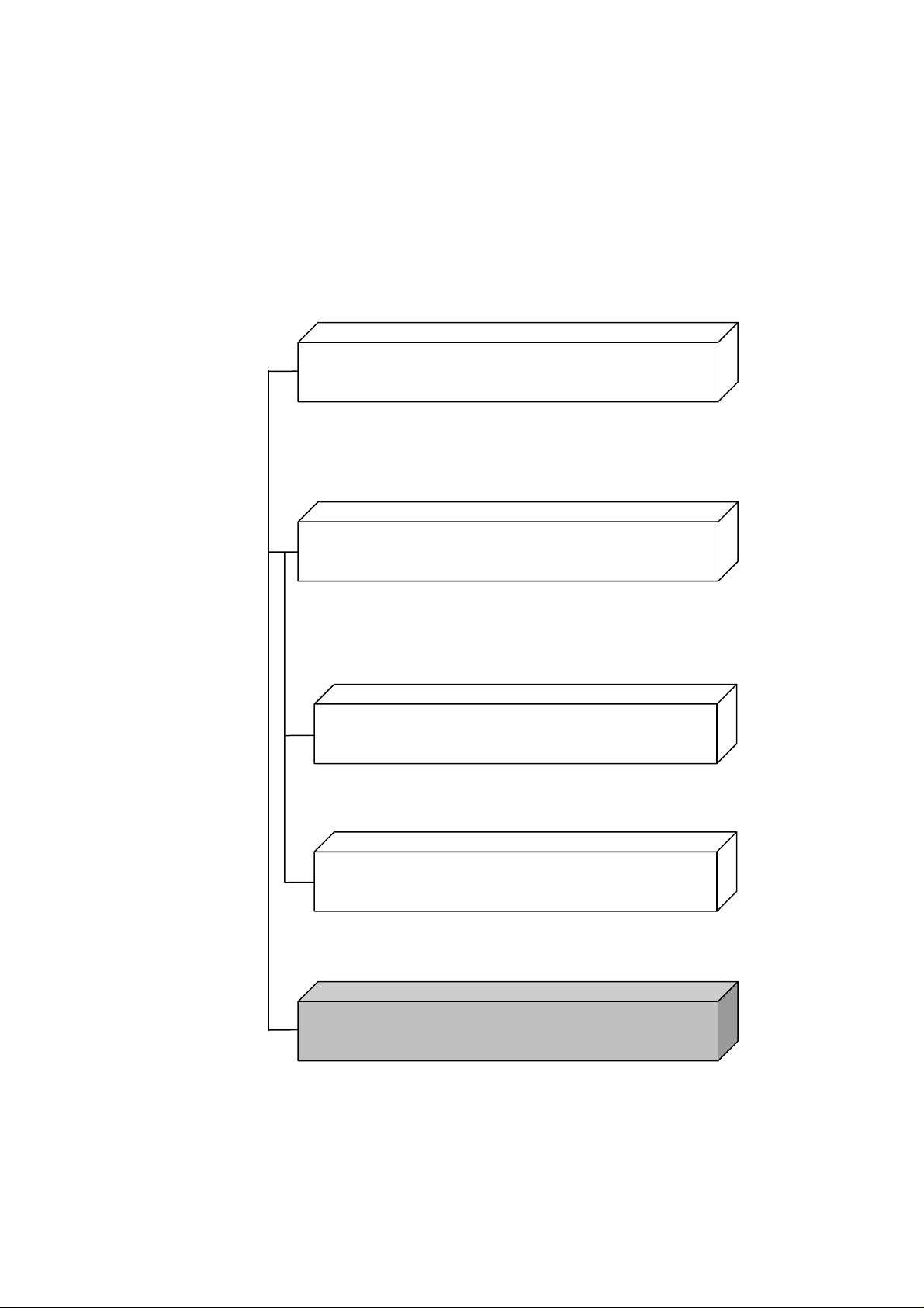
Control of multiple measuring instruments
To measure the characteristics of DUTs via the remote control of multiple
measuring instruments.
1.2 Main Uses for Remote Control
1
Overview
Control PC
E/O
Converter
Optical Fiber
PPG Output
Optical Attenuator
BERTWave
ED1 Input
Optical Receiver
(DUT)
Optical Switch
Optical Power Meter
Figure 1.2-1 Example of Controlling Multiple Instruments
1-3
Page 22

–25.034
0.011442
–24.523
0.0048758
–24.031
0.001631
–23.536
0.00044241
–23.030
0.000078419
–22.523
0.0000088616
–22.031
0.000000616
–21.524
0.000000016
–21.037
0.00000000028235
Chapter 1 Overview
Figure 1.2-1 shows an example of controlling multiple instruments. In
this example, the bit error rates are measured with changes in the optical
input level of the optical receiver. On the control PC, set the attenuation
of the optical attenuator to read the optical power level measured by the
optical power meter, and the bit error rate measured by the BERTWave.
Table 1.2-1 shows the measurement results that are obtained by changing
the optical attenuation.
Table 1.2-1 Bit Error Rate of Optical Receiver
Optical Power (dBm) Bit Error Rate
1-4
Page 23

Overview
1.3 Abbreviations
ASCII
American Standard Code for Information Interchange
CR
Carriage Return
ED
Error Detector
EOI
End or Identify
ESER
Event Status Enable Register
ESR
Event Status Register
GPIB
General Purpose Interface Bus
HiSLIP
High Speed LAN Instrument Protocol
IEC
International Electrotechnical Commission
IEEE
Institute of Electrical and Electronics Engineers
LAN
Local Area Network
LF
Line Feed
MAV
Message Available
MSS
Master Summary Status
OSER
Operation Status Enable Register
OSR
Operation Status Register
PC
Personal Computer
PPG
Pulse Pattern Generator
SCPI
Standard Commands for Programmable Interfaces
SRER
Service Request Enable Register
SRQ
Service Request
STB
Status Byte Register
TR
Transition Filter
VISA
Virtual Instrument Software Architecture
VXI-11
VMEbus Extensions for Instrumentation-11
Table 1.3-1 shows the abbreviations used in this operation manual.
Abbreviation Formal name
1.3 Abbreviations
1
Table 1.3-1 Abbreviations
1-5
Page 24

Chapter 1 Overview
1.4 Restrictions on Software Versions
Some of the commands described in this manual are only available in a
specific version of the MX210000A BERTWave Control Software.
In MP2100B (version 4) and MP2110A (version 5 or later), the
MX210000A version is displayed at the upper right of the application
window.
Figure 1.4-1 Display of Software Version Number (MP2100B, MP2110A)
1-6
Page 25

1.4 Restrictions on Software Versions
Overview
For MP210xA (version 3 or earlier), confirm the version of MX210000A in
Information dialog box of Setup Utility.
1
Figure 1.4-2 Display of Software Version Number (MP210xA,
MP2100B)
1-7
Page 26

Chapter 1 Overview
1-8.
Page 27

Before Use
Chapter 2 Before Use
This chapter explains the preparations for using remote control.
2.1
Connection Types of Remote Controlling .................... 2-2
2.2 Multiple Sessions (Version 5 or later) .......................... 2-3
2.3 Required Equipment ................................................... 2-4
2.4 Connecting Equipment ................................................ 2-5
2.4.1 Connecting Ethernet ....................................... 2-5
2.4.2 Connecting GPIB ............................................ 2-6
2.5 Setting Interface .......................................................... 2-8
2.5.1 MP210xA and MP2100B ................................. 2-8
2.5.2 MP2110A ........................................................ 2-9
2.6 Checking Connection ................................................ 2-10
2.6.1 When using Ethernet (Windows 7) ................ 2-10
2.6.2 When using GPIB.......................................... 2-11
2.7 Message Format ....................................................... 2-12
2.7.1 Message Types ............................................. 2-12
2.7.2 Message Configuration ................................. 2-13
2.7.3 Common Commands .................................... 2-16
2.7.4 Device Dependent Commands ...................... 2-16
2.8 Checking Instrument Status ...................................... 2-17
2.8.1 Register Structure ......................................... 2-17
2.8.2 Status Byte Register ..................................... 2-19
2.8.3 Standard Event Status Register .................... 2-21
2.8.4 Operation Status Register ............................. 2-23
2.8.5 Device Dependent Registers ......................... 2-26
2.9 Checking If Message Execution Is Completed ........... 2-29
2.9.1 When using Ethernet ..................................... 2-29
2.9.2 When using GPIB.......................................... 2-30
2
2-1
Page 28

Raw Socket
TCPIP[0]::<IP address|host
TCPIP::192.168.20.3::5001::SOCKET
VXI-11
TCPIP[0]:: <IP address|host name
TCPIP::192.168.20.3::inst0::INSTR
HiSlip
TCPIP[0]:: <IP address|host name
TCPIP::192.168.20.3::hislip::INSTR
GPIB
GPIB[0]::<primary
address>]::INSTR
GPIB::1::INSTR
Chapter 2 Before Use
2.1 Connection Types of Remote Controlling
The following connections can be performed when controlling BERTWave
remotely.
Raw Socket connection
•
VXI-11 connection (version 5 or later)
•
HiSLIP connection (version 5 or later)
•
GPIB connection
•
Table 2.1-1 lists the resource names when performing the connection
using VISA.
Table 2.1-1 VISA Resource Name List
Protocol VISA Resource Name Example
name>::<Port number>::SOCKET
>::inst0::INSTR
>::hislip[0] [,<Port number >]::INSTR
address>[::<secondary
2-2
Page 29

2.2 Multiple Sessions (Version 5 or later)
Before Use
Raw Socket
30 sessions
VXI-11
30 sessions
HiSLIP
8 sessions
GPIB
1 session
2.2 Multiple Sessions (Version 5 or later)
When Raw Socket, VXI-11, or HiSLIP is used as the protocol, multiple
PCs can connect with MP2110A simultaneously. If the different types of
protocols are used, these PCs are not connected with MP2110A
simultaneously. When controlling the multiple sessions using VXI-11 or
HiSLIP, the session can be locked to perform the exclusion control of the
sessions.
Table 2.2-1 lists the maximum number of sessions for each protocol.
Table 2.2-1 List of Maximum Number of Sessions
2
Protocol
Maximum Number of
Sessions
2-3
Page 30

Chapter 2 Before Use
2.3 Required Equipment
The equipment required for remote control is as follows
Control PC
•
Ethernet interface
•
GPIB interface*
•
Program development tool
•
Control PC
Prepare the PC that meets the operating environment for the GPIB
interface and program development tools.
Ethernet Interface
Prepare Ethernet-compliant interface and cable.
GPIB Interface*
Prepare IEEE 488.2-compliant GPIB interface and cable.
Program Development Tool
Prepare a tool for developing and running programs for performing
remote control. For the requirements specification of the program
development tool, refer to the manuals that come with the tool you
prepared.
VISA is required for using the sample program explained in Appendix C.
*: The option 030 is required for using GPIB in MP210xA and
MP2100B.
2-4
Page 31

Before Use
2.4 Connecting Equipment
Control PC
Connecting via LAN
Control PC
Connect using LAN
Network hub
2.4.1 Connecting Ethernet
Connect the Ethernet connector on the side-panel of the BERTWave and
Control PC using LAN cables.
The Ethernet connector is located on the left side panel for MP210xA and
MP2100B, and on the rear panel for MP2110A
Use a LAN cable to connect the BERTWave and Control PC directly. Use a
LAN cable via a network hub when connecting to multiple external
devices.
2.4 Connecting Equipment
2
cable
Figure 2.4.1-1 Direct Connection between BERTWave and Control PC
cables.
External device
Figure 2.4.1-2 Sample Connection with Multiple External Devices
Notes:
MP210xA and MP2100B cannot connect to the network
•
including the address range from 192.168.1.0 to 192.168.1.255.
The control PC may have difficulty in communicating with the
•
BERTWave, depending on the status of communications
between them. The direct connection is recommended to ensure
communication stability.
2-5
Page 32

GPIB
GPIB connector
GPIB cable
Total cable length: Up to 20 m
Number of devices that can be connected: Up to 15
Chapter 2 Before Use
2.4.2 Connecting GPIB
Connect the GPIB connector on the rear panel of the BERTWave and an
external device using a GPIB cable.
Up to 15 devices, including the control PC can be connected to one
BERTWave unit. Always follow the conditions shown below when
connecting devices.
CAUTION
Always connect the GPIB cable BEFORE turning on the
power to the BERTWave. Connecting it while the power is
on may damage internal circuits.
Cable length between devices: Up to 4 m
2-6
Figure 2.4.2-1 GPIB Cable Connection 1
Page 33

Before Use
Connect cables without forming loops.
(a) Daisy Chain
(b) Star
(c) Loop
2.4 Connecting Equipment
2
Figure 2.4.2-2 GPIB Cable Connection 2
2-7
Page 34

Chapter 2 Before Use
2.5 Setting Interface
For details on how to set the interface, refer to 2.14 “Setting Interface for
Remote Control” in the
4.3.10 “Remote Control” in the
2.5.1 MP210xA and MP2100B
1. Switch on the power to the MP210xA or MP2100B.
MP2100B BERTWave Operation Manual
MP2110A BERTWave Operation Manual
and
.
2. Touch
3. Touch
4. In order to use Ethernet, touch the Active Interface button to set the
button display to
GPIB.
When the Option 030 is not installed, the Active Interface button is
disabled.
5. When using Ethernet, set the IP address, subnet mask, gateway and
port number.
The gateway address can be omitted.
The port number can be set from 1024 to 5001.
When using GPIB, set the GPIB address.
6. Touch Apply, and then the settings are completed.
Touch
Note:
Setup Utility at the Selector screen.
Remote Control.
Ethernet. To use GPIB, set the button display to
Exit, and then the set value is deleted.
Do not set the following IP address.
192.168.1.xxx
2-8
Page 35

Before Use
2.5.2 MP2110A
2.5 Setting Interface
1. Switch on the power to the MP2110A.
2. Click
3. Click
4. Set the GPIB address, IP address, subnet mask, gateway and port
5. Click
Note:
System Menu.
Remote Control.
number.
The gateway address can be omitted.
The port number can be set from 1024 to 5001.
OK, and then the settings are completed.
Click Cancel, and then the set value is deleted.
Do not set the following IP address.
169.254.1.xxx
2
2-9
Page 36

Chapter 2 Before Use
2.6 Checking Connection
This section describes how to check if the Control PC can recognize the
BERTWave.
For MP210xA and MP2100B, start Main Application before checking the
connection.
1. If the Setup Utility dialog box is displayed, touch
Exit.
2. On the Selector screen, touch
2.6.1 When using Ethernet (Windows 7)
This section explains how to use the free software, Tera Term Version
4.69.
1. When starting Tera Ter m , the
Enter the IP address and TCP port number in the Host.
Set the service to
Click OK.
If the BERTWave IP address is set to 192.168.100.2, and the port
number is set to 5001, set as follows.
Other and protocol to IPv4.
Main Application.
New connection window is opened.
2-10
2. When Ter a Te r m recognizes the BERTWave, the communication
window is displayed.
3. Click
Settings (S) - Terminal (T).. on the menu.
Page 37

2.6 Checking Connection
Before Use
4. Under New-line, set Receive to LF and Transmit to CR+LF. Select
the Local echo check box and click OK.
5. Send *IDN?.
Confirm that the response is displayed from the BERTWave.
2
2.6.2 When using GPIB
1. Install the software drivers for the GPIB interface.
2. Run the software.
For the operation method, refer to the GPIB interface operation
manual.
3. Check the displayed instrument address.
2-11
Page 38

Chapter 2 Before Use
2.7 Message Format
2.7.1 Message Types
Messages are composed of the character strings indicating message and
message end. The character string indicating the message end is LF (Line
Feed) or CR (Carriage Return) +LF.
Note:
If LF or CR+LF is not attached to the message end, a timeout error
occurs because the communication does not end.
Messages are composed of the following types depending on the
transmission direction:
Program Messages
Messages sent from control PC to instrument
There are two types of the program messages:
Command
•
This can be used for measurement condition settings and
measurement start.
Query
•
This queries the status and settings of the measuring instrument.
When transmitting the query, the instrument creates a response
message to the query.
Response Messages
Messages sent from instrument to control PC
2-12
Page 39

Before Use
2.7.2 Message Configuration
The messages are composed of header and data parts separated by more
than a half width space. Program messages always have a header but
sometimes have no data. Response messages always have data but
sometimes have no header.
Header
The command header has the following types:
Simple header
•
The header is composed of alphanumeric characters and underbars,
and the initial character is an alphabetic character.
Example:
Common command header
•
The header is composed of alphanumeric characters and underbars,
and the initial character is an asterisk (*).
Example:
Multiple headers
•
Single headers are linked by colons. Colons can be used at the header.
Multiple headers can be used to configure layered processing.
Example:
Queries have a question mark (?) appended to the header.
STA
*CLS
:SENSE:MEASURE:START
2.7 Message Format
2
Example:
:CONFIGURE?
Data
The data format is character string data, numeric data, and binary data.
String data is ASCII code enclosed in quotation marks.
An example of the program message when inputting
the title is shown below.
Example:
:SYSYEM:MEMORY:STORE 'Model ANR-005',0,ALL
:SYESEM:MEMORY:STORE "Model ANR-005",0,ALL
When quotation marks are included in the character string, paired marks
are used.
Example:
He said "Good product". → "He said ""Good Product""."
He said 'Good product'. → 'He said ''Good Product''.
'
*ESE?
Model ANR-005
at
2-13
Page 40

Chapter 2 Before Use
In addition, paired quotation marks can be used inside other paired
quotation marks.
Example:
He said "Good product". → 'He said "Good Product".'
He said 'Good product'. → "He said 'Good Product'."
The numeric values can be described by using numeric data, input
numeric values either as decimal, binary, octal, or hexadecimal numbers.
When using the binary, octal, or hexadecimal numbers, put #B, #O, or #H
before the data.
Example:
When using decimal numbers, use integer number, fixed point, or floating
point. The following examples indicate the same values.
Example:
For the binary data, the head string starts with a sign (#) and continues
with data after a numeric value indicating the data length.
Example:
4 digits 2002 bytes binary data
10 #B1010 #O12 #HA
1550 #B11000001110 #O3016 #H60E
-10 -10.00 -1E1
1250 1250.000 1.25E3
0.0023 2.3E-4
#42002an%*qe4445+\…
2-14
Page 41

2.7 Message Format
Before Use
When there are multiple data in a message, separate each of them with
commas (,).
Example:
:SENSE:MEASURE:EALARM:PERIOD 0,0,1,0
When concatenating multiple program messages, separate the messages
with semicolons (;).
Example:
Note:
When sending multiple messages separated by semicolons, the
maximum length of the concatenated string is 1024 bytes.
When sending a concatenated string of query messages, response
messages are separated by semicolons.
Example:
:INPUT:DATA:ATTFACTOR 1,6
:MOD:ID 5;:DISP:MODE EYE;:SAMP:STAT RUN
:MOD:ID 1;:OUTP:BITR:STAN?;:OUTP:BITR?
>"10G_LAN";10312500
2
2-15
Page 42

*CLS
Clears stand event register and output queue
*ESE
Sets and queries standard event enable register
*ESR
Queries standard event register
*IDN
Queries product information
*OPC
Sets/queries bit setting and bit 0 for status byte
indicating message processing completion
*OPT
Queries option information
*RST
Initializes BERTWave setting conditions
*SRE
Sets and queries SRER
*STB
Queries status byte register
*TRG
Starts measurement
*WAI
Waits previous sent message completion
Chapter 2 Before Use
2.7.3 Common Commands
The GPIB specifications (IEEE 488.2) define equipment commands. In
this manual, these defined commands are called common commands.
The common commands are divided into mandatory and option
commands. The BERTWave supports the common commands listed in
Table 2.7.3-1.
Command Explanation
Table 2.7.3-1 Common Commands
2.7.4 Device Dependent Commands
In this manual, commands that differ according to the functions of the
measuring instrument are called Device Dependent Commands.
This instrument has two types of Device Dependent Commands.
SCPI
•
Commands meeting SCPI standard
Native
•
Commands consisting of at least three ASCII characters
2-16
Page 43

Before Use
2.8 Checking Instrument Status
Status Byte Register
Output Queue
Bit
0
Bit
Standard Event Status Register
Power On
Execution Error
Query Error
Logical Sum
Not Used
Bit
0
Operation Status Register
Not Used
Logical Sum
MAV
Logical Sum
Generating
Service Request
Status Register
Bit
Bit
Bit
0
Device Dependent Register
Not Used
CAL Alarm (Yellow)
Not Used
PLL Unlock
Not Used
LOS
Bit
Bit
Bit
*: Version 6 or later
The BERTWave has registers indicating status, such as errors and
command execution status. This section explains these registers.
2.8 Checking Instrument Status
2.8.1 Register Structure
Figure 2.8.1-1 shows the structure of the registers indicating the
instrument status.
15
Not Used
Not Used
Not Used
Not Used
Not Used
Not Used
Not Used
Not Used
Not Used
ED measurement
Not Used
Not Used
Not Used
Not Used
Not Used
Command Error
Not Used
Operation Complete
14
13
12
11
10
9
8
7
6
5
4
3
2
1
7
6
5
4
3
2
1
0
Insertion Error
CR Unlock
SYNC Loss
Bit Error
Not Used
Not Used
Not Used
PPG/ED Ch1 to Ch4
Status Register
15
15
:
:
5
5
4
4
3
3
2
2
1
1
0
0
XFP/SFP+
15
:
4
3
2
PT phase unlock
1
0
CAL Alarm (Red)
15
15
:
:
5
5
4
4
3
3
2
2
1
1
0
0
Scope
Status Register
CRU Unlock*
Not Used
Not Used
2
15
:
8
7
6
5
4
3
2
1
MSS
ESB
Not Used
Not Used
Figure 2.8.1-1 Register Structure
7
6
5
4
3
2
1
2-17
Page 44

0 1 8
256
1 2 9
512
2 4 10
1024
3 8 11
2048 4 16
12
4096 5 32
13
8192 6 64
14
16382
7
128
15
32764
Chapter 2 Before Use
Each register uses 8-bit or 16-bit data. The register output values are the
decimal totals for each bit shown in Table 2.8.1-1.
Table 2.8.1-1 Register Bit Decimal Conversion Values
Bit
The register has a corresponding bit enable register.
Decimal
value
Bit
Decimal
value
2-18
Page 45

Before Use
2.8.2 Status Byte Register
Bit
7
6
5
4
3
2
1
0
Status Byte Register
Execution Status
Standard Event Status
Send Queue
Not used
Query Error
Not used
Not used
Logical Sum
Bit
7
6
5
4
3
2
1
0
Service Request
Enable Regist
er
Service
Request
Logical
Product
The status byte register (STB) displays the status of equipment defined
by the GPIB standards. When the equipment status changes, the value in
the STB changes too. It can be used to generate interrupts to the Control
PC. These interrupts are called service requests.
There is a service request enable register (SRER) for the STB. The SRER
can select the status byte bit generating the service request.
2.8 Checking Instrument Status
2
Figure 2.8.2-1 Configuration of Status Byte Register and Service
Request Enable Register
Note:
When using the GPIB interface, the service request is enabled.
The following methods are used to read the status byte register.
Using common *STB? command
•
Using GPIB serial poll (when the Option 030 is installed for MP210xA
•
or MP2100B)
Read the GPIB interface manual for the serial poll method.
When using serial polling, even if bit 6 is 1, it becomes 0 after reading
once.
The
*SRE
and
*SRE?
common commands can be used for setting and
reading the SRER for setting reading of the status byte register. To output
the STB data, set the bit corresponding to the SRER to 1.
2-19
Page 46

7
This is the logical sum of each bit of the logical product of
the OSR and its event enable register.
6
MSS (Master Summary Register)
of the STB and the SRER.
5
This is the logical sum of each bit of the logical product of
enable register.
4
MAV (Message Available summary)
3
Not used; always 0
2
Becomes 1 at System Error
1
Not used; always 0
0
Not used; always 0
Chapter 2 Before Use
The definition of each bit of the STB is shown in the following table.
Table 2.8.2-1 Bit Definition of Status Byte Register
Bit
It is the logical sum of the bit 5 to 0, bit 7 logical product
the standard event status register and standard event
This is always 1 when there is a response message in the
output queue of this instrument
Bit 7 of the STB indicates information about the OSR.
For details about the information, refer to section 2.8.4 “Operation Status
Register”.
Bit 6 of the STB is called the master summary status (MSS) bit. When it
is 1, there is a notification from BERTWave to the control PC. When it
changes to 1 from 0, a service request is generated.
Explanation
Bit 5 of the STB indicates information about the standard event register.
For details about the information, refer to section 2.8.3 “Standard Event
Status Register”.
The device dependent register data is not indicated in the STB.
Bits 7 and 5 of the STB can be set to 0 using the *CLS common command.
When *CLS is sent after a command or when a query is sent after *CLS,
the send queue is cleared and bit 4 is set to 0.
The SRER cannot be set to 0 by *CLS, so use *SRE.
2-20
Page 47

Before Use
2.8.3 Standard Event Status Register
Bit
7
6
5
4
3
2
1
0
Standard Event Status
Register
Power-on
Not used
Command error
Execution error
Device dependent error
Not used
Not used
Operation completed
Logical Sum
Bit
7
6
5
4
3
2
1
0
Standard Event Status
Enable Register
Status Byte
Register bit 5
Logical
Product
There is a standard event status enable register (ESE) for the standard
event status register (ESR). The logical product of these two registers and
the logical sum of each bit of this result is output to bit 5 of the STB.
2.8 Checking Instrument Status
2
Figure 2.8.3-1 Configuration of Standard Event Status Register and
Standard Event Status Enable Register
2-21
Page 48

7
1 if the BERTWave is powered on.
6
Not used; always 0
5
1 if a command error occurs.
Refer to Appendix B, “Error Codes” for details.
4
1 if an execution error occurs.
Refer to Appendix B, “Error Codes” for details.
3
1 if a device-dependent error occurs.
Refer to Appendix B, “Error Codes” for details.
2
Not used; always 0
1
Not used; always 0
0
Operation Complete
sending response data to a query has ended.
Chapter 2 Before Use
The definition of each bit of the ESR is listed in the table below.
Table 2.8.3-1 Bit Definition of Standard Event Status Register
Bit
Changed to 0 if a program message is received.
Becomes 1 when the entire command operation has
completed after *OPC command operation or when
Bit 7 to bit 0 of the ESR can be read by the
The standard event register returns to 0 when read.
The ESE can be set and read using the
output standard event register data, set the bit corresponding to the
enable register to 1.
Explanation
*ESR?
*ESE
and
command.
*ESE?
commands. To
2-22
The bit 0 can be read using the
The standard register can be set to 0 using the
*OPC
command.
*CLS
command.
Page 49

Before Use
2.8.4 Operation Status Register
The operation status register (OSR) is composed of the following registers:
Operation status condition register
•
Transition filter
•
Operation status event register
•
Operation status enable register (OSER)
•
The operation status condition register indicates changes in the status.
When the status changes, the value of this register also changes.
The OSER records changes in the value of the execution status condition
register. There is a transition filter that defines the write condition before
the OSER. The transition filter sets the OSER to 1 under any of the
following conditions:
2.8 Checking Instrument Status
2
When bit changes from 0 to 1
•
When bit changes from 1 to 0
•
When bit changes from 0 to 1 and bit changes from 1 to 0
•
The OSER sets the OSER output at each bit. The logical product of these
two registers is obtained and the logical sum of each bit of the result is
output at bit 7 of the STB.
2-23
Page 50

Bit
15
14
13
12
11
10
9
8
7
6
5
4
3
2
1
0
Operation Status
Event Register
Not used
Not used
Not used
Not used
During PPG/ED pattern setting
Not used
Not used
Not used
Not used
Not used
Not used
During ED Measuring
Not used
Not used
Not used
Not used
Logical Sum
Bit
15
14
13
12
11
10
9
8
7
6
5
4
3
2
1
0
Operation Status
Enable Register
Status Byte
Register Bit 7
Logical
product
Bit
15
14
13
12
11
10
9
8
7
6
5
4
3
2
1
0
Transition Filter
Detecting
Status Change
Bit
15
14
13
12
11
10
9
8
7
6
5
4
3
2
1
0
Operation Status
Condition Register
15 to 12
Not used; always 0
11
1 during execution of PPG/ED pattern setting.
10 to 5
Not used; always 0
4
1 during execution of ED measurement.
3 to 0
Not used; always 0
Chapter 2 Before Use
Figure 2.8.4-1 Configuration of Operation Status Condition Register, Operation Status Event
Register, Operation Status Enable Register, and Transition Filter
Each bit definition of the execution status is as follows.
2-24
The commands for confirming the execution start or end time at the OSR
are shown in the following table.
Table 2.8.4-1 Bit Definition of Operation Status Register
Bit
Explanation
Page 51

2.8 Checking Instrument Status
Before Use
11
:SENSe:MMEMory:PATTern:RECall
:SOURce:PATTern:TYPE
4
[:BERT:ALL]:SENSe:MEASure:STARt
Table 2.8.4-2 Commands for Confirming Execution of operation at
Operation Status Register
Operation
Status
Register Bit
Command
:SENSe:PATTern:TYPE
:SOURce:MMEMory:PATTern:RECall
[:BERT:ALL]:SENSe:MEASure:STOP
To detect the execution start, set the corresponding bit of the transition
filter to 1 using STATus:OPERation:PTRansition
To detect the execution end, set the corresponding bit of the transition
filter to 1 using STATus:OPERation:NTRansition.
The OSER can be read using :STATus:OPERation[:EVENt]?. When the
register is read, the OSR returns to 0.
The operation status condition register can be read
using :STATus:OPERation:CONDition?.
To set the OSER, use :STATus:OPERation:ENBle. To read the OSER, use
STATus:OPERation:ENBle?. To output the OSR data, set the bit for the
status setting enable register to 1.
When sending :STATus:OPERation:RESet, the operation status event
register is set to 0.
However, sending :STATus:OPERation:RESet does not reset the OSER.
2
2-25
Page 52

Not used
Not used
Not used
Not used
Not used
Not used
Not used
Not used
Detecting Status Change
Chapter 2 Before Use
2.8.5 Device Dependent Registers
The following registers are called the device dependent registers.
PPG/ED Ch1 to 4 Status Register
•
XFP/SFP+ Status Register
•
Scope Status Register
•
The device dependent register has condition register, transition filter, and
event register as the operation status register does. However there is no
enable register for switching the output at each bit on/off.
Device Dependent
Condition Register
Bit
15
14
Not used
Not used
Not used
Not used
Not used
Status 2
Status 1
Status 0
13
12
11
10
9
8
7
6
5
4
3
2
1
0
Transition Filter
Bit
15
14
13
12
11
10
9
8
7
6
5
4
3
2
1
0
Device Dependent
Event Register
Bit
15
14
13
12
11
10
9
8
7
6
5
4
3
2
1
0
2-26
Figure 2.8.5-1 Configuration of Device Dependent Register
When the value of the device dependent register changes, there is no
effect on the STB. As a result, a service request is not generated to the
control PC.
Page 53

2.8 Checking Instrument Status
Before Use
15 to 6
Not used; always 0
5
Indicates Omission Error occurs.
4
Indicates Insertion Error occurs.
3
Indicates CR Unlock occurs.
2
Indicates SYNC Loss occurs.
1
Indicates Bit Error occurs.
0
Indicates PLL Unlock occurs.
15 to 2
Not used; always 0
1
Indicates LOS occurs.
0
Indicates Ready status.
15 to 9
Not used; always 0
8
Not used; always 0
7
Indicates CRU Unlock occurs.*1
6
Indicates that Precision Trigger is out of synchronized
5
Indicates that the frequency of trigger input signal is
abnormal. *2
4
Indicates PLL Unlock (No trigger input) occurs.
3
Not used; always 0
2
Indicates CAL alarm (Orange) occurs.
1
Indicates CAL alarm (Red) occurs.
0
Indicates CAL alarm (Yellow) occurs.
Each bit definition of the device dependent register is as follows.
Table 2.8.5-1 Bit Definition of PPG/ED Ch1 to Ch4 Status Register
Bit
Explanation
2
Table 2.8.5-2 Bit Definition of XFP/SFP+ Status Register
Bit
Table 2.8.5-3 Bit Definition of Scope Status Register
Bit
Explanation
Explanation
status. *2
*1: Software version 6 or later
*2: Software version 5 or later
To detect the occurrence of these phenomena, set the transition filter bit
to 1 using the following commands:
:INSTrument:PE{1|2|3|4}:PTRansition
:INSTrument:XSFP:PTRansition
:INSTrument:WAV:PTRansition
To detect the end of these phenomena, set the transition filter bit to 1
using the following commands:
2-27
Page 54

Chapter 2 Before Use
:INSTrument:PE{1|2|3|4}:NTRansition
:INSTrument:XSFP:NTRansition
:INSTrument:WAV:NTRansition
The device dependent event register can be read using the following
queries:
:INSTrument:PE{1|2|3|4}[:EVENt]?
:INSTrument:XSFP[:EVENt]?
:INSTrument:WAV[:EVENt]?
The device dependent condition register can be read using the following
queries:
:INSTrument:PE{1|2|3|4}:CONDition?
:INSTrument:XSFP:CONDition?
:INSTrument:WAV:CONDition?
The device dependent event register can be initialized using the following
queries:
:INSTrument:PE{1|2|3|4}:RESet
:INSTrument:XSFP:RESet
:INSTrument:WAV:RESet
2-28
Page 55

2.9 Checking If Message Execution Is Completed
Before Use
2.9 Checking If Message Execution Is Completed
Some of the BERTWave program messages may take several seconds to
several ten seconds to execute. Depending on the interface (Ethernet or
GPIB) you are using, the procedure to check if time-consuming message
execution is completed is different.
2.9.1 When using Ethernet
Even during execution of a program message sent to the BERTWave, the
subsequent message(s) can be sent. However, until execution of the
previously sent message(s) is completed, the subsequent message(s) is not
processed, and is stored in the buffer of the BERTWave.
Therefore, note that execution of the previously sent program message(s)
may not have always been completed, even if the subsequent message(s)
can be sent. To check if execution of a program message is completed, send
a query to receive a response.
Example:
:CALibrate:AMPLitude
:SYSTem:ERRor?
> 0,”No Error”
It may take around 50 seconds to complete execution of
:CALibrate:AMPLitude
the
version 5 or later).
subsequently
AMPLitude
is checked by receiving a response message.
AMPLitude
:SYSTem:ERRor?
Starts Level calibration for Scope
Query for error code and error message
No error
command in this example (in software
is sent, and
, and then execution completion of
2
Note:
If it may take a long time to process the command that precedes the
query, set the sufficient response timeout, with respect to the
command processing time. (Timeout needs to be longer by at least
10 seconds than the command processing time.)
2-29
Page 56

Chapter 2 Before Use
2.9.2 When using GPIB
Sending the subsequent message is forced to wait, on the control PC, until
execution of the sent message is completed. Therefore, prevent a
communication timeout from occurring during message execution by the
BERTWave, when sending a time-consuming command. Set the sufficient
timeout for GPIB interface of the control PC, with respect to the command
processing time. (Timeout needs to be longer by at least 10 seconds than
the command processing time.)
Example: Sending a command that takes about 20 seconds to execute
1. Set the timeout for GPIB interface to 30 seconds.
2. Send a command which takes time to complete.
3. Reset the timeout to the previous setting.
2-30.
Page 57

Message List
Chapter 3 Message List
This chapter describes the message details of remote control commands
for BERTWave.
3.1
Rules for Describing Messages ................................... 3-3
3.2 Correspondence Between Panel and Messages ......... 3-4
3.2.1 Messages corresponding to
common operations ......................................... 3-4
3.2.2 Messages corresponding to PPG/ED .............. 3-6
3.2.3 Messages corresponding to XFP/SFP+
(MP210xA, MP2100B) ................................... 3-13
3.2.4 Messages corresponding to O/E
(MP210xA, MP2100B) ................................... 3-14
3.2.5 Messages corresponding to Scope ................ 3-15
3.2.6 Messages corresponding to Information ........ 3-41
3.2.7 Messages with no corresponding
panel operation ............................................. 3-42
3.3 Messages Corresponding to Common Operations..... 3-43
3.3.1 Setting system configuration.......................... 3-43
3.3.2 Obtaining system information ........................ 3-45
3.3.3 System alarm (MP210xA, MP2100B) ............ 3-50
3.3.4 Resetting/recalling settings ............................ 3-52
3.3.5 Storing settings and results ........................... 3-54
3.3.6 Turning on/off plotting processing .................. 3-56
3.3.7 Screen Copy ................................................. 3-57
3.3.8 Specifying screen display .............................. 3-60
3.4 Status Register ......................................................... 3-61
3.4.1 Clearing register ............................................ 3-61
3.4.2 Status byte register ....................................... 3-63
3.4.3 Standard event status register ....................... 3-65
3.4.4 Operation status register ............................... 3-67
3.4.5 PPG/ED status register ................................. 3-71
3.4.6 Scope status register..................................... 3-75
3.4.7 XFP/SFP+ status register .............................. 3-78
3.4.8 Register operation without
dependence on module ................................. 3-81
3.5 Specifying Module and Channel ................................ 3-84
3.5.1 Specifying with command .............................. 3-84
3.5.2 Specifying in header (Added in Version 3.02) 3-85
3.6 BERT(PPG/ED) Messages ....................................... 3-86
3.6.1 Window Operation......................................... 3-86
3.6.2 Clock Input .................................................... 3-87
3.6.3 Clock Output ................................................. 3-91
3.6.4 Tracking Setting ............................................ 3-93
3.6.5 Bit Rate Setting ............................................. 3-95
3
3-1
Page 58

Chapter 3 Message List
3.6.6
3.6.7 PPG ............................................................ 3-110
3.6.8 ED .............................................................. 3-115
3.7 XFP/SFP+ specific Messages
(MP210xA, MP2100B) ............................................ 3-134
3.8 O/E messages ........................................................ 3-137
3.9 Scope-specific messages ........................................ 3-138
3.9.1 Setting active channel and On/Off display ... 3-138
3.9.2 Basic operation ........................................... 3-142
3.9.3 Setup .......................................................... 3-145
3.9.4 Time ........................................................... 3-166
3.9.5 Amplitude, O/E ............................................ 3-182
3.9.6 Measure ...................................................... 3-200
3.9.7 Acquiring results ......................................... 3-232
3.9.8 Marker ........................................................ 3-248
3.9.9 Jitter ............................................................ 3-251
Test Pattern Setting .................................... 3-104
3-2
Page 59

Message List
3.1 Rules for Describing Messages
<>
Parameters in angled bracket are input by the programmer.
[]
Messages or parameters in square brackets can be omitted.
|
Select one of choices separated by vertical bars. For example,
if A|B|C|D are choices, select one of them.
{}
Group the choices. For example, A|B({C|D}) means that A,
B(C), or B(D) is available.
<binary_data>
This string is in binary data format.
<character>
Alphabet or numeric characters
<file_name>
The string indicates file name and path. The double
Example:
"PATTERN005"
<integer>
Decimal integer
Example: –100, 12500000
<numeric>
Decimal number
Example: 0, 1.2E–6, 2.35
<string>
String data
needed at the beginning and end of the data.
<enable>
On/Off setting
Example: 0, 1, OFF, ON
…
Indicates that multiple parameters or responses are omitted.
>
Precedes a response, in Example of Use.
The following table shows the rules for describing messages.
Table 3.1-1 Rules for Describing Messages
Symbols Usage
quotation marks or single quotation marks are needed at the
beginning and end of the data.
\,/,:,*,?,",<,>,| are not used in the file name.
3.1 Rules for Describing Messages
3
The double quotation marks or single quotation marks are
To turn off, specify 0 or OFF. (Response: 0)
To turn on, specify 1 or ON. (Response: 1)
Some parts of the header strings can be omitted.
The lower-case characters can be omitted, but the upper-case characters
cannot be omitted.
Example:
The following header strings are also acceptable:
:STAT:OPER:EVEN?
:STAT:OPERATION:EVEN?
:STATUS:OPERAT:EVENT?
:STATUS:OPERATION:EVEN?
:STATUS:OPERATION:EVENT?
BERTWave interprets them in the same way.
:STATus:OPERation:EVENt?
3-3
Page 60

:DISPlay:ACTive
:SYSTem:ERRor:HISTory?
:SOURce:OUTPut:ASET
:SENSe:MEASure:ASTP
:SENSe:MEASure:ASTate?
*TRG
:SYSTem:{DATE|TIME}?
:BERT:ALL:PARam:TRACking
:DISPlay:ACTive:ACResult
*IDN?
:SYSTem:MMEMory:STORe
:SYSTem:PRINt:COPY
:SYSTem:BEEPer:SET
*RST
:SYSTem:MMEMory:RECall
:SYSTem:DISPlay:ALARm
:SYSTem:MMEMory:STORe
:SYSTem:PRINt:COPY
*RST
:SYSTem:MMEMory:RECall
Chapter 3 Message List
3.2 Correspondence Between Panel and Messages
This section explains correspondence between panel and messages.
3.2.1 Messages corresponding to common operations
Figure 3.2.1-1 Messages Corresponding to Common Operations
Figure 3.2.1-2 Messages Corresponding to System Menu (MP210xA, MP2100B)
3-4
Figure 3.2.1-3 Messages Corresponding to System Menu (MP2110A)
Page 61

3.2 Correspondence Between Panel and Messages
Message List
SYSTem:ERRor:HCLear
:SYSTem:ERRor:HISTory?
:SYSTem:DISPlay:ALARm
:SYSTem:INFormation:ERRor?
3
Figure 3.2.1-4 Messages Corresponding to System Alarm Dialog Box (MP210xA, MP2100B)
3-5
Page 62

:OUTPut:DATA:AMPLitude
:OUTPut:DATA:OUTPut
:SOURce:PATTern:TYPE
:OUTPut:BITRate:OFFSet
:OUTPut:BITRate:STANdard
:OUTPut:BITRate
:OUTPut:DATA:RELative?
:OUTPut:DATA:ATTFactor
:SOURce:MMEMory:PATTern:
RECall
:SOURce:PATTern:DATA:
LENGth?
:SOURce:PATTern:LOGic
:OUTPut:BITRate:DIVRate
:OUTPut:CMU:EXTClock
:OUTPut:RCLock
:OUTPut:SYNC:SOURce
:SOURce:PATTern:EADDition:SET
:SOURce:PATTern:EADDition:VARiation
:SOURce:PATTern:EADDition:RATE
:SOURce:PATTern:EADDition:SINGle
:OUTPut:RCLock:STATu s ?
:OUTPut:RCLock:APPLy
:OUTPut:RCLock:SELect
Chapter 3 Message List
3.2.2 Messages corresponding to PPG/ED
When controlling PPG/ED, add :BERT[<ch>] to the beginning of the
message header or specify a channel using the :MODule:ID command.
Refer to Section 3.5, “Specifying Module and Channel” for details.
3-6
Figure 3.2.2-1 Messages Corresponding to PPG Panel (MP210xA,
MP2100B)
Page 63

Message List
:INPut:DATA:INTerface
:INPut:DATA:THReshold
:SENSe:PATTern:TYPE
:INPut:BITRate:STANdard
:INPut:BITRate
:INPut:DATA:ATTFactor
:SENSe:MMEMory:PATTern:
RECall
:SENSe:PATTern:DATA:LENGth?
:SENSe:PATTern:LOGic
:SENSe:MEASure:EALarm:STARt?
:SENSe:MEASure:EALarm:ELAPsed?
:SENSe:MEASure:EALarm:TIMed?
[:BERT:ALL]:CALCulate
:DATA:EALarm?
:SENSe:PARam:TRACking
:INPut:BITRate:DIVRate?
:SENSe:MEASure:EALarm:STOP?
[:BERT:ALL]:CALCulate:DATA:MONitor?
[:BERT:ALL]:SENSe:MEASure
:EALar
[:BERT:ALL]:SENSe:MEASure:
STARt
[:BERT:ALL]:SENSe:MEASure:
STOP
[:BERT:ALL]:SENSe:
MEASure:IMMediate?
[:BERT:ALL]:DISPlay:RESult
:EALarm:HRESet
3.2 Correspondence Between Panel and Messages
3
m : STATe ?
Figure 3.2.2-2 Messages Corresponding to ED Panel–1 (MP210xA, MP2100B)
3-7
Page 64

Chapter 3 Message List
:SENSe:PATTern:SYNC:ASYNc
:SENSe:PATTern:SYNC:THReshold
:SENSe:PATTern:SYNC:PSMode
:SENSe:PATTern:SYNC:FPOSition
:OUTPut:SYNC:SOURce
:SENSe:MEASure:EALarm:MODE
:SENSe:MEASure:EALarm:PERiod
:DISPlay:RESult:EALarm:MODE
Figure 3.2.2-3 Messages Corresponding to ED Panel–2 (MP210xA, MP2100B)
3-8
Page 65

3.2 Correspondence Between Panel and Messages
Message List
:OUTPut:DATA:AMPLitude
:OUTPut:BITRate:OFFSet
:OUTPut:DATA:ATTFactor
:SOURce:PATTern:LOGic
:SENSe:PATTern:LOGic
:SENSe:MEASure:EALarm:STARt?
:SENSe:MEASure:EALarm:ELAPsed?
:SENSe:MEASure:EALarm:TIMed?
:SENSe:MEASure:EALarm:STOP?
[:BERT:ALL]:SENSe:MEASure:
EALarm:STATe?
[:BERT:ALL]:CALCulate:DATA:MONitor?
:INPut:DATA:ATTFactor
:INPut:DATA:THReshold
:SENSe:PATTern:TYPE
:INPut:DATA:INTerface
:OUTPut:DATA:RELative?
:OUTPut:DATA:OUTPut
:SOURce:PATTern:TYPE
[:BERT:ALL]:CALCulate:D
ATA:EALarm?
:SENSe:PARam:TRACking
:OUTPut:BITRate:STANdard
:DISPlay:RESult
:OUTPut:BITRate
:OUTPut:BITRate
:OUTPut:RCLock:APPLy
:OUTPut:RCLock:STATu s ?
[:BERT:ALL]:SENSe:MEASure:
STARt
[:BERT:ALL]:SENSe:MEASure:
STOP
[:BERT:ALL]:SENSe:M
EASure:IMMediate?
[:BERT:ALL]:DISPlay:RESult:E
ALarm:HRESet
[:BERT:ALL]:CALCulate:DATA:MONitor:HISTory?
3
Figure 3.2.2-4 Messages Corresponding to PPG/ED Panel–1 (MP2110A)
3-9
Page 66

:SENSe:MEASure:EALarm:MODE
:DISPlay:RESult:EALarm:MODE
:SENSe:MEASure:EALarm:PERiod
:OUTPut:SYNC:SOURce
:OUTPut:RCLock
:OUTPut:CLOCk:DIVRate?
:SOURce:PATTern:EADDition:SINGle
:OUTPut:CLOCk:SOURce:CHANnel
Chapter 3 Message List
Figure 3.2.2-5 Messages Corresponding to PPG/ED Panel–2 (MP2110A)
3-10
Page 67

3.2 Correspondence Between Panel and Messages
Message List
[:BERT:ALL]:SENSe:MEASure:STARt
[:BERT:ALL]:SENSe:MEASure:STOP
[:BERT:ALL]:SENSe:MEASure:IMMediate?
[:BERT:ALL]:CALCulate:DATA:MONitor?
3
Figure 3.2.2-6 Messages Corresponding to All BER Measurement-1
3-11
Page 68

[:BERT:ALL]:CALCulate:DATA:EALarm?
[:BERT:ALL]:DISPlay:RESult:EALarm:HRESet
[:BERT:ALL]:SENSe:MEASure:EALarm:STATe?
Chapter 3 Message List
Figure 3.2.2-7 Messages Corresponding to All BER Measurement-2
3-12
Page 69

3.2 Correspondence Between Panel and Messages
Message List
:CALCulate:OPTical:STATus?
:SOURce:OPTical:SIGNal:OUTPut
:SOURce:OPTical:SIGNal:WLENgth?
:SOURce:OPTical:XFP:REFClock
3.2.3 Messages corresponding to XFP/SFP+ (MP210xA, MP2100B)
When controlling XFP/SFP+, add :PMODule to the beginning of the
message header or send :MODule:ID 3 first. Refer to Section 3.5,
“Specifying Module and Channel” for details.
3
Figure 3.2.3-1 Messages Corresponding to XFP/SFP+ Panel
3-13
Page 70

:CONFigure:EXRCorrection
:CALibrate:CGain
:INPut:WAVLength
:INPut:FILTer
:INPut:FILTer:ENABle
:CALibrate:AUTocorrect
:CONFigure:EXRCorrection:FACTor
:CALibrate:SYSTem:CGain
:CALibrate:RESPonsivity
:CALibrate:CALPower
:CALibrate:OEPower[:JUDGe]
Chapter 3 Message List
3.2.4 Messages corresponding to O/E (MP210xA, MP2100B)
When controlling O/E, add :OE to the beginning of the message header or
send :MODule:ID 4 first. Refer to Section 3.5, “Specifying Module and
Channel” for details.
Figure 3.2.4-1 Messages Corresponding to O/E Panel
3-14
Page 71

3.2 Correspondence Between Panel and Messages
Message List
:DISPlay:WINDow:AUTOscale
:SAMPling:STATu s
:DISPlay:WINDow:GRAPhics:CLEar
:DISPlay:WINDow:Y:DIVision:{CHA|
CHB|CHC|CHD}
:INPut:{CHA|CHB|CHC|CHD|ALL}
:CONFigure:SKEW:{CHA|CHB|CHC|
CHD}
:DISPlay:WINDow:X:BITs
:DISPlay:WINDow:Y:OFFSets:{CHA|C
HB|CHC|CHD}
:INSTrument:WAV:CONDition?
:DISPlay:WINDow:ZOOM
:JITTer:RESult:ERRor?
:FETCh:AMPTime:QUEStionableeye:
STATus:{CHA|CHB|CHC|CHD|ALL}?
Trigger Seti ng Wrong
Pattern Lost
:DISPlay:WAVeform:COLor:GSCale[:
:DISPlay:WINDow:MODE
:DISPlay:WINDow:X:OFFSets
3.2.5 Messages corresponding to Scope
When controlling Scope, add :SCOPe to the beginning of the message
header or send :MODule:ID 5 first. Refer to Section ,3.5, “Specifying
Module and Channel” for details.
3.2.5.1 Result Window
3
TEQualizer][:{CHA|CHB|CHC|CHD|A
LL}]
Figure 3.2.5.1-1 Messages Corresponding to Scope Panel (MP2110A)
3-15
Page 72

:DISPlay:WINDow:AUTOscale
:SAMPling:STATus
:DISPlay:WINDow:GRAPhics:CLEar
:DISPlay:WINDow:Y:DIVision:
{CHA|CHB}
:INPut:{CHA|CHB}
:DISPlay:WINDow:X:OFFSets
:DISPlay:WINDow:X:BITs
:DISPlay:WINDow:Y:OFFSets
:{CHA|CHB
:INSTrument:WAV:CONDition?
Chapter 3 Message List
}
Figure 3.2.5.1-2 Messages Corresponding to Scope Panel (MP210xA, MP2100B)
3-16
Page 73

3.2 Correspondence Between Panel and Messages
Message List
:FETCh:AMPTime:QUEStionableeye?
:FETCh:AMPLitude:AVEPower[:CURRent][:{CHA|CHB|CHC|CHD|ALL}]?
:FETCh:AMPLitude:CROSsing[:CURRent][:{CHA|CHB|CHC|CHD|ALL}]?
:FETCh:AMPLitude:EXTRatio[:CURRent][:{CHA|CHB|CHC|CHD|ALL}]?
:FETCh:AMPLitude:EYEAmplitude[:CURRent][:{CHA|CHB|CHC|CHD|ALL}]?
:FETCh:AMPLitude:EYEHeight[:CURRent][:{CHA|CHB|CHC|CHD|ALL}]?
:FETCh:AMPLitude:LEVel:ONE[:CURRent][:{CHA|CHB|CHC|CHD|ALL}]?
:FETCh:AMPLitude:LEVel:ZERO[:CURRent][:{CHA|CHB|CHC|CHD|ALL}]?
:FETCh:AMPLitude:SNR[:CURRent][:{CHA|CHB|CHC|CHD|ALL}]?
:FETCh:AMPLitude:OMA:DBM[:CURRent][:{CHA|CHB|CHC|CHD|ALL}]?
:FETCh:AMPLitude:OMA:MW[:CURRent][:{CHA|CHB|CHC|CHD|ALL}]?
NRZ? CHA
:FETCh:TIME:JITTer:PPeak[:CURRent][:{CHA|CHB|CHC|CHD|ALL}]?
:FETCh:TIME:JITTer:RMS[:CURRent][:{CHA|CHB|CHC|CHD|ALL}]?
:FETCh:TIME:TRISe[:CURRent][:{CHA|CHB|CHC|CHD|ALL}]?
:FETCh:TIME:FTIMe[:CURRent][:{CHA|CHB|CHC|CHD|ALL}]?
:FETCh:TIME:EYEWidth[:CURRent][:{CHA|CHB|CHC|CHD|ALL}]?
:FETCh:TIME:DCD[:CURRent][:{CHA|CHB|CHC|CHD|ALL}]?
:FETCh:AMPLitude:OMAXp[:CURRent][:{CHA|CHB|CHC|CHD|ALL}]?
:FETCh:AMPLitude:VECP[:CURRent][:{CHA|CHB|CHC|CHD|ALL}]?
:FETCh:AMPLitude:TDEC[:CURRent][:{CHA|CHB|CHC|CHD|ALL}]?
:FETCh:AMPLitude:EYEHeight:RATio[:CURRent][:{CHA|CHB|CHC|CHD|ALL}]?
:FETCh:AMPLitude:RINoise[:CURRent][:{CHA|CHB|CHC|CHD|ALL}]?
3
Figure 3.2.5.1-3 Messages Corresponding to Amplitude/Time Measurement Result (NRZ)
3-17
Page 74

:FETCh:AMPTime:QUEStionableeye?
:FETCh:AMPLitude[:TEQualizer]:LINearity[:CURRent][:{CHA|CHB|CHC|CHD|ALL}]?
:FETCh:AMPLitude[:TEQualizer]:LEVEL[0|1|2|3][:CURRent][:{CHA|CHB|CHC|CHD|ALL}]?
:FETCh:AMPLitude[:TEQualizer]:LEVEL[0|1|2|3]:RMS[:CURRent][:{CHA|CHB|CHC|CHD|ALL}]?
:FETCh:AMPLitude[:TEQualizer]:LEVEL[0|1|2|3]:PPeak[:CURRent][:{CHA|CHB|CHC|CHD|ALL}]?
:FETCh:AMPLitude[:TEQualizer]:EYE[0|1|2]:LEVEL[:CURRent][:{CHA|CHB|CHC|CHD|ALL}]?
:FETCh:AMPLitude[:TEQualizer]:EYE[0|1|2]:HEIGht[:CURRent][:{CHA|CHB|CHC|CHD|ALL}]?
:FETCh:AMPLitude:AVEPower[:CURRent][:{CHA|CHB|CHC|CHD|ALL}]?
:FETCh:AMPLitude[:TEQualizer]:TDECQ[:CURRent][:{CHA|CHB|CHC|CHD|ALL}]?
:FETCh:AMPLitude[:TEQualizer]:OOMA[:CURRent][:{CHA|CHB|CHC|CHD|ALL}]?
:FETCh:AMPLitude[:TEQualizer]:OER[:CURRent][:{CHA|CHB|CHC|CHD|ALL}]?
:FETCh:TIME[:TEQualizer]:LEVEL[0|1|2|3]:SKEW[:CURRent][:{CHA|CHB|CHC|CHD|ALL}]?
:FETCh:TIME[:TEQualizer]:EYE[0|1|2]:SKEW[:CURRent][:{CHA|CHB|CHC|CHD|ALL}]?
:FETCh:TIME[:TEQualizer]:EYE[0|1|2]:WIDTh[:CURRent][:{CHA|CHB|CHC|CHD|ALL}]?
:FETCh:AMPLitude[:TEQualizer]:RINoise[:CURRent][:{CHA|CHB|CHC|CHD|ALL}]?
:FETCh:AMPLitude[:TEQualizer]:CEQ[:CURRent][:{CHA|CHB|CHC|CHD|ALL}]?
:FETCh:AMPLitude[:TEQualizer]:PTDeq:EYE{0|1|2}:{LEFT|RIGHt}[:CURRent]
[:{CHA|CHB|CHC|CHD|ALL}]?
Chapter 3 Message List
Figure 3.2.5.1-4 Messages Corresponding to Amplitude/Time Measurement Result (PAM4)
3-18
Page 75

3.2 Correspondence Between Panel and Messages
Message List
:SYSTem:PRINt:COPY
:FETCh:TIME[:AJITter]:TJ[:CURRent][:{CHA|CHB|CHC|CHD|ALL}]?
:FETCh:TIME[:AJITter]:DJ[:CURRent][:{CHA|CHB|CHC|CHD|ALL}]?
:FETCh:TIME[:AJITter]:RJ[:CURRent][:{CHA|CHB|CHC|CHD|ALL}]?
:FETCh:TIME[:AJITter]:J2[:CURRent][:{CHA|CHB|CHC|CHD|ALL}]?
:FETCh:TIME[:AJITter]:J9[:CURRent][:{CHA|CHB|CHC|CHD|ALL}]?
:FETCh:TIME[:AJITter]:EOPening[:CURRent][:{CHA|CHB|CHC|CHD|ALL}]?
:FETCh:TIME:AJITter:DDPWs[:CURRent]?
:FETCh:TIME:AJITter:RJ:RMS[:CURRent]?
:FETCh:TIME:AJITter:PJ[:CURRent]?
:FETCh:TIME:AJITter:DDJ[:CURRent]?
:FETCh:TIME:AJITter:ISI[:CURRent]?
:FETCh:TIME:AJITter:PJ:FREQuency[:CURRent]?
:FETCh:TIME:AJITter:DCD[:CURRent]?
:FETCh:TIME[:AJITter]:J4[:CURRent][:{CHA|CHB|CHC|CHD|ALL}]?
3
Figure 3.2.5.1-5 Messages Corresponding to Jitter Measurement Result
3-19
Page 76

:MEASure:MASK:MARGin?
:SAMPles:JUDGe
:CONFigure:MASK:TYPe
:FETCh:MASK:MEASurement[
:{CHA|CHB}]?
:SAMPles:JUDGe:TYPE
:SAMPles:JUDGe:RATE
:FETCh:MASK:SAMPles:FAILed[:{CHA|CHB|CHC|CHD}]?
:FETCh:MASK:SAMPles:FAILed:TOP[:{CHA|CHB|CHC|CHD}]?
:FETCh:MASK:SAMPles:FAILed:CENTer[:{CHA|CHB|CHC|CHD}]?
:FETCh:MASK:SAMPles:FAILed:BOTTom[:{CHA|CHB|CHC|CHD}]?
:FETCh:MASK:SAMPles:TOTal[
:{CHA|CHB|CHC|CHD}]?
:MEASure:MASK:MARGin[:{CHA|CHB|CHC|CHD|ALL}]?
:SAMPles:JUDGe
:CONFigure:MASK:TYPe
:SAMPles:JUDGe:TYPE
:SAMPles:JUDGe:RATE
:FETCh:MASK:SAMPles:FAILed[:{CHA|CHB|CHC|CHD}]?
:FETCh:MASK:SAMPles:TOTal[:{CHA|CHB|CHC|CHD}]?
Chapter 3 Message List
Figure 3.2.5.1-6 Messages Corresponding to Mask Test Measurement Result
Figure 3.2.5.1-7 Messages Corresponding to Mask Test All Measurement Result (MP2110A)
3-20
Page 77

3.2 Correspondence Between Panel and Messages
Message List
:FETCh:HISTogram:TIME:PPeak?
:FETCh:HISTogram:TIME:HITS?
:FETCh:HISTogram:AMPLitude:MEAN?
:FETCh:HISTogram:AMPLitude:STDDeviation?
:FETCh:HISTogram:AMPLitude:PPeak?
:FETCh:HISTogram:TIME:STDDeviation?
:FETCh:HISTogram:AMPLitude:HITS?
:FETCh:HISTogram:TIME:MEAN?
:FETCh:HISTogram:TIME:MEASurement?
:FETCh:HISTogram:AMPLitude:MEASurement?
:CALCulate:MARKer:LOCation:{CHA|CHB|CHC|CHD}:YDELta?
:CALCulate:MARKer:LOCation:XDELta?
:CALCulate:MARKer:LOCation:{X1|X2}
:CALCulate:MARKer:LOCation:{CHA|CHB|CHC|CHD}:{Y1|Y2}
3
Figure 3.2.5.1-8 Messages Corresponding to Histogram Measurement Result
Figure 3.2.5.1-9 Messages Corresponding to Marker Display
3-21
Page 78

:FETCh:AMPTime:QUEStionableeye?
:FETCh:MASK:MEASurement[:{CHA|CHB}]?
:FETCh:MASK:SAMPles:TOTal[
:{CHA|CHB|CHC|CHD}]?
:MEASure:MASK:MARGin?
:CONFigure:MASK:TYPe
:SAMPles:JUDGe
Refer to Figure 3.2.5.1-3,
Figure 3.2.5.1-4, Figure 3.2.5.1-5
:MEASure:MASK:MARGin[:{CHA|CHB|CHC|CHD|ALL}]?
:SAMPles:JUDGe
:CONFigure:MASK:TYPe
:SAMPles:JUDGe:TYPE
:SAMPles:JUDGe:RATE
Refer to Figure 3.2.5.1-3,
Figure
:FETCh:AMPTime:QUEStionableeye?
Refer to Figure 3.2.5.1-3, Figure 3.2.5.1-4, Figure 3.2.5.1-5
Refer to Figure 3.2.5.1-8
Chapter 3 Message List
Figure 3.2.5.1-10 Messages Corresponding to Amplitude/Time&Mask Measurement Result
3.2.5.1-4, Figure 3.2.5.1-5
Figure 3.2.5.1-11 Messages Corresponding to Amplitude/Time&Mask All Measurement Result
Figure 3.2.5.1-12 Messages Corresponding to Amplitude/Time&Histogram Measurement Result
3-22
(MP2110A)
Page 79

3.2 Correspondence Between Panel and Messages
Message List
:JITTer:GRAPh:ESTimate:RJDJ[
:{
:JITTer:MEASure:TJ:BER[:{CHA|CHB}]
:FETCh:TIME[:AJITter]:J2[:CURRent]
[:{CHA|CHB|CHC|CHD|ALL}
:FETCh:TIME[:AJITter]:J9[:CURRent]
[:{CHA|CHB|CHC|CHD|ALL}
:FETCh:TIME[:AJITter]:EOPening[:CURRent]
[:{CHA|CHB|CHC|CHD|ALL}
:FETCh:TIME[:AJITter]:J4[:CURRent]
[:{CHA|CHB|CHC|CHD|ALL}]?
CHA|CHB|CHC|CHD}]
]?
3
]?
]?
Figure 3.2.5.1-13 Messages Corresponding to Jitter Display-1 (MP2110A – Eye, Advanced Jitter)
3-23
Page 80

:JITTer:GRAPh:DDJ:{ALL|FALL|RISE}
:JITTer:GRAPh:ESTimate:RJPJ
:FETCh:TIME:AJITter:PJ:FREQuency[:CURRent]
?
:JITTer:MEASure:PJ:FREQuency:CALCulate
Chapter 3 Message List
Figure 3.2.5.1-14 Messages Corresponding to Jitter Display-2 (MP2110A – Advanced Jitter)
3-24
Page 81

Message List
3.2.5.2 Setup
:DISPlay:MODE
:ACCUmulation:AVERaging
:ACCUmulation:TYPe
:ACCUmulation:LIMit
:EYEPulse:PRINt:COPY
:INPut:CLKRecovery
:CONFigure:CLKRecovery
:PRINt:INVerse
:TMEMory:REFerence:CLEar
:TMEMory:CHANnel
:TMEMory:REFerence:SET
:CALibrate:TEMPerature?
:CALibrate:AMPLitude?
:CALibrate:APPLication
:OPTion:MAX:SAMPles:NUMber
:ACCUmulation:PERSistency
:ACCUmulation:LIMit
:PRINt:GRATicule
:DISPlay:LABel
:DISPlay:LABel:DALL
:DISPlay:MODE:EYE:FAST
3.2 Correspondence Between Panel and Messages
3
Figure 3.2.5.2-1 Messages Corresponding to Setup Dialog Box (MP210xA, MP2100B)
3-25
Page 82

:DISPlay:MODE
:ACCUmulation:AVERaging
:ACCUmulation:TYPe
:ACCUmulation:LIMit
:EYEPulse:PRINt:COPY
:PRINt:INVerse
:TMEMory:REFerence:CLEar
:TMEMory:REFerence:SET
:CALibrate:TEMPerature?
:CALibrate:AMPLitude?
:CALibrate:APPLication
:OPTion:MAX:SAMPles:NUMber
:ACCUmulation:PERSistency
:ACCUmulation:LIMit
:PRINt:GRATicule
:DISPlay:LABel
:DISPlay:LABel:DALL
:DISPlay:WAVeform:COLor
:DISPlay:INFormation
:DISPlay:MASK:COLor
:DISPlay:SIGNal
:TIME:PATTern:TYPE
:DISPlay:WAVeform:COLor:GSCale[:TEQualizer][:{
:CONFigure:MEASure:CHANnel
Chapter 3 Message List
CHA|CHB|CHC|CHD|ALL}]
Figure 3.2.5.2-2 Messages Corresponding to Setup Dialog Box (MP2110A)
3-26
Page 83

Message List
3.2.5.3 Measure
:CONFigure:MEASure:CHANnel
:CONFigure:MEASure:TYPe
:CONFigure:MEASure:AMPTIME{1|2|3|4}
:CONFigure:MEASure:DEFine
:CONFigure:MEASure:EYEBoundary:WIDTh
:CONFigure:MEASure:EYEBoundary:OFFSet
:CONFigure:MEASure:TRANsition:
CORRect:FACTor
:CONFigure:MEASure:TRANsition:
CORRection
:CONFigure:MEASure:AREa:ITEM
:CONFigure:MEASure:AREa:DISPlay
3.2 Correspondence Between Panel and Messages
3
Figure 3.2.5.3-1 Messages Corresponding to Measure Dialog Box
(MP210xA, MP2100B)
(Amplitude/Time,Amplitude/Time&Mask,Amplitude/Time&Histogram)
3-27
Page 84

:CONFigure:MASK:AREa:RESTriction:ANGLe
:CONFigure:MASK:AREa:RESTriction
:CONFigure:MASK:AREa:RESTriction:WIDTh
:MEASure:MASK:MARGin?
:CONFigure:MASK:UPDate
:CONFigure:MASK:ALGorithm
:CONFigure:MASK:MARGin
:SAMPles:JUDGe
:SAMPles:JUDGe:TYPE
:CONFigure:MASK:RECall
:CONFigure:MASK:TYPe
:CONFigure:MASK:MARGin:CONTupdate
:SAMPles:JUDGe:RATE
:CONFigure:MASK:USER:LOCation:{X1|XDELta}
:CONFigure:MASK:USER:LOCation:{Y1|YDELta}
:CONFigure:MASK:USER:MARKer
Chapter 3 Message List
Figure 3.2.5.3-2 Messages Corresponding to Measure Dialog Box (MP210xA, MP2100B)
3-28
(Mask Test, Amplitude/Time&Mask)
Page 85

3.2 Correspondence Between Panel and Messages
Message List
:HISTogram:{Y1|Y2}
:HISTogram:{X1|X2}
:HISTogram:CENTer
:CONFigure:HISTogram:AXIS
3
Figure 3.2.5.3-3 Messages Corresponding to Measure Dialog Box
(MP210xA, MP2100B) (Histogram, Amplitude/Time&Histogram)
3-29
Page 86

:CONFigure:MEASure:DISPlay:ADELete
[:{CHA|CHB|CHC|CHD|ALL}]
:CONFigure:MEASure:DISPlay:ADD
:CONFigure:MEASure:AMPTime:DISPlay
:CONFigure:MEASure:CHANnel
Chapter 3 Message List
Figure 3.2.5.3-4 Messages Corresponding to Measure Dialog Box (MP2110A)
(Amplitude/Time)
3-30
Page 87

3.2 Correspondence Between Panel and Messages
Message List
:CONFigure:MEASure:DEFine
:CONFigure:MEASure:EYEBoundary:WIDTh
:CONFigure:MEASure:EYEBoundary:OFFSet
:CONFigure:MEASure:TRANsition:
:CONFigure:MEASure:TRANsition:
:CONFigure:MEASure:NOISe
:CONFigure:MEASure:PAM:TIMing
:CONFigure:MEASure:PAM:EOPening
:CONFigure:MEASure:PAM:CENTer
:CONFigure:MEASure:PAM:TDECQ:SER
:CONFigure:MEASure:PAM:TDECQ:SER:
VARiable
:CONFigure:MEASure:PAM:TDECQ:
OTHReshold
:CONFigure:MEASure:PAM:LINearity
:DEFinition
CORRection
CORRect:FACTor
Figure 3.2.5.3-5 Messages Corresponding to Setup (NRZ Amplitude/Time) Dialog Box
(MP2110A)
3
Figure 3.2.5.3-6 Messages Corresponding to Setup (PAM4 Amplitude/Time) Dialog
Box (MP2110A)
3-31
Page 88

:JITTer:MEASure:PDJ
:JITTer:MEASure:PDJ:FILTer
JITTer:MEASure:EDGE:TYPE
:JITTer:MEASure:TJ:BER[:{CHA|CHB}]
:JITTer:MEASure:RJ:FIXed[:{CHA|CHB}]
:JITTer:MEASure:CROSsing[:{CHA|CHB}]
:JITTer:MEASure:CROSsing:MANual
:JITTer:MEASure:RJ:FIXed:VALue[:{CHA|CHB}]
:JITTer:MEASure:CORRection:RJ:SCALe
[:{CHA|CHB}]
:JITTer:MEASure:CORRection:RJ:RMS
[:{CHA|CHB}]
:JITTer:MEASure:CORRection[:{CHA|CHB}]
:JITTer:MEASure:CORRection:DJ:SCALe
[:{CHA|CHB|CHC|CHD|ALL}]
:JITTer:MEASure:PDJ:STANdard
:CONFigure:MEASure:CHANnel
Chapter 3 Message List
Figure 3.2.5.3-7 Messages Corresponding to Measure Dialog Box (MP2110A) (Jitter)
3-32
Page 89

3.2 Correspondence Between Panel and Messages
Message List
:CONFigure:MEASure:PAM:TEQualizer:
:CONFigure:MEASure:PAM:TEQualizer:TAPS:
COUNt
:CONFigure:MEASure:PAM:TEQualizer:
DISPlay[:{CHA|CHB|CHC|CHD|ALL}]
:CONFigure:MEASure:PAM:TEQualizer:N
PRecursor
:CONFigure:MEASure:PAM:TEQualizer:
TAPS:
:CONFigure:MEASure:PAM:TEQualizer:CAL
:CONFigure:MEASure:PAM:TEQualizer:O
PTimization[
:CONFigure:MEASure:PAM:TEQualizer:ETYPe
[:{CHA|CHB|CHC|CHD|ALL}]
CALCulate[:{CHA|CHB|CHC|CHD|ALL}]
Culate:RESult[:{CHA|CHB|CHC|CHD|ALL}]
:{CHA|CHB|CHC|CHD|ALL}]
s[:{CHA|CHB|CHC|CHD|ALL}]
[:{CHA|CHB|CHC|CHD|ALL}]
{CHA|CHB|CHC|CHD}
Figure 3.2.5.3-8 Messages Corresponding to Measure Dialog Box (MP2110A)
(Equalizer)
3
3-33
Page 90

:MEASure:MASK:MARGin?
:CONFigure:MASK:UPDate
:CONFigure:MASK:ALGorithm
:CONFigure:MASK:MARGin
:SAMPles:JUDGe
:SAMPles:JUDGe:TYPE
:CONFigure:MASK:RECall
:CONFigure:MASK:MARGin:CONTupdate
:CONFigure:MASK:AREa:RESTriction:ANGLe
:CONFigure:MASK:AREa:RESTriction
:CONFigure:MASK:AREa:RESTriction:WIDTh
:CONFigure:MASK:USER:LOCation:{X1|XDELta}
:CONFigure:MASK:USER:LOCation:{Y1|YDELta}
:CONFigure:MASK:USER:MARKer
:SAMPles:JUDGe:RATE
:CONFigure:MEASure:CHANnel
:CONFigure:MASK
Chapter 3 Message List
Figure 3.2.5.3-9 Messages Corresponding to Measure Dialog Box (MP2110A) (Mask Test)
3-34
Page 91

Message List
3.2.5.4 Time
:DISPlay:WINDow:X:BITs
:TIME:DATRate
:TIME:DIVRatio
:TIME:PATLength
:TIME:CLKRate
:TIME:ACQClock?
:CONFigure:TRACking:DRATe:MASTer
:CONFigure:TRACking:DRATe
:CONFigure:TRACking:PATLength
:CONFigure:TRACking:PATLength:MASTer
:CONFigure:SKEW:{CHA|CHB}
:DISPlay:WINDow:X:OFFSets
:DISPlay:WINDow:X:UNIT
:TIME:AUTodetect
3.2 Correspondence Between Panel and Messages
3
Figure 3.2.5.4-1 Messages Corresponding to Time Dialog Box (MP210xA, MP2100B)
3-35
Page 92

:TIME:DATRate
:TIME:DIVRatio
:TIME:CLKRate
:TIME:ACQClock?
:TIME:TRACking
:TIME:AUTodetect
:TIME:PTRigger
:TIME:PTRigger:RESet
:DISPlay:WINDow:X:BITs
:TIME:PATLength
:CONFigure:TRACking:PATLength
:CONFigure:TRACking:PATLength:MASTer
:CONFigure:SKEW:{CHA|CHB|CHC|CHD}
:DISPlay:WINDow:X:OFFSets
:DISPlay:WINDow:X:UNIT
:CONFigure:MEASure:CHANnel
Chapter 3 Message List
Figure 3.2.5.4-2 Messages Corresponding to Time Dialog Box (MP2110A) (Rate,
3-36
Scale/Offset)
Page 93

3.2 Correspondence Between Panel and Messages
:TIME:CRU
:TIME:CRU:STATus?
:TIME:CRU:RATE:STANdard
:TIME:CRU:RATE
:TIME:CRU:LBWidth
3
Message List
:TIME:CRU:FREQuency?
Figure 3.2.5.4-3 Messages Corresponding to Time Dialog Box (MP2110A) (CRU)
3-37
Page 94

:CALCulate:CHANnel:MATH
:DISPlay:WINDow:CHANnel:BOTH
:CALCulate:CHANnel:MATH:DEFine
:DISPlay:WINDow:Y:DIVision:CHMath
:DISPlay:WINDow:Y:OFFSets:{CHA|CHB}
:INPut:ATTenuation[:{CHA|CHB}
:DISPlay:WINDow:Y:DIVision:{CHA|CHB}
:DISPlay:WINDow:Y:OFFSets:CHMath
:CALCulate:CHANnel:MATH
:DISPlay:WINDow:CHANnel:BOTH
:CALCulate:CHANnel:MATH:DEFine
:DISPlay:WINDow:Y:DIVision:CHMath
:DISPlay:WINDow:Y:OFFSets:
{CHA|CHB|CHC|CHD}
:INPut:ATTenuation[:{CHA|CHB|CHC|CHD|ALL}]
:DISPlay:WINDow:Y:DIVision:
{CHA|CHB|CHC|CHD}
:DISPlay:WINDow:Y:OFFSets:CHMath
:CONFigure:MEASure:CHANnel
Chapter 3 Message List
3.2.5.5 Amplitude, O/E
Figure 3.2.5.5-1 Messages Corresponding to Amplitude Dialog Box (MP210xA, MP2100B)
Figure 3.2.5.5-2 Messages Corresponding to Amplitude Dialog Box (MP2110A) (Scale Offset)
3-38
Page 95
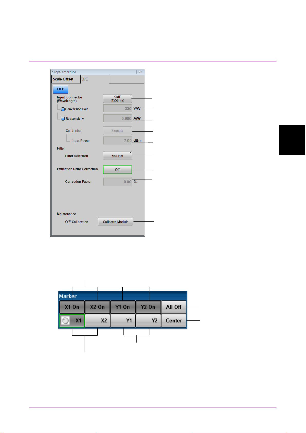
3.2 Correspondence Between Panel and Messages
Message List
:INPut:WAVLength
:CALibrate:CGain
:CALibrate:RESPonsivity
:CALibrate:AUTocorrect
:CALibrate:CALPower
:FILTer
:CONFigure:EXRCorrection
:CONFigure:EXRCorrection:FACTor
:CALibrate:OEPower[:JUDGe]
:CALCulate:MARKer:AOFF
:CALCulate:MARKer:CENTer
:CALCulate:MARKer:LOCation:{CHA|CHB|CHC|CHD}:{Y1|Y2}
:CALCulate:MARKer:LOCation:{X1|X2}
:CALCulate:MARKer:{X1|X2|Y1|Y2}
Figure 3.2.5.5-3 Messages Corresponding to Amplitude Dialog Box (MP2110A) (O/E)
3.2.5.6 Marker
3
Figure 3.2.5.6-1 Messages Corresponding to Marker Dialog Box
3-39
Page 96

:HISTogram:CENTer
:CONFigure:HISTogram:AXIS
:HISTogram:{Y1|Y2}
:HISTogram:{X1|X2}
:CONFigure:HISTogram
Chapter 3 Message List
3.2.5.7 Histogram
Figure 3.2.5.7-1 Messages Corresponding to Histogram Dialog Box (MP2110A)
3-40
Page 97

3.2 Correspondence Between Panel and Messages
Message List
*OPT?
*IDN?
*OPT?
*IDN?
3.2.6 Messages corresponding to Information
3
Figure 3.2.6-1 Messages Corresponding to Information Dialog Box from Setup Utility
(MP210xA, MP2100B)
Figure 3.2.6-2 Messages Corresponding to System Information Dialog Box from System
Menu (MP2110A)
3-41
Page 98

:SYSTem:DISPlay:DATA?
Queries the data of the screenshot image file.
:SYSTem:DISPlay:RESult
Sets and queries the On/Off state of the
plotting processing of measurement results.
TRM
Sets and queries the terminator of response
data.
GTL
Added in Version 5
: Changes the status to
Local.
:SYSTem:VERSion?
Queries the version of SCPI.
:TIME:TRACking:STATus?
Queries the tracking status of Scope.
:TRACe:{CHANnelA|CHANnelB|CHANnelC|CHANne
lD|CHANnels}?
Queries the trace data of Scope.
Chapter 3 Message List
3.2.7 Messages with no corresponding panel operation
Command messages with no corresponding panel operation are listed
below.
For messages corresponding to the status registers, refer to 2.8.4
“Operation Status Register” and 2.8.5 “Device Dependent Registers”.
Table 3.2.7-1 Messages with No Corresponding Panel Operation (SCPI)
Command Details
3-42
Page 99

3.3 Messages Corresponding to Common Operations
Message List
3.3 Messages Corresponding to Common Operations
3.3.1 Setting system configuration
TRM
Function
This command sets and queries the type of terminator of the response
data.
Syntax
{TRM|:SYSTem:TERMination} 0|1
{TRM|:SYSTem:TERMination}?
Parameter
0 LF+EOI (default)
1 CR+LF+EOI
LF (Line Feed) is 0x0A in ASCII.
CR (Carriage Return) is 0x0D in ASCII.
EOI (End or Identify) is a GPIB interface signal indicating the end of
data.
Response Data
0|1
Example of Use
To set the terminator type to LF+EOI:
TRM 0
TRM?
>TRM 0
GTL (Go to local)
Function
Added in Version 5:
and changes the status to Local.
Example of Use
GTL
This command releases the remote connection status
3
3-43
Page 100

Chapter 3 Message List
:SYSTem:BEEPer:SET
Function
Only in MP210xA and MP2100B:
buzzer ON/OFF.
Syntax
:SYSTem:BEEPer:SET <enable>
:SYSTem:BEEPer:SET?
Parameter
0|OFF
1|ON
Response Data
0|1
Example of Use
To set buzzer ON:
:SYST:BEEP:SET ON
:SYST:BEEP:SET?
>1
Note:
When this command is used in MP2110A, an error (–113 Undefined
Header) occurs because MP2110A does not support this command.
This command sets and queries the
3-44
 Loading...