

Anritsu HFE0503 Kurzrok

60 High Frequency Electronics
High Frequency Design
TEST ACCESSORIES
Simple Lab-Built Test
Accessories for RF, IF,
Baseband and Audio
By Richard Kurzrok
RMK Consultants
E
very engineering
lab bench needs a
supply of handy
test accessories—cables,
adapters, attenuators,
couplers, combiners, filters, detectors, limiters,
etc. This article describes
several accessories that
can be built quickly (and cheaply), yet they
provide sufficient performance from DC to 100
MHz. This frequency range includes most
audio, baseband and intermediate frequency
circuits, as well as many RF applications from
VLF through VHF.
Connector-Mounted Accessories
Low cost tests pieces can be realized using
BNC panel jacks and associated hardware,
although improvements can be attained using
UHF connectors and panel jacks, as well as
the higher quality N and TNC connectors.
SMA and similar microwave connectors can
certainly be used, but most hand-built circuits
will not require their microwave performance.
Low cost test pieces can be constructed
readily, via machine screw and solder assembly, using four hole coaxial panel jacks without
printed circuit boards or enclosures. This technique has been demonstrated for passive circuits using BNC connectors [1], and UHF connectors have been extensively used with low
cost transmission line transformers [2].
Connector Performance
Some coaxial panel jack characteristics
are shown in Table 1. With BNC hole spacing
of 0.500 inch and #4-40 screws, the working
cross section area of BNC and TNC connectors
is 0.500 – 0.125 = 0.375 inch. The corresponding working cross section of N and UHF connectors is 0.718 – 0.138 = 0.580 inch. The additional area can permit construction of test
pieces with larger components such as half
inch diameter toroidal inductors.
Typical small quantity unit costs for commercial grade coaxial connectors from economical distributors are $1.25 for BNC panel
jacks, $2.50 for TNC panel jacks, $2.50 for N
panel jacks and $0.65 to $1.00 for UHF panel
Here are some practical
tips for making simple test
accessories to use at your
engineering workbench:
filters, detectors, attenua-
tors and return loss bridges
for audio and RF/IF
Connector Flange Size Hole C/L Hole Dia. Peak Volts Max. Freq.
BNC .687 or .750 .500 or .531 .125 500 4 GHz
TNC .687 .500 .125 500 11 GHz
N 1.000 .718 .125 1,500 11 GHz
UHF 1.000 .718 .125 or .138 500 300 MHz
Notes: 1. BNC, TNC, and N connectors have 50 ohm impedance. UHF impedance is not specified.
2. Flange is square with rounded corners. Dimensions are in inches.
3. 0.125 holes provide clearance for #4-40 screws; 0.138 holes are for #6-32.
4. Some BNC and TNC connectors are tapped for #3-48 instead of 0.125 diameter. These holes must
be drilled if larger hardware is desired.
Table 1 · Mechanical and electrical characteristics of common coaxial connectors.
From May 2003 High Frequency Electronics
Copyright © 2003 Summit Technical Media, LLC
62 High Frequency Electronics
High Frequency Design
TEST ACCESSORIES
jacks, depending on quality and manufacturer. Quantity discounts have
not been considered. Since UHF connectors have the lowest unit cost and
are readily available, this article will
emphasize low cost test pieces using
UHF connectors. These costs will
change with time, and higher prices
will be paid for military grade connectors, different quality commercial
connectors, and for retail purchase.
UHF Panel Jack Performance
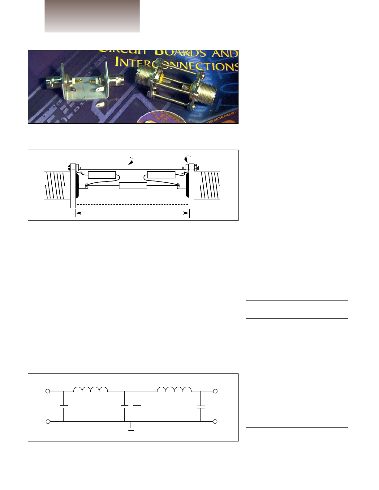
Figure 1 is a photo that shows two
UHF connectors in a mounting that
allows various circuits to be con-
structed with components supported
by their leads. Also in this photo is an
assembly of two BNC jacks mounted
to a U-shaped bracket, which allows
similar circuit assembly using these
connectors.
The upper frequency limit for
UHF connectors is 300 MHz and the
impedance is not specified. To evaluate these connectors, a preliminary
50 ohm test piece was constructed
using two UHF panel jacks interconnected back-to-back with no special
concern for impedance matching.
Insertion losses were less than 0.1 dB
up to 90 MHz.
Practical Test Circuits
A pi-section fixed pad attenuator,
using two UHF panel jacks and associated hardware, is illustrated in
Figure 2. This simple circuit is displayed mainly for illustrative purposes—resistive pads are readily available and inexpensive, but custom
attenuators with non-standard values can be made in this manner.
Another test piece with two UHF
jacks separated by two inch long #632 screws was constructed and tested. This unit is a five pole low pass filter with nominal 0.02 dB passband
ripples, three dB cutoff of 2.2 MHz,
and 50 ohm impedance. The filter
schematic is shown in Figure 3. All
shunt capacitors are polypropylene
units with two percent tolerance. The
series inductors use 34 turns of #26
magnet wire on MicroMetals T50-2
toroids, which have a nominal 0.5
inch outside diameter. Measured test
data is shown in Table 2.
Other Useful Circuits
As we have seen, low cost 50 ohm
test pieces operating at typical frequencies from 100 kHz to 100 MHz
can be readily constructed using
UHF panel jacks and other connectors, soldered components, hand
Frequency Insertion Loss
(MHz) (dB)
0.3 <0.1
0.7 <0.1
1.0 0.1
1.3 0.2
1.6 0.3
1.8 0.4
2.0 1.1
2.2 3.5
2.4 7.2
2.9 18.0
3.5 27.0
4.0 34.3
10.0 >40
20.0 >40
Table 2 · Measured amplitude
response for the 2.2 MHz lowpass filter mounted on UHF connectors.
Figure 1 · Back-to-back mounting of low-cost coaxial connectors allows
easy construction of test circuits.
Figure 2 · Assembly diagram of a simple UHF connector-based pi-section
attenuator (not to scale).
Figure 3 · Circuit diagram of a 2.2 MHz lowpass filter.
R1
R3
R2
L2 – 6.02 µH
C1
1,500 pF
C4
1,500 pF
C3
1,500 pF
C6
1,500 pF
L5 – 6.02 µH
1-3/16 inch typical with 1-1/2 in. screws
Solder lugs
#4-40 or 6-32 screws, lockwashers, nuts
 Loading...