


CP-5000
Electronic Time Recorder
User’s Guide

Proprietary Notice
This document contains proprietary information and such information may not be reproduced in whole or part without the written permission from Amano Cincinnati, Inc. 140 Harrison Ave., Roseland, New Jersey 07068.
Amano Cincinnati, Inc. reserves the right to make equipment changes and improvements which may not be reflected in this document. Portions of this document may have been updated to include the latest hardware or firmware version, if applicable.
To ensure safe use of this time recorder/stamp, be sure to thoroughly read this manual in its entirety before any attempt is made to operate the equipment. After you have finished reading this manual, be sure to store it and in a safe place for further reference.
Thank You…
For purchasing another fine product from
Amano Cincinnati, Inc.

|
Table of Contents |
Chapter 1: Introduction.......................................................................... |
1-1 |
Specifications ....................................................................................... |
1-1 |
Accessories.......................................................................................... |
1-2 |
Names and Functions of Parts ............................................................. |
1-3 |
Front Panel Description........................................................................ |
1-3 |
Chapter 2: Getting Started..................................................................... |
2-1 |
Top Cover ............................................................................................ |
2-1 |
Front Cover .......................................................................................... |
2-2 |
Removal ............................................................................................ |
2-2 |
Installation ......................................................................................... |
2-2 |
Placement/Location.............................................................................. |
2-3 |
Desktop Installation ........................................................................... |
2-3 |
Wall Mounting.................................................................................... |
2-4 |
External Signal Connections ................................................................ |
2-6 |
Optional Accessory Battery Pack (ATR-20095x).................................. |
2-8 |
Installation ......................................................................................... |
2-8 |
Power Connection................................................................................ |
2-9 |
Initialization and Reset ......................................................................... |
2-10 |
Reset Button...................................................................................... |
2-10 |
Initialization (All Clear)....................................................................... |
2-10 |
Chapter 3: Time Cards ........................................................................... |
3-1 |
Making a Test Print .............................................................................. |
3-1 |
Chapter 4: Programming ....................................................................... |
4-1 |
Introduction .......................................................................................... |
4-1 |
General Programming Guidelines ........................................................ |
4-1 |
Entering Program Mode .................................................................... |
4-1 |
Entering and Saving Values .............................................................. |
4-2 |
Scrolling Through the Program Mode................................................ |
4-2 |
Exiting Program Mode....................................................................... |
4-2 |
Programming Guide .......................................................................... |
4-3 |
Basic Programming.............................................................................. |
4-6 |
Programming Password (Menu 3)..................................................... |
4-6 |
Year, Month, and Date (Menu 1, Items 1 & 2)................................... |
4-6 |
Hours and Minutes (Menu 1, Item 3) ................................................. |
4-8 |
Daylight Savings Time (DST) (Menu 2)................................................ |
4-9 |
Automatic Adjustment Settings.......................................................... |
4-9 |
Programming DST (Menu 2, Items 1 – 3).......................................... |
4-10 |
Disabling DST ................................................................................... |
4-11 |
Hours Display and Imprint (Menu 4, Items 1 – 7) ................................. |
4-12 |
Index Number Imprint (Menu 4, Item 8)................................................ |
4-14 |
Signal Duration (Menu 5, Item 1) ......................................................... |
4-14 |
Weekly Programming (Items 01 – 80).................................................. |
4-15 |
Functions Available in Weekly Programming .................................... |
4-15 |
Creating a Weekly Program .............................................................. |
4-16 |
CP-5000 User’s Guide |
i |

Obtaining a Printout of Programmed Data (Menu 7)............................. |
4-18 |
Editing Weekly Programs ..................................................................... |
4-19 |
Adding Additional Weekly Programs..................................................... |
4-19 |
Deleting a Weekly Program .................................................................. |
4-20 |
Chapter 5: Maintenance.......................................................................... |
5-1 |
Service.................................................................................................. |
5-1 |
Exterior ................................................................................................. |
5-1 |
Ribbon Replacement ............................................................................ |
5-1 |
Time/Date Memory Backup Battery...................................................... |
5-3 |
Chapter 6: Troubleshooting ................................................................... |
6-1 |
Introduction........................................................................................... |
6-1 |
General Problems................................................................................. |
6-1 |
Signal................................................................................................. |
6-1 |
Foreign Object or Material ................................................................. |
6-2 |
Programming ..................................................................................... |
6-2 |
Key Failure......................................................................................... |
6-2 |
Audible Beeps.................................................................................... |
6-2 |
Error Messages .................................................................................... |
6-3 |
Err 1 thru Err 9 ................................................................................... |
6-3 |
Display Related Problems .................................................................... |
6-7 |
Low Battery........................................................................................ |
6-7 |
Power Failure..................................................................................... |
6-7 |
Inaccurate Clock ................................................................................ |
6-7 |
LED’s Not Functioning .......................................................................... |
6-7 |
Hour Change ........................................................................................ |
6-8 |
Card Feed Problems............................................................................. |
6-8 |
Card Refused..................................................................................... |
6-8 |
Card Cannot Enter or Card Blocked .................................................. |
6-8 |
Card Refused, Date and Time in Display........................................... |
6-9 |
Imprint Problems................................................................................... |
6-9 |
Overprint ............................................................................................ |
6-9 |
Imprint Position Wrong....................................................................... |
6-9 |
Wrong Color Printed .......................................................................... |
6-10 |
Weak or Light Printing ....................................................................... |
6-10 |
Diagnostics (Menu 8)............................................................................ |
6-11 |
LED Test (Menu 8, Item 1)................................................................. |
6-11 |
Mode and Keys Test (Menu 8, Item 2)............................................... |
6-12 |
LCD Test (Menu 8, Item 3) ................................................................ |
6-13 |
EPROM (Memory) Test (Menu 8, Item 4) .......................................... |
6-13 |
Buzzer Test (Menu 8, Item 5) ........................................................... |
6-14 |
Signal Test (Menu 8, Item 6).............................................................. |
6-15 |
Motor Test (Menu 8, Item 7) .............................................................. |
6-15 |
Firmware Version Number (Menu 8, Item 8)...................................... |
6-16 |
Print Counter (Menu 8, Item 9) .......................................................... |
6-16 |
Card Print Test (Menu 8, Item 10) ..................................................... |
6-16 |
Chapter 7: Appendix............................................................................... |
7-1 |
ii |
CP-5000 User’s Guide |

Chapter 1: Introduction
Before attempting to use the Amano CP-5000 time recorder/stamp, please carefully review Chapter 1: “Introduction”, Chapter 2: “Getting Started”, Chapter 3: “Time Cards”, and Chapter 4: “Programming”. This chapter of the manual covers the specifications, accessories, names and functions of parts, LCD Display, and description of controls.
Specifications
Power Requirements: |
120 VAC ± 10%, 50/60 Hz |
Power Consumption: |
6 W Idle, 60W maximum |
Ambient Temperature: |
32°F to 113°F (0°C to 45°C) |
Ambient Humidity: |
10% to 90% (non-condensing) |
Dimensions: |
12.3” (313 mm) High X 10.2" (259 mm) Wide X 6.1" (155 mm) |
|
Deep. |
Weight: |
Approximately 9.00 lbs. (4.1 kg) |
Environment: |
Indoor use only; dust-free environment. Keep out of direct |
|
sunlight. |
Mounting: |
Wall or Table Mount |
|
|
Time Card: |
Amano Time Cards |
|
Amano Part Number: C-3000 Time Cards |
|
3.36 ± .016” (85.4 ±.4mm) (W) x 8.27” (210mm) (H) 150 lb. |
|
Manila card (.0126” (0.32mm) thick) |
Ribbon: |
Two-color cartridge |
|
Amano Part Number: CE-316452 |
CP-5000 User’s Guide |
1-1 |
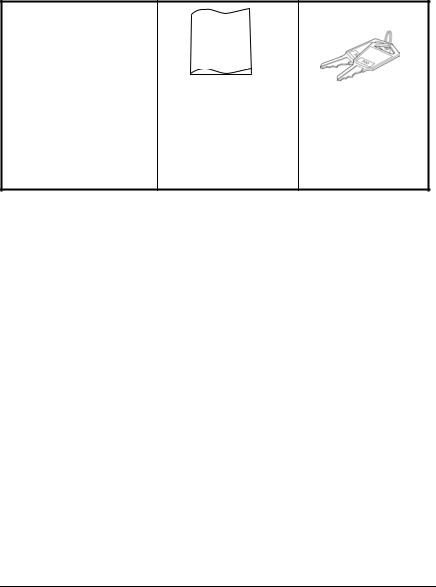
Accessories
The following accessories are provided with the Amano CP-5000. After unpacking, please ensure that all of the following items are provided:
User’s
Guide
CP-5000 |
This User’s Guide |
Keys |
(1 unit) |
(1 copy) |
(one pair, 2 keys) |
•Please note that specifications, appearance, and/or description are subject to change without notice due to product enhancements.
•This user’s guide has been carefully prepared, but Amano assumes no liability for errors and/or omissions. If you should find any errors or unclear information, please contact your Amano dealer.
1-2 |
CP-5000 User’s Guide |

Names and Functions of Parts
The following describes the names and functions of various parts of the CP-5000.
External View
Front Panel Description
The front panel displays the date, time, day of the week, and is used for programming the unit. It is accessed by removing the top cover. (see Chapter 2: “Getting Started” for more details).
CP-5000 User’s Guide |
1-3 |

Component |
Name |
Normal Mode |
Program/Ink Mode |
|
LED Indicator |
Day of the week |
Current menu in display |
|
|
|
|
|
Mode Switch |
Normal Operation |
Enter Program/Ink Ribbon |
|
|
|
replacement mode |
|
|
|
|
|
Function Key |
Not Available |
Move to the next menu |
|
|
|
|
|
Enter Key |
Not Available |
Accept data in the display, and |
|
|
|
move to the next item in the |
|
|
|
current menu or next menu. |
|
Change Key |
Not Available |
Edit data in the display. Pressing |
|
|
|
this key will increment the |
|
|
|
displayed value by one. Holding |
|
|
|
the key down for more than three |
|
|
|
seconds will increment the |
|
|
|
displayed value by ten. |
Note: ESD (Electrostatic Discharge) precautions should be observed before removing the top cover.
1-4 |
CP-5000 User’s Guide |

Chapter 2: Getting Started
Before using the Amano CP-5000 time recorder/stamp, please carefully review this chapter of the manual, which covers:
•Top cover removal and installation
•Front cover removal and installation
•Placement/Location
•Desktop Installation
•Wall Mounting
•External Signal Connections
•Battery Connection
•Initialization and Reset
•Power Connection
Top Cover
The top cover must be removed to configure, install, and program the CP-5000. To remove the top cover, follow these steps:
1.Insert the key provided in the keyhole, and turn the key clockwise to unlock the cover. The top cover should “pop” open.
2.Pivot the top cover upwards, and lift the cover to remove.
3.To re-install the top cover, set and align it with the groves on the housing, then press it into place until it clicks.
CP-5000 User’s Guide |
2-1 |

Front Cover
Removal
The front cover must be removed to connect the Full Power Reserve Battery and connect the external signal line for the CP-5000. To do so, perform the following steps:
1.Disconnect the power cord from the power source if applicable.
2.Remove the top cover.
3.Lay the unit face up on a flat surface.
4.Facing the front of the unit, remove the two Phillips head screws in the upper corners of the housing.
5.Press both of your hands flat against the sides of the front cover.
6.Pivot the front cover towards you. Support the front cover so that it doesn’t stress the ground wire connections. Set face up on a flat surface.
Installation
1.With the front cover on a flat surface and facing up, press both of your hands flat against the sides.
2.Facing the bottom of the unit, set and align the tabs on the bottom of the front cover with the grooves on the housing.
3.Pivot the front cover towards the housing. Reconnect the ground wire, push the cover down in place and secure it with the two Phillips head screws.
4.Reinstall the top cover. Reconnect the power cord to the power source.
2-2 |
CP-5000 User’s Guide |
Placement/Location
When choosing a mounting location for your CP-5000, you should ensure the following parameters are met:
•The mounting surface and hardware is capable of supporting the unit’s weight, approximately 10 lbs., or 4.54 kg.
•The area must be within the specified operating temperature range (see page 1-1).
•The unit has access to a power source (AC wall outlet).
•The area can accommodate signal and/or power conduits.
•The following conditions do not exist:
Desktop Installation
Place the time recorder on a level surface. The recommended height of the surface should be 29½” (75 cm) from the floor.
CP-5000 User’s Guide |
2-3 |

Wall Mounting
For proper wall mounting, follow these steps:
1.Disconnect the power cord from the power source.
2.Unlock and remove the top cover.
3.Remove the two screws on the top and slide the back plate downward to remove it. Set the CP-5000 face up on a flat surface.
Note: The right side back plate screw also secures a ground wire.
4.Using a punch, knock out the center material from the teardropshaped mounting hole on the back plate.
5.Using the back plate as a template, approximate the final location of the clock, and mark the location of the teardrop mounting hole on the wall.
6.Hang the back plate on a screw or anchor from the teardrop-shaped mounting hole.
7.Level the back plate and mark the location of the bottom two mounting holes.
8.Secure the back plate to the wall by inserting screws through the bottom two mounting holes.
9.Holding the sides of the cover, lift the CP-5000, bottom forward, to the back plate.
10.Align the tabs on the bottom of the CP-5000 housing with the grooves in the bottom flange of the back plate. Hold the CP-5000 in place so that the tabs are even with the bottom flange. Do not rest the unit on the flange.
2-4 |
CP-5000 User’s Guide |

11.Carefully pivot the CP-5000 away from you onto the back plate until its side hooks fit in the slots on the back of the unit. The upper flange of the back plate should be aligned with the slot in the top of housing.
12.Install the two screws that secure the back plate to the unit. Make sure you re-install the ground wire.
13.If you need to connect external signal wiring, or connect the battery, do not replace the top cover or reconnect the power cord at this time.
CP-5000 User’s Guide |
2-5 |

External Signal Connections
The CP-5000 is equipped with a single external signal relay circuit that enables you to activate an audible device such as a bell or buzzer. The relay contacts of the circuit are Normally Open and should not exceed Class 2 Circuit requirements (24 VDC at 1A). The duration (in seconds) that the relay contacts will be activated or closed is set in the Signal Duration menu item, and the time of the day and day of the week that this will occur on is set in the Weekly Programming menu.
The wiring schematic for the external signal relay circuit is as follows:
Note: This procedure must be performed with power to both the external device and the CP-5000 disconnected.
To connect a device to the relay signal circuit, perform the following steps:
1.Make sure that power to both the external device and the CP-5000 are disconnected.
2.Following the manufacturer’s guidelines for the external device, connect the signal wires to it and run them to the mounting location of the CP-5000. Make sure the wires are properly labeled.
2-6 |
CP-5000 User’s Guide |
3.Strip approximately .25” (6 mm) of insulation off the ends of the wires that will be connected to the CP-5000.
4.Remove the top cover from the CP-5000.
5.Remove the front cover; support the cover so that it doesn’t hang from the ground wire.
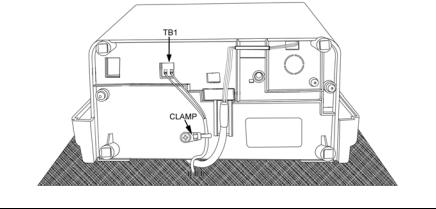
6.With the unit flat and face up, locate terminal block TB1.
7.Using a small-blade screwdriver, loosen the screws on the TB1 side of the connector block.
8.Observing polarity, insert one wire into the CP-5000 through the open hole and connect it to the proper terminal position of TB1. Using a screwdriver, secure the wire in place. Insert the other wire into the unit and secure in place. Make sure that only the stripped wire is clamped, and not the insulation.
9.Check the connections by tugging on each wire. If they appear loose, repeat the previous step.
10.Clamp the signal wires as shown in the following drawing using a cable clamp appropriate to your cable thickness.
CP-5000 User’s Guide |
2-7 |
Optional Accessory Battery Pack (ATR-20095x)
Installing the Full Power Reserve Battery (available as a kit: P/N ATR20095x) will allow the CP-5000 to maintain normal operations for 12 hours or 300 punches in the event of an AC power failure.
Installation
Note: This procedure must be performed with the power cord disconnected from the power source.
To install the Full Power Reserve Battery perform the following steps:
1.Remove the top cover.
2.Remove the front cover.
3.Remove the back plate.
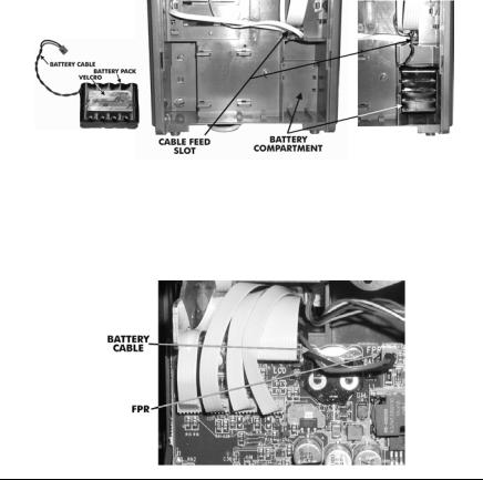
4.Remove the backing paper from the Velcro.
5.Slide the battery pack into the compartment and press firmly into place to allow the adhesive on the Velcro fastener to hold.
6.Feed the battery cable through the cable feed slot at the top of the battery compartment and over the top of the PC board.
7.Connect the battery cable to FPR on the PC Board.
2-8 |
CP-5000 User’s Guide |

Note: The battery will not power the clock until after the clock is initially plugged in. Afterwards, power will automatically be supplied by the battery in the event of an AC power failure.
8.Replace the back plate
9.Replace the front cover.
10.Replace the top cover.
Note: To insure premium performance it is recommended that the battery be fully charged prior to use (approximately 24 hours).
Note: To avoid damaging the battery, or draining it to an unrecoverable level, keep the machine plugged into an AC power source during normal operation. The power reserve battery is intended to be used for limited power outages, not as a power source during normal operations.
Power Connection
AC Power connections are made by plugging the power cord into a suitable, grounded outlet.
CP-5000 User’s Guide |
2-9 |
Initialization and Reset
Prior to first use, the CP-5000 must be initialized to clear any possible unexpected program parameters. Initialization (All Clear) erases all user programming and resets the time and date to their default settings.
Reset Button
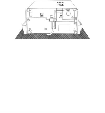
The Reset button can be pressed if the clock becomes unresponsive. This has the same effect as cycling the power, and will not change the time and date or erase any programming.
Insert a small screwdriver into the Reset Hole on the bottom of the unit and press the Reset button.
Initialization (All Clear)
This function is provided to clear all programmed settings (weekly programs, imprint formatting, etc.) from the CP-5000. When used, all programming (including time, date and password) will be erased and the unit will be returned to its default settings. You should only initialize your CP-5000 prior to programming a new unit or when instructed to in the Troubleshooting section of this manual.
Note: ESD (Electrostatic Discharge) precautions should be adhered to when removing the top cover.
2-10 |
CP-5000 User’s Guide |
Initialize your CP-5000 as follows:
1.Remove the top cover. Set the Mode Switch to Program/Ink Mode.
2.Insert a small screwdriver into the Reset Hole on the bottom of the unit and press and hold the Reset button.
3.While holding the Reset button, simultaneously press and hold the Enter key and the Change key.
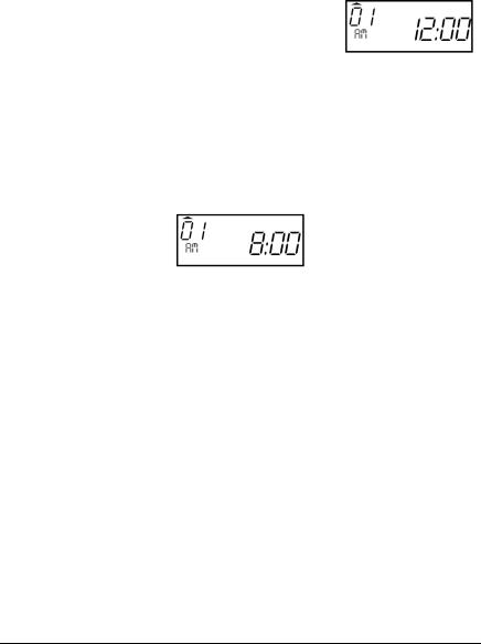
4.Release the Reset button; continue to hold the Enter key and the Change key until five rapid beeps sound, indicating a successful reset to all default settings (showing a time of
12:00 AM on January 1, 2007). After a few moments, the clock will return to its Enter Password mode.
5.Enter the default password (0000) and reprogram the unit as desired. Set the Mode Switch to Normal and reinstall the top cover.
When the AC power is properly connected, the LED will cease to flash and the LCD display will show normal time indication in the (12 hour) format:
Note: If using the Full Power Reserve Battery, to insure premium performance, it is recommended that the battery be fully charged prior to use (approximately 24 hours).
Note: If using the Full Power Reserve Battery, to avoid damaging the battery or draining it to an unrecoverable level, keep the machine plugged into an AC power source during normal operation. The Full Power Reserve Battery is intended for limited power outage usage, and not as a power source during normal operations.
CP-5000 User’s Guide |
2-11 |

This page intentionally left blank.
2-12 |
CP-5000 User’s Guide |
Chapter 3: Time Cards
Making a Test Print
Follow these steps to make a test print:
1.Make sure that there is power to the CP-5000, and that the top cover is in place.
2.Gently insert a time card into the card throat. The card will automatically be fed in, printed and ejected. Do not force it in or attempt to pull it out before it has been ejected.
3.As shipped, the CP-5000 is configured to print in the following format:
4.If this imprint is acceptable, the CP-5000 is ready to be programmed for use (time and date). If you wish to change the style of the imprint, you must program an imprint style for your application in addition to setting the time and date for your CP-5000. Please refer to the Basic Programming section of Chapter 4 to set year, time, and date imprints.
CP-5000 User’s Guide |
3-1 |
 Loading...