


ARUF29B14
Amana ARUF29B14, ARUF37C14, ARUF25B14, ARUF43C14, ARUF43D14 Installation & Operating Instructions Manual
...
ARUF**14** / ASPT**14**
AIR HANDLERS INSTALLATION & OPERATING INSTRUCTIONS
Contents
1 Important Safety Instructions...................................1
2 Shipping Inspection ...............................................3
2.1 Parts .......................................................... 3
2.2 Handling ...................................................... 3
3 Codes & Regulations .............................................. 3
4 Replacement Parts ................................................ 3
5 Pre-Installation Considerations ................................3
5.1 Preparation .................................................. 3
5.2 System Matches ............................................. 3
5.3 Interconnecting Tubing..................................... 3
5.4 Clearances ................................................... 4
5.5 Horizontal Applications .................................... 4
6 Installation Location ............................................. 4
6.1 Upflow Installation ......................................... 4
6.2 Horizontal Left Installation ............................... 4
6.3 Downflow..................................................... 4
6.4 Horizontal Right Installation.............................. 5
7 Refrigerant Lines ..................................................7
7.1 Tubing Size ................................................... 7
7.2 Tubing Preparation ......................................... 7
7.3 Special Instructions......................................... 7
7.4 Tubing Connections for Flowrator Model ............... 7
7.5 Tubing Connections for TXV Models ...................... 8
8 Condensate Drain Lines ..........................................8
9 Ductwork............................................................ 9
9.1 Return Ductwork ............................................ 9
10 Return Air Filters ................................................ 9
11 Electric Heat...................................................... 9
12 Electrical and Control Wiring ............................... 11
12.1 Building Electrical Service Inspection................ 11
12.2 Wire Sizing ............................................... 11
12.3 Maximum Overcurrent Protection (MOP) ............ 11
12.4 Electrical Connections – Supply Voltage ............. 12
12.4.1 Air Handler Only (Non-Heat Kit Models) .....12
12.4.2 Air Handler - Non-Circuit Breaker Heat Kits......12
12.4.3 Air Handler With Circuit Breaker Heat Kit........12
12.5 Low Voltage Connections............................... 12
12.5.1 Thermostats .......................................... 12
12.6 Speed Tap Adjustment.................................. 12
13 Achieving 1.4% Low Leakage Rate ......................... 13
14 Start-Up Procedure............................................ 13
15 Regular Maintenance.......................................... 13
16 Airflow Data .................................................... 14
21 Wiring Diagrams................................................ 20
1 Important Safety Instructions
The following symbols and labels are used throughout this
manual to indicate immediate or potential safety hazards.
It is the owner’s and installer’s responsibility to read and
comply with all safety information and instructions accompanying these symbols. Failure to heed safety information
increases the risk of personal injury, property damage, and/
or product damage.
RECOGNIZE THIS SYMBOL
AS A SAFETY PRECAUTION.
Keep this literature in a safe place for future reference.
ATTENTION INSTALLING PERSONNEL
IO-901
2/2015
It is your responsibility to install the product safely and to educate the customer on its safe use.
Prior to installation, thoroughly familiarize yourself with this Installation Manual.
Observe all safety warnings. During installation or repair, caution is to be observed.

HIGH VOLTAGE!
Disconnect ALL power before ser vicing.
Multiple power sources may be present.
Failure to do so may cause p roperty damage,
personal injury or death.
Install ati on an d re pair of t his u ni t sho uld b e p erf orm ed
by indiv id uals me et ing t he requi re men ts of an
ONLY
“entry level technician” as specified by
, at a minimum,
the Ai r-Co ndi ti on in g, H eati ng a nd Re fri g erati on I nst i tu te
(AHRI). Attempting to install or repair this unit without
such ba ck grou nd may re sul t i n p r od uct damag e,
personal inju ry or death.
This product is factory-shipped for use with
208/240/1/60 electrical power supply.
DO NOT
reconfigure this air handler to operate with any other
power supply.
To avoid property damage, personal injury or death
due to electrical shock, this unit MUST have an
uninterrupted, unbroken
electrical ground. The
electrical ground circuit may consist of an
appropriately sized electrical wire connecting the
ground lug in the unit control box to the building
electrical service panel.
Other meth ods of gro unding ar e p ermit te d i f pe rfo rmed
in accordance with the National Electric Code
(NEC) /Amer ican National Stan dards I nsti tute
(ANSI)/ Nati onal Fire P rotec tion A ssocia tion (NFP A) 70
and local /s ta te c ode s. I n Canada, e le ctr ica l gro undi ng
is to be in accordance wit h the C ana dian Electric Code
(CSA) C22.1.
When installing or servicing this equipment, safety
clothing, including hand and eye protection, is
strongly recommended. If installing in an area that has
special safety requirements (hard hats, etc.), bserve
o
these requirements.
Do not connect to or use any device that is not designcertified by the manufacturer for use with this unit.
Serious property damage, personal injury, reduced
unit performance and/or hazardous conditions may
result from the use of such non-approved devices.
To prevent the risk of property damage, personal
injury , or dea th, do not store comb ustible m aterials or
use gasoline or other flammable liquids or vapors in
the vicin ity of this unit.
CO can ca u se serious il lness includ in g permanent b r ai n
damage or death.
Advertencia especial para la instalación de calentadores ó manejadoras
de aire en áreas cerradas como estacionamientos ó cuartos de servicio.
Las emisiones de monóxido de carbono pueden circular a través
del aparato cuando se o pe ra en cua lqu i e r mo do .
El mo nó xido de carbo no puede ca usar enferme da des severas
como daño cerebral permanente ó muerte.
RISQUE D'EMPOISONNEME NT AU
Cette ven t ilation est nécess aire po ur éviter le danger d'intoxicati on
au CO pouvant survenir si un appareil produisant du monoxyde
de carbone contin ue de fonctionner au sein d e la zone confinée.
MONOXYDE DE CARBONE
2

2 Shipping Inspection
Always transport the unit upright; laying the unit on its side or top during transit may cause equipment damage. The
installer should inspect the product upon receipt for shipping damage and subsequent investigation is the responsibility of
the carrier. The installer must verify the model number, specifications, electrical characteristics, and accessories are
correct prior to installation. The distributor or manufacturer will not accept claims from dealers for transportation
damage or installation of incorrectly shipped units.
2.1 Parts
Also inspect the unit to verify all required components are present and intact. Report any missing components
immediately to the manufacturer or to the distributor. Use only factory authorized replacement parts (see Section
5). Make sure to include the full product model number and serial number when reporting and/or obtaining service
parts.
2.2 Handling
Use caution when transporting/carrying the unit. Do not move unit using shipping straps. Do not carry unit with hooks
or sharp objects. The preferred method of carrying the unit after arrival at the job site is to carry via a two-wheel
hand truck from the back or sides or via hand by carrying at the cabinet corners.
3 Codes & Regulations
This product is designed and manufactured to comply with applicable national codes. Installation in accordance with such
codes and/or prevailing local codes/regulations is the responsibility of the installer. The manufacturer assumes no
responsibility for equipment installed in violation of any codes or regulations.
The United States Environmental Protection Agency (EPA) has issued various regulations regarding the introduction
and disposal of refrigerants. Failure to follow these regulations may harm the environment and can lead to the
imposition of substantial fines. Should you have any questions please contact the local office of the EPA and/or refer to
EPA’s website www.epa.gov.
4 Replacement Parts
When reporting shortages or damages, or ordering repair parts, give the complete product model and serial numbers as
stamped on the product. Replacement parts for this product are available through your contractor or local distributor.
For the location of your nearest distributor consult the white business pages, the yellow page section of the local telephone book or contact:
CONSUMER AFFAIRS
GOODMAN MANUFACTURING COMPANY, L.P.
7401 SECURITY WAY
HOUSTON, TEXAS 77040
(877) 254-4729
5 Pre-Installation Considerations
5.1 Preparation
Keep this document with the unit. Carefully read all instructions for the installation prior to installing product. Make
sure each step or procedure is understood and any special considerations are taken into account before starting
installation. Assemble all tools, hardware and supplies needed to complete the installation. Some items may need to
be purchased locally. Make sure everything needed to install the product is on hand before starting.
5.2 System Matches
The entire system (combination of indoor and outdoor sections) must be manufacturer approved and Air-Conditioning, Heating, and Refrigeration Institute (AHRI) listed. NOTE: Installation of unmatched systems is not permitted and
will void the product warranty.
5.3 Interconnecting Tubing
Give special consideration to minimize the length of refrigerant tubing when installing air handlers. Refer to Remote
Cooling/Heat Pump Service Manual RS6200006, and TP-107 Long Line Set Application R-410A for tubing guidelines. If
possible, allow adequate length of tubing such that the coil may be removed (for inspection or cleaning services) from
the cabinet without disconnecting the tubing.
3

5.4 Clearances
The unit clearance from a combustible surface may be 0". However, service clearance must take precedence. A
minimum of 24" in front of the unit for service clearance is required. Additional clearance on one side or top will be
required for electrical wiring connections. Consult all appropriate regulatory codes prior to determining final clearances. When installing this unit in an area that may become wet (such as crawl spaces), elevate the unit with a
sturdy, non-porous material. In installations that may lead to physical damage (i.e. a garage) it is advised to install
a protective barrier to prevent such damage. Always install units such that a positive slope in condensate line (1/4"
per foot) is allowed.
5.5 Horizontal Applications
If installed above a finished living space, a secondary drain pan (as required by many building codes), must be
installed under the entire unit and its condensate drain line must be routed to a location such that the user will see
the condensate discharge.
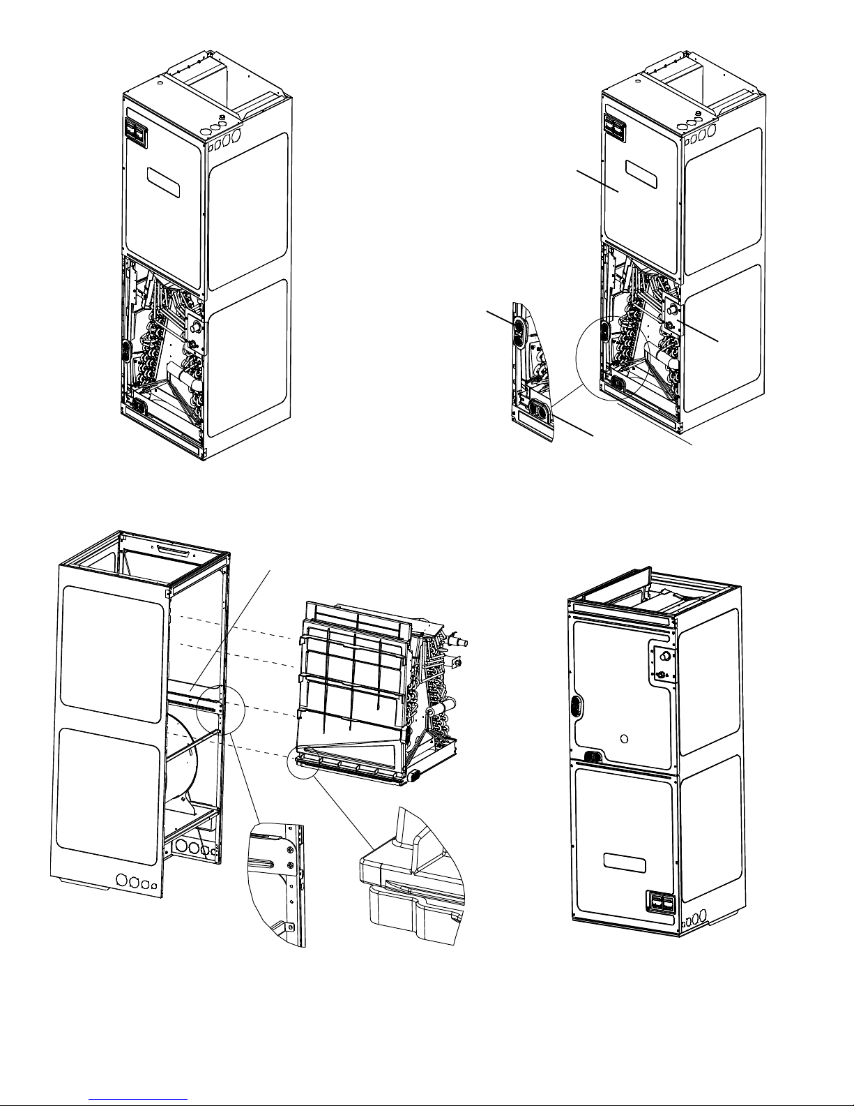
6 Installation Location
NOTE: These air handlers are designed for indoor installation
only.
The ARUF**14** and ASPT**14** product lines may be installed in
one of the upflow, downflow, horizontal left or horizontal right
orientations as shown in Figures 2, 3, 4 and 5. The unit may be
installed in upflow or horizontal left orientation as shipped (refer to specific sections for more information).
Minor field modifications are necessary to convert to downflow
or horizontal right as indicated in below sections.
Side Drain Pan Removal: Refer to Figure 1, remove the two (2)
screws that secure the drip shield support brackets to the
condensate collectors (front and back). Unsnap the side drain
pan from vertical (bottom) drain pan using a screw driver or any
small lever. The side drain pan and drip shield brackets may now
be removed. The bottom left drain connection is the primary
drain for this application and condensate drain line must be
attached to this drain connection. The bottom right drain
connection is for the secondary drain line (if used).
6.1 Upflow Installation
No field modifications are mandatory however to obtain maximum efficiency, the horizontal side drain pan & extension must
be removed.
DRIP SHIELD REMOVAL
Figure 1
6.2 Horizontal Left Installation
No field modifications are permissible for this application.
The bottom left drain connection is the primary drain for this application and condensate drain line must be attached to
this drain connection. The bottom right drain connection is
for the secondary drain line (if used).
6.3 Downflow
No field modifications are mandatory however to obtain
maximum efficiency, the horizontal side drainpan & extension must be removed.
IMPORTANT NOTE: To prevent coil pan “sweating” in the
downflow application, a downflow kit (DFK) is available
through your local distributor. The DFK is not supplied with
the air handler and is required by the manufacturer on all
downflow installations. See Table 1 for the correct DFK and
follow the instructions provided for installation.
MODEL LIST FOR DOWNFLOW KIT
DFK-B DFK-C DFK-D
DOWNFLOW KIT DOWNFLOW KIT DOWNFLOW KIT
ARUF25B14** ARUF37C14** ARUF37D14**
ARUF29B14** ARUF43C14** ARUF43D14**
ARUF31B14** ARUF49C14** ARUF47D14**
ARUF49D14**
ARUF61D14**
ASPT61D14**
DOWNFLOW KIT
Table 1
4

6.4 Horizontal Right Installation
Side drainpan extension must be removed for all models except : ARUF47D14**, ARUF61D14**, ASPT61D14**.
Refer to Figure 6 and 7 for the location of the components referenced in the following steps.
1. Before inverting the air handler, remove blower access panel and coil access panel. The coil access panel and tubing
panel may remain screwed together during this procedure. Remove and retain the seven (7) screws securing the coil
access panel to the cabinet and the six (6) screws securing the blower access panel to the cabinet.
2. Slide the coil assembly out from the cabinet. Use the drain pan to pull the assembly from the cabinet.
NOTE: DO NOT USE MANIFOLDS OR FLOWRATOR TO PULL THE COIL ASSEMBLY OUT. FAILURE TO DO SO MAY
RESULT IN BRAZE JOINT DAMAGE AND LEAKS.
3. Removal of the center support is required on units
with 21" wide cabinet. Remove and retain the two
(2) screws that secure the center support to the cabinet. Remove the center support.
4. Using the drain pan to hold the coil assembly, slide
the coil assembly back into the cabinet on the
downflow brackets as shown in Figure 8.
5. Re-install the center support (if removed) using the
two (2) screws removed in Step 4.
6. Re-install the access panels removed in Step 1 as
shown in Figure 9.
7. The bottom right drain connection is the primary drain
for this application and condensate drain line must
be attached to this drain connection. The bottom left
drain connection is for the secondary drain line (if
used). Install the PVC plug that was removed from
the side drain pan primary connection and install it
on the vertical primary connection.
NOTE: If removing only the coil access panel from the
unit, the filter access panel must be removed first. Failure to do so will result in panel damage.
UPFLOW
Figure 2
DOWNFLOW
Figure 3
HORIZONTAL LEFT
Figure 4
HORIZONTAL RIGHT
Figure 5
5
INTERNAL PART TERMINOLOGY
Figure 6
Coil Slides
on the down flow bracket
Secondary
Drain Port
for
Horizontal
Application
Blower
Access
Panel
Tubi ng
Panel
Secondary
Drain Port for
Upflow/DownflowApplication
EXTERNAL PART TERMINOLOGY
Figure 7
IMPORTANT NOTE:
Ensure coil slides on the rails along the groove provided on the drain pan side
walls. Failure to do so will result in improper condensate drainage.
COIL INSTALLATION FOR DOWNFLOW
Figure 8
ACCESS PANEL CONFIGURATION FOR DOWNFLOW
OR HORIZONTAL RIGHT
Figure 9
6

7 Refrigerant Lines
NOTE: Refrigerant tubing must be routed to allow adequate
access for servicing and maintenance of the unit.
Do not install the air handler in a location that violates
the instructions provided with the condenser. If the unit
is located in an unconditioned area with high ambient
temperature and/or high humidity, the air handler may
be subject to nuisance sweating of the casing. On these
installations, a wrap of 2" fiberglass insulation with a vapor
barrier is recommended.
7.1 Tubing Size
For the correct tubing size, follow the specification
for the condenser/heat pump.
7.2 Tubing Preparation
All cut ends are to be round, burr free, and clean.
Failure to follow this practice increases the chances
for refrigerant leaks. The suction line is spun closed
and requires tubing cutters to remove the closed end.
NOTE: To prevent possible damage to the tubing joints, do not handle coil assembly with manifold or flowrator tubes.
Always use clean gloves when handling coil assemblies.
7.3 Special Instructions
This product is factory-shipped with R410A and dry
nitrogen mixture gas under pressu re. Use appr opria te
service tools and follow these instructions to prevent
injury .
A quenching cloth is strongly recommended to prevent
scorching or marring of the equipment finish when
brazing close to the painted surfaces. Use brazing
alloy of 5% minimum silver content.
CAUTION
Applying too much heat to any tube can melt the tube. Torch
heat required to braze tubes of various sizes must be
proportiona l to the s ize of th e tub e. S erv ice p ersonn el m u st
use the appropriate heat level for the size of the tube being
brazed.
Units without a factory installed TXV come equipped with a flowrator piston for refrigerant expansion. For most
installations with matching applications, no change to the flowrator piston is required. However, in mix-matched
applications, a flowrator piston change may be required. See the piston kit chart (provided in the literature packet)
or consult your local distributor for details regarding mix-matched flowrator piston sizing. If the mix-match application requires a different flowrator piston size, change the flowrator piston in the flowrator body on the indoor
coil before installing the coil and use the procedure in section 8.4.
NOTE: The use of a heat shield is strongly recommended when brazing to avoid burning the serial plate or the finish
of the unit. Heat trap or wet rags must be used to protect heat sensitive components such as service valves and TXV
valves sensing bulb.
7.4 Tubing Connections for Flowrator Model
1. Loosen the 13/16 nut 1 TURN ONLY to allow high pressure tracer
SUCTION LINE
WITH SPIN CLOSURE
gas to escape. No gas indicates a possible leak.
2. After the gas has been expelled, remove the nut and discard the
black or brass cap plastic seal.
RUBBER
GROMMET
3. Remove the flowrator piston to verify it is the correct size for
the outdoor unit being installed and then replace the piston
(changing size, if needed). See piston kit chart in the literature
kit for appropriate piston size.
SUCTION SPUN END AND GROMMET
Figure 10
4. Remove the spin closure on the suction line using a tube cutter
and deburr the tube.
5. Insert the suction line into the connection, slide the insulation and the rubber grommet at least 18" away from the
braze joint.
6. Remove the tailpiece clamped to the exterior of the cabinet or in the literature kit packet and slide the 13/16 nut
into place.
7. Braze tailpiece to the line set liquid tube and braze suction line connection. Quench all brazed joints with a damp
rag upon completion of brazing. Do not allow water to enter the inside of the tubing.
7
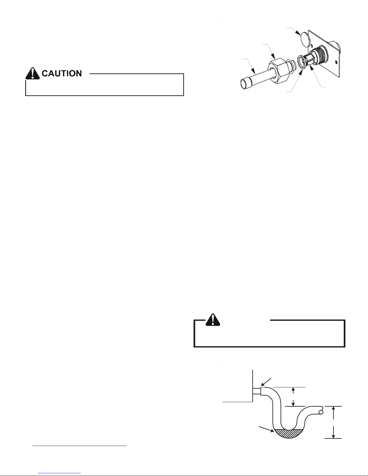
8. AFTER THE TAILPIECE HAS COOLED, confirm position of the white
Teflon® seal and hand tighten the 13/16 nut.
PLASTIC or BRASS CAP
9. Torque the 13/16 nut to 7-25 ft-lbs. or tighten 1/6 turn.
TAILPIECE
Excessive torque can cause orifices to stick. Use the
proper torque settings when tightening orifices.
13/16” NUT
WHITE
TEFLON SEAL
PISTON
TAILPIECE JOINT
7.5 Tubing Connections for TXV Models
TXV models come with factory installed TXV with the bulb pre-
Figure 11
installed on the vapor tube.
1. Remove refrigerant tubing panel or coil (lower) access panel.
2. Remove access valve fitting cap and depress the valve stem in access fitting to release pressure. No pressure indicates possible leak.
3. Replace the refrigerant tubing panel.
4. Remove the spin closure on both the liquid and suction tubes using a tubing cutter.
5. Insert liquid line set into liquid tube expansion and slide grommet about 18" away from braze joint.
6. Insert suction line set into suction tube expansion and slide insulation and grommet about 18" away from braze joint.
7. Braze joints. Quench all brazed joints with water or a wet rag upon completion of brazing.
8 Condensate Drain Lines
The coil drain pan has a primary and a secondary drain with 3/4" NPT female connections. The connectors required are 3/
4" NPT male, either PVC or metal pipe, and should be hand tightened to a torque of no more than 37 in-lbs. to prevent
damage to the drain pan connection. An insertion depth of approximately 3/8” to 1/2” (3-5 turns) should be expected at
this torque.
1. Ensure drain pan hole is not obstructed.
2. To prevent potential sweating and dripping on to finished space, it may be necessary to insulate the condensate drain
line located inside the building. Use Armaflex® or similar material.
A secondary condensate drain connection has been provided for areas where the building codes require it. Pitch all drain
lines a minimum of 1/4" per foot to provide free drainage. Provide required support to the drain line to prevent bowing.
If the secondary drain line is required, run the line separately
from the primary drain and end it where condensate discharge
can be easily seen.
NOTE: Water coming from secondary line means the coil primary drain is plugged and needs immediate attention.
If secondary drain is not installed, the secondary
access must be plugged.
Insulate drain lines located inside the building or above a finished living space to prevent sweating. Install a condensate
trap to ensure proper drainage.
NOTE: When units are installed above ceilings, or in other locations
where damage from condensate overflow may occur, it is MANDATORY
to install a field fabricated auxiliary drain pan under the coil cabinet
enclosure.
The installation must include a “P” style trap that is located as close as
is practical to the evaporator coil. See Figure 12 for details of a typical
condensate line “P” trap.
NOTE: Trapped lines are required by many local codes. In the absence
of any prevailing local codes, please refer to the requirements listed in
the Uniform Mechanical Building Code.
CAUTION
Air Handler
POSITI VE LIQUID
SEAL REQUIRED
AT TRAP
Drain
Connection
2" MIN.
3" MIN.
Figure 12
8
 Loading...