


â
Self-Cleaning
Gas Range
Owner's Manual
ARG7800*
ARG7600*
English ........................................................................ |
2 |
Français.................................................................... |
30 |
Para recibir un manual en español gratis, envíe por correo o por fax su nombre, dirección, y número de modelo a:
Amana Appliances
Consumer Communications/Spanish Manual 2800 220th Trail
PO Box 8901
Amana, Iowa 52204-0001 USA
Número de fax 1-319-522-8158
*Additional alphanumeric characters representing other models in series may follow each model number.
Please Read Manual Before Operating
Range
Installer
Leave this manual and other literature with consumer for future use.
Customer
Keep these instructions for future reference. If appliance changes ownership, be sure this manual accompanies range.

Contents
Model Identification ................................................. |
2 |
Parts and Accessories ............................................ |
2 |
Service .................................................................... |
2 |
Asure™ Extended Service Plan .............................. |
2 |
Important Safety Information ....................................... |
4 |
ALL APPLIANCES .................................................. |
4 |
SELF-CLEANING OVEN ......................................... |
4 |
OVEN ..................................................................... |
4 |
SURFACE COOKING UNITS .................................. |
4 |
Delayed Ignition ...................................................... |
4 |
VENTILATION HOOD .............................................. |
5 |
IN CASE OF FIRE .................................................. |
5 |
PRECAUTIONS ...................................................... |
5 |
Installation .................................................................. |
5 |
Packing Material ..................................................... |
5 |
Range Location ....................................................... |
5 |
Cabinet Opening ..................................................... |
5 |
Minimum Clearances to Combustible Surfaces ....... |
6 |
Special Countertop Conditions ................................ |
6 |
Electrical Connection Requirements ....................... |
6 |
Electrical Connection Clearance ............................. |
7 |
Gas Connection Requirements................................ |
7 |
Gas Supply Location............................................... |
7 |
Gas Supply Pressure .............................................. |
7 |
Pressure Regulator Location ................................... |
8 |
Oven Shutoff Valve .................................................. |
8 |
Converting for Use with Natural Gas |
|
or Propane Gas....................................................... |
8 |
Gas Connection ...................................................... |
11 |
Testing for Gas Leaks ............................................. |
12 |
Seal Openings ........................................................ |
12 |
Anti-tip Bracket Installation ..................................... |
12 |
Place Range ........................................................... |
12 |
Removal and Reinstallation of Range ...................... |
13 |
Place Grates and Burner Caps................................ |
13 |
Test and Adjust Surface Burner Flame .................... |
13 |
Test and Adjust Oven Burner Flame ........................ |
14 |
Broiler Flame .......................................................... |
15 |
Operation ................................................................... |
15 |
Operating Surface Burners ...................................... |
15 |
Operating Surface Burner during a Power Failure .... |
16 |
Cooking Utensils ..................................................... |
16 |
Electronic Oven Control .......................................... |
17 |
Setting Clock .......................................................... |
19 |
Setting Minute Timer ............................................... |
19 |
Prepare to Bake ...................................................... |
19 |
Baking .................................................................... |
20 |
Timed Baking .......................................................... |
20 |
Delayed Baking....................................................... |
20 |
Adjusting Oven Temperature .................................... |
20 |
Broiling ................................................................... |
21 |
Prepare for Self-clean and |
|
Delayed Self-clean Cycle ........................................ |
21 |
Self-cleaning ........................................................... |
22 |
Delayed Self-clean Cycle ........................................ |
22 |
Cooking Guide ........................................................... |
23 |
Baking Guide .......................................................... |
23 |
Broiling Guide ......................................................... |
23 |
Poultry Roasting Guide ........................................... |
24 |
Beef and Pork Roasting Guide ................................ |
24 |
Care and Cleaning ...................................................... |
25 |
Removing Oven Door ............................................... |
25 |
Removing Storage Drawer ....................................... |
25 |
Replacing Oven Light .............................................. |
25 |
Replacing Panel Light Bulb (ARG7800) ................... |
25 |
Cleaning .................................................................. |
26 |
Before Calling for Service ............................................ |
27 |
Warranty .................................................................... |
28 |
Quick Reference Instructions ..................................... |
29 |
Model Identification
Complete enclosed registration card and promptly return. If registration card is missing, call Consumer Affairs Department at 1-800-843-0304 inside U.S.A. 319-622-5511 outside U.S.A. When contacting Amana, provide product information located on rating plate. Rating plate is located on the oven frame. Record the following:
Model Number: ______________________________
Manufacturing Number: ________________________
Serial or S/N Number: _________________________
Date of purchase: ____________________________
Dealer’s name and address: ____________________
__________________________________________
__________________________________________
Parts and Accessories
Purchase replacement parts and additional accessories (e.g., refrigerator shelves, dryer racks, or cooktop modules) over the phone. To order accessories for your Amana product, call 1-800-843-0304 inside U.S.A. or 319-622-5511 outside U.S.A.
Service
Keep a copy of sales receipt for future reference or in case warranty service is required. Any questions or to locate an authorized servicer, call 1-800-NAT-LSVC (1-800-628-5782) inside U.S.A. 319-622-5511 outside U.S.A. Warranty service must be performed by an authorized servicer. Amana, also recommends contacting an authorized servicer if service is required after warranty expires.
Asure™ Extended Service Plan
Amana offers long-term service protection for this new range. Asure™ Extended Service Plan is specially designed to supplement Amana’s strong warranty. This plan covers parts, labor, and travel charges.
Call 1-800-528-2682 for information.
2
Important Safety Information
!WARNING
To reduce the risk of the appliance tipping, it must be secured by a properly installed anti-tip bracket(s). To make sure bracket has been installed properly, remove the storage drawer and look under the range with a flashlight. Bracket(s) must be engaged in the rear corner of the range.
•ALL RANGES CAN TIP
•INJURY TO PERSONS COULD RESULT
•INSTALL ANTI-TIP
BRACKET(S) PACKED WITH RANGE
•SEE INSTALLATION INSTRUCTIONS
!WARNING
To avoid personal injury, do not sit, stand or lean on oven door or oven drawer.
!WARNING
To avoid risk of electrical shock, personal injury, or death, make sure your range has been properly grounded and always disconnect it from main power supply before any servicing.
!WARNING
To avoid death, personal injury or property damage, information in this manual must be followed exactly.
Do not store or use gasoline or other flammable vapors and liquids in the vicinity of this or any other appliance.
WHAT TO DO IF YOU SMELL GAS
•Do not try to light any appliance.
•Do not touch any electrical switch; do not use any phone in your building.
•Immediately call your gas supplier from a neighbor’s phone. Follow the gas supplier’s instructions.
•If you cannot reach your gas supplier, call the fire department.
Installation and service must be performed by a qualified installer, service agency or the gas supplier.
!CAUTION
Do not obstruct the flow of combustion or ventilation air.
!CAUTION
This appliance contains or produces a chemical or chemicals which can cause death or serious illness and which are known to the state of California to cause cancer, birth defects or other reproductive harm. To reduce the risk from substances in the fuel or from fuel combustion make sure this appliance is installed, operated, and maintained according to the instructions in this booklet.
3

Important Safety Information
ALL APPLIANCES
1.Proper Installation —Be sure your appliance is properly installed and grounded by a qualified technician.
2.Never Use Appliance for Warming or Heating the Room.
3.Do Not Leave Children Alone—Children should not be alone or unattended in the area where the appliance is in use. They should never be allowed to sit or stand on any part of the appliance.
4.Wear Appropriate Apparel—Loose fitting or hanging garments should never be worn while using appliance.
5.User Servicing—Do not repair or replace any part of the appliance unless specifically recommended in the manual. All other servicing should be referred to a qualified technician.
6.Storage in or on Appliance—Flammable materials should not be stored in oven or near surface units.
7.Do Not Use Water on Grease Fires—Smother fire or flame, or use dry chemical or foam-type extinguisher.
8.Use Only Dry Potholders—Moist or damp potholders on hot surfaces may result in burns from steam. Do not let potholder touch elements. Do not use a towel or other bulky cloth.
SELF-CLEANING OVEN
1.Do Not Clean Door Gasket—The door gasket is essential for a good seal. Care should be taken not to rub, damage, or move the gasket.
2.Do Not Use Oven Cleaners—No commercial oven cleaner or oven liner protective coating of any kind should be used in or around any part of the liner.
3.Clean Only Parts Listed in Manual. See Cleaning section.
4.Before Self-Cleaning the Oven—Remove broiler pan, oven racks, and other utensils.
5.Remove all items from rangetop and backguard.
OVEN
1.Use Care When Opening Door—Let hot air or steam escape before removing or replacing food.
2.Do Not Heat Unopened Food Containers—Build-up of pressure may cause container to burst and result in injury.
3.Keep Oven Vents Ducts Unobstructed.
4.Placement of Oven Racks—Always place oven racks in desired location while oven is cool. If rack is removed while oven is hot, do not let potholder contact hot heating element in oven.
SURFACE COOKING UNITS
1.Use Proper Pan Size—This appliance is equipped with one or more surface burners of different sizes. Select utensils having flat bottoms large enough to cover the surface burner flame. The use of undersized utensils will expose a portion of the burner flame to direct contact and may result in ignition of clothing. Proper relationship of utensil to burner will also improve efficiency.
2.Never Leave Surface Burners—Boilover causes smoking and greasy spillovers that may ignite.
3.Protective Liners—Do not use aluminum foil to line oven bottom except as suggested in the manual. Improper installation of these liners may result in a risk of electrical shock, or fire.
4.Glazed Cooking Utensils—Only certain types of glass, ceramic, earthware, or other glazed utensils are suitable for rangetop service without breaking due to sudden change in temperature.
5.Utensil Handles Should be Turned Inward and Not Extend Over Adjacent Surface Burners—To reduce the risk of burns, ignition of flammable materials, and spillage due to unintentional contact with the utensil, the handle of a utensil should be positioned so that it is turned inward, and does not extend over adjacent surface units.
Delayed Ignition
Surface Burners
Burner should ignite within 4 seconds. If burner does not ignite within 4 seconds turn control knob to OFF position and follow directions in “Placing Grates and Burner Caps” and “Before Calling for Service” section. Try burner again. If burner still does not ignite in 4 seconds, contact an authorized servicer.
Bake Burner Flame
Allow no more than 40–60 seconds before burner ignites and heat is felt. To check for heat, open oven door to first stop and place hand over oven door. If heat is not felt, turn temperature knob to OFF position. If burner repeatedly fails to ignite, contact an authorized servicer.
Broiler Flame
Allow no more than 40–60 seconds before burner ignites and flame is seen. If burner does not ignite turn temperature knob to OFF position. If burner repeatedly fails to ignite within 40–60 seconds contact an authorized servicer.
Radiant screen style broiler flame should appear hazy or fuzzy. Haze should be no more than 3/8 inch thick. The radiant screen should begin to glow red or orange within 1–2 minutes.
4
Installation
VENTILATION HOOD
1.Clean Ventilation Hood Frequently—Grease should not be allowed to accumulate on hood or filter.
2.When flaming foods under hood, turn fan off. The fan, if operating, may spread the flame.
In Case of Fire
Fires can occur as a result of over cooking or excessive grease. Though a fire is unlikely, if one occurs, proceed as follows:
Surface Burner Fire
1.Smother the fire with a nonflammable lid or baking soda, or use a Class ABC or BC extinguisher. Not water. Not salt. Not flour.
2.As soon as it is safe to do so, turn the surface burner controls to OFF.
•As an added precaution, turn off gas supply and power at main circuit breaker or fuse box.
Oven Fires
1.If you see smoke from oven, do not open oven door.
2.Turn oven control to OFF.
3.As an added precaution, turn off gas supply and power at main circuit breaker or fuse box.
4.Turn on vent to remove smoke.
5.Allow food or grease to burn itself out in oven.
6.If smoke and fire persist, call fire department.
7.If there is any damage to components, call repair service before using range.
Packing Material
Remove protective packing material from range. Tape residue can be cleaned with a soft cloth and alcohol.
Range Location
Choose a location based on following factors.
•Drafts caused by home heating and air conditioning and open doors or windows can disrupt ventilation air pattern. Range should not be installed near windows or doors.
•Make sure there is adequate space for proper installation.
•Carefully read all instructions before beginning installation.
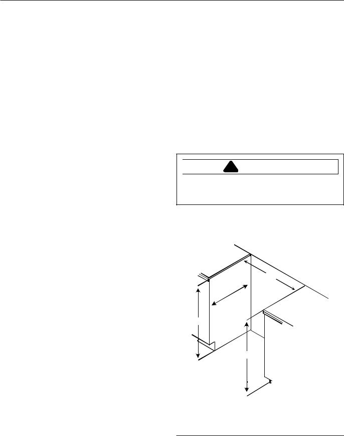
Cabinet Opening
!WARNING
To avoid risk of burns or fire by reaching over burners, cabinet storage space located above range should be avoided.
Range should extend approximately 2 inches from cabinet front to oven door handle. Use dimensions in figure below and shown in Special Countertop Conditions section to prepare cabinet opening.
Precautions
•Do not cook food directly on rangetop surface, always use cookware.
•Do not mix household cleaning products. Chemical mixtures may interact with objectionable or even hazardous results.
•Do not put plastic items on warm cooking areas. They may stick and melt.
•Do not slide rough metal objects across rangetop surface. Scratching or metal marking can result.
•Do not use damp sponge or dishcloth to clean rangetop when range is hot. Steam from sponge or dishcloth can burn.
•Do not leave fat heating unless you remain nearby. Fat can ignite if overheated by spilling onto hot surfaces.
•Do not allow pots to boil dry as this can cause damage to cooking surface and pan.
•Do not use rangetop surface as a cutting board.
A
D
C
B
A—30 1/8 to 30¼ inches
B—36 inches standard
C—35 inches standard
D—23 inches standard
Standard Cabinet and Countertop Height
5
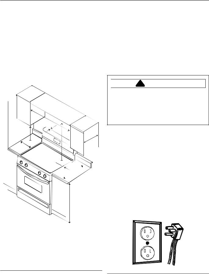
Minimum Clearances to Combustible Surfaces
•Minimum clearance to rear wall is 0 inches.
•Minimum clearance to a vertical right or left side wall extending above cooking surface is 3 inches.
•Minimum clearance to countertop/cabinet on each side is 0 inches.
•Minimum of 30 inches between top of cooking surface and bottom of an unprotected wood or metal cabinet.
•24 inches between cooking surface and protected wood or metal cabinet above range. Cabinet bottom must be protected by at least ¼ inch thick millboard with not less than No. 28 MSG sheet steel, .015 inch thick stainless steel, .024 inch thick aluminum, or .020 inch thick copper.
A
J
B
D
H
C
E 

F
G
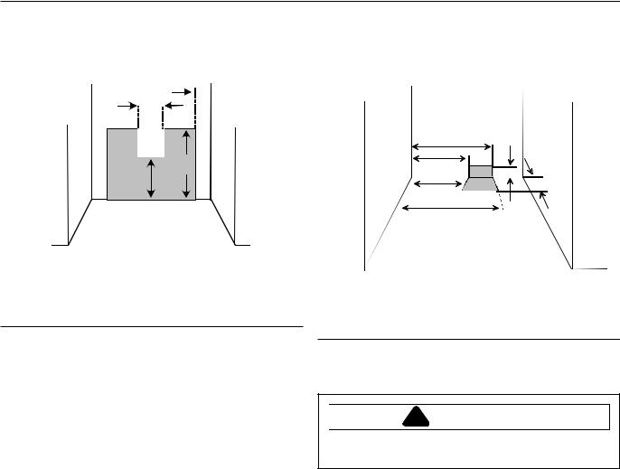
Special Countertop Conditions
Countertops such as ceramic tile tops cause cabinet and countertop to be higher than 36 inches. Follow instructions below when countertop is higher than 36 inches.
1.Raise leveling legs to maximum level.
2.Measure from floor to side trim. If measurement is less than height of countertop floor must be shimmed.
3.Shim floor using a piece of plywood same size as range opening. Secure plywood to floor. Plywood must be as secure as original flooring.
4.Install anti-tip bracket(s) and slide range into place.
Electrical Connection Requirements
!WARNING
To avoid the risk of serious electrical shock or property damage, do not cut or remove the third (ground) prong from the power plug. A 3-wire grounded conductor system must be used. Relying on the flexible connector, hard piping or any other part of the gas supply line as a ground may cause fire, electrical shock and/or erratic control operation.
Range must be electrically grounded in accordance with local codes or in the absence of local codes, with the National Electrical Code, ANSI/NFPA No. 70-Latest Edition.
In Canada, electrical connections are to made in accordance with CSA C22.1 Canadian Electrical Code. All electrical connections are to be made in accordance with CSA standards Z240.6.1 electrical requirements for mobile homes.
Use a 120 volt, 60 hertz, 3-prong receptacle protected by a 15 amp circuit breaker or time delay fuse. A qualified electrician should confirm the outlet is properly grounded.
If a 2-prong outlet is encountered, range owner must replace outlet before using range. Do not cut off cord, use plug adapter or extension cord, or remove grounding plug.
A—30 inches minimum
B— 0 inches
C—30 inches unprotected/24 inches protected minimum
D—13 inches
E—0 inches
F—25 inches maximum
G—36 inches maximum
H—3 inches minimum (Both sides of range)
J—18 inches minimum
Minimum Clearances to Combustible Surfaces
Grounded Plug and Receptacle
6
Electrical Connection Clearance
Electrical connection must be located in the area shown. Electrical connection must not interfere with gas connection.
A 
D |
B |
C |
A—2 inches (Both sides)
B—19½ inches
C—12 inches
D—6 inches
Electrical Connection Clearance
Gas Connection Requirements
Before connecting this appliance to the gas supply piping system, confirm installation meets the requirements of local codes, or in the absence of local codes, with the National Fuel Gas Code, ANSI Z223.1-Latest Edition.
When installed in mobile housing, installation is to be in accordance with CSA standard Z241.1 gas equipped mobile housing.
The installation of appliances designed for manufactured (mobile) home installation must conform with Manufactured Home Construction and Safety Standard, Title 24 CFR, Part 3280, or when such standard is not applicable, the Standard for Manufactured Home Installation, ANSI225.1/NFPA 501A-Latest Edition, or with local codes or the standard CAN/CSA-z240MH, “Mobile Homes”, and with local codes where applicable.
The installation of appliances is to be in accordance with CAN1-B149.1 or B149.2 installation code for gas burning appliances and equipment and/or local codes. Part 1 and/ or local codes.
Gas Supply Location
Gas supply must be located in the area shown. Gas connection must not interfere with the electrical connection.
A
B C
D
B
A
A—26 inches
B—20 inches
C—2¼ inches
D—4 inches
Gas Supply Location
Gas Supply Pressure
!CAUTION
To avoid property damage, maximum gas supply pressure must not exceed 14" WCP.
•Appliance and individual shutoff valve must be disconnected from the gas supply piping system during any pressure testing of that system at test pressures in excess of ½ psig (3.5kPa) (14" WCP).
•Appliance must be isolated from gas supply piping system by closing manual shutoff valve during any pressure testing of the gas supply piping system at test pressures equal to or less than ½ psig (3.5kPa) (14" WCP).
•Gas supply pressure for checking regulator setting must be at least 1" WCP above manifold pressure shown on rating label.
7
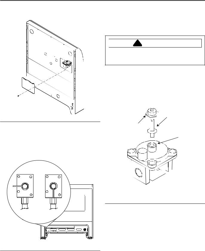
Pressure Regulator Location
Remove rear cover to expose pressure regulator.
Regulator Cover
Oven Shutoff Valve
Gas valve to oven is turned on at factory, but could accidently be turned off during installation. Verify valve is turned on.
Converting for Use with Natural Gas or Propane Gas
This range arrives from factory adjusted for use with natural gas. If using LP/propane gas is desired, range must be converted. See “Type 1” or “Type 2” regulator.
!WARNING
To avoid electric shock that can cause personal injury or death, disconnect main electrical supply to range before servicing.
Converting Type 1 Pressure Regulator for Use with LP/ Propane
1.Remove pressure regulator cap with a wrench.
2.Remove plastic insert from pressure regulator cap.
•Plastic insert fits tightly in cap.
3.Reverse plastic insert and carefully push plastic insert firmly into hole in pressure regulator cap.
•Cap must show “LPG10” or “LP10”.
B
A
C
|
H |
|
|
H |
R |
|
R |
|
A—Cap |
G |
G |
B—Plastic Insert (LP setting) |
||
|
A A |
|
A A |
|
|
|
|
|
C—Spring Location |
|
|
|
|
Type 1 Pressure Regulator |
|
Off |
|
On |
4. Place pressure regulator cap on pressure regulator |
|
|
|
|
|
|
|
|
|
and tighten. |
|
|
|
|
• Insert should not disturb spring in body of regulator. |
Check Oven Shutoff Valve |
|
|
|
|
8
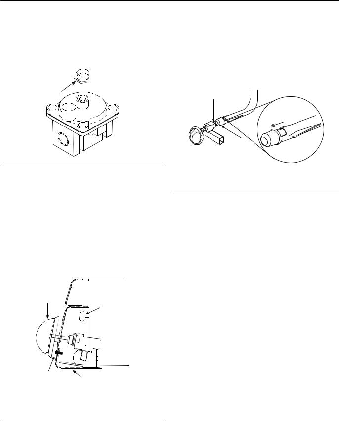
Converting Type 2 Pressure Regulator for Use with LP/Propane
1.Remove pressure regulator cap with a wrench.
2.Reverse pressure regulator cap.
• Cap must show “LP”.
3.Place pressure regulator cap on pressure regulator and tighten.
 LP
LP
Cap
Type 2 Pressure Regulator
Converting Surface Burners for Use with LP\Propane
1.Remove 4 burner control knobs from range.
•Exposes 2 screws on burner control panel.
2.Remove 2 screws from burner control panel.
•Panel drops slightly after screws are removed.
3.Grasp bottom of burner control panel, gently lift and pull out panel until clear of burner valve stems.
•After burner control panel clears valve stems, continue to roll panel until free from range. Set aside. See Pivot Point in figure.
•Gas valve and orifice hood are visible after burner control panel is removed.
A
B
4.While facing range front, turn orifice hoods counterclockwise 1½ to 2 turns or until snug.
•Use ½ inch open end or 90° offset open end wrench.
•Do not over tighten orifice hoods. If orifice hoods are over tightened, gas supply can be cutoff or orifice hoods can strip.
5.Open air shutter fully.
A
Open Fully
B
A—Orifice Hood
B—Air Shutter
Converting Surface Burners for Use with LP\Propane
6.Reassemble burner control panel after adjusting air shutter.
• See Adjusting Surface Burner Flame section.
D |
C |
|
A—Burner Control Knob
B—Pivot Point
C—Burner Control Panel
D—Screw
Burner Control Panel
9
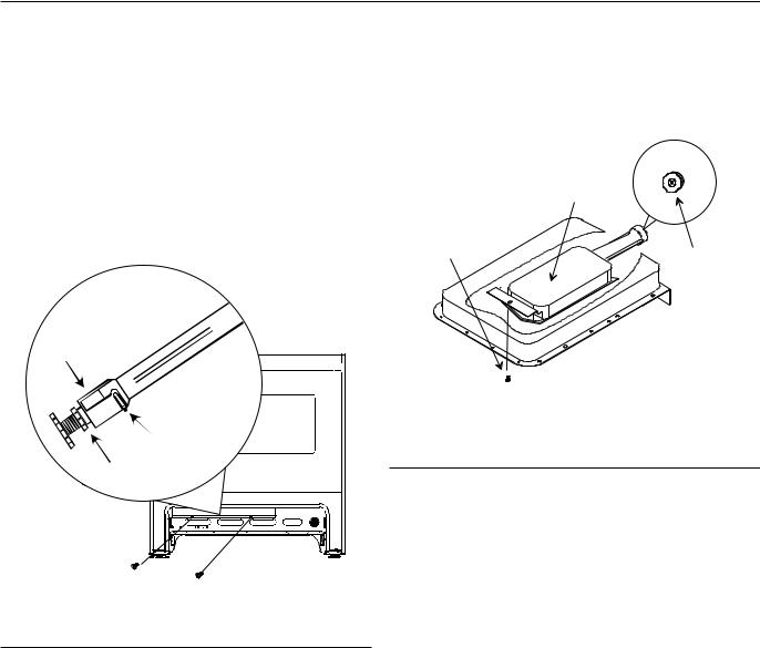
Converting Oven Burner for Use with LP\Propane
1.Remove storage drawer.
•See Removing Storage Drawer section.
2.Locate and remove 2 screws attaching Z-shaped cover plate.
•Cover plate located in center, rear of storage drawer cavity.
•Removing cover plate exposes oven burner orifice and air shutter.
3.Turn orifice hood clockwise until snug.
•Do not overtighten orifice hoods. Orifice hoods can strip.
4.Replace cover plate and storage drawer.
with 5/16 inch socket wrench and replace with LP/ propane burner spud stamped “58”.
•Attach unused burner spud near regulator for future use.
5.Reinstall broiler and, if necessary, oven door.
B
A
C
C
A |
B |
A—Air Shutter Screw
B—Orifice Hood
C—Air Shutter
Converting Oven Burner
Converting Broiler Burner for Use with LP\Propane
1.Locate orifice spud attached adjacent to pressure regulator and remove for later use.
•Orifice spud used for LP/propane gas is silver and is stamped “58”.
2.Open oven door and locate broiler burner on oven ceiling.
•Remove oven door to make conversion easier. See
Removing Oven Door section.
3.Remove 2 screws securing front of burner to oven ceiling and remove broiler.
•Be careful not to damage ignitor while removing broiler.
4.Unscrew natural gas burner spud stamped “52”
A—Screw
B—Broiler
C—Spud/Orifice
Converting Broiler Burner
Converting Type 1 Pressure Regulator for Use with Natural Gas
1.Remove pressure regulator cap with a wrench.
2.Remove plastic insert from pressure regulator cap.
•Plastic insert fits tightly in cap.
3.Reverse plastic insert and carefully push plastic insert firmly into hole in pressure regulator cap.
•Insert must show “NAT” or be blank.
4.Place pressure regulator cap on pressure regulator and tighten.
•Insert should not disturb spring in body of regulator.
Converting Type 2 Pressure Regulator for Use with Natural Gas
1.Remove pressure regulator cap with a wrench.
2.Reverse pressure regulator cap.
• Insert shows “NAT” or is blank.
3.Place pressure regulator cap on pressure regulator and tighten.
10
Converting Surface Burners for Use with Natural Gas
1.Remove 4 burner control knobs from range.
•Exposes 2 screws on burner control panel.
2.Remove 2 screws from burner control panel.
•Panel drops slightly after screws are removed.
3.Grasp bottom of burner control panel, gently lift and pull out panel until clear of burner valve stems.
•After burner control panel clears valve stems, continue to roll panel until free from range. Set aside.
•Gas valve and orifice hood are visible after burner control panel are removed.
4.While facing range front, turn orifice hoods clockwise 1½ to 2 turns.
•Use ½ inch, 90° offset crescent wrench.
5.Reassemble burner control panel after adjusting air flow to surface burner flame.
•See Adjusting Surface Burner Flame section.
Converting Oven Burner for Use with
Natural Gas
1.Remove storage drawer.
•Removing Storage Drawer section.
2.Locate and remove 2 screws attaching Z-shaped cover plate.
•Cover plate located in center, rear of storage drawer cavity.
•Removing cover plate exposes oven burner orifice and air shutter.
3.Turn orifice hood counterclockwise 2 full turns.
4.Replace cover plate and storage drawer.
Converting Broiler Burner for Use with
Natural Gas
1.Locate orifice spud attached adjacent to pressure regulator and remove for later use.
•Orifice spud used for natural gas is brass and is stamped “52”.
2.Open oven door and locate broiler burner on oven ceiling.
•Remove oven door to make conversion easier. See
Removing Oven Door section.
3.Remove 2 screws securing front of burner to oven ceiling and remove broiler.
•Be careful not to damage ignitor as you remove broiler.
4.Unscrew LP/propane burner spud stamped “58” with 5/16 inch socket wrench and replace with natural gas burner spud stamped “52”.
5.Reinstall broiler and, if necessary, oven door.
Gas Connection
Connect gas supply to regulator using hard pipe or flexible connector (Check local codes). Pressure regulator supplied with this appliance has a ½ inch NPT female connection. If gas union is used, remove storage drawer, slide range into place, and connect union.
•Refer to National Fuel Gas Code or local codes for supply pipe size requirements to assure sufficient gas supply to unit.
•A manual shutoff, not supplied with range, must be installed in an accessible location outside of range.
•Use joint compound that is resistant to action of propane gas on all male pipe threads.
•Use supplied pressure regulator only.
•Do not overtighten gas fitting when attaching to pressure regulator. Overtightening may crack regulator.
•Support pressure regulator with wrench when installing gas fitting.
!WARNING
To avoid property damage or personal injury, only use a new flexible connector that is AGA/CGA design certified.
•Do not use an old connector.
•Do not reuse a connector after moving appliance.
A
B
 C
C
D
A—Regulator
B—Adaptor
C—Flexible Connector
D—Manual Shut Off Valve
Flexible Connection
11
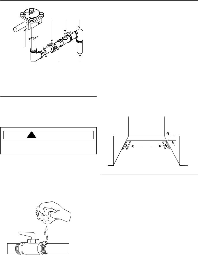
A B C
F
E D
A—Union
B—Manual Shut Off Valve
C—Reducing Elbow (3/4-inch to 1/2-inch)
D—3/4-inch Stub
E—1/2-inch Nipple
F—Regulator
Hardpipe Connection
Testing for Gas Leaks
After final gas connection is made, turn on manual gas valve and test all connections in gas supply piping and range for gas leaks.
Seal Openings
Openings in wall behind the range or on floor under range must be sealed before sliding range into position.
Anti-tip Bracket Installation
To reduce risk of range tipping, secure range with a properly installed anti-tip bracket.
1.Measure 31/2 inches from back wall on right and left side of cabinet cutout. Mark measurements on floor and draw a straight line connecting marks.
2.Position anti-tip bracket.
•If range is installed beside cabinet(s), place anti-tip bracket with back edge on line drawn on floor and side of bracket against cabinet.
•If range is not installed beside cabinet(s), position range where it will be installed. Draw a line along side of range on floor from front to back. Remove range. Place anti-tip bracket with back edge over line drawn 31/2 inches from back wall and side of bracket over line drawn along side of range on floor.
•Anti-tip bracket can be installed on either right or left side.
!WARNING
To avoid property damage or serious personal injury, never use a lighted match to test for gas leaks.
1.Place soap suds on connection.
•Bubbles appear if leak is present.
2.If bubbles appear, shut off gas supply valve.
3.Tighten joint if leak is at factory fitting.
•If leak is not at factory fitting, unscrew, apply more joint compound, and tighten to correct leak.
4.Retest connection for leak after tightening.
•Retest any connections that were disturbed.
3 1/2"
or
Anti-tip Bracket Installation
3.Mark 2 hole locations in anti-tip bracket.
4.Drill 2 holes.
•If drilling into wood, use a 3/32 inch drill bit.
•If drilling into concrete, use a 3/16 inch masonry drill bit and insert plastic anchors.
5.Secure bracket to floor using screws supplied.
6.Slide range into position.
7.Remove range storage drawer and confirm anti-tip bracket is engaged with range leveling leg after range is in place.
Place Range
Plug in range. Slide range into place. Carefully level range using legs provided. Range must be level to cook and bake uniformly.
|
• |
Place a level on top oven rack or on top of range when |
|
|
leveling. |
|
• |
Leveling legs must be extended out ¼ inch to engage |
Test for Gas Leaks |
||
|
12 |
anti-tip bracket. |
|
|
Removal and Reinstallation of Range |
Correct |
|
1. |
Unplug range cord. |
|
2. |
Turn off gas valve and disconnect gas supply. |
|
3.Remove range and place aside.
4.Remove anti-tip bracket and reinstall anti-tip bracket into new location using instructions provided with bracket.
5. To reinstall range, follow instructions in Installation section of this manual.
• Do not reuse a flexible connector after moving appliance.
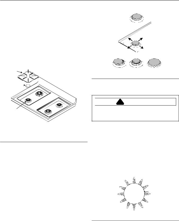
Place Grates and Burner Caps
Place burner cap on burner base and grate on rangetop.
A
B 


C
A—Burner grate
B—Burner cap
C—Burner base
Place Grates and Burner Caps
Pegs in the burner base fit into recess in underside of burner cap. To make sure cap is properly aligned and leveled, move burner cap around on burner base. Burner cap must be correctly seated on burner base for proper operation of burner.
Make sure proper cap size is on each burner base. Burner does not burn properly if wrong size burner cap is placed on burner base.
Turn on burners to check for proper operation. See Operating Surface Burners section for burner operating instructions.
Not centered Too small |
Too large |
Burner Caps
Test and Adjust Surface Burner Flame
!WARNING
To avoid electric shock that can cause personal injury or death, disconnect main electrical supply to range before servicing.
Turn on burner. See Operating Surface Burners section for burner operating instructions. Surface burner should ignite within 4 seconds. Properly adjusted surface burner flames are clean and blue with a distinct inner cone approximately ¼ inch to ½ inch long. Some yellow flame is normal when burning LP/Propane.
See Adjusting Air Shutter section,
•If burner flame is blowing or noisy, reduce airflow to burner.
•If burner flame does not hold its shape, increase airflow to burner.
 A
A
Burner
A—¼ inch to ½ inch long
Surface Burner Flame
13

Adjusting Air Shutter
1.Remove 4 burner control knobs from range.
•Exposes 2 screws on burner control panel.
2.Remove 2 screws from burner control panel.
•Panel drops slightly after screws are removed.
3.Grasp bottom of burner control panel, gently lift and pull out panel until clear of burner valve stems.
•After burner control panel clears valve stems, continue to roll panel until free from range. Set aside. See Pivot Point in figure.
•Gas valve and orifice hood are visible after burner control panel is removed.
A |
B |
|
|
D |
C |
|
A—Burner Control Knob
B—Pivot Point
C—Burner Control Panel
D—Screw
Burner Control Panel
4.Slide air shutter open or closed depending on appearance of burner flame.
•If flame is yellow and does not hold its shape, open air shutter.
•If flame is blowing or noisy, close air shutter.
5.Reassemble burner control panel.
Close
Open
Adjusting Air Shutter
Test and Adjust Oven Burner Flame
Properly adjusted oven burner flames are blue with a distinct deep blue inner cone approximately ½ inch long. When using natural gas, flame should not have any yellow flame when burning. Some yellow flame when burning LP\propane gas is normal.
1/2"
Properly Adjusted Flame
Flame should not be visible in the oven cavity when burning and should not extend into the oven cavity beyond the removable oven bottom.
Removing Oven Bottom
!CAUTION
To avoid risk of cuts, wear protective gloves when removing oven bottom. Sharp edges around oven bottom can cut.
1.Pull oven bottom forward and lift out.
2.Replace oven bottom. Oven bottom has tabs in rear that fit into oven floor slots.
Burner Area
14
Operation
Adjust Oven Burner Flame
1.Remove storage drawer.
•See Removing Storage Drawer section.
2.Locate and remove 2 screws attaching Z-shaped cover plate.
•Cover plate located in center, rear of storage drawer cavity.
•Removing cover plate exposes oven burner orifice and air shutter.
3.Loosen air shutter lock screw and open or close air shutter.
•If burner flame is blowing or noisy, reduce airflow to burner.
•If burner flame is yellow and does not hold its shape, increase airflow to burner.
•Tighten air shutter lock screw after adjusting.
4.Replace cover plate and storage drawer.
C
A |
B |
A—Air Shutter Screw
B—Orifice Hood
C—Air Shutter
Adjusting Oven Burner Flame
Broiler Flame
Radiant Screen Style
Broiler flame should appear hazy or fuzzy. Haze should be no more than 3/8 inch thick. The radiant screen should begin to glow red or orange within 1–2 minutes.
Because broiler has a fixed orifice it can not be adjusted. Broiler does not have an air shutter.
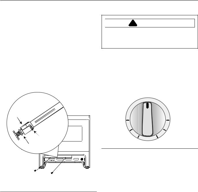
Operating Surface Burners
!WARNING
To avoid risk of serious personal injury, property damage, or fire, do not leave burners unattended while in operation. Grease and spillovers can ignite causing
afire.
1.Push burner knob in and turn control knob counterclockwise to LITE position.
•Burner should ignite within 4 seconds. If burner does not ignite within 4 seconds turn control knob to OFF position and follow directions in “Placing Grates and Burner Caps” and “Before Calling for Service” section. Try burner again. If burner still does not ignite in 4 seconds, contact an authorized servicer.
|
O F F |
|
|
L |
|
|
I |
|
O |
T |
|
E |
||
L |
||
H |
||
|
||
|
I |
MED
Burner Knob
2.After gas ignites, turn control to desired setting.
•Each control knob can be set to any required cooking temperature. Burner settings do not have distinct clicks.
•Use HI to bring food to boiling temperatures. When food is boiling temperature setting should be reduced.
•After lighting burner do not operate burner for long periods of time without cookware on the grate. The finish on the grate can chip without cookware to absorb heat.
3.Turn control knob to OFF position when finished cooking.
15
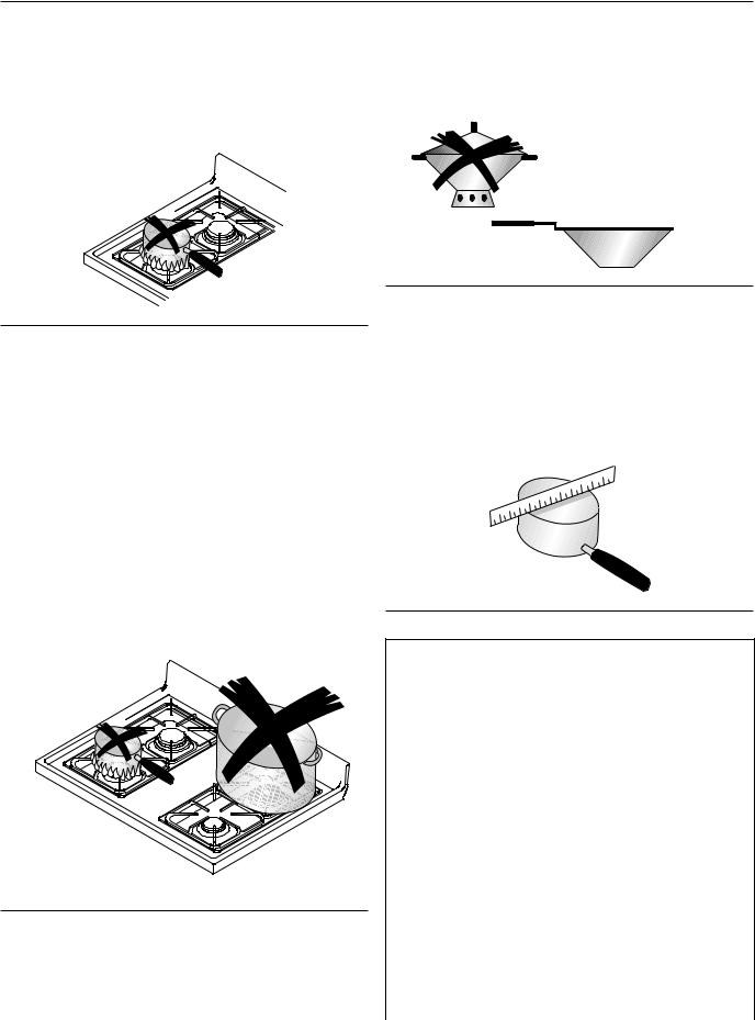
Adjusting Burner Flame Size
•While turning the burner control knob, watch the burner flame.
•Flame size should match the size of the pan. Do not allow the flame to extend up the sides of the pan. Flames that extend up the sides of the pan can ignite clothing, make handle hot, or burn.
•Do not use stove top grills on your range. Stove top grills cause incomplete combustion and can create levels of carbon monoxide above allowable standards.
•Do not use a wok with a ring stand. Use flat bottom wok.
Adjusting Burner Flame Size
Operating Surface Burner during a Power Failure
Although the system that lights the burners is electric, surface burners can be ignited during a power failure. Never attempt to light bake or broil burners during power failure.
1.Hold match at base of desired burner.
2.Push in burner control knob and turn to LITE position.
3.After gas ignites, remove match from burner and turn burner control knob to desired setting.
Woks
To avoid pan wobbling, use a pan with a flat bottom. Determine if pan has a flat bottom.
1.Rotate a ruler along bottom of pan. If pan is not flat, gaps between bottom of pan and edge of ruler occur.
2.A small groove or mark on a pan does not effect cooking times. However, if a pan has a gap, formed rings, or an uneven bottom, it does not cook efficiently and in some cases may not boil liquid.
Cooking Utensils
•Use proper pan size. Do not use a pan that has a smaller bottom than surface burner. Do not use utensils that overhang grate by more than 1 inch.
Does not cover burner
More than 1 inch overhang
Use Proper Pan Size
•Use care when using glazed cooking utensils. Some glass, earthenware, or other glazed utensils break due to sudden temperature changes.
•Select utensils without broken or loose handles.
•Handles should not be heavy enough to tilt pan.
Flat Pan Test
Utensil Material Characteristic
Type |
Temperature |
Uses |
|
Response |
|
|
|
|
Aluminum |
Heats and |
Frying, braising, |
|
cools quickly |
roasting |
|
|
|
Cast Iron |
Heats and |
Low heat |
|
cools slowly |
cooking, frying |
|
|
|
Copper Tin |
Heats and |
Gourmet |
Lined |
cools quickly |
cooking, wine |
|
|
sauces, egg |
|
|
dishes |
|
|
|
Enamelware |
Depends on |
Low heat |
|
base metal |
cooking |
|
|
|
Ceramic (Glass) |
Heats and |
Low heat |
|
cools slowly |
cooking |
|
|
|
Stainless Steel |
Heats and |
Soups, sauces, |
|
cools at |
vegetables, |
|
moderate rate |
general cooking |
|
|
|
16
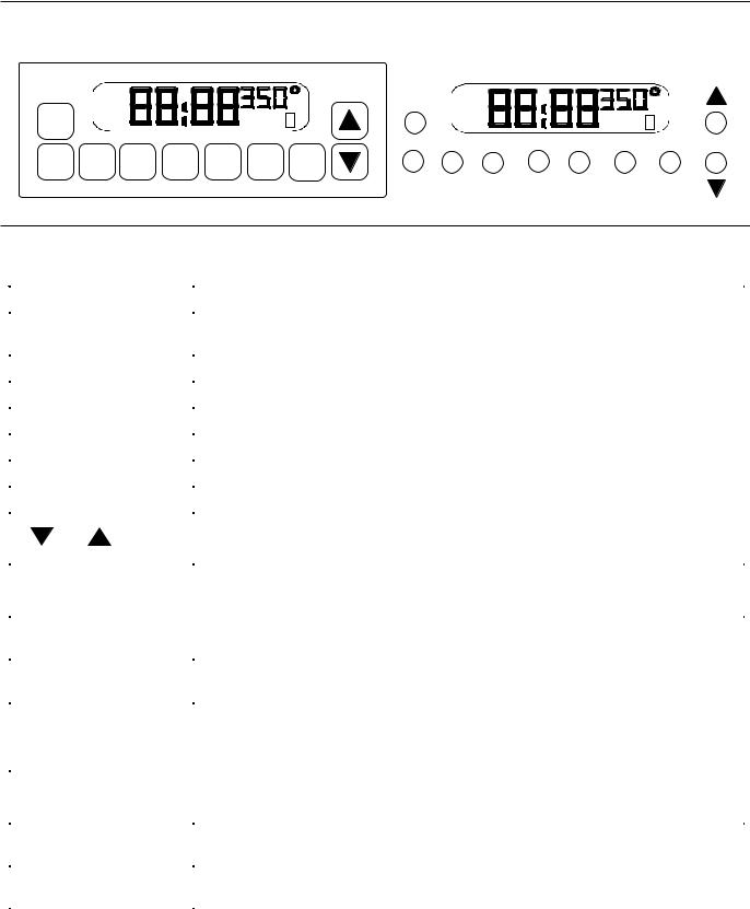
Electronic Oven Control
|
DELAY |
|
|
|
|
|
|
|
OVEN ON |
|
|
|
|
||
|
CLEAN |
|
|
|
|
|
|
OVEN |
STOP |
|
|
|
BAKE BROIL |
O |
|
CANCEL |
TIME |
|
|
|
CLEAN LOCK |
N |
|
|
|
|
|
|
|
||
TIMER |
CLOCK |
STOP |
COOK |
CLEAN |
INSTA- |
BAKE |
|
ON/OFF |
TIME |
TIME |
BROIL |
||||
|
|
|
|||||
SELF CLEAN OVEN
OVEN |
DELAY |
|
|
CANCEL |
OVEN ON |
|
|
CLEAN |
|
|
|
|
|
|
|
|
STOP |
BAKE BROIL |
O |
|
TIMER |
CLEAN LOCK |
N |
ENTRY
TIMER |
CLOCK |
STOP |
COOK |
CLEAN |
INSTA - |
BAKE |
ON/OFF |
|
TIME |
TIME |
|
BROIL |
|
ARG7600 and ARG7800 Electronic Oven Control
Pad |
Description |
OVEN CANCEL |
Cancels any cooking or cleaning function except timer. |
|
|
TIMER ON/OFF |
Use to time any kitchen function or cancel timer. Does not control bake, broil, or |
|
clean function. |
|
|
CLOCK |
Use to set time of day. |
|
|
STOP TIME |
Use to set delayed bake and self-clean. |
|
|
COOK TIME |
Use to set timed baking. |
|
|
CLEAN |
Use to select self-clean cycle. |
|
|
INSTA-BROIL |
Use to select broil. |
|
|
BAKE |
Use to select bake. |
|
|
or |
Use to set temperature or time. |
|
|
|
|
Oven Signals |
|
|
|
Timer signal |
When time elapses, timer beeps 3 times then approximately once every 6-8 |
|
seconds until TIMER ON/OFF pad is pressed. |
|
|
Preheat signal |
After setting oven to bake and selecting a temperature, oven preheats. When |
|
oven reaches set temperature, 1-second signal sounds. |
|
|
End-of-Cycle signal |
When a timed cooking cycle is complete, three long signals sound. Then, once |
|
every 6-8 seconds for 5 minutes or until OVEN CANCEL pad is pressed. |
|
If minute timer end of cycle signal is sounding, push TIMER ON/OFF pad. |
|
|
Oven Switches |
|
|
|
Panel Light (ARG7800) |
Used to light backguard and illuminate cooking surface. |
(Not Shown) |
|
|
|
Oven Light Switch |
Oven light turns on when oven door is opened or when switch on control panel is |
(Not Shown) |
turned on. |
|
|
17
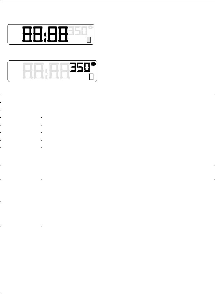
Display
DELAY
OVEN ON
CLEAN
STOP
TIME
Display Glossary
Displays time-of-day, timer, and timed or delayed bake settings.
BAKE BROIL O
CLEAN LOCK N
Displays temperature and cooking method for oven.
TIME |
TIME displays while time-of-day, timed or delayed baking, or delayed self-cleaning is set. |
|
|
|
|
BAKE |
BAKE displays while bake is set and used. |
|
|
|
|
ON |
Displays when oven is heating. |
|
|
|
|
DELAY |
Displays when delayed bake or clean self-cycle is set. Oven is not heating. |
|
|
|
|
STOP |
Displays when setting the stop time for a delayed baking or self-clean cycle. |
|
|
|
|
BROIL |
Displays when a broil is set and used. |
|
|
|
|
CLEAN |
Displays when self-clean cycle is set and used. |
|
|
|
|
LOCK |
LOCK flashes while oven door is locking and remains in display while door is locked. After |
|
|
cycle is complete and oven has cooled to a safe temperature, LOCK no longer displays |
|
|
and door can be opened. |
|
|
|
|
Other Features |
|
|
|
|
|
12-hour automatic |
This safety feature prevents oven from continuing to operate if it has been left on for |
|
cancel |
over 12 hours. If a cooking function continues longer than 12 hours without any options |
|
|
on oven control being touched, this feature turns oven off. Any time an option is touched, |
|
|
12-hour automatic cancel is reset. |
|
|
|
|
Child lockout |
This safety feature is used to prevent children from accidentally programming oven by |
|
disabling electronic oven control. Press and hold BAKE and COOK TIME for 5 seconds. |
||
|
||
|
“OFF” displays where the temperature normally appears. To reactivate control, press and |
|
|
hold BAKE and COOK TIME pads for 5 seconds on the upper oven control. Child lockout |
|
|
must be reset after a power failure. |
|
Service codes and |
Electronic oven control is equipped with a self diagnostic system. Self diagnostic system |
|
tones |
alerts you if there is a error or problem in the control. If electronic range control sounds a |
|
|
series of short, rapid beeps for over 16 seconds and display shows a F-code, record the F- |
|
|
code shown. Some F-codes can be cleared by touching OVEN CANCEL or disconnecting |
|
|
power to the range. If the code continues to reoccur, disconnect electrical supply and |
|
|
contact an authorized servicer. |
|
|
F1—Control malfunction |
|
|
F2—High oven temperature |
|
|
F3—Temperature sensor malfunction |
|
|
F4—Temperature sensor malfunction |
|
|
F7—Touch pad malfunction |
|
|
F9—Door lock malfunction (Door unlocked) |
|
|
FF—Door lock malfunction (Door locked) |
|
|
|
18
 Loading...