

Page 1
Vipros 357 Queen with Fanuc 18P Control Layout Drawings ©Amada America, Inc.
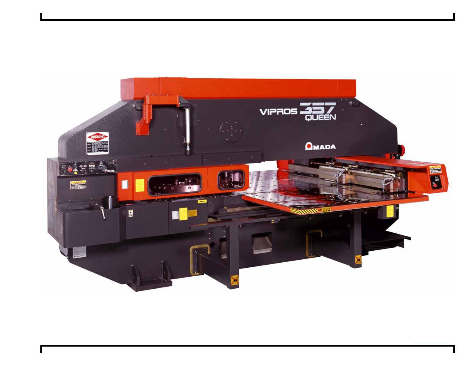
Vipros 357 Queen with Fanuc 18P Control
Layout Drawings
Amada America I nc.
7025 Firestone Blvd.
Buena Park CA. 90621
Phone: (714) 739 2111
Fax: (714) 739 4099
Email info@amada.com
Print Date 01/25/2001 Revision 4. 0 This document availabl e on t he World Wide Web at http://www.amada.com Page 1 of 10
Page 2
Vipros 357 Queen with Fanuc 18P Control Layout Drawings ©Amada America, Inc.
Warning
• Qualified personnel must complete all work.
• Do not apply power to the Vipros 357 Queen until an A.E.S.I. (Amada Engineering
and Service Incorporated) Engineer is present and has instructed you to do so.
• Not all information required for proper installation, of the Vipros 357 Queen is
included with this document. Specific details for proper installation are found in
the document Vipros 357 Queen with Fanuc 18P User Pre-installation Guide
available at the Amada America Internet web site at http://www.amada.com.
• Considerable effort has been made to ensure that this manual is free of
inaccuracies and omissions. However, as we are constantly improving our
product, some of the data contained herein may be out of date. Please check our
Internet site, http://www.amada.com, for the latest release of this document.
Print Date 01/25/2001 Revision 4. 0 This document availabl e on t he World Wide Web at http://www.amada.com Page 2 of 10
Page 3

Vipros 357 Queen with Fanuc 18P Control Layout Drawings ©Amada America, Inc.
Table Of Contents
Planning the Location of the Machine..............................................................................................................................................4
Plan View – Vipros 357 Queen........................................................................................................................................................5
Plan View – Vipros 357 Queen with V357hs Conveyor....................................................................................................................6
Plan View – Vipros 357 Queen with V357hs Conveyor and MP1225 Loader..................................................................................7
End View - Vipros 357 Queen..........................................................................................................................................................8
Elevation View –Vipros 357 Queen..................................................................................................................................................9
SBC EX 5.5Chiller Placement........................................................................................................................................................10
Print Date 01/25/2001 Revision 4. 0 This document availabl e on t he World Wide Web at http://www.amada.com Page 3 of 10
Page 4

Vipros 357 Queen with Fanuc 18P Control Layout Drawings ©Amada America, Inc.
Planning the Location of the Machine
The following diagrams provide the details for positioning your new machine.
! Not all information required for proper installation, of the Vipros 357 Queen is included with this document. Specific details
for proper installation are found in the document Vipros 357 Queen with Fanuc 18P User Pre-installation Guide available at
the Amada America Internet web site at http://www.amada.com.
! No obstacles are allowed in the worksheet travel area and the ceiling must be at least 40" above the top of the Vipros 357
Queen.
! All of the Recommended Safety / Maintenance areas should be used, but you must at least ensure that the doors of the
Fanuc 18P control unit can be opened. Any reduction of the Recommended Safety / Maintenance areas may increase the
possibility of personnel injury and increase the time and cost of installation or maintenance.
! The Vipros 357 Queen and Fanuc 18P control must be protected from direct sunlight or other heat sources. Exposure to
direct heating sources such as infrared heaters have been shown to affect punch and die alignment.
! The positioning of the SBC EX 5.5 Chiller is very flexible.
Print Date 01/25/2001 Revision 4. 0 This document availabl e on t he World Wide Web at http://www.amada.com Page 4 of 10
Page 5

Vipros 357 Queen with Fanuc 18P Control Layout Drawings ©Amada America, Inc.
t
55"
59"
E2
S
e
Plan View – Vipros 357 Queen
Electrical Requirements
Vipros 357 Queen
E1
230 / 460 / 3 / 60 ±10% 30 kVA
76 amps @ 230 / 3 / 60 VAC
38 amps @ 460 / 3 / 60 VAC
SBC EX5.5 Chiller
E2
230 or 460 / 3 / 60 ±10% 15 kVA
37 amps @ 230 / 3 / 60 VAC
19 amps @ 460 / 3 / 60 VAC
Compressed Air Requirements
P1
Vipros 357 Queen
80 psi @ 8.8 ft³/min.
59.37" Maximum
SBC 5.5 Chiller
37"
Optional Material
Supports Required
57"
Hydraulic Uni
"
30"
10"
14"
VIPROS 357 QUEEN
E1
Fanuc 18P Control
"
50" Working Range
183.8" Machine Length
323.4" Recommended Safety / Maintenance Area 40" from all components
100" Maximum Travel Area 50" Material
Optional Material
Supports Required
P1
Machine
Centerline
72.0" to Load Position
74.41" to Edge of Table
148.82" Machine Width
288.0" Maximum Material Travel Area 144" Material
368" Recomended Safety / Maintenance Area 40" from all components
"12"
cal
Print Date 01/25/2001 Revision 4. 0 This document availabl e on t he World Wide Web at http://www.amada.com Page 5 of 10
Page 6

Vipros 357 Queen with Fanuc 18P Control Layout Drawings ©Amada America, Inc.
t
55"
59"
S
e
Plan View – Vipros 357 Queen with V357hs Conveyor
Electrical Requirements
Vipros 357 Queen
E1
230 / 460 / 3 / 60 ±10% 30 kVA
76 amps @ 230 / 3 / 60 VAC
38 amps @ 460 / 3 / 60 VAC
SBC EX5.5 Chiller
E2
230 or 460 / 3 / 60 ±10% 15 kVA
37 amps @ 230 / 3 / 60 VAC
19 amps @ 460 / 3 / 60 VAC
V357hs Conveyor
E3
208 - 230 / 460 / 3 / 60 ±10% .8 kVA
2.1 amps @ 208 / 3 / 60 VAC
2.0 amps @ 230 / 3 / 60 VAC
1.0 amps @ 460 / 3 / 60 VAC
Compressed Air Requirements
Vipros 357 Queen
P1
80 psi @ 8.8 ft³/min.
SBC 5.5 Chiller
37"
59.37" Maximum
Optional Material
Supports Required
50" Working Range
183.8" Machine Length
57"
Hydraulic Uni
"
10"
14"
VIPROS 357 QUEEN
30"
E1
Fanuc 18P Control
"
100" Maximum Travel Area 50" Material
389" Recommended Safety / Maintenance Area 40" from all components
P1
Machine
Centerline
66"
E3
148.82" Machine Width
288.0" Maximum Material Travel Area 144" Material
368" Recomended Safety / Maintenance Area 40" from all components
V357hs Conveyor
39"
Access Required
this area for
scrap removal
72.0" to Load Position
74.41" to Edge of Table
Optional Material
Supports Required
"12"
cal
Print Date 01/25/2001 Revision 4. 0 This document availabl e on t he World Wide Web at http://www.amada.com Page 6 of 10
Page 7

Vipros 357 Queen with Fanuc 18P Control Layout Drawings ©Amada America, Inc.
t
55"
59"
0"
Plan View – Vipros 357 Queen with V357hs Conveyor and MP1225 Loader
Electrical Requirements
Vipros 357 Queen
E1
230 / 460 / 3 / 60 ±10% 30 kVA
76 amps @ 230 / 3 / 60 VAC
38 amps @ 460 / 3 / 60 VAC
E2
SBC EX5.5 Chiller
230 or 460 / 3 / 60 ±10% 15 kVA
37 amps @ 230 / 3 / 60 VAC
19 amps @ 460 / 3 / 60 VAC
V357hs Conveyor
E3
208 - 230 / 460 / 3 / 60 ±10% .8 kVA
2.1 amps @ 208 / 3 / 60 VAC
2.0 amps @ 230 / 3 / 60 VAC
1.0 amps @ 460 / 3 / 60 VAC
MP1225 Loader
E4
200 / 3 / 60 ±10%, 10 Kva
To operate at 230 / 460 VAC a step up
transformer with the following service is
required
29 amps @ 200 / 3 / 60 VAC
26 amps @ 230 / 3 / 60 VAC
13 amps @ 460 / 3 / 60 VAC
Compressed Air Requirements
P1
Vipros 357 Queen
P2
MP1225 Loader 75 psi @ 31.8 ft³/min.
80 psi @ 8.8 ft³/min.
SBC 5.5 Chiller
37"
59.37" Maximum
Optional Material
Supports Required
50" Working Range
183.8" Machine Length
57"
Hydraulic Uni
"
E2
1
14"
VIPROS 357 QUEEN
30"
E1
Fanuc 18P Control
28"
MP1225
E4
Xformer
P2
65.95"
188.06" MP1225 Length
100" Maximum Travel Area 50" Material
389" Recommended Safety / Maintenance Area 40" from all components
P1
Machine
Centerline
66"
E3
148.82" Machine Width
288.0" Maximum Material Travel Area 144" Material
441" Recommended Safety / Maintenance Area 40" from all components
V357hs Conveyor
39"
Access Required
this area for
scrap removal
72.0" to Load Position
74.41" to Edge of Table
75.41" to Edge of MP1225
Optional Material
Supports Required
Forklift Access
Required This Area
For Material / Parts
Loading / Unloading
141.74" MP1225 Loader Width
217.15"
MP1225 Loader
12"12"12"
Scale
Print Date 01/25/2001 Revision 4. 0 This document availabl e on t he World Wide Web at http://www.amada.com Page 7 of 10
Page 8

Vipros 357 Queen with Fanuc 18P Control Layout Drawings ©Amada America, Inc.
End View - Vipros 357 Queen
22.8"
12"12" 12"
Scale
7.9"
3.9"
19.7"
29.5"
35.4"
98.7"
110.6"
Shipping Width w/o Crate
148.8"
Print Date 01/25/2001 Revision 4. 0 This document availabl e on t he World Wide Web at http://www.amada.com Page 8 of 10
Page 9

Vipros 357 Queen with Fanuc 18P Control Layout Drawings ©Amada America, Inc.
Elevation View –Vipros 357 Queen
Center of Track 200
Material Pass Line
37.7"*
52.2"
Throat Depth
15.9" 50.0"
7.9"
QUEEN
8.7"
Y-axis 0" Reference
25.8"56.9"
1.8"
19.7"
10.0"
90.9"
12"12" 12"
Scale
28"
Fanuc
Control
Hydraulic
Unit
63.0"
52.0"
9.8"32.9"3.9" 33.5"
6.5"
11.0"
103.1"
184"
*Material Pass Line will vary with installed options
Print Date 01/25/2001 Revision 4. 0 This document availabl e on t he World Wide Web at http://www.amada.com Page 9 of 10
13.8"29.1"
33.5"
9.9"
14"
26"
59.37" Maximum
Page 10

Vipros 357 Queen with Fanuc 18P Control Layout Drawings ©Amada America, Inc.
2 supplied 15ft. water hoses
Maximum Material
Travel Area X144" by Y50"
Fanuc 18P Control
Hydraulic Unit
Air Flow
6"
6"
Under normal operation the chiller may be placed against walls as shown.
For maintenance access to all sides may be required.
Chiller Location is shown for reference only.
SBC EX 5.5Chiller Placement
The SBC EX 5.5 Chiller is very important to the reliable operation of the Vipros 357 Queen.
The SBC EX 5.5 Chiller must be placed so that an adequate flow of air is maintained.
The position of the SBC EX 5.5 Chiller is flexible. The SBC EX 5.5 Chiller is supplied with two (2) fifteen-foot lengths of hose to
connect the to the Vipros 357 Queen Hydraulic Unit. The customer may supply a longer length of hose if required.
Under normal operating conditions the SBC EX 5.5 Chiller may be placed against walls as shown. However, for maintenance
purposes access to all sides o f the SBC EX 5.5 Chiller ma y be required.
The SBC EX 5.5 Chiller must have a minimum 60" of clearance above the SBC EX 5.5 Chiller for proper airflow.
Print Date 01/25/2001 Revision 4. 0 This document availabl e on t he World Wide Web at http://www.amada.com Page 10 of 10
 Loading...