

Page 1
Pega 357 With 04PC Machine Programming Limits ©Amada America, Inc.
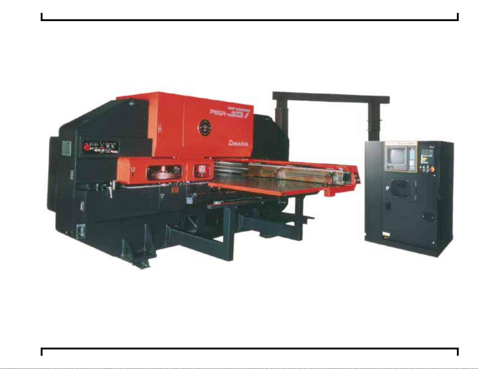
Pega 357 With 04PC Machine Programming Limits
Amada America Inc.
7025 Firestone Blvd.
Buena Park, CA 90621
Phone: 714-739-2111
Fax: 714-739-4099
Email Info@amada.com
Print Date 03/02/2001 Revision 4.0 Page 1 of 12
Page 2

Pega 357 With 04PC Machine Programming Limits ©Amada America, Inc.
Table of Contents
Programmable Travel Limits............................................................................................................................................................3
Machine Speeds ..............................................................................................................................................................................4
Axis Speed in Punching Mode.....................................................................................................................................................4
Hit Rate........................................................................................................................................................................................4
Turret Rotation Speed..................................................................................................................................................................4
Auto Index Speed ........................................................................................................................................................................4
Punch Confirmation Area / Punching Dead Zone.............................................................................................................................5
Definitions....................................................................................................................................................................................5
Punch Confirmation Area.............................................................................................................................................................6
Punching Dead Zone...................................................................................................................................................................7
Material Clamp Locations.................................................................................................................................................................8
Reposition Limitations......................................................................................................................................................................9
Work Chute / Trap Door.................................................................................................................................................................10
58 Station 2 Auto Index Thick Turret..............................................................................................................................................11
44 Station 2 Auto Index Thick Turret..............................................................................................................................................12
Print Date 03/02/2001 Revision 4.0 Page 2 of 12
Page 3
Pega 357 With 04PC Machine Programming Limits ©Amada America, Inc.
Programmable Travel Limits
Track 100
Y
Track 200
Track 300
X
Y-axis Movable Distance By Track Numbers
Origin Statement
X-axis Origin
Movable Distance
Y-axis Origin
X-axis
Inner Track
100 Stations
Center Track
200 Stations
Outer Track
300 Stations
72.000" 50.000" -.400" to 72.400" 1.175" to 51.575" -.400" to 50.000" -1.975" to 48.425"
Print Date 03/02/2001 Revision 4.0 Page 3 of 12
Page 4

Pega 357 With 04PC Machine Programming Limits ©Amada America, Inc.
Machine Speeds
Axis Speed in Punching Mode
F1 = X1,968. IPM Y1,968. IPM
F2 = X1,476. IPM Y1,476. IPM
F3 = X984. IPM Y984. IPM
F4 = X492. IPM Y492. IPM
Hit Rate
200 Hits Per Minute on 1” centers
350 Hits Per Minute in Nibble mode
Turret Rotation Speed
30 RPM
Auto Index Speed
Rotation Speed 60 RPM
5° maximum rotation in nibble mode
Print Date 03/02/2001 Revision 4.0 Page 4 of 12
Page 5

Pega 357 With 04PC Machine Programming Limits ©Amada America, Inc.
Punch Confirmation Area / Punching Dea d Z one.
Definitions
Confirmation Zone = An area that when the confirmation switch is in the on position or it is the first run of the part program
the operator must confirm the punch by pressing the confirmation pushbutton.
Punch Dead Zone = An area within the Confirmation Zone that when the confirmation switch is in the on position or it is
the first run of the part program the operator must confirm the punch by pressing the confirmation
pushbutton. Punching in this area with standard tools may damage the material, material clamp, tool,
other machine components, and may cause operator injury.
Print Date 03/02/2001 Revision 4.0 Page 5 of 12
Page 6

Pega 357 With 04PC Machine Programming Limits ©Amada America, Inc.
Punch Confirmation Area
Track 100 Punch Confirmation Zone
Track 200 Punch Confirmation Zone
Track 100
6.6"
Track 300 Punch Confirmation Zone
Track 200
5.1"
Track 300
3.5"
6.9" 6.9"
Punch Confirmation Zones are set by
mechanical limit switches and as such may vary
from stated values.
Clamp Centerline
Print Date 03/02/2001 Revision 4.0 Page 6 of 12
Page 7

Pega 357 With 04PC Machine Programming Limits ©Amada America, Inc.
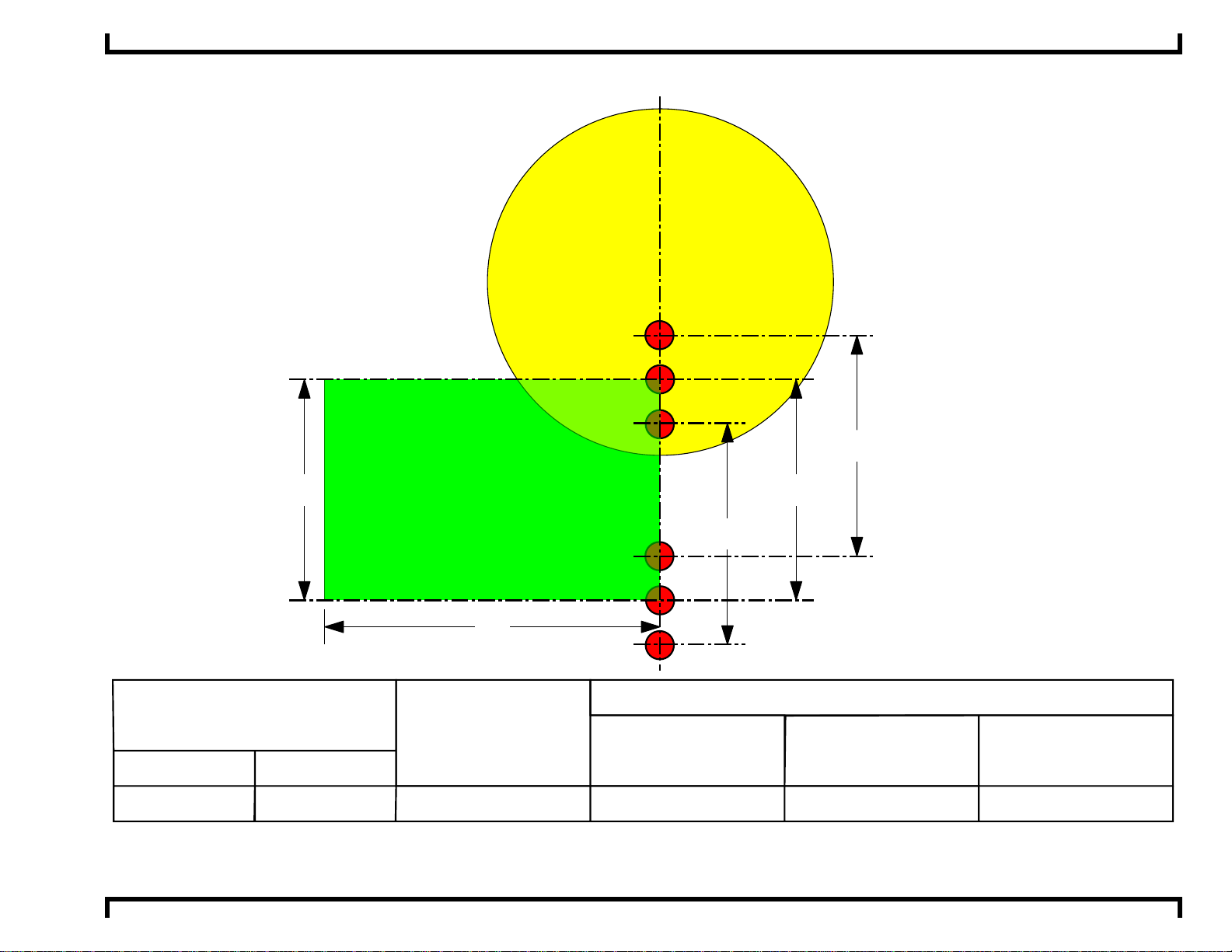
Punching Dead Zone.
T
o
o
l
G
0.400"
T
o
o
l
G
u
d
i
d
e
D
i
r
e
t
e
a
m
a a
1.575"
X- axis Clamp Centerline
"areas where the punch will contact the material clamp"
To the left of the clamp
d
u
i
d
e
D
i
a
m
r
e
t
e
1.575"
a
T
o
o
l
Clamp Sensor
G
u
i
d
b
d
e
D
i
r
a
e
t
m
e
Clamp Dead Zones
are calculated in the following manner.
Clamp position -1.575" - a - d/2
Y 0" Edge of Material
d=
b=
a=
A
B
C
.500"
.500"
1.020"
1.883"
3.500"
X-axis
To the Right of the clamp
Clamp position +1.575" + a + b + d/2
D
4.938"
Station Size
Y-axis
.400" + a + d/2
E
6.250"
Print Date 03/02/2001 Revision 4.0 Page 7 of 12
Page 8

Pega 357 With 04PC Machine Programming Limits ©Amada America, Inc.
Material Clamp Locations
0.400"
Material Clamp
Centerline
Minimum
3.000"
1.575"
1.575"
Material Clamp
1
5.525"
Mimimum Spacing
Clamp Sensor
Material Clamp
Centerline
Mimimum Spacing
Material Clamp
Optional
5.525"
Clamp Sensor
Material Clamp
Centerline
Maximum
69.000"
Y 0" Edge of Material
Clamp Sensor
Material Clamp
Last
Print Date 03/02/2001 Revision 4.0 Page 8 of 12
Page 9

Pega 357 With 04PC Machine Programming Limits ©Amada America, Inc.
Reposition Limitations
When reposi tioning within a Confirmati on zone the Confirmation Button must be pressed to initiate the reposition cycle , as the
material clamps could collide with the repositioning cylinders.
Y
Left
Holddown
2"
X
15.75"
Holddown
100
2"
200
300
15.75"
Track 200 Confirmation Zone 5.1"
Track 300
Confirmation Zone 3.6"
Right
Track 100
Confirmation Zone 6.7"
Print Date 03/02/2001 Revision 4.0 Page 9 of 12
Page 10

Pega 357 With 04PC Machine Programming Limits ©Amada America, Inc.
Work Chute / Trap Door
Work Chute / Trap door only available on ball transfer table equipped machines.
Track 100
Track 200
Track 300
2.375"
Turret Disk
Work Chute / Trap Door
7.9"
7.9"
Print Date 03/02/2001 Revision 4.0 Page 10 of 12
Page 11

Pega 357 With 04PC Machine Programming Limits ©Amada America, Inc.
58 Station 2 Auto Index Thick Turret
This turret used on the following machine models
333
331
230
129
228
A/I
220
2
19
132
336
235
134
58 STATION
1000
237
mm disc
239
138
340
141
342
143
244
345
1
246
47
9
34
2
48
3
51
1
50
53
2
1
52
2
PEGA 345, PEGA 345 King, PEGA 357, PEGA 367
COMA 555, COMA 557, COMA 567, COMA 588
VIPROS 345, VIPROS 357, VIPROS 367
VIPROS 357 Queen, VIPROS 367 Queen
3
54
55
2 AUTO INDEX
6
11
2
17
3
18
4
11
3
15
111
2
12
3
13
2
10
1
07
2
08
9
30
Print Date 03/02/2001 Revision 4.0 Page 11 of 12
306
1
05
102
2
03
304
2
01
A/I
2
56
MAXIMUM SIZE
ROUND
2
64
1
65
1
68
1
70
2
71
3
69
3
72
2
66
3
67
AUTO INDEX
1/2" ( 12.7mm )
A
1 1/4" ( 31.7mm )
B
C
D
E
B
2" ( 50.8mm )
3 1/2" ( 88.9mm )
4 1/2" ( 114.3mm )
1 1/4" ( 31.7mm )
NUMBER OF
STATIONS
( KEYED )
36 ( 12 )
12 ( 12 )
4 ( 4 )
2 ( 2 )
2 ( 2 )
2 ( 2 )
Page 12

Pega 357 With 04PC Machine Programming Limits ©Amada America, Inc.
44 Station 2 Auto Index Thick Turret
E
B
A
C
223
B
216
A/I
D
215
113
314
B
B
312
310
A
111
108
209
207
C
A
326
225
205
306
328
124
104
303
B
229
127
1000mm Disc Thick
44 Station
2 Auto Index
102
201
E
130
155
331
132
152
253
356
B
334
233
354
B
A
251
A
235
A/I
C
237
136
139
141
244
C
This turret used on the following machine models
Pega 344, 345Q, 345K, 357, 367
Coma 555, 557, 567, 588
Vipros 345, 357, 367
A
338
340
B
342
243
B
B
D
Vela II 355
MAXIMUM
SIZE ROUND
NUMBER OF
STATIONS
(KEYED)
A
B
C
D
E
B
½"
1¼"
2"
3½"
4½"
1¼"
12.7mm
31.7mm
50.8mm
88.9mm
114.3mm
31.7mm
18 (6)
16 (16)
4 (4)
2 (2)
2 (2)
2 (2)AUTO INDEX
Print Date 03/02/2001 Revision 4.0 Page 12 of 12
 Loading...