


QUICKSTART GUIDE
ENGLISH ( 2 – 4 )
MANUAL DE INICIO RÁPIDO
ESPAÑOL ( 5 – 7 )
GUIDE D’UTILISATION RAPIDE
FRANÇAIS ( 8 – 10 )
GUIDA RAPIDA
ITALIANO ( 11 – 13 )
KURZANLEITUNG
DEUTSCH ( 14 – 16 )
SNELSTARTGIDS
NEDERLANDS ( 17 – 19 )

BOX CONTENTS
yMIXPACK Express
yPower cable
yQuickstart Guide
ySafety Instructions & Warranty Information booklet
CONNECTION DIAGRAM
Power
Microphones*
Headphones*
Speaker |
Speaker |
Footswitch*
Drum Machine*
*not included
Notes:
yMicrophones, headphones, drum machine, footswitch, etc. are not included.
yTo reduce electrical hum at high gain settings, keep the mixer's power supply away from your cables and the mixer's channel inputs.
2

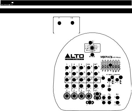
FEATURES
1.POWER IN – Use the included
power cable to connect the mixer
to a power outlet. While the 2 1 power is switched off, plug the
power cable into the mixer first, then plug the power cable into a power outlet.
2.POWER SWITCH – Turns the
|
mixer on and off. Turn on the |
|
|
mixer after all input devices have |
18 |
|
been connected. Make sure the |
|
|
MASTER LEVEL knob is set to |
19 |
|
"zero" before turning it on. |
|
3. |
MIC INPUT (XLR / 1/4") – |
|
|
Connect a microphone to these |
20 |
|
inputs with an XLR or 1/4" cable. |
|
4. |
MIC INPUT (XLR) – Connect a |
|
|
|
|
|
|
|
|
|||
|
microphone to these inputs with |
|
|
|
|
|
|
|
|
|||
|
an XLR cable. |
|
|
|
|
|
|
|
|
|
22 |
|
5. |
LINE INPUT (1/4") |
– |
Connect |
7 |
7 |
7 |
7 |
7 |
|
|
|
|
|
line-level devices to these inputs |
|
|
|
|
|
|
|
|
|||
|
with 1/4" cables. |
|
|
|
8 |
8 |
8 |
8 |
8 |
|
|
|
|
|
|
|
|
|
|
|
|||||
6. |
LINE INPUT (RCA) |
– |
Connect |
|
|
|
|
|
26 |
25 |
25 |
|
|
line-level devices to |
these inputs |
|
|
|
|
|
|||||
|
9 |
9 |
9 |
9 |
9 |
23 |
24 |
|||||
|
with a standard stereo RCA cable. |
|
||||||||||
|
|
|
|
|
|
|
|
|
||||
7. |
HI EQ (TREBLE) – Adjusts |
the |
10 |
10 |
10 |
10 |
10 |
14 |
|
|
||
|
high (treble) frequencies of the |
|
|
|||||||||
|
|
|
|
|
|
|
|
|
||||
|
channel. |
|
|
|
|
|
|
|
|
|
15 |
|
8. |
LOW EQ (BASS) – Adjusts the |
|
|
|
|
6 |
|
|
|
|||
|
low (bass) frequencies |
of |
the |
3 |
3 |
3 |
|
|
|
|
||
|
41 |
|
|
|
|
|||||||
|
|
|
|
|
|
|
|
NEW |
|
|
|
|
|
channel. |
|
|
|
|
|
|
|
11 |
12 |
17 |
16 |
9. |
FX AUX1 POST – Adjusts |
the |
|
|
|
5 |
|
13 |
21 |
16 |
||
|
channel audio (post-EQ) level that |
|
|
|
|
|||||||
|
|
|
|
|
|
|
|
|
||||
|
is sent to the mixer's internal |
|
|
|
|
|
|
|
|
|||
|
effects processor and FX SEND. |
|
|
|
|
|
|
|
|
|||
|
Turn this up for the channels that |
|
|
|
|
|
|
|
|
|||
|
you want internal effects applied to. You can use this to apply effects to individual channels. |
|
|
|||||||||
10.CHANNEL LEVEL – Adjusts the audio level on the channel.
11.TAPE OUT – You can use a standard stereo RCA cable to connect this output to an external recording device. The signal sent out these RCA outputs is the same as the MAIN OUT signal.
12.FX SEND OUTPUT – You can use a 1/4" TRS cable to connect this output to the input of an external amplifier or active monitor to create a custom monitor mix for onstage musicians. You can adjust this level with the FX AUX1 POST knob. To use an external effects rack unit, compressor, etc. with the mixer, you can use Y-cables to connect this output to the input of your external device, then connect the outputs of the device to the FX RETURN input.
13.FX RETURN INPUT – You can connect the output of an external device to this input with a 1/4" mono cable. This is usually used for outboard effects devices but can also be used like an extra input channel for synthesizers, drum machines, etc. Adjust this input's volume with the FX RET knob.
14.FX RET – Adjusts the volume of the signal being sent into the FX RETURN INPUT and routed to the MAIN OUT.
15.MONITOR OUT – Use a standard 1/4" cable to connect this output to your monitor or amplifier system. The level of this output is controlled by the MONITOR LEVEL knob.
16.MAIN OUT – Use standard 1/4" cables to connect these outputs to the speakers. The level of these outputs is controlled by the MASTER LEVEL knob.
17.PHONES – Connect your 1/4" stereo headphones to this output. The MONITOR LEVEL knob controls the volume.
18.FX CLIP/MUTE LED – The LED will flash if the mixer's internal effects processor signal is clipping. If this happens, decrease the setting of the FX AUX1 POST knob or CHANNEL LEVEL knob.
19.EFFECTS SELECTOR – Selects the effect that the mixer's internal effects processor will apply to the various channels. Each channel can send different levels of audio to the processor by adjusting their FX AUX1 POST knobs. See the EFFECTS section for an explanation of the available effects.
20.EFFECTS ON / OFF – Press this button to mute/unmute the effects.
21.FOOTSWITCH – When a latching-style footswitch is connected to this jack with a 1/4" TRS cable, it can be pressed to allow all channels to bypass the mixer's internal effects processor.
22.GRAPHIC EQUALIZER – You can use these controls to adjust the equalization of the main mix.
23.MONITOR LEVEL – Adjusts the volume of the MONITOR OUT and your headphones.
24.MASTER LEVEL – Adjusts the volume of the MAIN OUT.
25.LED METERS – Shows the audio level of the main mix and monitor mix. Turn the volume down if the +10 LED lights up excessively.
26.POWER LED – Illuminates when the mixer is on.
3

EFFECTS
TO HEAR THE EFFECTS ON A CHANNEL: Use the EFFECTS SELECTOR to choose one of the effects below, then turn up the FX AUX1 POST for that channel.
# |
|
PRESET |
|
DESCRIPTION |
|
PARAMETER |
1 |
|
VOCAL 1 |
Reverb, simulating a room without delay time. |
|
Decay time: 450 ms |
|
|
|
Pre-delay: 0 ms |
||||
|
|
|
|
|
|
|
|
|
|
|
|
|
|
2 |
|
VOCAL 2 |
Reverb, simulating a room with a small delay time. |
|
Decay time: 240 ms |
|
|
|
Pre-delay: 25 ms |
||||
|
|
|
|
|
|
|
|
|
|
|
|
|
|
3 |
|
VOCAL 3 |
|
Reverb, simulating a small space with a slight decay |
|
Decay time: 100 ms |
|
|
time. |
|
Pre-delay: 114 ms |
||
|
|
|
|
|
||
|
|
|
|
|
|
|
4 |
|
BRIGHT HALL |
|
Reverb, simulating a large acoustic space. |
|
Decay time: 290 ms |
|
|
|
Pre-delay: 23 ms |
|||
|
|
|
|
|
|
|
|
|
|
|
|
|
|
5 |
|
WARM HALL |
Reverb, simulating the acoustics of a stage space. |
|
Decay time: 360 ms |
|
|
|
Pre-delay: 45 ms |
||||
|
|
|
|
|
|
|
|
|
|
|
|
|
|
6 |
|
BRIGHT ROOM |
|
Reverb, simulating a studio with many early reflections. |
|
Decay time: 210 ms |
|
|
|
Pre-delay: 23 ms |
|||
|
|
|
|
|
|
|
|
|
|
|
|
|
|
7 |
|
WARM ROOM |
|
Reverb, simulating a bright studio room. |
|
Decay time: 210 ms |
|
|
|
Pre-delay: 45 ms |
|||
|
|
|
|
|
|
|
|
|
|
|
|
|
|
8 |
|
PLATE |
|
Simulates bright plate reverb. |
|
Decay time: 290 ms |
|
|
|
Pre-delay: 10 ms |
|||
|
|
|
|
|
|
|
|
|
|
|
|
|
|
9 |
|
STEREO DELAY |
|
Reproduces the signal after a small period of time with a |
|
Delay period: 352 ms |
|
|
slight difference between the two stereo channels. |
|
|||
|
|
|
|
|
|
|
|
|
|
|
|
|
|
10 |
|
STEREO DELAY 2 |
|
Reproduces the signal after a small period of time with a |
|
Delay period: 238 ms |
|
|
slight difference between the two stereo channels. |
|
|||
|
|
|
|
|
|
|
|
|
|
|
|
|
|
11 |
|
REVERB+DELAY 1 |
Delay effect with room reverb. |
|
Delay period: 326 ms |
|
|
|
Reverse decay time: 290 ms |
||||
|
|
|
|
|
|
|
|
|
|
|
|
|
|
12 |
|
REVERB+DELAY 2 |
Delay effect with room reverb. |
|
Delay period: 211 ms |
|
|
|
Reverse decay time: 240 ms |
||||
|
|
|
|
|
|
|
|
|
|
|
|
|
|
13 |
|
REVERB+DELAY 3 |
Delay effect with room reverb. |
|
Delay period: 375 ms |
|
|
|
Reverse decay time: 210 ms |
||||
|
|
|
|
|
|
|
|
|
|
|
|
|
|
14 |
|
REVERB+DELAY 4 |
Delay effect with room reverb. |
|
Delay period: 277 ms |
|
|
|
Reverse decay time: 150 ms |
||||
|
|
|
|
|
|
|
|
|
|
|
|
|
|
15 |
|
REVERB+CHORUS |
|
Stereo chorus effect with room reverb. |
|
Chorus rate: 3.67 Hz |
|
|
|
Reverse decay time: 290 ms |
|||
|
|
|
|
|
|
|
|
|
|
|
|
|
|
16 |
|
REVERB+CHORUS 2 |
Stereo chorus effect with room reverb. |
|
Chorus rate: 3.02 Hz |
|
|
|
Reverse decay time: 150 ms |
||||
|
|
|
|
|
|
|
|
|
|
|
|
|
|
4

CONTENIDO DE LA CAJA
yMIXPACK Express
yCable de alimentación
yGuía de inicio rápido
yFolleto de instrucciones de seguridad e información sobre la garantía
DIAGRAMA DE CONEXIÓN
Suministro eléctrico
Micrófonos*
Auriculares*
Altavoce |
Altavoce |
Pedal*
Caja de ritmos*
* no incluido
Notas:
yNo se incluyen micrófonos, auriculares, caja de ritmos, pedal, etc.
yPara reducir el zumbido eléctrico cuando se usan ajustes altos de ganancia, mantenga la fuente de alimentación del mezclador alejada del cable de su guitarra y de las entradas de los canales del equipo.
5
CARACTERÍSTICAS
1.ENTRADA DE ALIMENTACIÓN - Use
el cable de alimentación incluido para |
|
|
|
|
|
||||
conectar |
el |
mezclador |
a |
un |
|
2 |
|
1 |
|
tomacorriente |
alimentado. |
Con |
la |
|
|
|
|
|
|
alimentación |
|
eléctrica desconectada, |
|
|
|
|
|
||
|
|
|
|
|
|
||||
enchufe el cable de alimentación al |
|
|
|
|
|
||||
mezclador primero, y luego al |
|
|
|
|
|
||||
|
|
|
|
|
|||||
tomacorriente. |
|
|
|
|
|
|
|
|
|
2.INTERRUPTOR DE ENCENDIDO –
Se usa para encender y apagar el mezclador. Encienda el mezclador después de haber conectado todos los dispositivos de entrada. Asegúrese de que la perilla de NIVEL MAESTRO esté ajustada a "cero" antes de encenderlo.
3.ENTRADA DE MICRÓFONO (XLR / 1/4") – Conecte a estas entradas un micrófono con un cable XLR o 1/4".
4.ENTRADA DE MICRÓFONO (XLR) –
Conecte a estas entradas un micrófono con un cable XLR.
5.ENTRADA DE LÍNEA (1/4") – Conecte a estas entradas dispositivos de nivel de línea con cables de 1/4”.
6.ENTRADA DE LÍNEA (RCA) –
Conecte a estas entradas los dispositivos de nivel de línea con un cable RCA estéreo estándar.
7.ECUALIZADOR DE ALTOS (AGUDOS) – Ajusta las frecuencias altas (agudos) del canal.
|
|
|
18 |
|
|
|
|
19 |
|
|
|
|
20 |
|
|
|
|
|
22 |
7 |
7 |
7 |
7 |
7 |
8 |
8 |
8 |
8 |
8 |
|
|
|
|
|
|
|
|
26 |
25 |
25 |
9 |
9 |
9 |
9 |
9 |
23 |
24 |
|
10 |
10 |
10 |
10 |
10 |
14 |
|
|
|
|
|
|
|
|
15 |
|
3 |
3 |
3 |
|
6 |
|
|
|
NEW41 |
11 |
12 |
17 |
16 |
|||
|
|
|
5 |
|
13 |
21 |
16 |
8.ECUALIZADOR DE BAJOS (GRAVES) – Ajusta las frecuencias bajas (graves) del canal.
9.POST AUXILIAR 1 DE EFECTOS – Ajusta el nivel de audio del canal (post-ecualización) que se envía al procesador de efectos interno del mezclador y al ENVÍO DE EFECTOS. Aumente el ajuste para los canales a los que desea aplicar efectos internos. Puede usarlo para aplicar efectos a canales individuales.
10.NIVEL DE CANAL – Ajusta el nivel de audio del canal.
11.SALIDA PARA CINTA – Puede usar un cable RCA estéreo estándar para conectar esta salida a un dispositivo de grabación externo. La señal enviada por estas salidas RCA es la misma señal de la SALIDA PRINCIPAL.
12.SALIDA DE ENVÍO DE EFECTOS – Puede usar un cable TRS de 1/4" para conectar esta salida a la entrada de un amplificador externo o monitor activo a fin de crear una mezcla de monitor personalizada para los músicos en el escenario. Puede ajustar este nivel con la perilla POST AUXILIAR 1 DE EFECTOS. Para usar una unidad de rack de efectos, compresor, etc. externos con el mezclador, puede usar cables en “Y” a fin de conectar esta salida a la entrada de su dispositivo externo y luego conectar las salidas de este último a la entrada de RETORNO DE EFECTOS.
13.RETORNO AUXILIAR 1 – Puede conectar a estas entradas las salidas de un dispositivo externo con un cable mono de 1/4". Esto se usa habitualmente para dispositivos de efectos externos, pero se puede usar también como canal de entrada adicional para sintetizadores, baterías electrónicas, cajas de ritmo, etc. Ajuste el volumen de esta entrada con la perilla de RETORNO DE EFECTOS.
14.RETORNO DE EFECTOS – Ajusta el volumen de la señal que se envía a la ENTRADA DE RETORNO DE EFECTOS y se aplica a la SALIDA PRINCIPAL.
15.SALIDA PARA MONITOR – Use un cable estándar de 1/4" para conectar esta salida al sistema de amplificador o monitor. El nivel de esta señal de salida está controlado por la perilla de NIVEL DEL MONITOR.
16.SALIDAS DE MEZCLA PRINCIPAL – Use cables estándar TRS de 1/4" para conectar estas salidas a los altavoces. El nivel de estas salidas está controlado por la perilla MASTER LEVEL.
17.AURICULARES – Conecte sus auriculares estéreo de ¼” a esta salida. La perilla MONITOR LEVEL controla el volumen.
18.LED DE FX CLIP/MUTE – El LED destella si la señal del procesador de efectos interno del mezclador se está recortando. Si esto sucede, disminuya el ajuste de la perilla FX AUX1 POST o la perilla de volumen CHANNEL LEVEL (Canal) .
19.SELECTOR DE EFECTOS – Selecciona el efecto que el procesador de efectos interno del mezclador aplica a los diversos canales. Cada canal puede enviar al procesador niveles diferentes de audio ajustando sus perillas FX AUX1 POST. Consulte en la sección EFECTOS una explicación de los efectos disponibles.
20.ACTIVACIÓN / DESACTIVACIÓN DE EFECTOS – Pulse este botón para silenciar/anular el silenciamiento de los efectos.
21.INTERRUPTOR DE PEDAL – Cuando se conecta a este conector un interruptor de pedal de tipo de enganche con un cable TRS de 1/4", se puede presionar para permitir que todos los canales puenteen el procesador de efectos interno del mezclador.
6
 Loading...