


FOR CAR USE ONLY/NUR FÜR AUTOMOBIL GEBRAUCH/POUR APPLICATION AUTOMOBILE UNIQUEMENT/PARA USO EN AUTOMÓVILES/SOLO PER L’UTILIZZO IN AUTOMOBILE/ENDAST FÖR BILBRUK/ALLEEN VOOR GEBRUIK IN DE AUTO/ТОЛЬКО ДЛЯ ИСПОЛЬЗОВАНИЯ В АВТОМОБИЛЯХ/DO UŻYCIA TYLKO W SAMOCHODZIE
EN
8-INCH ADVANCED NAVI STATION
X803D-U
7-INCH ADVANCED NAVI STATION
INE-W720D
•INSTALLATION MANUAL
•INSTALLATIONSANLEITUNG
•GUIDE D’INSTALLATION
•MANUAL DE INSTALACIÓN
•MANUALE DI INSTALLAZIONE
•INSTALLATIONSHANDBOK
•INSTALLATIEHANDLEIDING
•РУКОВОДСТВО ПО УСТАНОВКЕ
•INSTRUKCJA MONTAŻU
DE
FR
ES
IT
SE
NL
RU
ALPINE ELECTRONICS MARKETING, INC. |
ALPINE ELECTRONICS GmbH |
ALPINE ITALIA S.p.A. |
1-7, Yukigaya-Otsukamachi, Ota-ku, |
Ohmstraße 4 |
Viale Cristoforo Colombo, 8 |
Tokyo 145-0067, JAPAN |
85716 Unterschleißheim, Germany |
20090 Trezzano sul Naviglio MI, Italy |
Phone: 03-5499-4531 |
Phone: 089-32 42 640 |
Phone +39 02 484781 |
ALPINE ELECTRONICS OF AMERICA, INC. |
ALPINE ELECTRONICS OF U.K., LTD. |
ALPINE ELECTRONICS DE ESPAÑA, S.A. |
1500 Atlantic Blvd, |
Alpine House |
Portal de Gamarra 36, Pabellón, 32 |
Auburn Hills, Michigan 48326 U.S.A. |
Fletchamstead Highway, Coventry CV4 9TW, U.K. |
01013 Vitoria (Alava)-APDO 133, Spain |
Phone 1-800-ALPINE-1 (1-800-257-4631) |
www.alpine.co.uk |
Phone 945-283588 |
PL
ALPINE ELECTRONICS OF AUSTRALIA PTY. LIMITED |
ALPINE ELECTRONICS FRANCE S.A.R.L. |
161-165 Princes Highway, Hallam |
184 allée des Erables |
Victoria 3803, Australia |
CS 52016 – Villepinte |
Phone 03-8787-1200 |
95 945 Roissy CDG cedex |
|
FRANCE |
|
Phone : + 33(0)1 48 63 89 89 |
YAMAGATA (THAILAND) Co., Ltd.
324 Moo 4, Bangpoo Industrial Estate Soi6, Sukhumvit Road T.Phraeksa,
A.Muang Samutprakarn, Samutprakarn 10280, Thailand
Designed by ALPINE Japan Printed in Thailand (Y) 68-38492Z08-A (Y-B5)

ENGLISH
Contents |
|
WARNING ...................................................... |
2 |
CAUTION ....................................................... |
2 |
Precautions ................................................... |
3 |
Accessory List ........................................................ |
3 |
Installation .............................................................. |
3 |
Caution concerning the installation |
|
location ............................................................ |
3 |
Mounting the GPS Antenna inside the |
|
vehicle .............................................................. |
3 |
Mounting the Microphone ............................... |
4 |
Installation example using the Original |
|
Mounting Bracket .......................................... |
4 |
Connections ........................................................... |
5 |
If an ACC power supply is not available ........ |
8 |
System Example ..................................................... |
9 |
1-EN

 WARNING
This symbol means important instructions. Failure to heed them can result in serious injury or death.
DO NOT DISASSEMBLE OR ALTER.
Doing so may result in an accident, fire or electric shock.
KEEP SMALL OBJECTS SUCH AS SCREWS OUT OF THE REACH OF CHILDREN.
Swallowing them may result in serious injury. If swallowed, consult a physician immediately.
USE THE CORRECT AMPERE RATING WHEN REPLACING FUSES.
Failure to do so may result in fire or electric shock.
DO NOT BLOCK VENTS OR RADIATOR PANELS.
Doing so may cause heat to build up inside and may result in fire.
USE THIS PRODUCT FOR MOBILE 12V APPLICATIONS.
Use for other than its designed application may result in fire, electric shock or other injury.
MAKE THE CORRECT CONNECTIONS.
Failure to make the proper connections may result in fire or product damage.
USE ONLY IN CARS WITH A 12 VOLT NEGATIVE GROUND.
(Check with your dealer if you are not sure.) Failure to do so may result in fire, etc.
BEFORE WIRING, DISCONNECT THE CABLE FROM THE NEGATIVE BATTERY TERMINAL.
Failure to do so may result in electric shock or injury due to electrical shorts.
DO NOT ALLOW CABLES TO BECOME ENTANGLED IN SURROUNDING OBJECTS.
Arrange wiring and cables in compliance with the manual to prevent obstructions when driving. Cables or wiring that obstruct or hang up on places such as the steering wheel, shift lever, brake pedals, etc. can be extremely hazardous.
DO NOT SPLICE INTO ELECTRICAL CABLES.
Never cut away cable insulation to supply power to other equipment. Doing so will exceed the current carrying capacity of the wire and result in fire or electric shock.
DO NOT DAMAGE PIPE OR WIRING WHEN DRILLING HOLES.
When drilling holes in the chassis for installation, take precautions so as not to contact, damage or obstruct pipes, fuel lines, tanks or electrical wiring. Failure to take such precautions may result in fire.
DO NOT USE BOLTS OR NUTS IN THE BRAKE OR STEERING SYSTEMS TO MAKE GROUND CONNECTIONS.
Bolts or nuts used for the brake or steering systems (or any other safety-related system), or tanks should NEVER be used for installations or ground connections. Using such parts could disable control of the vehicle and cause fire etc.
DO NOT INSTALL IN LOCATIONS WHICH MIGHT HINDER VEHICLE OPERATION, SUCH AS THE STEERING WHEEL OR SHIFT LEVER.
Doing so may obstruct forward vision or hamper movement etc. and results in serious accident.
DO NOT INSTALL THE MONITOR NEAR THE PASSENGER SEAT AIR BAG.
If the unit is not installed correctly the air bag may not function correctly and when triggered the air bag may cause the monitor to spring upwards causing an accident and injuries.
 CAUTION
This symbol means important instructions. Failure to heed them can result in injury or material property damage.
HAVE THE WIRING AND INSTALLATION DONE BY EXPERTS.
The wiring and installation of this unit requires special technical skill and experience. To ensure safety, always contact the dealer where you purchased this product to have the work done.
USE SPECIFIED ACCESSORY PARTS AND INSTALL THEM SECURELY.
Be sure to use only the specified accessory parts. Use of other than designated parts may damage this unit internally or may not securely install the unit in place. This may cause parts to become loose resulting in hazards or product failure.
ARRANGE THE WIRING SO IT IS NOT CRIMPED OR PINCHED BY A SHARP METAL EDGE.
Route the cables and wiring away from moving parts (like the seat rails) or sharp or pointed edges. This will prevent crimping and damage to the wiring. If wiring passes through a hole in metal, use a rubber grommet to prevent the wire’s insulation from being cut by the metal edge of the hole.
DO NOT INSTALL IN LOCATIONS WITH HIGH MOISTURE OR DUST.
Avoid installing the unit in locations with high incidence of moisture or dust. Moisture or dust that penetrates into this unit may result in product failure.
2-EN

Precautions
•Be sure to disconnect the cable from the (–) battery post before installing your unit. This will reduce any chance of damage to the unit in case of a short-circuit.
•Be sure to connect the colour coded leads according to the diagram. Incorrect connections may cause the unit to malfunction or damage to the vehicle’s electrical system.
•When making connections to the vehicle’s electrical system, be aware of the factory installed components (e.g. on-board computer). Do not tap into these leads to provide power for this unit. When connecting the unit to the fuse box, make sure the fuse for the intended circuit of the unit has the appropriate amperage. When in doubt, consult your Alpine dealer.
•The unit uses female RCA-type jacks for connection to other units (e.g. amplifier) having RCA connectors. You may need an adaptor to connect other units. If so, please contact your authorized Alpine dealer for assistance.
•Be sure to connect the speaker (–) leads to the speaker (–) terminal. Never connect left and right channel speaker cables to each other or to the vehicle body.
Accessory List |
|
|
• |
X803D-U or INE-W720D............................................................................. |
1 |
• |
Power cable.................................................................................................... |
1 |
• |
GPS Antenna.................................................................................................. |
1 |
• |
Antenna mounting plate........................................................................... |
1 |
• Cable clamp for antenna ..................................................................... |
1set |
|
• |
USB extension cable.................................................................................... |
1 |
• |
PRE OUT cable ............................................................................................... |
1 |
• |
Microphone.................................................................................................... |
1 |
• |
CAN I/F cable ................................................................................................. |
1 |
• |
W.REMOTE cable........................................................................................... |
1 |
• Face plate (INE-W720D only).................................................................... |
1 |
|
• |
HDMI Fixation Bracket................................................................................ |
1 |
• Flush head screw (M5×8) .......................................................................... |
4 |
|
• |
Screw (M5×8)................................................................................................. |
4 |
• |
Owner’s Manual...................................................................................... |
1set |
Installation
X803D-U user
To install the X803D-U, refer to the manual in the separately purchased installation kit for each car type.
Caution
Do not block the unit’s fan, thus preventing air circulation. If blocked, heat will accumulate inside the unit and may cause a fire.
<example>
Air ventilation hole
Rear of the Unit
Caution concerning the installation location
Angle of installation
Install at an angle between horizontal and 30°. Note that installing at an angle outside of this range will result in a loss of performance and possibly damage.
0 - 30°
Mounting the GPS Antenna inside the vehicle
1Clean the mounting location.
2Put on the GPS Antenna mounting plate.
3Mount the GPS Antenna.
GPS Antenna
Antenna mounting plate
This unit
•Do not mount the GPS Antenna inside the centre console.
-Mount the GPS Antenna on a flat plane of the dash board or rear tray.
-Make sure the GPS Antenna is not covered (obstructed) by any metallic surface or object.
•If the GPS Antenna is mounted near the unit, the reception becomes poor, and the location of your vehicle may not be displayed correctly.
-Mount the GPS Antenna far away enough from the unit.
-Bundle the GPS Antenna cable away from the rear of the unit.
•Some thermal reflection type or thermal absorption type glass may interrupt high frequency waves. If reception is poor with the antenna installed inside the car, try to mount the antenna outside the car.
3-EN

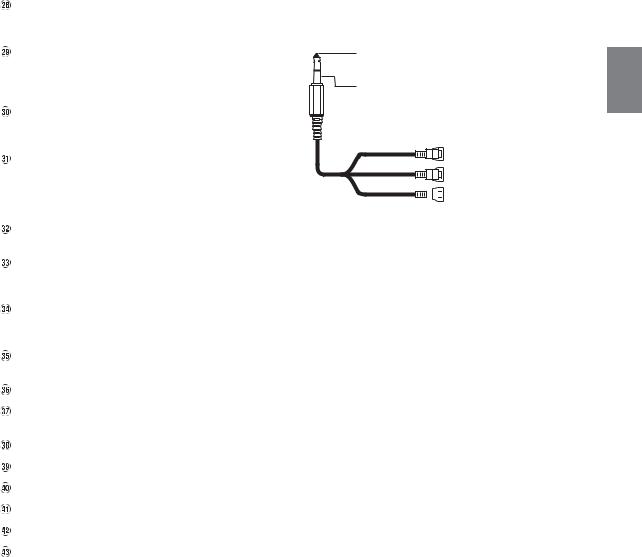
Mounting the Microphone
For safe use, make sure of the following:
•Location is stable and firm.
•Driver’s view and operations are not obstructed.
•Microphone is located where the driver’s voice can be easily picked up (for example, on the sun visor).
When you speak into the microphone, you should not have to change your driving posture. This may cause a distraction, taking your attention away from safely driving your vehicle. Carefully consider direction and distance while mounting the microphone. Confirm that the driver’s voice can be easily picked up at the selected location.
Microphone
Cable clamp (Sold separately)
Installation example using the Original Mounting Bracket
1Mount the original mounting bracket to the unit using the supplied screws.
Ground Lead*
Chassis
Original Mounting Bracket
Screws (M5 × 8) (Included)
Face plate (Included)
*To securely connect the ground lead, use an already installed screw on a metal part of the vehicle (marked ( )) or a clean, bare metal spot on the vehicle’s chassis.
2Connect all other leads of the unit according to details described in the “Connections” (page 5).
3Mounting the unit in a car.
•Fix the cables carefully. Do not damage them by tucking them into movable parts, such as a seat rail, or by locating them against sharp or pointed edges.
Note on using HDMI Connection Cables
When using HDMI connection cables, secure the cables to the HDMI Terminals with the supplied HDMI Fixation Bracket.
1Slide the HDMI Fixation Bracket into the grooves (A).
2Secure it with the screw (B).
HDMI Terminal
(A) |
(A) |
HDMI Fixation Bracket
(Included)
(B)
4-EN

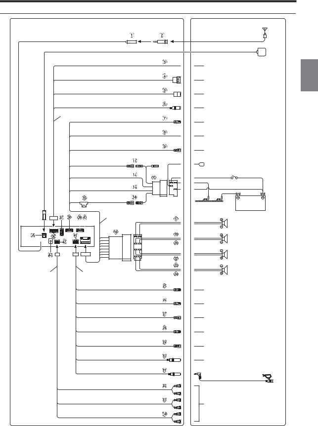
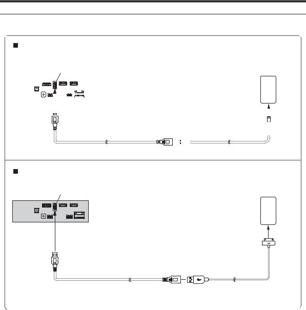
Connections
Antenna
|
ISO Antenna Plug |
|
|
GPS Antenna (Included) |
|
SPEED SENSOR |
To the vehicle speed pulse line |
|
(Green/White) |
||
|
||
CAMERA |
To Front or Rear camera |
|
|
||
CONNECT2 I/F |
To CAN Interface box |
|
|
||
AUX INPUT |
To AUX output device |
|
|
||
CAN I/F cable |
|
|
REMO |
To amplifier or equalizer |
|
(Blue/White) |
||
|
||
REVERSE |
To plus side of the back lamp signal |
|
(Orange/White) |
lead of the car |
|
PARKING BRAKE |
To the parking brake signal lead |
|
(Yellow/Blue) |
||
|
||
ACC |
To power antenna or Rear Camera |
|
Cover |
||
(Red) |
||
|
||
GND |
|
|
(Black) |
Ignition key |
|
P. ANT |
|
|
(Blue) |
|
|
BATT |
Battery |
|
(Yellow) |
||
|
||
Power cable |
(Green) |
|
|
||
|
Rear Left |
|
|
(Green/Black) |
|
|
(White) |
|
|
Front Left |
|
|
(White/Black) |
|
|
Speakers |
|
|
(Grey/Black) |
|
|
Front Right |
|
|
(Grey) |
|
|
(Violet/Black) |
PRE OUT cable |
W.REMOTE cable |
(Violet) |
DVD REMOTE
(Brown) MON REMOTE
(Brown) REMOTE IN
(Brown/White) REMOTE OUT
(Brown)
DVD STATUS IN
(Red/White) STEERING REMOTE
Rear Right
To remote control input lead of
DVE-5300
To remote control input lead of Rear Monitor
To remote control output lead
To remote control input lead
To remote control output lead of DVE-5300
To steering remote control interface box
MIC IN
SUBW
FRONT OUT
REAR OUT
Microphone (Included)
To input terminal of amplifier when adding an external amplifier
5-EN

Radio Antenna Receptacle
ISO/JASO Antenna Adapter (sold separately)
ISO/JASO Antenna Adapter may be required, depending on the vehicle.
Speed Sensor Lead (Green/White)
Improper connection of the speed pulse line may cause important safety features of the vehicle to fail (such as the brakes or air bags). Such failures may result in an accident and loss of life. We strongly recommend that the installation be performed by a trained, authorized Alpine dealer.
Direct CAMERA Input Connector
Use when the optional direct camera is connected.
CAN Interface Connector
To CAN Interface box
AUX Input Connector
Input lead for AUX video/audio signal.
•A separately sold AV/RCA interface cable (4-pole mini AV plug to 3-RCA) is required. For details on using an AV/RCA interface cable (4-pole mini AV plug to 3-RCA), see “Usable AV/RCA Interface Cable (4-pole mini AV plug to 3-RCA)” (page 7).
Remote Turn-On Lead (Blue/White)
Connect this lead to the remote turn-on lead of your amplifier or signal processor.
Reverse Lead (Orange/White)
Connect to the plus side of the car’s reverse lights. These lights illuminate when the transmission is shifted into reverse (R). With this lead properly wired, the video picture automatically switches to the rear camera whenever the car is put into reverse
(R).
Parking Brake Lead (Yellow/Blue)
Connect this lead to the power supply side of parking brake switch to transmit the parking brake status signals to the unit.
ISO Power Supply Connector
Switched Power Lead (Ignition) (Red)
Connect this lead to an open terminal on the vehicle’s fuse box or another unused power source that provides (+) 12V only when the ignition is turned on or in the accessory position.
Ground Lead (Black)
Connect this lead to a good chassis ground on the vehicle. Make sure the connection is made to bare metal and is securely fastened using the sheet metal screw provided.
Power Antenna Lead (Blue)
Connect this lead to the +B terminal of your power antenna, if applicable.
•When your vehicle’s Rear view camera is equipped with an electric protective cover, change the setting of Rear Camera Cover to On and connect this lead to the +B terminal of your Rear view camera cover.
•This lead should be used only for controlling the vehicle’s power antenna or Rear view camera cover. Do not use this lead to turn on an amplifier or a signal processor, etc.
Battery Lead (Yellow)
Connect this lead to the positive (+) post of the vehicle’s battery.
Fuse Holder (15A)
ISO Connector (Speaker Output)
Left Rear (+) Speaker Output Lead (Green)
Left Rear (–) Speaker Output Lead (Green/Black) Left Front (+) Speaker Output Lead (White)
Left Front (–) Speaker Output Lead (White/Black) Right Front (–) Speaker Output Lead (Grey/Black) Right Front (+) Speaker Output Lead (Grey)
Right Rear (–) Speaker Output Lead (Violet/Black) Right Rear (+) Speaker Output Lead (Violet)
Remote Control Output Lead (Brown) (For DVD Player DVE-5300)
Connect this lead to the remote control input lead. This lead outputs the controlling signals from the remote control.
Remote Control Output Lead (Brown) (For Rear Monitor)
Connect this lead to the remote control input lead. This lead outputs the controlling signals from the remote control.
Remote Control Input Lead (Brown/White)
Connect the external Alpine product to the remote control output lead.
6-EN
Remote Control Output Lead (Brown)
Connect this lead to the remote control input lead. This lead outputs the controlling signals from the remote control.
DVD Control Input Lead (Red/White) (For DVD Player DVE-5300)
Connect the DVD Player DVE-5300 to the remote control output lead.
Steering Remote Control Interface Connector
To steering remote control interface box.
For details about connections, consult your nearest Alpine dealer.
MIC Input Connector
To microphone (Included)
•When using the included microphone, set Microphone Select to “Add-on.” For details, refer to “Setting the Microphone Select” in the OWNER’S MANUAL (CD-ROM).
Subwoofer RCA Connectors
RED is right and WHITE is left.
Front Output RCA Connectors
Can be used as Front Output RCA Connectors. RED is right and WHITE is left.
Rear Output RCA Connectors
Can be used as Rear Output RCA Connectors. RED is right and WHITE is left.
GPS Antenna Receptacle
Connect to GPS antenna (Included).
CAN I/F Connector
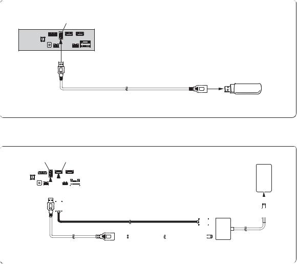
USB Connector
To USB flash drive, iPod/iPhone or Android smartphone.
HDMI Input Connector
HDMI Output Connector
Power Supply Connector
W.REMOTE Connector
PRE OUT Connector
DAB Antenna Connector
To DAB Antenna (sold separately).
Usable AV/RCA Interface Cable (4-pole mini AV plug to 3-RCA)
Wiring convention of this system is as follows;
Audio L (White)

 Audio R (Red)
 Ground
Video (Yellow)
(Yellow)
(Red) |
|
|
|
|
|
|
|
Video input terminal |
|
|
|
|
|
|
|
||
|
|
|
|
|
|
|
|
|
(White) |
|
|
|
|
|
|
|
Audio input terminal (R, L) |
|
|
|
|
|
|
|
•Configuration commercially available 4-pole mini AV plugs is not standardised.
7-EN

If an ACC power supply is not available
Connection Diagram of SPST Switch (sold separately)
|
|
|
ACC |
|
|||
X803D-U/ |
|
|
(Red) |
|
|
|
|
INE-W720D |
|
|
BATTERY |
|
|
||
|
|
|
|
|
|
|
(Yellow) |
|
SPST SW (Optional) |
FUSE (5A) |
|||||
(Optional) |
||||||
|
||||||
|
|
|
|
|
|
|
|
|
|
|
|
|
|
FUSE (20A) (Optional)
Battery
•If your vehicle has no ACC power supply, add an SPST (single-pole, single-throw) switch (sold separately) and fuse (sold separately).
•The diagram and the fuse amperage shown above are in the case when the unit is used individually.
•If the switched power (ignition) lead of the unit is connected directly to the positive (+) post of the vehicle’s battery, the unit draws some current (several hundred milliamperes) even when its switch is placed in the OFF position, and the battery may be discharged.
To prevent external noise from entering the audio system.
•Locate the unit and route the leads at least 10 cm away from the car harness.
•Keep the battery power leads as far away from other leads as possible.
•Connect the ground lead securely to a bare metal spot (remove any paint, dirt or grease if necessary) of the car chassis.
•If you add an optional noise suppressor, connect it as far away from the unit as possible. Your Alpine dealer carries various noise suppressors, contact them for further information.
•Your Alpine dealer knows best about noise prevention measures so consult your dealer for further information.
8-EN
System Example
Connection of an iPod/iPhone
When connecting to an iPod/iPhone with a Lightning connector
USB connector
USB extension cable (Included)
When connecting to iPhone 4S
USB connector
USB extension cable (Included)
iPod/iPhone with a Lightning connector (sold separately)
Lightning to USB Cable
KCU-471i (sold separately)
iPhone 4S
(sold separately)
Included with iPhone 4S
9-EN

Connection of a Flash Drive
USB connector
USB extension cable (Included)
USB Flash Drive (sold separately)
• Do not leave a flash drive in a vehicle for a long time. Heat and humidity may damage the flash drive.
Connection of an HDMI Device (iPhone with a Lightning connector)
USB connector |
|
HDMI input connector* |
iPhone with a Lightning |
|||||||||
|
connector (sold separately) |
|||||||||||
|
|
|
|
|
|
|
|
|
|
|
|
|
|
|
|
|
|
|
|
|
|
|
|
|
|
|
|
|
|
|
|
|
|
|
|
|
|
|
|
|
|
|
|
|
|
|
|
|
|
|
|
|
|
|
|
|
|
|
|
|
|
|
|
|
|
|
|
|
|
|
|
|
|
|
|
|
|
|
|
|
|
|
|
|
|
|
|
|
|
|
|
|
|
|
|
|
|
|
|
|
|
|
|
|
|
|
|
|
|
|
|
|
|
|
|
|
|
|
|
|
|
|
|
|
|
|
|
|
|
|
|
|
|
|
|
|
|
|
|
|
|
|
|
|
|
|
|
|
|
|
|
|
|
|
|
HDMI connection kit KCU-610HD (sold separately)
|
|
|
|
|
|
|
|
|
|
|
|
|
|
|
|
|
|
|
|
|
|
|
|
|
|
|
|
|
|
|
|
|
|
|
|
|
|
|
|
|
|
|
|
|
|
|
|
|
|
|
|
|
|
|
|
|
|
|
|
|
|
|
|
|
|
|
|
|
|
|
|
|
|
|
|
|
|
|
|
|
|
|
|
|
|
|
|
|
|
|
|
|
|
|
|
|
|
|
|
|
|
|
|
|
|
|
|
|
|
|
|
|
|
|
USB extension cable |
|
|
|
|
|
|
|
|
Lightning to USB Cable |
|
|
|
|
|
Lightning Digital AV Adapter |
|||||||
(Included) |
|
|
|
|
|
|
|
|
KCU-471i (sold separately) |
|
|
|
|
|
(Apple Inc., products) |
|||||||
|
|
|
|
|
|
|
|
|
|
|
|
|
|
|
|
|
|
(sold separately) |
||||
*When connecting an HDMI connection cable, be sure to secure it using the supplied HDMI Fixation Bracket. For details on how to secure it, see “Note on using HDMI Connection Cables” (page 4).
• Set the HDMI Setup to “HDMI.” For details, refer to “HDMI Setup” in the OWNER’S MANUAL (CD-ROM).
10-EN
Connection of an HDMI Device (Android device)
|
|
|
|
|
|
|
|
|
|
|
Android device with |
|
USB connector |
|
HDMI input connector* |
HDMI connector |
|
||||||||
|
(sold separately) |
|
||||||||||
|
|
|
|
|
|
|
|
|
|
|
|
|
|
|
|
|
|
|
|
|
|
|
|
|
|
|
|
|
|
|
|
|
|
|
|
|
|
|
|
|
|
|
|
|
|
|
|
|
|
|
|
|
|
|
|
|
|
|
|
|
|
|
|
|
|
|
|
|
|
|
|
|
|
|
|
|
|
|
|
|
|
|
|
|
|
|
|
|
|
|
|
|
|
|
|
|
|
|
|
|
|
|
|
|
|
|
|
|
|
|
|
|
|
|
|
|
|
|
|
|
|
|
|
|
|
|
|
|
|
|
|
|
|
|
|
|
|
|
|
|
|
|
USB extension cable |
HDMI connection kit KCU-610HD (sold separately) |
|
(Included) |
|
|
|
HDMI connection cable |
HDMI Type-D |
|
conversion adapter |
|
Micro USB conversion cable
Android device with MHL connector (sold separately)
MHL connection kit KCU-610MH (sold separately)
HDMI connection cable
MHL conversion adapter
Micro USB conversion cable
•A connection kit or adapter kit suitable for the type of terminal on the connecting device is required.
•Set the HDMI Setup to “HDMI.” For details, refer to “HDMI Setup” in the OWNER’S MANUAL (CD-ROM).
*When connecting an HDMI connection cable, be sure to secure it using the supplied HDMI Fixation Bracket. For details on how to secure it, see “Note on using HDMI Connection Cables” (page 4).
11-EN

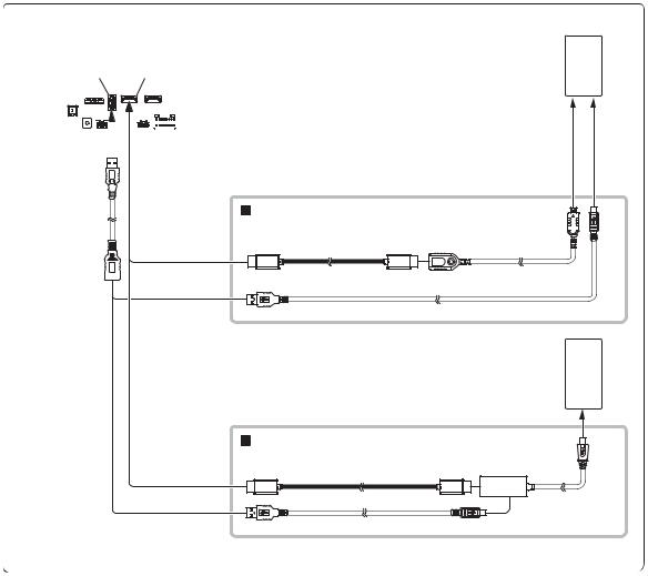
Connection of a DVE-5300 and a Rear Monitor with HDMI support
Rear Monitor with HDMI support
(sold separately)
|
HDMI input connector |
HDMI connection cable (included with DVE-5300) |
HDMI connection cable |
(sold separately) |
HDMI output connector |
HDMI input connector* |
HDMI output connector* |
|
DVE-5300 (sold separately) |
|
|
|
|
W.REMOTE connector |
|
|
|
|
W.REMOTE cable |
|
REMOTE IN |
DVD REMOTE |
MON REMOTE |
REMOTE IN |
(Brown) |
(Brown) |
(Brown) |
|
REMOTE OUT |
DVD STATUS IN |
REMOTE IN |
REMOTE OUT |
(Brown) |
(Red/White) |
(Brown/White) |
|
Remote Control Output Lead (Brown) (For DVD Plyer
DVE-5300)
Remote Control Output Lead (Brown) (For Rear Monitor)
Remote Control Input Lead (Brown/White) (For Rear
Monitor)
DVD Control Input Lead (Red/White) (For DVD Player
DVE-5300)
* When connecting an HDMI connection cable, be sure to secure it using the supplied HDMI Fixation Bracket. For details on how to secure it, see “Note on using HDMI Connection Cables” (page 4).
• Set the HDMI Setup to “DVD.” For details, refer to “HDMI Setup” in the OWNER’S MANUAL (CD-ROM).
12-EN

Connection of a Mobile Digital TV Receiver or USB Player
CAN I/F connector
|
W.REMOT connector |
|
|
|
W.REMOTE cable |
|
|
CAN I/F cable |
REMOTE OUT |
REMOTE IN |
|
(Brown) |
(White/Brown) |
||
|
|||
|
(Yellow) |
To Video Output terminal |
|
|
|
||
|
(Red) |
Mobile Digital TV Receiver |
|
|
(sold separately) |
||
|
AUX INPUT |
or |
|
|
USB Player (sold separately) |
||
|
|
||
|
(White) |
To Audio Output terminal |
|
|
|
AUX Input Connector |
AV/RCA Interface Cable (4-pole mini AV plug to 3-RCA) |
Remote Control Output Lead (Brown) |
(sold separately) |
|
|
|
RCA Extension Cable (sold separately) |
•For details on using an AV/RCA interface cable (4-pole mini AV plug to 3-RCA), see “Usable AV/RCA Interface Cable (4-pole mini AV plug to 3-RCA)” (page 7).
•Set the AUX Name to “DVB-T” or “USB Player.” For details, refer to “Setting the Auxiliary (AUX) Name” in the OWNER’S MANUAL (CD-ROM).
Connection of an External Device
CAN I/F connector
CAN I/F cable
|
(Yellow) |
To Video Output terminal |
|
|
|
|
(Red) |
External Device |
|
|
|
AUX INPUT |
|
(sold separately) |
(White) |
|
|
|
|
|
|
|
To Audio Output terminal |
AUX Input Connector |
AV/RCA Interface Cable (4-pole mini AV plug to 3-RCA) |
|
(sold separately) |
|
RCA Extension Cable (sold separately) |
•You can change the name of an external device. For details, refer to “Setting the Auxiliary (AUX) Name” in the OWNER’S MANUAL (CD-ROM).
•For details on using an AV/RCA interface cable (4-pole mini AV plug to 3-RCA), see “Usable AV/RCA Interface Cable (4-pole mini AV plug to 3-RCA)” (page 7).
13-EN

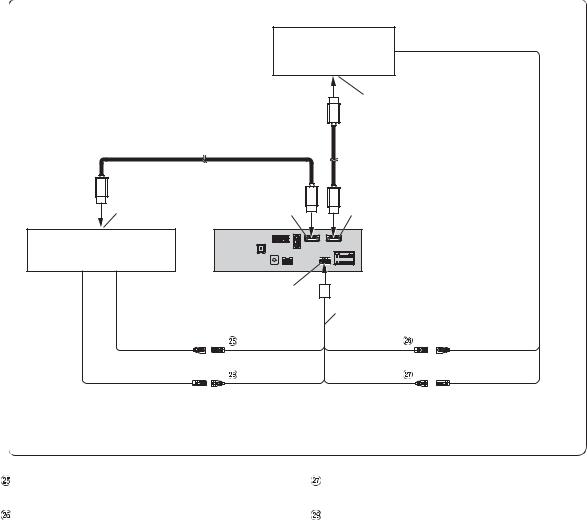
Connection of an External Amplifier
PRE OUT connector |
Power Supply connector |
|
REMOTE ON |
|
|
(Blue/White) |
|
|
REMO |
REMOTE ON |
|
|
|
||
|
(Blue/White) |
(Blue/White) |
|
|
Power cable |
|
|
|
(Red) |
|
|
PRE OUT cable |
SUBW |
Amplifier for subwoofer |
Subwoofer |
|
|
(sold separately) |
|
|
|
|
|
|
(White) |
To subwoofer input terminal |
|
|
(Red) |
To front input terminal |
|
|
|
|
|
|
FRONT OUT |
|
Front speaker |
|
|
|
|
|
(White) |
Amplifier 4 ch |
|
|
(Red) |
(sold separately) |
|
|
|
|
REAR OUT
|
Rear speaker |
(White) |
To rear input terminal |
|
Remote Turn-On Lead (Blue/White)  RCA Extension Cable (sold separately)
Subwoofer RCA Connectors
Front Output RCA Connectors
Rear Output RCA Connectors
14-EN
Connection of a Rearview camera
CAN I/F connector
|
|
|
|
|
|
|
|
|
|
|
|
|
|
|
Power Supply connector |
|
|
|
|
|
|
|||||||||||||
|
|
|
|
|
|
|
|
|
|
|
|
|
|
|
|
|
|
|
|
|
||||||||||||||
|
|
|
|
|
|
|
|
|
|
|
|
|
|
|
|
|
|
|
|
|
||||||||||||||
|
|
|
|
|
|
|
|
|
|
|
|
|
|
|
|
|
|
|
|
|
||||||||||||||
|
|
|
|
|
|
|
|
|
|
|
|
|
|
|
|
|
|
|
|
|
||||||||||||||
|
|
|
|
|
|
|
|
|
|
|
|
|
|
|
|
|
|
|
|
|
||||||||||||||
|
|
|
|
|
|
|
|
|
|
|
|
|
|
|
|
|
|
|
|
|
||||||||||||||
|
|
|
|
|
|
|
|
|
|
|
|
|
|
Power cable |
|
|
|
|
|
|
||||||||||||||
|
|
|
|
|
|
|
|
|
|
|
|
|
|
|
|
|
|
|
|
Reverse |
|
|
|
|
|
|
||||||||
|
|
|
|
|
|
|
|
|
|
|
|
|
|
|
|
|
|
|
|
|
|
|
|
Connect to the plus side of the car’s reverse lamp. |
|
|||||||||
CAN I/F cable |
|
|
|
|
|
|
|
|
|
|
|
|
|
|
|
|
|
|
|
(Orange/White) |
|
|
|
|
|
|
||||||||
|
|
|
|
|
|
|
|
|
|
|
|
|
|
|
|
|
|
|
|
|
|
|
|
|
|
|
|
|||||||
|
|
|
CAMERA |
|
|
|
|
|
Camera extension cable |
HCE-C127D/HCE-C157D/HCE-C252RD |
|
|||||||||||||||||||||||
|
|
|
|
|
|
|
|
|
|
|
|
|
|
|
|
|
|
|
|
|
|
|
||||||||||||
|
|
|
|
|
|
|
|
|
|
|
|
|
|
|
|
|
|
|
|
|
|
(included with direct rearview camera) |
(sold separately) |
|
||||||||||
Direct CAMERA Input Connector  Reverse Lead (Orange/White)
• Set the Camera Select to “Rear.” For details, refer to “Setting the Camera Input” in the OWNER’S MANUAL (CD-ROM).
Connection of a Frontview camera
CAN I/F connector
CAN I/F cable |
|
CAMERA |
HCE-C257FD/HCE-C212FD |
Camera extension cable |
|
(included with direct rearview camera) |
(sold separately) |
Direct CAMERA Input Connector
• Set the Camera Select to “Front.” For details, refer to “Setting the Camera Input” in the OWNER’S MANUAL (CD-ROM).
15-EN

DEUTSCH
Inhalt |
|
WARNUNG .................................................... |
2 |
VORSICHT ..................................................... |
2 |
Vorsichtsmaßnahmen ................................. |
3 |
Lieferumfang .......................................................... |
3 |
Einbau ..................................................................... |
3 |
Vorsichtshinweise zum Installationsort ......... |
3 |
Montieren der GPS-Antenne im Fahrzeug .... |
3 |
Einbau des Mikrofons ....................................... |
4 |
Installationsbeispiel mit der |
|
Originalmontagehalterung ........................... |
4 |
Anschlüsse .............................................................. |
5 |
Bei Fahrzeugen ohne ACC- |
|
Spannungsversorgung ................................... |
8 |
Systembeispiel ........................................................ |
9 |
1-DE

 WARNUNG
Dieses Symbol weist auf wichtige Anweisungen hin. Bei Nichtbeachtung besteht die Gefahr von schweren Verletzungen oder Todesfällen.
GERÄT NICHT ÖFFNEN.
Andernfalls besteht Unfallgefahr, Feuergefahr oder die Gefahr eines elektrischen Schlages.
KLEINE GEGENSTÄNDE WIE SCHRAUBEN VON KINDERN FERNHALTEN.
Werden solche Gegenstände verschluckt, besteht die Gefahr schwerwiegender Verletzungen. Suchen Sie unverzüglich einen Arzt auf, wenn ein Kind einen solchen Gegenstand verschluckt.
SICHERUNGEN IMMER DURCH SOLCHE MIT DER RICHTIGEN AMPEREZAHL ERSETZEN.
Andernfalls besteht Feuergefahr oder die Gefahr eines elektrischen Schlages.
LÜFTUNGSÖFFNUNGEN UND KÜHLKÖRPER NICHT ABDECKEN.
Andernfalls kann es zu einem Wärmestau im Gerät kommen, und es besteht Feuergefahr.
DAS GERÄT NUR AN EIN 12-V-BORDNETZ IN EINEM FAHRZEUG ANSCHLIESSEN.
Andernfalls besteht Feuergefahr, die Gefahr eines elektrischen Schlages oder anderer Verletzungen.
AUF KORREKTE ANSCHLÜSSE ACHTEN.
Bei fehlerhaften Anschlüssen besteht Feuergefahr, und es kann zu Schäden am Gerät kommen.
NUR IN FAHRZEUGEN MIT 12-VOLT-BORDNETZ UND MINUS AN MASSE VERWENDEN.
Fragen Sie im Zweifelsfall Ihren Händler. Andernfalls besteht Feuergefahr usw.
VOR DEM ANSCHLUSS DAS KABEL VOM MINUSPOL DER BATTERIE ABKLEMMEN.
Andernfalls besteht die Gefahr eines elektrischen Schlages oder Verletzungsgefahr durch einen Kurzschluss.
DAFÜR SORGEN, DASS SICH DIE KABEL NICHT IN GEGENSTÄNDEN IN DER NÄHE VERFANGEN.
Verlegen Sie die Kabel wie im Handbuch beschrieben, damit sie beim Fahren nicht hinderlich sind. Kabel, die sich im Lenkrad, im Schalthebel, im Bremspedal usw. verfangen, können zu äußerst gefährlichen Situationen führen.
ELEKTRISCHE KABEL NICHT SPLEISSEN.
Kabel dürfen nicht abisoliert werden, um andere Geräte mit Strom zu versorgen. Andernfalls wird die Strombelastbarkeit des Kabels überschritten, und es besteht Feuergefahr oder die Gefahr eines elektrischen Schlages.
BEIM BOHREN VON LÖCHERN LEITUNGEN UND KABEL NICHT BESCHÄDIGEN.
Wenn Sie beim Einbauen Löcher in das Fahrzeugchassis bohren, achten Sie unbedingt darauf, die Kraftstoffleitungen und andere Leitungen, den Benzintank und elektrische Kabel nicht zu berühren, zu beschädigen oder zu blockieren. Andernfalls besteht Feuergefahr.
BOLZEN UND MUTTERN DER BREMSANLAGE NICHT ALS MASSEPUNKTE VERWENDEN.
Verwenden Sie für Einbau oder Masseanschluß NIEMALS Bolzen oder Muttern der Bremsbzw. Lenkanlage oder eines anderen sicherheitsrelevanten Systems oder des Benzintanks. Andernfalls besteht die Gefahr, dass Sie die Kontrolle über das Fahrzeug verlieren oder ein Feuer ausbricht.
DAS GERÄT NICHT AN EINER STELLE EINBAUEN, AN DER ES BEIM FAHREN HINDERLICH SEIN KÖNNTE, WEIL ES Z. B. DAS LENKRAD ODER DEN SCHALTHEBEL BLOCKIERT.
Andernfalls ist möglicherweise keine freie Sicht nach vorne gegeben, oder die Bewegungen des Fahrers sind so eingeschränkt, dass Unfallgefahr besteht.
DIE DISPLAYEINHEIT NICHT IN DER NÄHE DES BEIFAHRER-AIRBAGS EINBAUEN.
Bei unsachgemäßem Einbau kann der Airbag versagen oder beim Aufblähen die Displayeinheit in die Fahrgastzelle schleudern und Verletzungen verursachen.
 VORSICHT
Dieses Symbol weist auf wichtige Anweisungen hin. Bei Nichtbeachtung besteht die Gefahr von Verletzungen bzw. Sachschäden.
VERKABELUNG UND EINBAU VON FACHPERSONAL AUSFÜHREN LASSEN.
Die Verkabelung und der Einbau dieses Geräts erfordern technisches Geschick und Erfahrung. Zu Ihrer eigenen Sicherheit sollten Sie Verkabelung und Einbau dem Händler überlassen, bei dem Sie das Gerät erworben haben.
NUR DAS VORGESCHRIEBENE ZUBEHÖR VERWENDEN UND DIESES SICHER EINBAUEN.
Verwenden Sie ausschließlich das vorgeschriebene Zubehör. Andernfalls wird das Gerät möglicherweise beschädigt, oder es lässt sich nicht sicher einbauen. Wenn sich Teile lösen, stellen diese eine Gefahrenquelle dar, und es kann zu Betriebsstörungen kommen.
DIE KABEL SO VERLEGEN, DASS SIE NICHT GEKNICKT ODER DURCH SCHARFE KANTEN GEQUETSCHT WERDEN.
Verlegen Sie die Kabel so, dass sie sich nicht in beweglichen Teilen wie den Sitzschienen verfangen oder an scharfen Kanten oder spitzen Ecken beschädigt werden können. So verhindern Sie eine Beschädigung der Kabel. Wenn Sie ein Kabel durch eine Bohrung in einer Metallplatte führen, schützen Sie die Kabelisolierung mit einer Gummitülle vor Beschädigung durch die Metallkanten der Bohrung.
DAS GERÄT NICHT AN STELLEN EINBAUEN, AN DENEN ES HOHER FEUCHTIGKEIT ODER STAUB AUSGESETZT IST.
Bauen Sie das Gerät so ein, dass es vor hoher Feuchtigkeit und Staub geschützt ist. Wenn Feuchtigkeit oder Staub in das Gerät gelangen, kann es zu Betriebsstörungen kommen.
2-DE
Vorsichtsmaßnahmen
•Trennen Sie unbedingt das Kabel vom (–) Batteriepol, bevor Sie das Gerät installieren. Dadurch vermeiden Sie die Gefahr einer Beschädigung des Geräts, falls es zu einem Kurzschluss kommt.
•Auf korrekten Anschluss der farbcodierten Kabel achten! Anschlussfehler können Betriebsstörungen des Geräts bzw. Fahrzeugs zur Folge haben.
•Beim Anschließen an das Bordnetz des Fahrzeugs unbedingt die werkseitig eingebauten Komponenten (z. B. Bordrechner) beachten. Keinesfalls die Stromversorgung für das Gerät an diesen Komponenten abgreifen. Beim Anschluss des Geräts im Sicherungskasten darauf achten, dass die Sicherung des gewählten Stromkreises die für das Gerät vorgeschriebene Amperezahl aufweist. Wenden Sie sich im Zweifelsfall an Ihren Alpine-Händler.
•Das Gerät wird über RCA-Buchsen an andere Komponenten (z. B. Verstärker) angeschlossen. Zum Anschließen eines anderen Geräts werden unter Umständen Steckeradapter benötigt. Lassen Sie sich diesbezüglich von Ihrem autorisierten Alpine-Händler beraten.
•Achten Sie darauf, die Lautsprecherkabel (–) an den Lautsprecheranschluss (–) anzuschließen. Verbinden Sie auf keinen Fall Lautsprecherkabel für den linken und den rechten Kanal miteinander oder mit der Fahrzeugkarosserie.
Lieferumfang |
|
|
• |
X803D-U oder INE-W720D........................................................................ |
1 |
• |
Stromversorgungskabel ............................................................................ |
1 |
• |
GPS-Antenne ................................................................................................. |
1 |
• |
Antennenmontageplatte.......................................................................... |
1 |
• |
Kabelklemme für Antenne .............................................................. |
1 Satz |
• |
USB-Anschlusskabel.................................................................................... |
1 |
• |
PRE OUT-Kabel .............................................................................................. |
1 |
• |
Mikrofon .......................................................................................................... |
1 |
• |
CAN I/F-Kabel ................................................................................................ |
1 |
• |
W.REMOTE-Kabel.......................................................................................... |
1 |
• |
Frontplatte (nur INE-W720D) ................................................................... |
1 |
• |
HDMI-Halterung ........................................................................................... |
1 |
• |
Senkschraube (M5×8)................................................................................. |
4 |
• |
Schraube (M5×8).......................................................................................... |
4 |
• |
Bedienungsanleitung........................................................................ |
1 Satz |
Einbau
Benutzer von X803D-U
Um das X803D-U einzubauen, schlagen Sie in der Anleitung des separat erworbenen Einbausatzes für den jeweiligen Fahrzeugtyp nach.
Vorsicht
Achten Sie auf ungehinderte Luftzirkulation im Bereich des Ventilators. Falls die Belüftungsöffnungen verdeckt oder verschlossen werden, kommt es zu Hitzestau im Gerät und Brandgefahr.
<Beispiel> |
Belüftungsöffnung |
Rückseite des Geräts |
Vorsichtshinweise zum Installationsort
Installationswinkel
Die Installation sollte in einem Winkel zwischen horizontal und 30° erfolgen. Liegt der Installationswinkel außerhalb dieses Bereichs, kann es zu Leistungseinbußen und möglicherweise zu Schäden kommen.
0 - 30°
Montieren der GPS-Antenne im Fahrzeug
1Reinigen Sie die Montagestelle.
2Bringen Sie die Montageplatte für die GPS-Antenne an.
3Montieren Sie die GPS-Antenne.
GPS-Antenne
Montageplatte für GPS-Antenne
Dieses Gerät
•Montieren Sie die GPS-Antenne nicht in der Mittelkonsole.
-Montieren Sie die GPS-Antenne auf einer ebenen Fläche auf dem Armaturenbrett oder der Hutablage.
-Achten Sie darauf, die GPS-Antenne nicht durch Metallgegenstände abzudecken.
•Wenn die GPS-Antenne nahe am Gerät montiert wird, verringert sich die Empfangsqualität und die Position des Fahrzeugs wird unter Umständen nicht korrekt angezeigt.
-Montieren Sie die GPS-Antenne in ausreichender Entfernung von diesem Gerät.
-Halten Sie das Kabel der GPS-Antenne von der Rückseite des Geräts fern.
•Bestimmte Arten von wärmeabweisendem bzw. wärmeabsorbierendem Glas können Hochfrequenzwellen blockieren. Wenn der Empfang schlecht ist und die Antenne im Fahrzeug installiert ist, montieren Sie sie versuchsweise außen am Fahrzeug.
3-DE

Einbau des Mikrofons
Beachten Sie Folgendes für den sicheren Gebrauch:
•Die Position muss stabil und sicher sein.
•Das Sichtfeld und der Aktionsradius des Fahrers dürfen nicht versperrt werden.
•Das Mikrofon ist dort angebracht, wo die Stimme des Fahrers gut hörbar ist (zum Beispiel an der Sonnenblende).
Beim Sprechen in das Mikrofon sollten Sie nicht die Haltung ändern müssen, die Sie zum Fahren eingenommen haben. Dies könnte Ihre Aufmerksamkeit vom sicheren Fahren Ihres Wagens ablenken.
Beachten Sie die Richtung und den Abstand beim Anbringen des Mikrofons. Überprüfen Sie, ob die Stimme des Fahrers am ausgewählten Ort gut hörbar ist.
Mikrofon
Kabelklemme (separat erhältlich)
Hinweis zum Verwenden von HDMI-Verbindungskabeln
Wenn Sie HDMI-Verbindungskabel verwenden, sichern Sie die Kabel mit der mitgelieferten HDMI-Halterung an den HDMI-Anschlüssen.
1Schieben Sie die HDMI-Halterung in die Kerben (A) ein.
2Sichern Sie sie mit der Schraube (B).
HDMI-Anschluss
(A) |
(A) |
HDMI-Halterung
(Mitgeliefert)
(B)
Installationsbeispiel mit der
Originalmontagehalterung
1Bringen Sie die Originalmontagehalterung mit den mitgelieferten Schrauben am Gerät an.
Massekabel*
Chassis
Originalmontagehalterung
Schrauben (M5×8) (Mitgeliefert)
Frontplatte (Mitgeliefert)
*Verbinden Sie das Massekabel fest mit einer bereits an einem Metallteil des Fahrzeugs vorhandenen Schraube (mit ( ) markiert) oder mit einer sauberen, blanken Metallstelle der Fahrzeugkarosserie.
2Schließen Sie alle anderen Kabel des Geräts gemäß den Angaben unter „Anschlüsse“ (Seite 5) an.
3Montieren Sie das Gerät in einem Fahrzeug.
•Fixieren Sie die Kabel sorgfältig. Achten Sie darauf, dass sie nicht in bewegliche Teile wie Sitzschienen geraten können, und verlegen Sie sie nicht in der Nähe von scharfen Kanten oder spitzen Ecken. Andernfalls könnten sie beschädigt werden.
4-DE
Anschlüsse
SPEED SENSOR (Grün/Weiß) CAMERA
CONNECT2 I/F
AUX INPUT
CAN I/F-Kabel
REMO (Blau/Weiß)
REVERSE
(Orange/Weiß) PARKING BRAKE
(Gelb/Blau)
ACC
(Rot)
GND (Schwarz)
P. ANT
(Blau) BATT
(Gelb) Stromversorgungs kabel
(Grün)
(Grün/Schwarz)  (Weiß)
(Weiß/Schwarz)
(Grau/Schwarz) 
(Grau)
(Violett/
Schwarz)
PRE OUT-Kabel |
W.REMOTE-Kabel |
(Violett) |
DVD REMOTE
(Braun)
MON REMOTE
(Braun) REMOTE IN
(Braun/Weiß) REMOTE OUT
(Braun)
DVD STATUS IN
(Rot/Weiß) STEERING REMOTE
MIC IN
SUBW
FRONT OUT
REAR OUT
Antenne
ISO-Antennenstecker GPS-Antenne (Mitgeliefert)
An die Fahrzeug-
Drehzahlpausenleitung
An die Frontoder Heckkamera
An CAN-Schnittstellenbox
Zu AUX-Ausgabegerät
An den Verstärker bzw. Equalizer
An die Plusader des Rückfahrscheinwerferkabels am Fahrzeug
An das Handbremsen-Signalkabel
An Motorantenne oder Rückfahrkamera Ausgangsspannung
Zündschloss
Batterie
Linker Hecklautsprecher
Linker Frontlautsprecher
Lautsprecher
Rechter Frontlautsprecher
Rechter Hecklautsprecher
An das Fernbedienungs-
Eingangskabel des DVE-5300
An das FernbedienungsEingangskabel des Fondmonitors
An das
Fernbedienungs-Ausgangskabel
An das
Fernbedienungs-Eingangskabel
An das Fernbedienungs-
Ausgangskabel des DVE-5300
An Lenkradfernbedienungs-
Schnittstellenbox
Mikrofon (Mitgeliefert)
An Verstärkereingang, wenn ein externer Verstärker hinzugefügt wird
5-DE

Radioantennen-Anschluss
ISO/JASO-Antennenadapter (separat erhältlich)
Ein ISO/JASO-Antennenadapter ist je nach Fahrzeug erforderlich.
Drehzahlsensorkabel (Grün/Weiß)
Eine falsche Verbindung der Drehzahlimpulsleitung kann zu einem Versagen wichtiger Sicherheitsfunktionen (z. B. Bremsen oder Airbags) des Fahrzeugs führen. Dies kann tödliche Unfälle nach sich ziehen. Wir empfehlen dringend, die Installation von einem ausgebildeten und autorisierten Alpine-Händler durchführen zu lassen.
Direkter CAMERA-Eingangsanschluss
Verwendbar, wenn die optionale Direktkamera angeschlossen ist.
CAN-Schnittstellenanschluss
An CAN-Schnittstellenbox
AUX-Eingangsanschluss
Zuleitung für AUX Video-/Audiosignal.
•Es ist ein separat erhältliches AV/RCA-Schnittstellenkabel (4- poliger Mini-AV-Stecker zu 3-RCA) erforderlich. Einzelheiten zum Verwenden eines AV/RCA-Schnittstellenkabels (4-poliger Mini-AV-Stecker an 3-RCA) finden Sie unter „Geeignetes AV/ RCA-Schnittstellenkabel (4-poliger Mini-AV-Stecker an 3-RCA)“ (Seite 7).
Ferneinschaltkabel (Blau/Weiß)
Verbinden Sie dieses Kabel mit dem Ferneinschaltkabel des Verstärkers oder Soundprozessors.
Rückfahrkabel (Orange/Weiß)
Schließen Sie das Kabel an den Pluspol der Rückfahrscheinwerfer des Fahrzeugs an. Diese Scheinwerfer leuchten auf, wenn der Rückwärtsgang (R) eingelegt wird. Sofern dieses Kabel richtig angeschlossen ist, wird anstelle des Videobildes automatisch das Bild von der Rückfahrkamera angezeigt, sobald der Rückwärtsgang (R) eingelegt wird.
Handbrems-Signalkabel (Gelb/Blau)
Verbinden Sie dieses Kabel mit der Stromversorgung des Handbremsschalters, damit dem Gerät Statussignale der Handbremse gemeldet werden.
ISO-Stromversorgungsanschluss
Kabel für geschaltete Spannungsversorgung (Zündung) (Rot)
Schließen Sie dieses Kabel an eine freie Klemme im Sicherungskasten oder eine andere nicht belegte Versorgungsleitung an, die bei eingeschalteter Zündung bzw. in Position ACC (+) 12 V liefert.
Massekabel (Schwarz)
Dieses Kabel an einem geeigneten Punkt an Fahrzeugmasse legen.
Achten Sie darauf, dass der gewählte Punkt lackund fettfrei ist und schrauben Sie das Kabel mit der mitgelieferten Blechschraube gut fest.
Motorantennenkabel (Blau)
Verbinden Sie dieses Kabel mit dem +B-Anschluss der Motorantenne, falls vorhanden.
•Wenn die Rückfahrkamera Ihres Fahrzeugs mit einer Elektrikschutzabdeckung ausgestattet ist, ändern Sie die Einstellung von Rückfahrkamera Ausgangsspannung auf On und verbinden Sie diese Leitung mit dem Anschluss +B der Rückfahrkamera.
•Diese Leitung sollte nur zum Steuern der Motorantenne oder der Rückfahrkamera des Fahrzeugs verwendet werden. Verwenden Sie dieses Kabel nicht zum Einschalten eines Verstärkers oder Soundprozessors usw.
Batteriezuleitungskabel (Gelb)
Verbinden Sie dieses Kabel mit dem Pluspol (+) der Fahrzeugbatterie.
Sicherungshalter (15 A)
ISO-Stecker (Lautsprecherausgänge)
Kabel für linken Hecklautsprecher (+) (Grün)
Kabel für linken Hecklautsprecher (–) (Grün/Schwarz) Kabel für linken Frontlautsprecher (+) (Weiß)
Kabel für linken Frontlautsprecher (–) (Weiß/Schwarz) Kabel für rechten Frontlautsprecher (–) (Grau/Schwarz) Kabel für rechten Frontlautsprecher (+) (Grau)
Kabel für rechten Hecklautsprecher (–) (Violett/Schwarz) Kabel für rechten Hecklautsprecher (+) (Violett)
Fernbedienungs-Ausgangskabel (Braun) (Für DVDPlayer DVE-5300)
Wird mit dem Fernbedienungs-Eingangskabel verbunden. Über dieses Kabel werden die Steuersignale der Fernbedienung ausgegeben.
Fernbedienungs-Ausgangskabel (Braun) (Für Fondmonitor)
Wird mit dem Fernbedienungs-Eingangskabel verbunden. Über dieses Kabel werden die Steuersignale der Fernbedienung ausgegeben.
Fernbedienungs-Eingangskabel (Braun/Weiß)
Wird mit dem Fernbedienungs-Ausgangskabel des externen Alpine-Gerätes verbunden.
6-DE

Fernbedienungs-Ausgangskabel (Braun)
Wird mit dem Fernbedienungs-Eingangskabel verbunden. Über dieses Kabel werden die Steuersignale der Fernbedienung ausgegeben.
DVD-Steuerkabel (Rot/Weiß) (Für DVD-Player DVE-5300)
Wird mit dem Fernbedienungs-Ausgangskabel des DVD-Players DVE-5300 verbunden.
Lenkradfernbedienungs-Schnittstellenanschluss
An Lenkradfernbedienungs-Schnittstellenbox.
Einzelheiten zu den Anschlüssen können Sie bei Ihrem AlpineKundendienst in Erfahrung bringen.
MIC-Eingangsbuchse
An Mikrofon (Mitgeliefert)
•Stellen Sie bei Verwendung des inbegriffenen Mikrofons die Mikrofonauswahl auf „Add-on“. Einzelheiten dazu finden Sie unter „Auswählen des Mikrofons“ in der BEDIENUNGSANLEITUNG (CD-ROM).
RCA-Buchsen für Subwoofer
Die ROTE Buchse ist für den rechten Kanal, die WEISSE für den linken bestimmt.
RCA-Ausgangsbuchsen für Frontlautsprecher
Können zum Anschließen von Frontlautsprechern über die RCABuchsen verwendet werden. Die ROTE Buchse ist für den rechten Kanal, die WEISSE für den linken bestimmt.
RCA-Ausgangsbuchsen für Hecklautsprecher
Können zum Anschließen von Hecklautsprechern über die RCABuchsen verwendet werden. Die ROTE Buchse ist für den rechten Kanal, die WEISSE für den linken bestimmt.
GPS-Antennenbuchse
Schließen Sie die GPS-Antenne an (Mitgeliefert).
CAN I/F-Anschluss
USB-Anschluss
An USB-Flash-Laufwerk, iPod/iPhone oder Android-Smartphone.
HDMI-Eingang
HDMI-Ausgang
Stromversorgungsanschluss
W.REMOTE-Anschluss
PRE OUT-Anschluss
DAB-Antennenanschluss
An DAB-Antenne (separat erhältlich).
Geeignetes AV/RCA-Schnittstellenkabel (4-poliger Mini-AV-
Stecker an 3-RCA)
Verdrahtungskonvention dieses Systems:
Audio-L (Weiß)

 Audio-R (Rot)
 Erde
Erde
Video (Gelb)
(Gelb)
|
Videoeingang |
(Rot) |
|
(Weiß) |
Audioeingang (R, L) |
•Die Konfiguration handelsüblicher 4-poliger Mini-AV-Stecker ist nicht standardisiert.
7-DE

Bei Fahrzeugen ohne ACC-Spannungsversorgung
Anschlussschema für SPST-Schalter (separat erhältlich)
|
|
|
ACC |
|
|||
X803D-U/ |
|
|
(Rot) |
|
|
|
|
INE-W720D |
|
|
BATTERY |
|
|
||
|
|
|
|
|
|
|
(Gelb) |
|
SPST-Schalter (Option) |
SICHERUNG |
|||||
(5A) (Option) |
||||||
|
||||||
|
|
|
|
|
|
|
|
|
|
|
|
|
|
SICHERUNG (20A) (Option)
Batterie
•Wenn Ihr Fahrzeug keine ACC-Spannungsversorgung bietet, schließen Sie das Gerät über einen separat erhältlichen SPST-Schalter (Single-Pole, SingleThrow) und über eine separat erhältliche Sicherung an.
•Das Diagramm und der oben angegebene Ampere-Wert der Sicherung beziehen sich auf den Fall, dass das Gerät allein verwendet wird.
•Wenn die Zuleitung für die geschaltete Stromversorgung (über die Zündung) des Geräts direkt mit dem Pluspol (+) der Batterie des Fahrzeugs verbunden wird, zieht das Gerät eine gewisse Strommenge (mehrere hundert Milliampere), auch wenn sich der Schalter in der Position OFF befindet. Dies kann eine allmähliche Entladung der Fahrzeugbatterie zur Folge haben.
Zur Verhütung von Störeinstreuungen.
•Achten Sie beim Einbau darauf, dass das Gerät und die Anschlussund Verbindungskabel mindestens 10 cm vom nächsten Kabelbaum des Fahrzeugs entfernt sind.
•Verlegen Sie das Batterie-Zuleitungskabel so weit wie möglich entfernt von anderen Kabeln.
•Legen Sie das Massekabel gut an einem blanken Punkt des Fahrzeugchassis an Masse (ggf. Lack, Schmutz oder Fett an der betreffenden Stelle entfernen).
•Wenn Sie einen optionalen Entstörfilter verwenden, schalten Sie diesen so weit wie möglich vom Gerät entfernt in das Bordnetz. Ihr Alpine-Fachhändler hält eine Reihe wirkungsvoller Entstörfilter bereit und berät Sie gerne.
•Sollten Sie bezüglich der Entstörung Ihres Fahrzeugs weitere Fragen haben, wenden Sie sich bitte an Ihren Alpine-Fachhändler.
8-DE
Systembeispiel
Anschließen eines iPod/iPhone
Beim Anschließen an einen iPod/ein iPhone mit Lightning-Anschluss
|
USB-Anschluss |
|
|
|
|
|
|
|
|
|
|
|
iPod/iPhone mit Lightning- |
|
||||||||||
|
|
|
|
|
|
|
|
|
|
|
|
Anschluss (separat erhältlich) |
|
|||||||||||
|
|
|
|
|
|
|
|
|
|
|
|
|
|
|
|
|
|
|
|
|
|
|||
|
|
|
|
|
|
|
|
|
|
|
|
|
|
|
|
|
|
|
|
|
|
|
|
|
|
|
|
|
|
|
|
|
|
|
|
|
|
|
|
|
|
|
|
|
|
|
|
|
|
|
|
|
|
|
|
|
|
|
|
|
|
|
|
|
|
|
|
|
|
|
|
|
|
|
|
|
|
|
|
|
|
|
|
|
|
|
|
|
|
|
|
|
|
|
|
|
|
|
|
|
|
|
|
|
|
|
|
|
|
|
|
|
|
|
|
|
|
|
|
|
|
|
|
|
|
|
|
|
|
|
|
|
|
|
|
|
|
|
|
|
|
|
|
|
|
|
|
|
|
|
|
|
|
|
|
|
|
|
|
|
|
|
|
|
|
|
|
|
|
|
|
|
|
|
|
|
|
|
|
|
|
|
|
|
|
|
|
|
|
|
|
|
|
|
|
|
|
|
|
|
|
|
|
|
|
|
|
|
|
|
|
|
|
|
|
|
|
|
|
|
|
|
|
|
|
|
|
|
|
|
|
|
|
|
|
|
|
|
|
|
|
|
|
|
|
|
|
|
|
|
|
|
|
|
|
|
|
|
|
|
|
|
|
|
|
|
|
|
|
|
|
|
|
|
|
|
|
|
|
|
|
|
|
|
|
|
|
|
|
|
|
|
|
|
|
|
|
|
|
|
|
|
|
|
|
|
|
|
|
|
|
|
|
|
|
|
|
|
|
|
|
|
|
|
|
|
|
|
|
|
|
|
|
|
|
|
|
|
|
|
|
|
|
|
|
|
|
|
|
|
|
|
|
|
|
|
|
|
|
|
|
|
|
|
|
|
|
|
|
|
|
|
|
|
|
|
|
|
|
|
|
|
|
|
|
|
|
|
|
|
|
|
|
|
|
|
|
|
|
USB-Verlängerungskabel (Mitgeliefert) |
Lightning-zu-USB-Kabel |
|
KCU-471i (separat erhältlich) |
Bei Anschluss an ein iPhone 4S
USB-Anschluss
USB-Verlängerungskabel (Mitgeliefert)
iPhone 4S (separat erhältlich)
Im Lieferumfang des iPhone 4S enthalte
9-DE
Anschluss eines Flash-Laufwerks
USB-Anschluss
USB-Verlängerungskabel (Mitgeliefert)
USB-Flash-Laufwerk (separat erhältlich)
• Lassen Sie ein Flash-Laufwerk nicht für längere Zeit im Fahrzeug. Hitze und Feuchtigkeit können das Flash-Laufwerk beschädigen.
Anschluss eines HDMI-Geräts (iPhone mit Lightning-Anschluss)
|
|
|
|
|
|
|
|
|
|
|
iPhone mit Lightning- |
|
USB-Anschluss |
|
HDMI-Eingang* |
Anschluss (separat erhältlich) |
|||||||||
|
|
|
|
|
|
|
|
|
|
|
|
|
|
|
|
|
|
|
|
|
|
|
|
|
|
|
|
|
|
|
|
|
|
|
|
|
|
|
|
|
|
|
|
|
|
|
|
|
|
|
|
|
|
|
|
|
|
|
|
|
|
|
|
|
|
|
|
|
|
|
|
|
|
|
|
|
|
|
|
|
|
|
|
|
|
|
|
|
|
|
|
|
|
|
|
|
|
|
|
|
|
|
|
|
|
|
|
|
|
|
|
|
|
|
|
|
|
|
|
|
|
|
|
|
|
|
|
|
|
|
|
|
|
|
|
|
|
|
|
|
|
|
|
|
|
|
|
|
|
|
|
|
|
|
|
HDMI-Verbindungssatz KCU-610HD (separat erhältlich)
|
|
|
|
|
|
|
|
|
|
|
|
|
|
|
|
|
|
|
|
|
|
|
|
|
|
|
|
|
|
|
|
|
|
|
|
|
|
|
|
|
|
|
|
|
|
|
|
|
|
|
|
|
|
|
|
|
|
|
|
|
|
|
|
|
|
|
|
|
|
|
|
|
|
|
|
|
|
|
|
|
|
|
|
|
|
|
|
|
|
|
|
|
|
|
|
|
|
|
|
|
|
|
|
|
|
|
|
|
|
|
|
|
|
|
USB-Verlängerungskabel |
|
|
|
|
|
|
|
|
Lightning-zu-USB-Kabel |
|
|
|
|
|
Lightning-AV-Digitaladapter |
|||||||
(Mitgeliefert) |
|
|
|
|
|
|
|
|
KCU-471i (separat erhältlich) |
|
|
|
|
|
(Produkte von Apple Inc.) |
|||||||
|
|
|
|
|
|
|
|
|
|
|
|
|
|
|
|
|
|
(separat erhältlich) |
||||
*Wenn Sie ein HDMI-Verbindungskabel anschließen, sichern Sie es unbedingt mit der mitgelieferten HDMI-Halterung. Einzelheiten dazu finden Sie unter „Hinweis zum Verwenden von HDMI-Verbindungskabeln“ (Seite 4).
• Setzen Sie HDMI-Setup auf „HDMI“. Einzelheiten dazu finden Sie unter „HDMI-Einstellungen“ in der BEDIENUNGSANLEITUNG (CD-ROM).
10-DE

Anschluss eines HDMI-Geräts (Android-Geräts)
|
|
|
|
|
|
|
|
|
|
|
Android-Gerät mit |
|
USB-Anschluss |
|
HDMI-Eingang* |
HDMI-Anschluss |
|
||||||||
|
(separat erhältlich) |
|
||||||||||
|
|
|
|
|
|
|
|
|
|
|
|
|
|
|
|
|
|
|
|
|
|
|
|
|
|
|
|
|
|
|
|
|
|
|
|
|
|
|
|
|
|
|
|
|
|
|
|
|
|
|
|
|
|
|
|
|
|
|
|
|
|
|
|
|
|
|
|
|
|
|
|
|
|
|
|
|
|
|
|
|
|
|
|
|
|
|
|
|
|
|
|
|
|
|
|
|
|
|
|
|
|
|
|
|
|
|
|
|
|
|
|
|
|
|
|
|
|
|
|
|
|
|
|
|
|
|
|
|
|
|
|
|
|
|
|
|
|
|
|
|
|
|
|
|
|
|
|
|
|
|
|
|
|
|
|
USBVerlängerungskabel  (Mitgeliefert)
HDMI-Verbindungssatz KCU-610HD (separat erhältlich)
HDMI- |
HDMI-Typ-D- |
Verbindungskabel |
Adapter |
Micro-USB-Adapterkabel
Android-Gerät mit MHL-Anschluss (separat erhältlich)
MHL-Verbindungssatz KCU-610MH (separat erhältlich)
HDMI-Verbindungskabel
MHL-Adapter
Micro-USB-Adapterkabel
•Ein geeigneter Verbindungsoder Adaptersatz für die Art des Anschlusses am anzuschließenden Gerät ist erforderlich.
•Setzen Sie HDMI-Setup auf „HDMI“. Einzelheiten dazu finden Sie unter „HDMI-Einstellungen“ in der BEDIENUNGSANLEITUNG (CD-ROM).
*Wenn Sie ein HDMI-Verbindungskabel anschließen, sichern Sie es unbedingt mit der mitgelieferten HDMI-Halterung. Einzelheiten dazu finden Sie unter „Hinweis zum Verwenden von HDMI-Verbindungskabeln“ (Seite 4).
11-DE
Anschluss eines DVE-5300 und eines Fondmonitors mit HDMI-Unterstützung
Fondmonitor mit HDMI- |
|
Unterstützung |
|
(separat erhältlich) |
|
|
HDMI-Eingang |
HDMI-Verbindungskabel (mit DVE-5300 mitgeliefert) |
HDMI-Verbindungskabel |
(separat erhältlich) |
|
HDMI-Ausgang |
HDMI-Eingang* |
HDMI-Ausgang* |
|
DVE-5300 (separat erhältlich) |
|
|
|
|
W.REMOTE-Anschluss |
|
|
|
|
W.REMOTE-Kabel |
|
REMOTE IN |
DVD REMOTE |
MON REMOTE |
REMOTE IN |
(Braun) |
(Braun) |
(Braun) |
|
REMOTE OUT |
DVD STATUS IN |
REMOTE IN |
REMOTE OUT |
(Braun) |
(Rot/Weiß) |
(Braun/Weiß) |
|
Fernbedienungs-Ausgangskabel (Braun) (Für DVD- |
Fernbedienungs-Eingangskabel (Braun/Weiß) (Für |
Player DVE-5300) |
Fondmonitor) |
Fernbedienungs-Ausgangskabel (Braun) (Für |
DVD-Steuerkabel (Rot/Weiß) (Für DVD-Player DVE-5300) |
Fondmonitor) |
|
* Wenn Sie ein HDMI-Verbindungskabel anschließen, sichern Sie es unbedingt mit der mitgelieferten HDMI-Halterung. Einzelheiten dazu finden Sie unter „Hinweis zum Verwenden von HDMI-Verbindungskabeln“ (Seite 4).
• Setzen Sie HDMI-Setup auf „DVD“. Einzelheiten dazu finden Sie unter „HDMI-Einstellungen“ in der BEDIENUNGSANLEITUNG (CD-ROM).
12-DE
 Loading...