

Page 1
R
ALPINE ELECTRONICS MARKETING, INC.
1-1-8 Nishi Gotanda,
Shinagawa-ku, Tokyo 141-0031, Japan
Phone 03-5496-8231
ALPINE ELECTRONICS OF AMERICA, INC.
19145 Gramercy Place, Torrance,
California 90501, U.S.A.
Phone 1-800-ALPINE-1 (1-800-257-4631)
ALPINE ELECTRONICS OF CANADA, INC.
7300 Warden Ave., Suite 203, Markham,
Ontario L3R 9Z6, Canada
Phone 1-800-ALPINE-1 (1-800-257-4631)
ALPINE ELECTRONICS OF AUSTRALIA PTY. LTD.
6-8 Fiveways Boulevarde Keysborough,
Victoria 3173, Australia
Phone 03-9769-0000
ALPINE ELECTRONICS GmbH
Frankfurter Ring 117, 80807 München,
Germany
Phone 089-32 42 640
ALPINE ELECTRONICS OF U.K. LTD.
Alpine House
Fletchamstead Highway,
Coventry CV4 9TW, U.K.
Phone 0870-33 33 763
ALPINE ELECTRONICS FRANCE S.A.R.L.
(RCS PONTOISE B 338 101 280)
98, Rue de la Belle Etoile, Z.I. Paris
Nord II, B.P. 50016, 95945 Roissy
Charles de Gaulle Cedex, France
Phone 01-48638989
ALPINE ITALIA S.p.A.
Viale C. Colombo 8,
20090 Trezzano Sul Naviglio (MI), Italy
Phone 02-484781
ALPINE ELECTRONICS DE ESPAÑA, S.A.
Portal de Gamarra 36, Pabellón, 32
01013 Vitoria (Alava) - APDO 133, Spain
Phone 945-283588
PXI-H990
PXI-H990
OWNER'S MANUAL
Sankei Kikaku Co., Ltd.
1-13-38, Hinodai,
Hino, Tokyo, Japan
Designed by ALPINE Japan
Printed in Japan (S)
68-00323Z17-A
Page 2

Page 3

PXI-H990
R
Multimedia Manager™
• OWNER'S MANUAL
Please read before using this equipment.
ENGLISH
Page 4

Page 5

Contents
WARNING
WARNING ............................................................................................................................... 3
CAUTION ................................................................................................................................ 4
PRECAUTIONS....................................................................................................................... 4
Basic Operation
Operating the PXI-H990 ..........................................................................................................5
Using This Manual ................................................................................................................... 6
Turning the power on and off ................................................................................................... 7
Setting the speakers (SP SELECT) .......................................................................................... 7
Supplementary information .................................................................................................... 11
Automatic Adjustments
Preparations for automatic adjustments ................................................................................. 12
Using the Road Equalizer function ........................................................................................ 15
Performing time correction automatically (Automated Time Correction) ............................. 21
Supplementary information .................................................................................................... 25
Settings/Adjustments
Performing time correction manually (Time Correction)....................................................... 26
Equalizer adjustments ............................................................................................................. 32
Crossover network .................................................................................................................. 40
Crossover adjustment/Switching the phase ............................................................................ 42
MX settings ............................................................................................................................ 47
Supplementary information .................................................................................................... 51
1-EN
Page 6

Contents
Using the multi-channel function
Adjustment procedure for multi-channel function ................................................................. 52
Speaker setup (Dolby SP) ....................................................................................................... 53
Adjusting the speaker levels (OUTPUT LEVEL) .................................................................. 57
Adjusting the acoustic image (BI PHANTOM) ..................................................................... 60
Mixing the Bass Sound of the Center Channel with the Sound of the Front Left and
Right Channels (C.BASS SPLIT) ..................................................................................... 63
Mixing bass sound to the rear channel (REAR MIX) ............................................................ 66
Outputting the Front Channel Signals from the Rear Channels (REAR FILL) ..................... 69
Achieving powerful high volume sound (LISTEN MODE) .................................................. 72
Adjusting the DVD level (DVD LEVEL) .............................................................................. 74
6.1-Channel Settings (6.1CH MODE) ................................................................................... 77
PCM Output Settings (PCM OUT MODE) ........................................................................... 80
Supplementary information .................................................................................................... 88
Convenient Functions
External input settings ............................................................................................................ 91
Storing settings in the memory ............................................................................................... 93
Calling out stored values ........................................................................................................ 96
Equalizer adjustment (when DVI-9990/TMI-M990 is connected) ........................................ 99
Supplementary information .................................................................................................. 104
Information
About the Monitor Display ................................................................................................... 105
Terminology ......................................................................................................................... 106
In case of difficulty ............................................................................................................... 108
Specifications ....................................................................................................................... 109
Directory Menu .................................................................................................................... 111
LIMITED WARRANTY
2-EN
Page 7

WARNING
WARNING
This symbol means important
instructions.
Failure to heed them can result in
serious injury or death.
DO NOT OPERATE ANY FUNCTION THAT
TAKES YOUR ATTENTION AWAY FROM
SAFELY DRIVING YOUR VEHICLE.
Any function that requires your prolonged
attention should only be performed after
coming to a complete stop. Always stop the
vehicle in a safe location before performing
these functions. Failure to do so may result in
an accident.
KEEP THE VOLUME AT A LEVEL WHERE
YOU CAN STILL HEAR OUTSIDE NOISE
WHILE DRIVING.
Failure to do so may result in an accident.
MINIMIZE DISPLAY VIEWING WHILE
DRIVING.
Viewing the display may distract the driver
from looking ahead of the vehicle and cause
an accident.
KEEP SMALL OBJECTS SUCH AS
BATTERIES OUT OF THE REACH OF
CHILDREN.
Swallowing them may result in serious
injury. If swallowed, consult a physician
immediately.
USE THE CORRECT AMPERE RATING
WHEN REPLACING FUSES.
Failure to do so may result in fire or electric
shock.
USE ONLY IN CARS WITH A 12 VOLT
NEGATIVE GROUND.
(Check with your dealer if you are not sure.)
Failure to do so may result in fire, etc.
DO NOT BLOCK VENTS OR RADIATOR
PANELS.
Doing so may cause heat to build up inside
and may result in fire.
DO NOT DISASSEMBLE OR ALTER.
Doing so may result in an accident, fire or
electric shock.
USE THIS PRODUCT FOR MOBILE 12V
APPLICATIONS.
Use for other than its designed application
may result in fire, electric shock or other
injury.
3-EN
Page 8
WARNING
CAUTION
This symbol means important
instructions.
Failure to heed them can result in
injury or material property damage.
HALT USE IMMEDIATELY IF A PROBLEM
APPEARS.
Failure to do so may cause personal injury or
damage to the product. Return it to your
authorized Alpine dealer or the nearest
Alpine Service Center for repairing.
PRECAUTIONS
Temperature
Be sure the temperature inside the vehicle is
between +60°C (+140°F) and –10°C (+14°F)
before turning your unit on.
Installation Location
Make sure the PXI-H990 will not be installed
in a location subjected to:
• Direct sun and heat
• High humidity and water
• Excessive dust
• Excessive vibrations
Maintenance
If you have problems, do not attempt to
repair the unit yourself. Return it to your
Alpine dealer or the nearest Alpine Service
Station for servicing.
4-EN
Page 9
Basic Operation
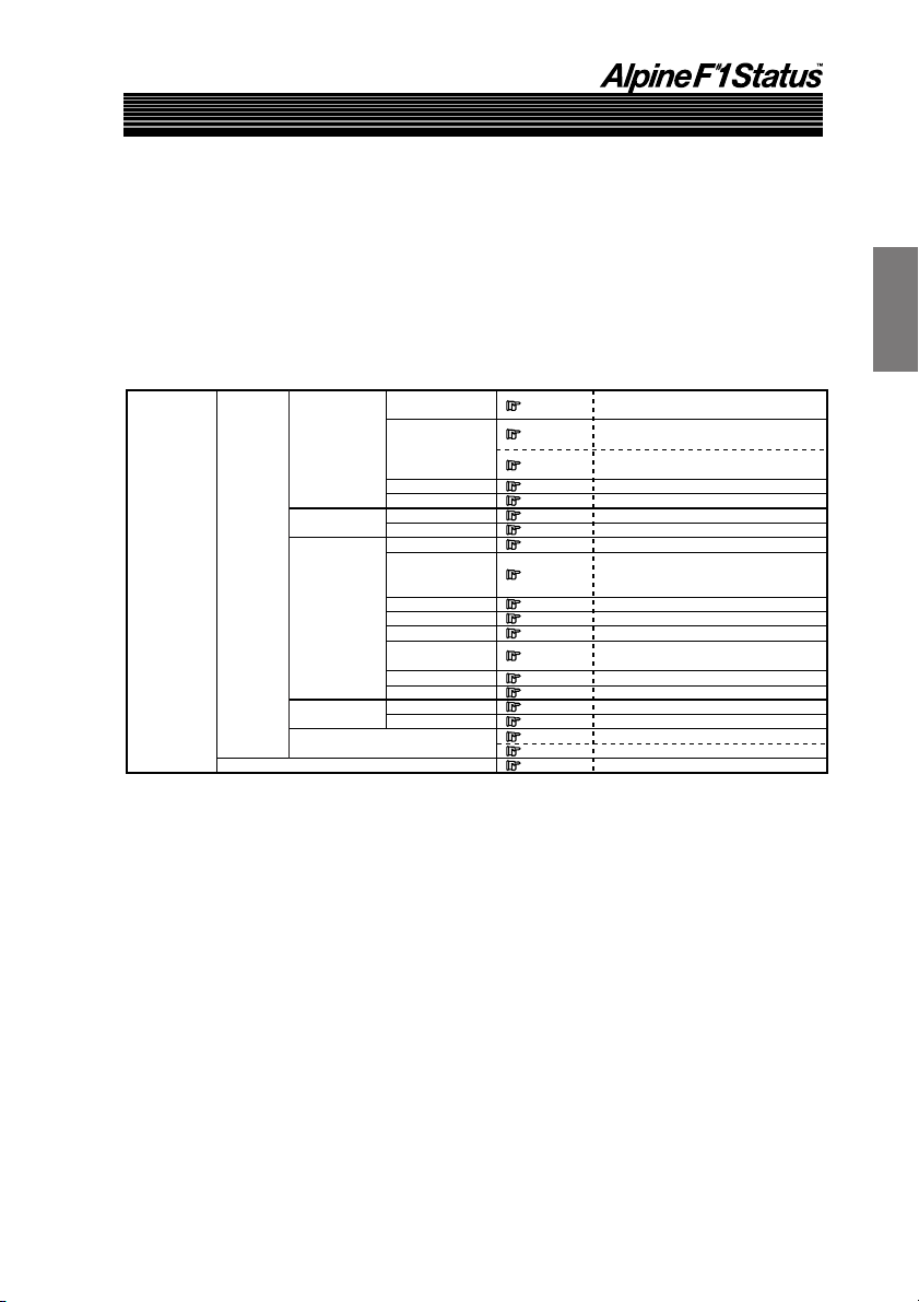
Operating the PXI-H990
The PXI-H990 is operated from the head unit with which it is used.
These operating instructions describe operation with the head unit; both from the unit itself and
from the remote control unit.
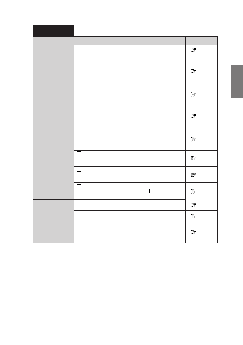
• The operation for the PXI-H990 is performed from the head unit setup operation.
See the reference page in the following chart for the head unit setting/adjustment operation
method. The following is displayed on the head unit display.
Crossover adjustment/Switching the phase
Performing time correction automatically
(Automated Time Correction)
Performing time correction manually
(Time Correction)
Equalizer adjustments
Using the Road Equalizer function
MX settings
Adjusting the DVD level
Adjusting the acoustic image
Mixing the Bass Sound of the Center
Channel with the Sound of the Front Left
and Right Channels
Mixing bass sound to the rear channel
Achieving powerful high volume sound
Adjusting the speaker levels
Outputting the Front Channel Signals
from the Rear Channels
6.1-Channel Settings
PCM Output Settings
Setting the speakers
Speaker setup
Storing settings in the memory
Calling out stored values
External input settings
M.M.Manager
AP SETUP
AUX SETUP
MOBILE.S.MGR
MEDIA.S.MGR
MULTI.CH.MGR
SP SETUP
PRESET
CROSSOVER
TCR
EQ
Road EQ
MX
DVD LEVEL
BI PHANTOM
C.BASS SPLIT
REAR MIX
LISTEN MODE
OUTPUT LEVEL
REAR FILL
6.1CH MODE
PCM OUT MODE
SP SELECT
Dolby SP
Page 42
Page 21
Page 26
Page 32
Page 15
Page 47
Page 74
Page 60
Page 63
Page 66
Page 72
Page 57
Page 69
Page 77
Page 80
Page 7
Page 53
Page 93
Page 96
Page 91
• If operating with the head unit’s buttons, view the head unit’s display. If operating from the
remote control supplied with the head unit, view the monitor’s display (sold separately) used in
the system. If a monitor is not used in your system, operate from the head unit only.
• For how to connect, refer to the guide for installation and connections.
5-EN
Page 10
Basic Operation
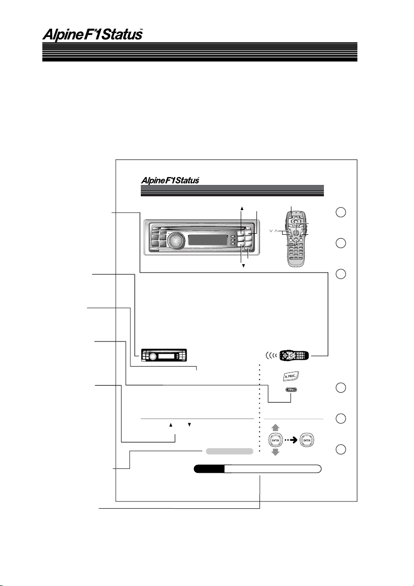
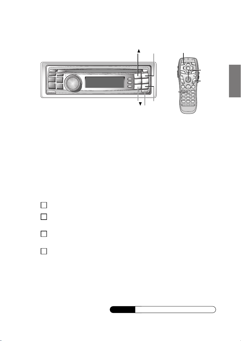
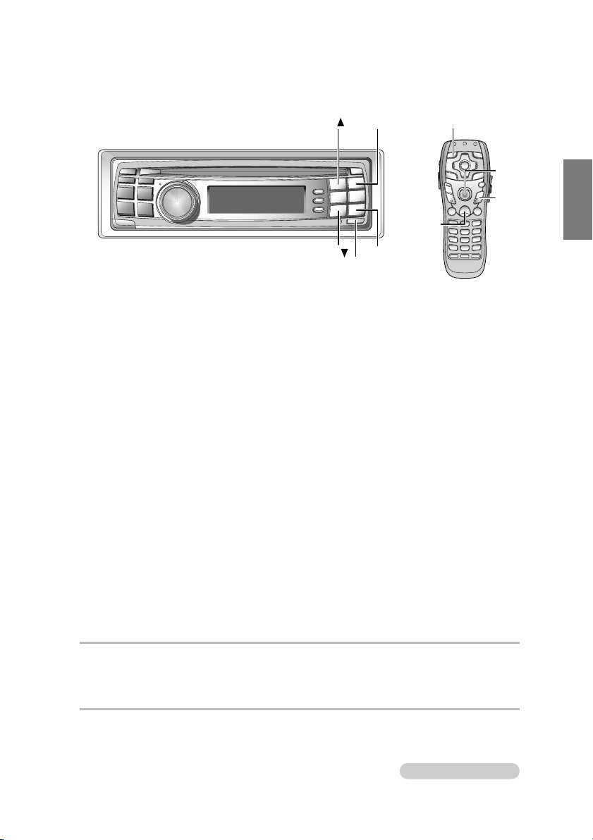
Using This Manual
The PXI-H990 is operated from the head unit with which it is used.
These operating instructions describe operation from both the DVI-9990 head unit and from the
RUE-4196 remote control unit included with the head unit. When operating the main unit with the
remote control supplied with the head unit, change the selector switch on the rear side of remote
control to the “H/U” side.
Using the multi-channel function
/
RETURN
A. PROC.
ENTER/
Joystick
MENU
SETUP
Remote control icon
Indicates operations
performed with the
remote control supplied
with the head unit (only
when connected to
a monitor, sold
separately).
Head unit icon
Indicates operations
performed from the
head unit.
Button name
Buttons to be
operated are
indicated in bold.
3Sec icon
Indicates that the
specified button
should be pressed
and held for over
3 seconds.
Separately sold
monitor display
If you combine with a
separately sold monitor
and operate with the
remote control supplied
with the head unit, the
selected item is
displayed on the screen,
as opposed to being
displaying on the
head unit.
Continued (Next page)
Indicates that the
description of the
operation continues
on the next page.
Supplement icon
Indicates that there is
supplementary information
on another page.
1( )
2(ENT)
F
•
SETUP
5( )
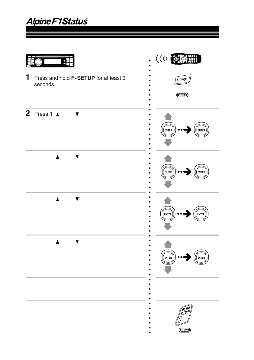
Adjusting the acoustic image (BI PHANTOM)
To achieve sound with a sense of presence, the center speaker must be placed directly in front of the
driver’s seat and the passenger’s seat. With this function, the center channel information is
distributed to the left and right speakers. This creates an acoustic image simulating a center speaker
directly in front of the listener. (This only has an effect when “DOLBY PL II MOVIE” or “Neo:6
CINEMA” is selected at “PCM Output Settings” (page 80). The audio source must be playing back
Dolby Digital or DTS signals with center channel information.)
• Avoid stopping, pausing, switching the disc, cueing, fast-forwarding or switching the
audio channel of the player while making this adjustment.
1
Press and hold F
seconds.
2
Press 1 ( ) or 5 ( ), select “M.M.Manager
[Multi Media Manager]”, then press
60
-
EN
•
SETUP for at least 3
Continued
Supplement
.
2 (ENT)
See page 88 for supplementary information.
6-EN
Page 11
RETURN
A. PROC.
ENTER/
Joystick
MENU
SETUP
1( )
5( )
F
•
2(ENT)
SETUP
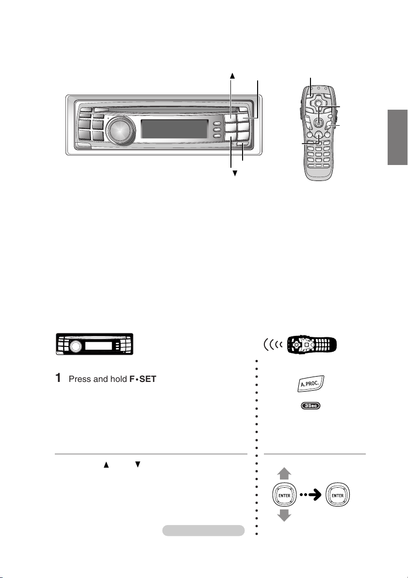
Turning the power on and off
This unit does not have a power switch. The head unit to which the unit is connected, controls its
power. In order to protect the speakers when the power is first switched on or when the head unit is
reset, no sound is produced until system is selected in the next item “Setting the speakers”. Set the
following item “Setting the speakers”.
Setting the speakers (SP SELECT)
First, make the system and speaker settings. The system settings are required before any other
settings can be made. To prevent speaker damage, make sure the selected system and speaker
connections are in correct (see the instruction manual). It is necessary to check the speaker
connection before selecting the system.
Turn off speaker channels that are not in use.
1 Press and hold F
•
SETUP for at least 3
seconds.
2 Press 1 ( ) or 5 ( ), select “M.M.Manager
[Multi Media Manager]”, then press 2 (ENT).
Continued
○○○○○○○○○○○○○○○○○○○○○○○
7-EN
Page 12
Basic Operation
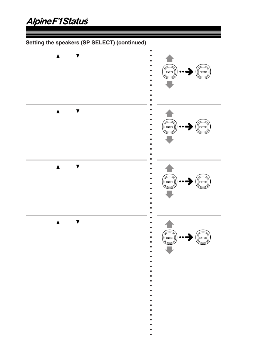
Setting the speakers (SP SELECT) (continued)
3 Press 1 ( ) or 5 ( ), select “AP SETUP”, then
press 2 (ENT).
4 Press 1 ( ) or 5 ( ), select “SP SETUP
[Speaker Setup]”, then press 2 (ENT).
5 Press 1 ( ) or 5 ( ), select “SP SELECT
[Speaker Select]”, then press 2 (ENT).
○○○○○○○○○○○○○○○○○○○○○○○○○○○○○○○○○○○○○○○○○○○○○○○○○○○○○○○○○○○
6 Press 1 ( ) or 5 ( ), select “SYSTEM SEL
[System Select]”, then press 2 (ENT).
8-EN
Page 13
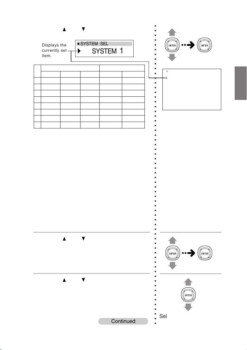
7 Press 1 ( ) or 5 ( ), select the system, then
press 2 (ENT).
Displays the
currently set
item.
SYSTEM SEL
SYSTEM
1
○○○○○○○○○○○○○○○○○○○○○○○○○○○○○○○○○○○○○○○○○○○○○○○○○○○○○○○○○○○○○○○○
When one PXI-H990 is connected
CH-1
CH-2
CH-3
CH-4
CH-5
CH-6
CH-7
CH-8
SYSTEM 1
F TW L
F TW R
F WF L*1
F WF R*1
REAR L
REAR R
FRNT C
SUBW.
SYSTEM 2
F TW L
F TW R
F MID L*2
F MID R*2
F WF L*2
F WF R*2
SUBW. 1
SUBW. 2
SYSTEM 3
FRNT L*1
FRNT R*1
FRNT C
SUBW. 1
REAR L
REAR R
REAR C
SUBW. 2
When two PXI-H990 are connected
SYSTEM 4 (FRONT)
F TW L
F TW R
F MID L*2
F MID R*2
F WF L*2
F WF R*2
F TW C
F WF C
SYSTEM 4 (REAR)
R TW L
R TW R
R WF L
R WF R
R TW C
R WF C
SUBW. 1
SUBW. 2
* 1 There is no OFF setting.
* 2 It is not possible to turn both “MID” and “WF” off.
If one is set to “OFF”, the other cannot be set to
“OFF”.
• Do not connect the tweeter (TW) to the channel
without “TW” indicated in the table above. If
connected, the speaker may be damaged.
• For SYSTEM 1, REAR TW cannot be connected.
• For SYSTEM 3, FRONT TW and REAR TW cannot
be connected.
•“SYSTEM 4” cannot be selected when only one unit
of the PXI-H990 is connected. Also, “SYSTEM 1” to
“SYSTEM 3” cannot be selected when two units of
the PXI-H990 are connected.
Next make the speaker settings.
SYSTEM SEL
System 1
System 2
System 3
System 4
8 Press 1 ( ) or 5 ( ), select “CH SELECT
[Channel Select]”, then press 2 (ENT).
9 Press 1 ( ) or 5 ( ), select the speaker that is
not connected, then press 2 (ENT).
Continued
Select a speaker that is
not connected.
9-EN
Page 14
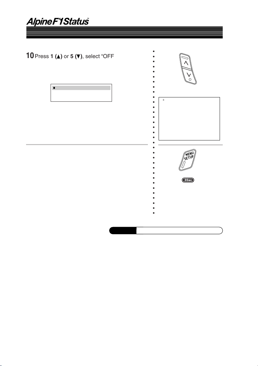
Basic Operation
Setting the speakers (SP SELECT) (continued)
10
Press 1 ( ) or 5 ( ), select “OFF”, then press
2 (ENT).
Repeat steps 9 and 10 and switch off all
unconnected speakers.
○○○○○○○○○○○○○○○○○○○○○○○○○○○○○○○○○
CH SELECT
F TW
11
Once the settings are completed, press and
hold F
• SETUP for at least 3 seconds.
• Press 6 (RTN) or RETURN on the remote control in
the setting mode to return to the previous item.
L OFF
Supplement
Switch ON/OFF.
CH SELECT
Front TW Left ON
Front TW Right ON
Front WF Left ON
Front WF Right ON
Rear Left ON
Rear Right ON
Front Center ON
Subwoofer ON
See page 11 for supplementary information.
10-EN
Page 15

Supplementary
information
TITLE
Setting the speakers
(SP SELECT)
This page includes supplementary information for pages 5 to 10.
Please refer to these pages.
Description
The operations performed with the remote control unit in
step 1 can also be performed by pressing MENU (SETUP)
for at least 3 seconds, moving the joystick up or down to
select “AP SETUP”, then pressing the joystick.
Related page
Page 7
11-EN
Page 16

Automatic Adjustments
Preparations for automatic adjustments
The PXI-H990 is equipped with two automatic adjustment functions: “Road Equalizer” and
“Automated Time Correction”.
The preparations described below must be made in order to perform these automatic adjustments.
After making these preparations, refer to “Automatic adjustments (Using the Road Equalizer
function)” (page 15) and “Performing time correction automatically (Automated Time Correction)”
(page 21) to perform the respective automatic adjustments.
• When performing automatic adjustment, set the head unit to the TUNER mode before adjusting.
1 Check that the head unit defeat mode is off.
2 Adjust the head unit and amplifier levels.
Head unit:
Set the balance and fader to “center”.
Front, rear and center amplifiers:
Set the amp gains to “center” or “normal” to start. If there are no rear
speakers, check that the rear speakers are turned off. (See page 7.) Gain
levels may be changed if you are not satisfied with the automatic results.
Make the gain changes and return the automatic adjustment.
Subwoofer amplifier:
Set the amplifier gain to “center” or “normal”. If the subwoofer is located in
the trunk or a remote place (for example at the very back of a station
wagon), adjust the subwoofer to increase the volume several steps.
Speaker Crossovers:
Set the crossovers for all the speakers in the system that will require them.
See page 42, “Crossover adjustment/Switching the phase”, for more
information on setting the crossovers.
12-EN
Page 17
3 Connect the included microphone to the PXI-H990.
Refer to the Installation manual.
• When combined with a separately sold monitor that is Road EQ compatible and the Road
Equalizer function are used, the separately sold monitor’s built-in microphone can be
used.
• When connecting two PXI-H990 units, connect the microphone to both units. In this case,
the built-in microphone in the separately sold monitor cannot be used.
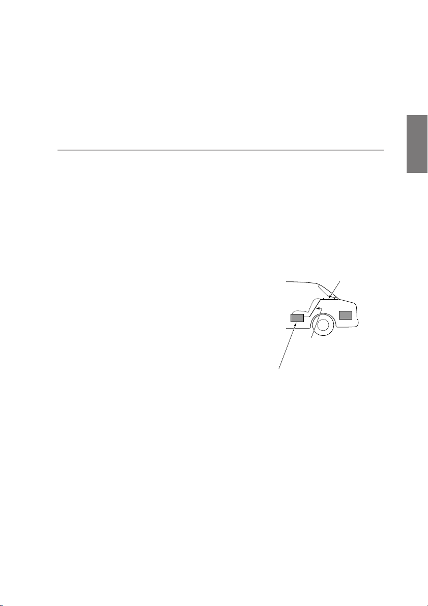
4 Secure the microphone in place.
Failure to fix the microphone securely in place may result in distortion or
improper acoustic positioning. The microphone must be mounted very
securely so the bass frequencies will not vibrate it. For example, fasten
using the fitting included with the sun visor, etc.
• The adjustment differs according to the position
of the microphone. Search for the position at which
the desired sound quality can be achieved.
• The proper adjustments cannot be achieved if the
subwoofer is located in the trunk and the trunk and
cabin are separated by a metal sheet. Either move
the subwoofer into the cabin or open a hole in the
rear tray to join the two spaces. (This is not necessary
if the partition is not a metal sheet.)
• Do not disconnect the microphone during the automatic adjustment procedure.
If the partition is a metal sheet,
open a hole in the rear tray.
If you encounter a problem,
consult your authorized dealer.
Is the partition a
metal sheet?
Or move the subwoofer
into the cabin.
13-EN
Page 18
Automatic Adjustments
Preparations for automatic adjustments (continued)
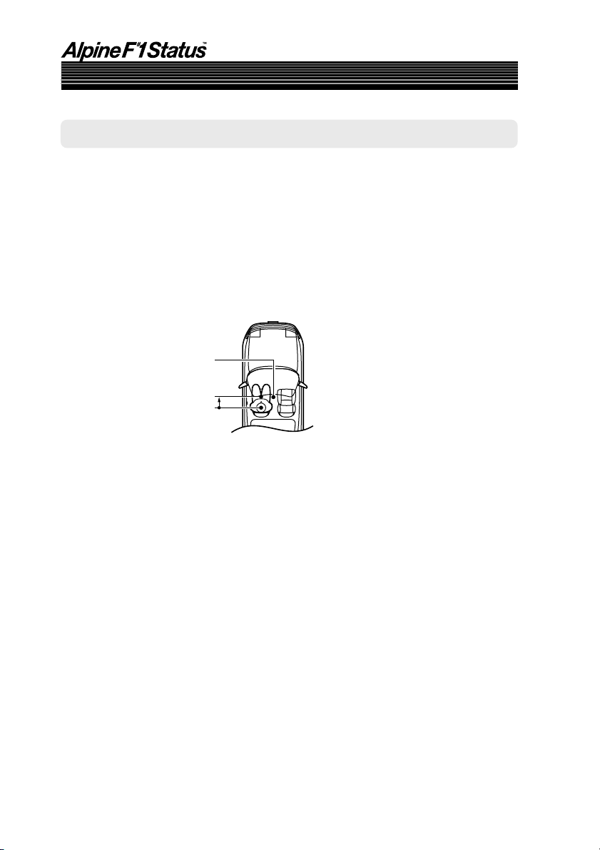
Hints on using the Road Equalizer function
The Road Equalizer compensates for constantly changing noise, so always keep the microphones
connected. The following three places are recommended to place the microphones. Also, when
combining with the separately sold monitor, the built-in microphone can be used.
A Ceiling directly above the listening position (driver’s seat position – More accurate
compensation for the driver.)
B Sun visor (driving seat position)
C Base of rearview mirror (position for both driver’s and passenger’s seats)
C
B
A
• If connecting two PXI-H990 units, place the microphones connected to each unit in the
same places.
14-EN
Page 19
RETURN
A. PROC.
ENTER/
Joystick
MENU
SETUP
1( )
2(ENT)
5( ) 6(RTN)
F
•
SETUP
Using the Road Equalizer function
Road Equalizer (REAL-TIME OPTIMIZED ADAPTIVE DRIVING EQUALIZER) is a function
that automatically adjusts the equalizer settings during driving according to the amount of road
noise.
To use Road Equalizer, first connect the microphone. (See “Preparations for automatic adjustments”
on page 12.)
When used in combination with a separately sold monitor that is Road EQ compatible, the
monitor’s built-in microphone can be used, in which case the microphone included with the PXIH990 cannot be used. When connecting two PXI-H990 units, the built-in microphone in the
separately sold monitor cannot be used.
Perform the Road Equalizer operations in the following order:
Selection of microphone
A
↓
Measurement of frequency
B
response inside the vehicle
↓
Selection of Road Equalizer setting
C
(ON/OFF)
↓
Selection of mode
D
• In order to avoid the effects of exterior noises during measurement of frequency response
inside the vehicle, move the car to a quiet location and change the ignition switch to the
ACC position.
Due to vibration, correct measurement data may not be acquired, so do not switch on the
engine. However, be aware that the battery may be drained.
• Do not remove the microphones when using Road Equalizer.
Supplement
See page 25 for supplementary information.
15-EN
Page 20
Automatic Adjustments
Using the Road Equalizer function (continued)
○○○○○○○○○○○○○○○○○○○○○○○○○○○○○○○○○○○○○○○○○○○○○○○○○○○○○○○○○
1
Press and hold F
seconds.
2 Press 1 ( ) or 5 ( ), select “M.M.Manager
[Multi Media Manager]”, then press 2 (ENT).
3 Press 1 ( ) or 5 ( ), select “AP SETUP”, then
press 2 (ENT).
4 Press 1 ( ) or 5 ( ), select “MOBILE.S.MGR
[Mobile Sound Manager]”, then press 2
(ENT).
•
SETUP for at least 3
5 Press 1 ( ) or 5 ( ), select “Road EQ”, then
press 2 (ENT).
6 Perform the operations from page 17 to 20.
7 Press and hold
seconds to end.
F
•
SETUP
for at least 3
16-EN
Page 21
A
Selecting the Microphone
1) In the Road Equalizer mode, press 1 ( ) or 5
(
), select “MIC SELECT [Microphone
Select]”, then press 2 (ENT).
2) Press 1 ( ) or 5 ( ), select the microphone,
then press 2 (ENT).
MIC SELECT
EXTERNAL MIC
○○○○○○○○○○○○○○○○○○○○○○○○○○○○○○○○○○○○○○○○○○
EXTERNAL MIC [External Microphone]:
Set this when using the microphone included
with the PXI-H990.
MONITOR MIC [Monitor Internal
Microphone]:
Set this when using in combination with a
separately sold monitor (TMI-M990) and using
the monitor’s built-in microphone.
Next measure the frequency response inside
the vehicle.
• Press 6 (RTN) or RETURN on the remote control in
the setting mode to return to the previous item.
Supplement
See page 25 for supplementary information.
MIC SELECT
External Microphone
Monitor Internal Microphone
Displays the currently
set item.
17-EN
Page 22
Automatic Adjustments
Using the Road Equalizer function (continued)
B
Measuring the Frequency Response Inside the Vehicle
○○○○○○○○○○○○○○○○○○○○○○○○○○○○○○○○○○○○○○○○○○○
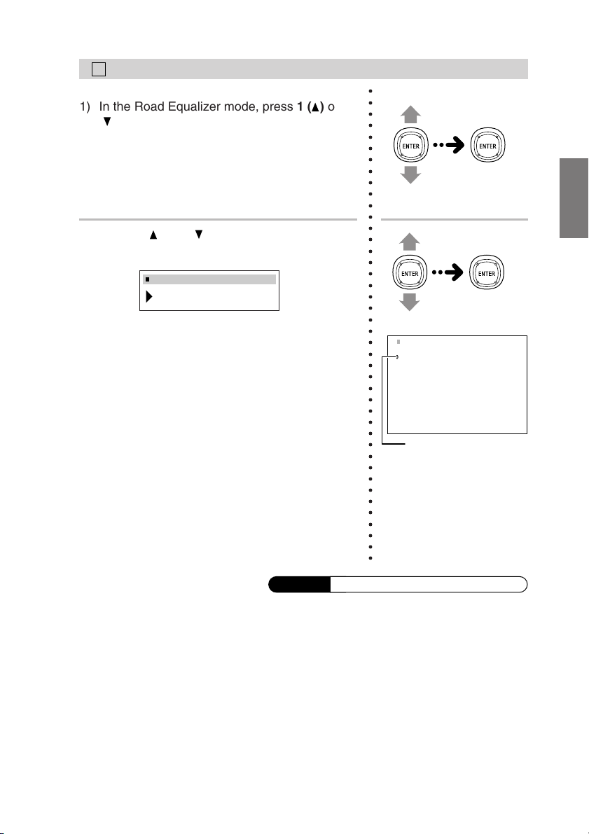
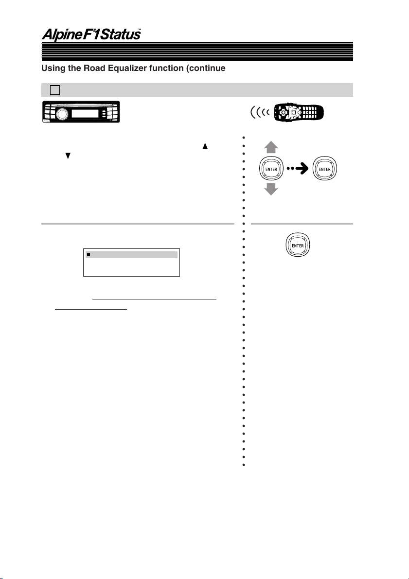
1) In the Road Equalizer mode, press 1 ( ) or
5 (
), select “R.EQ SETUP [Auto Road EQ
Setup]”, then press 2 (ENT).
2) Press 2 (ENT).
R.EQ SETUP
START
Measuring begins after a 10 second countdown, so
within 10 seconds.
Measuring is canceled if 2 (ENT) is pressed
during measuring or during the countdown.
Measuring ends after about 8 minutes. After
measuring is complete, “COMPLETE” is
displayed, press 2 (ENT) to clear measuring
mode and press 6 (RTN).
• Press 6 (RTN) or RETURN on the remote control in
•“NO MIC ERR” is displayed when a microphone has
leave the car and close the door
the setting mode to return to the previous item.
not been connected. Press 2 (ENT) to clear the
display.
18-EN
After measuring is
complete, “Complete” is
displayed, press
ENTER to clear
measuring mode and
press RETURN.
•“NO MIC ERR” is
displayed when a
microphone has not been
connected. Press ENTER
to clear the display.
Page 23
C
Turning Road Equalizer On and Off
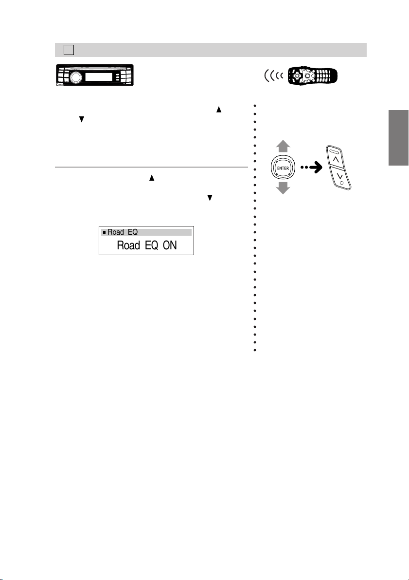
1) In the Road Equalizer mode, press 1 ( ) or
5 (
), select “Road EQ ON/OFF”.
2) When OFF, press 1 ( ) after pressing
2 (ENT) to switch ON.
To switch from ON to OFF, press 5 (
pressing 2 (ENT).
Road EQ
) after
Road EQ ON
Select “OFF” if you do not want to use the
Road Equalizer function.
• Press 6 (RTN) or RETURN on the remote control in
the setting mode to return to the previous item.
○○○○○○○○○○○○○○○○○○○○○○○○○○○○○○○○
19-EN
Page 24
Automatic Adjustments
Using the Road Equalizer function (continued)
D
Selecting the Mode
○○○○○○○○○○○○○○○○○○○○○○○○○○○○○○○○○○○○○○
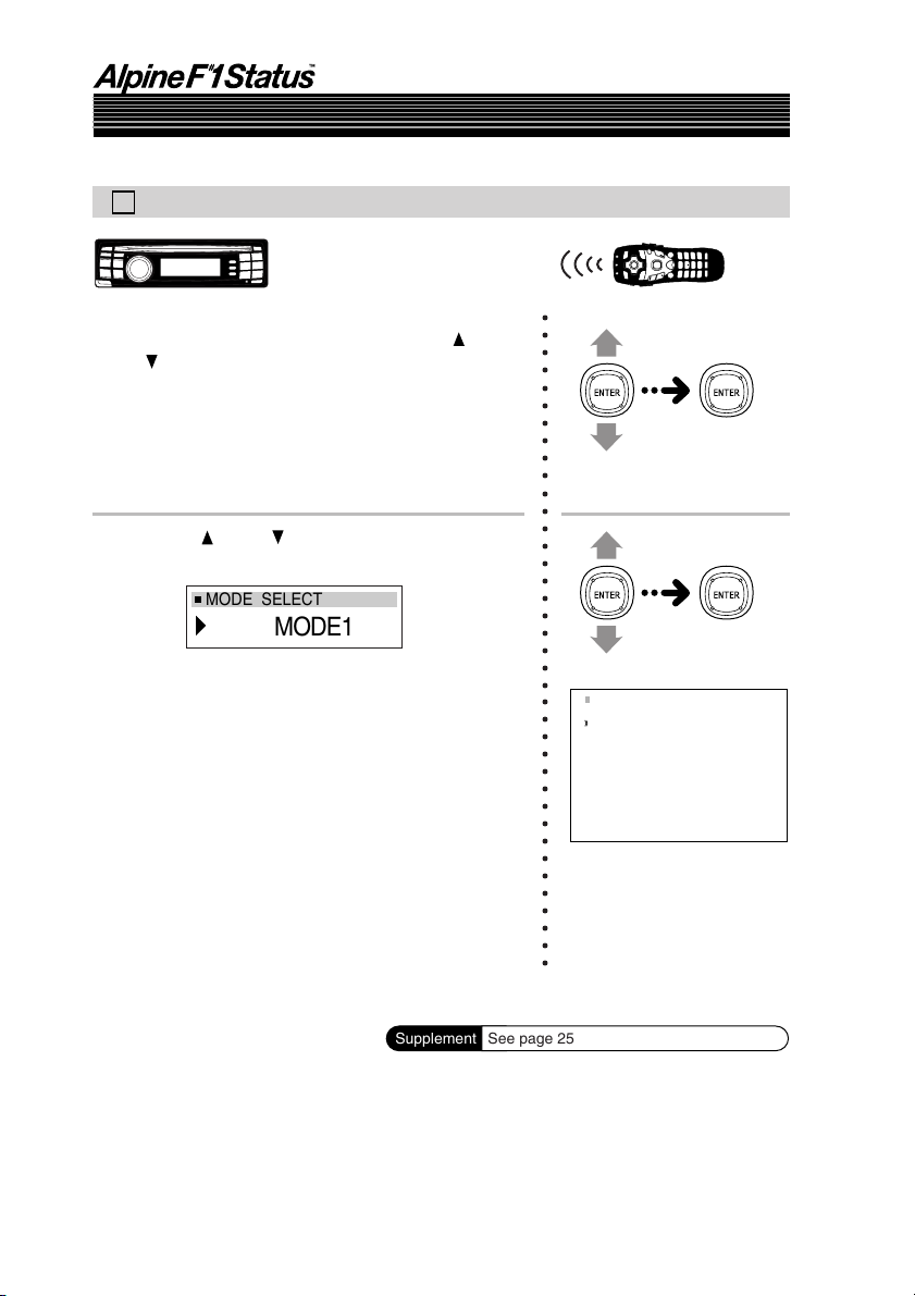
1) In the Road Equalizer mode, press 1 ( ) or
5 (
), select “MODE SELECT”, then press
2 (ENT).
2) Press 1 ( ) or 5 ( ), select the desired mode,
then press 2 (ENT).
MODE SELECT
MODE1
MODE1 [Mode1]: Low compensation mode.Suit-
able for a quiet car.
MODE2 [Mode2]: Higher compensation mode.
MODE3 [Mode3]: Highest compensation mode. Use
when driving in a very noisy car.
• Press 6 (RTN) or RETURN on the remote control in
the setting mode to return to the previous item.
Supplement
20-EN
MODE SELECT
Mode1
Mode2
Mode3
See page 25 for supplementary information.
Page 25
1( )
2(ENT)
5( ) 6(RTN)
F
•
SETUP
RETURN
A. PROC.
ENTER/
Joystick
MENU
SETUP
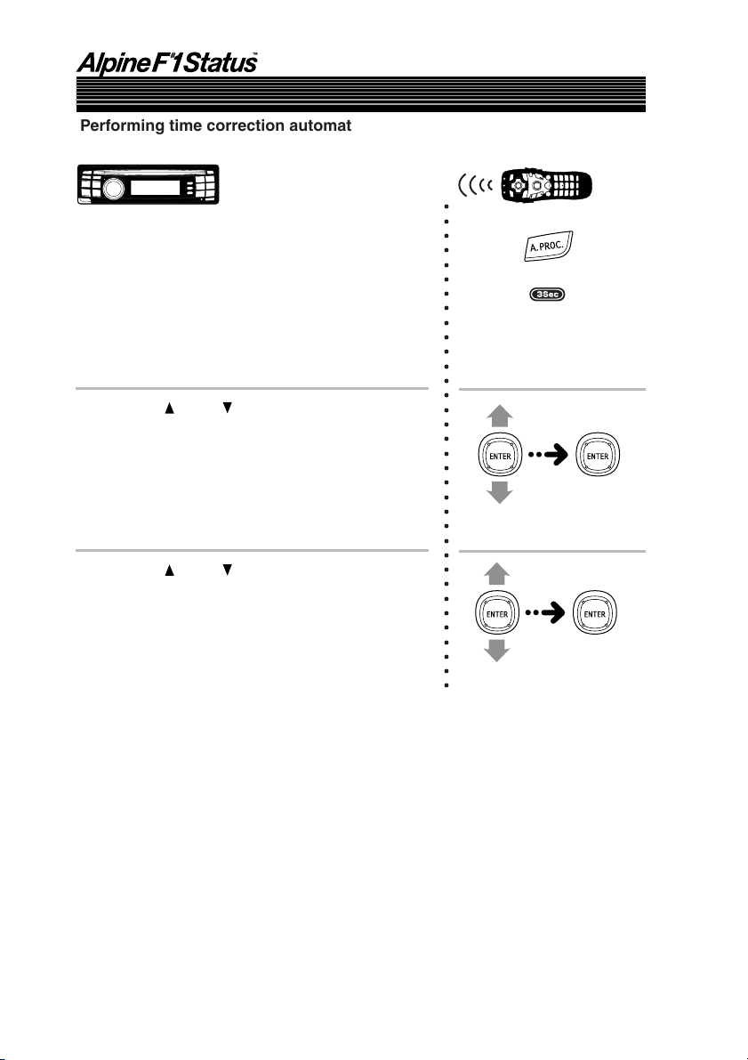
Performing time correction automatically
(Automated Time Correction)
Due to the particular conditions inside the vehicle, there is a major difference between the distances
of the various speakers and the listening position. This function uses the included measurement
microphone to automatically measure and analyze the distances between the speakers and the
listening position and perform the optimum time correction.
• Preparations must be made before performing the automatic adjustment procedure. Refer
to page 12.
• The PXI-H990’s automatic adjustments take into account the delay time between the time
at which the signals are input to the speakers until the sound is output. This does not
correspond to the actual distance.
• With the automatic adjustments, the average delay time within the speakers’ playable
frequency range is measured. Measurements may not be possible when using special
speakers or in special playback environments. If this is the case, perform the adjustments
manually.
• The AUTO TCR operation cannot be performed if the included microphone is not
connected.
• When performing automatic adjustment, set the head unit to the TUNER mode before
adjusting.
1 Before starting the automatic adjustment procedure, park the vehicle in a
quiet place to avoid the effects of external sounds.
2 Set the vehicle’s key to the ACC position.
Do not start the engine. The vibrations may make it impossible to achieve
the proper adjustment values.
3 Adjust the volume.
Adjust the volume to “-50dB” by performing the volume adjustment opera-
tion on the head unit.
Continued
21-EN
Page 26
Automatic Adjustments
Performing time correction automatically (Automated Time Correction)
(continued)
○○○○○○○○○○○○○○○○○○○○○○○○○○○○○○○○○○
4 Press and hold F • SETUP for at least 3
seconds.
5 Press 1 ( ) or 5 ( ), select “M.M.Manager
[Multi Media Manager]”, then press 2 (ENT).
6 Press 1 ( ) or 5 ( ), select “AP SETUP”, then
press 2 (ENT).
22-EN
Page 27
7 Press 1 ( ) or 5 ( ), select “MOBILE.S.MGR
[Mobile Sound Manager]”, then press
2 (ENT).
8 Press 1 ( ) or 5 ( ), select “TCR [Time
Correction]”, then press 2 (ENT).
9 Press 1 ( ) or 5 ( ), select “AUTO TCR [Auto
Time Correction]”, then press 2 (ENT).
• Check that “TCR” is set to “ON”.
If it is set to “OFF”, set it to “ON”, referring to
“Performing time correction manually” on page 26.
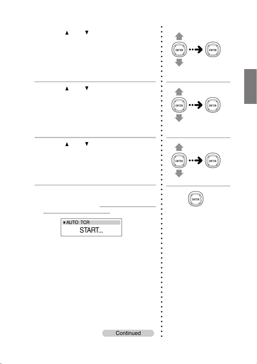
10
Press 2 (ENT).
Automatic adjustment begins after a 10
second countdown, so
the door within 10 seconds.
leave the car and close
○○○○○○○○○○○○○○○○○○○○○○○○○○○○○○○○○○○○○○○○○○○○○○○○○○○○○○○○○○○○○○○○
AUTO TCR
START...
Automatic adjustment is canceled if 2 (ENT) is
pressed during the countdown.
Continued
23-EN
Page 28
Automatic Adjustments
Performing time correction automatically (Automated Time Correction)
(continued)
The automatic adjustment procedure consists
of the operations described below and
requires about a few minutes to be completed.
Perform the time correction.
When the automatic adjustment is completed, a system reset will be performed.
Strong sounds are produced during the
automatic adjustment procedure (except for
TW, Sub WF). These sounds can be heard
outside the vehicle. Be sure to park the
vehicle in a place where the sound will not be
a nuisance.
○○○○○○○○○○○○○○○○○○○○○○○○○○○○○○○○○○○○○○○○○○○○○○○○○
•“NO MIC ERR” is displayed when a microphone has
not been connected. Press 2 (ENT) to clear the
display.
11
When the system reset is completed, return to
the car and check that the setting value of the
Automated Time Correction is reflected.
If the setting value is not changed, the
microphone may not receive sound, the
speaker may be damaged, the connection
and wiring may be a malfunction.
To store the settings, refer to “Storing settings
in the memory” (page 93).
• Press 6 (RTN) or RETURN on the remote control in
the setting mode to return to the previous item.
Supplement
•“NO MIC ERR” is
displayed when a
microphone has not been
connected. Press ENTER
to clear the display.
See page 25 for supplementary information.
24-EN
Page 29
Supplementary
information
TITLE
Using the Road
Equalizer function
Performing time
correction automatically
(Automated Time
Correction)
This page includes supplementary information for pages 12 to 24.
Please refer to these pages.
Description
Connect both microphones if two PXI-H990s are connected.
If the microphone does not pick up the sound or the
speakers are not working or are connected or wired
improperly, the automatic adjustments are not performed
and a warning message is displayed.
Check the various speakers then perform the automatic
adjustments again.
When Road Equalizer is ON and 96 kHz or 192 kHz DVDAudio playback is set, down sampling to 48 kHz will take
place automatically and the DVD will be played.
When any speaker is switched on or off following the
adjustment of Road Equalization and Road Equalization is
ON, Road Equalization will automatically be switched OFF.
When a change has been made to the speaker settings,
redo the setup from the measurement step.
The operations performed with the remote control unit in
step 1 can also be performed by pressing and holding
MENU (SETUP) for at least 3 seconds, moving the joystick
up or down to select “AP SETUP”, then pressing the joystick.
B
Measuring the Frequency Response Inside the Vehicle
Note that using for extended periods of time without turning
on the engine may wear down the battery.
C
Turning Road Equalizer On and Off
The mode is automatically set to “ON” when the frequency
response inside the vehicle is measured.
D
Selecting the Mode
Cannot be selected when OFF is set in “C Turning Road
Equalizer On and Off”.
Connect both microphones if two PXI-H990s are connected.
Note that using for extended periods of time without turning
on the engine may wear down the battery.
The operations performed with the remote control unit in
step 4 can also be performed by pressing and holding
MENU (SETUP) for at least 3 seconds, moving the joystick
up or down to select “AP SETUP”, then pressing the joystick.
Related page
Page 15
Page 15
Page 15
Page 15
Page 16
Page 18
Page 19
Page 20
Page 21
Page 21
Page 22
25-EN
Page 30

Settings/Adjustments
Performing time correction manually (Time
Correction)
Though sufficient correction can be achieved with the “Automated Time Correction” automatic
adjustments, it is also possible for the user to calculate the correction values and make the
adjustments manually. This manual adjustment requires sufficient knowledge and experience,
however, so we suggest you have it performed at your authorized Alpine dealer.
1 Check that the head unit defeat mode is off.
2 Sit in the listening position (the driver’s seat, for example) and measure the
distance (in meters) between your head and the various speakers.
3 Calculate the difference in distance between the farthest speaker and the
other speakers.
L = (distance of farthest speaker) – (distance of other speakers)
26-EN
Page 31

4 Divide the distances calculated for the different speakers by the speed of
5.1ms
sound (343 m/s temperature 20°C).
This value is the time correction value for the different speakers.
• The speed of sound fluctuates according to the temperature. The accurate speed of sound
can be achieved with the formula shown below.
Speed of sound = 331.45 + C × T
C: 0.607
T: Temperature (°C)
• Concrete examples
1. Calculating the time correction value for the front left speaker on the diagram below.
Conditions:
Distance between farthest speaker and listening position: 2.25 m (88-3/4")
Distance between front left speaker and listening position: 0.5 m (20")
Calculation: L = 2.25 m (88-3/4") – 0.5 m (20") = 1.75 m (68-3/4")
Compensation time = 1.75 ÷ 343 × 1000 = 5.1 (ms)
In other words, setting the time correction value for the front left speaker to 5.1 (ms)
sets a virtual distance matching the distance to the farthest speaker.
0.5m
2.25m
The sound is uneven because the distance
between the listening position and the
different speakers is different.
The difference in the distance between the
front left and rear right speakers is 1.75
meters (68-3/4").
Time correction eliminates the difference
between the time required for the sound
from the different speakers to reach the
listening position.
Setting the time correction of the front left
speaker to 5.1 ms makes it possible to
coordinate the distance from the listening
position to the speaker.
Continued
27-EN
Page 32

Settings/Adjustments
Performing time correction manually (Time Correction) (continued)
1( )
5( ) 6(RTN)
5 Press and hold F • SETUP for at least 3
seconds.
6 Press 1 ( ) or 5 ( ), select “M.M.Manager
[Multi Media Manager]”, then press 2 (ENT).
F
•
/
RETURN
A. PROC.
ENTER/
Joystick
MENU
SETUP
2(ENT)
SETUP
○○○○○○○○○○○○○○○○○○○○○○○○○○○○○○○○
7 Press 1 ( ) or 5 ( ), select “AP SETUP”, then
press 2 (ENT).
28-EN
Page 33

8 Press 1 ( ) or 5 ( ), select “MOBILE.S.MGR
[Mobile Sound Manager]”, then press
2 (ENT).
9 Press 1 ( ) or 5 ( ), select “TCR [Time
Correction]”, then press 2 (ENT).
10
Press 1 ( ) or 5 ( ), select “TCR ON/OFF
[Time Correction ON/OFF]”.
11
When OFF, press 1 ( ) after pressing 2 (ENT)
to switch TCR ON [Time Correction ON].
When ON, after pressing 2 (ENT), press 5 (
to switch TCR OFF [Time Correction OFF].
○○○○○○○○○○○○○○○○○○○○○○○○○○○○○○○○○○○○○○○○○○○○○○○○○○○○○○○○○○○○○○○○
)
12
After selecting ON in the above procedure,
press 1 (
) or 5 ( ), select “CH MODE
[Channel Mode]”, then press 2 (ENT).
Continued
Switch ON/OFF.
TCR
Channel Select
Adjust
Channel Mode
Auto Time Correction
Time Correction ON
29-EN
Page 34

Settings/Adjustments
Performing time correction manually (Time Correction) (continued)
13
Press 1 ( ) or 5 ( ), select “L or R” or “L+R”,
then press 2 (ENT).
L or R: Different adjustment values can be
set for the left and right channels.
L+R: Sets the same adjustment values for
the left and right channels.
When “L+R” is selected.
1) Press 1 (
) or 5 ( ), select either the Lch
or Rch settings to validate and press
2 (ENT).
L->L+R: Make the present Lch settings
valid and set L/R with the same
adjustment values.
R->L+R: Make the present Rch settings
valid and set L/R with the same
adjustment values.
2) Press 6 (RTN).
14
Press 1 ( ) or 5 ( ), select “CH SELECT
[Channel Select]”, then press 2 (ENT).
○○○○○○○○○○○○○○○○○○○○○○○○○○○○○○○○○○○○○○○○○○○○○○○○○○○○○○○○○○○
15
Press 1 ( ) or 5 ( ), select the desired
channel, then press 2 (ENT).
The channels that can be selected are
different depending on the system setting
(page 9).
30-EN
CH SELECT
Front TW Left
Front TW Right
Front WF Left
Front WF Right
Rear Left
Rear Right
Front Center
Subwoofer
Page 35

16
Press 1 ( ) or 5 ( ), select “ADJUST
[Adjust]”, then press 2 (ENT).
17
Press 2 (ENT), and press 1 ( ) or 5 ( ),
adjust time correction (0.00~20.00ms, 0.05ms
step), then press 6 (RTN).
○○○○○○○○○○○○○○○○○○○○○○○○○○○○○○○○○○○○○○○○○○○○○○○○○○○○○○○○○○
0. 00
)
ms
ADJ(F TW R
18
To adjust another channel, repeat steps 14 to
17.
19
Once the settings are completed, press and
hold F
• SETUP for at least 3 seconds.
ADJ ( F TW L
Delay Time 0.15ms
)
• Press 6 (RTN) or RETURN on the remote control in
the setting mode to return to the previous item.
Supplement
See page 51 for supplementary information.
31-EN
Page 36

Settings/Adjustments
A. PROC.
RETURN
/
MENU
SETUP
ENTER/
Joystick
1( )
2(ENT)
5( ) 6(RTN)
F
•
SETUP
Equalizer adjustments
The PXI-H990 is equipped with a graphic equalizer and parametric equalizer. You can set the
Equalizer to whatever values you want.
Graphic equalizer
The level of the front, rear and center channels can be adjusted separately for 31 bands and the
subwoofer can be adjusted for 10 bands (a total of 206 bands) to achieve the desired sound field.
Parametric equalizer
The frequency bands of the graphic equalizer are fixed. This makes it very difficult to correct for
undesired peaks and dips at specific frequencies. The parametric equalizer’s center frequency can
be tuned these specific frequencies. Then, the bandwidth (Q) and level are fine-tuned, independently, to make the necessary corrections. The parametric equalizer function is an advanced tool for
serious audiophiles.
• This adjustment is easier when test signals such as pink noise are used. For information
on test signals, consult your authorized Alpine dealer.
• Check the playable frequency ranges of the connected speakers before making the
equalizer adjustments. If the speaker’s playable frequency range is 55 Hz to 30 kHz, for
example, adjusting the 40 Hz or 20 Hz band has no effect. Additionally, you may overload
and damage the speakers.
• Once the settings have been made, we recommend storing them in the memory. See page
93 for instructions.
• If you combine with a head unit (DVI-9990) or monitor (TMI-M990) (both sold separately), you can adjust the equalizer while viewing the adjusted contents on the monitor
screen. (See “Equalizer adjustment (when DVI-9990/TMI-M990 is connected)”, page 99).
• MP3 and WMA recorded Discs with a sampling frequency of 32 kHz cannot be compensated above 16 kHz.
32-EN
Page 37

1 Check that the head unit defeat mode is off.
2
Press and hold F
seconds.
•
SETUP for at least 3
3 Press 1 ( ) or 5 ( ), select “M.M.Manager
[Multi Media Manager]”, then press 2 (ENT).
4 Press 1 ( ) or 5 ( ), select “AP SETUP”, then
press 2 (ENT).
5 Press 1 ( ) or 5 ( ), select “MOBILE.S.MGR
[Mobile Sound Manager]”, then press
2 (ENT).
○○○○○○○○○○○○○○○○○○○○○○○○○○○○○○○○○○○○○○○○○○○○○○○○○○○○○
6 Press 1 ( ) or 5 ( ), select “EQ [Equalizer]”,
then press 2 (ENT).
7 Press 1 ( ) or 5 ( ), select “EQ TYPE SEL
[EQ Type Select]”, then press 2 (ENT).
Continued
33-EN
Page 38

Settings/Adjustments
Equalizer adjustments (continued)
8 Press 1 ( ) or 5 ( ), select the Equalizer type,
then press 2 (ENT).
○○○○○○○○○○○○○○○○○○○○○○○○○○○○○○○○○○○○○○○○○○○○○○○○○○○○○○○○○○○○
GRAPHIC. EQ
[Graphic EQ]
PARAMET. EQ
[Parametric EQ]
EQ OFF
[EQ Off]
9 Press 1 ( ) or 5 ( ), select “CH MODE
[Channel Mode]”, then press 2 (ENT).
10
Press 1 ( ) or 5 ( ), select “L or R” or “L+R”,
then press 2 (ENT).
L or R: Different adjustment values can be
set for the left and right channels.
L+R: Sets the same adjustment values for
the left and right channels.
EQ TYPE SEL
Graphic EQ
Parametric EQ
EQ Off
When “L+R” is selected.
1) Press 1 (
) or 5 ( ), select either the Lch
or Rch settings to validate and press
2 (ENT).
L->L+R: Make the present Lch settings
valid and set L/R with the same
adjustment values.
R->L+R: Make the present Rch settings
valid and set L/R with the same
adjustment values.
2) Press 6 (RTN).
See page 35 for “Graphic Equalizer Adjustments”.
See page 37 for “Parametric Equalizer Adjustments”.
34-EN
Page 39

Graphic Equalizer Adjustments
11
Press 1 ( ) or 5 ( ), select “CH SELECT
[Channel Select]”, then press 2 (ENT).
12
Press 1 ( ) or 5 ( ), select the desired
channel, then press 2 (ENT).
The channels that can be selected depend on
the system settings (page 9).
13
Press 1 ( ) or 5 ( ), select “BAND [Band]”,
then press 2 (ENT).
○○○○○○○○○○○○○○○○○○○○○○○○○○○○○○○○○○○○○○○○○○○○○○○○○○○○○○○○
14
Press 1 ( ) or 5 ( ), select the frequency,
then press 2 (ENT).
Adjustable frequencies
Front /Rear/Center : 20Hz~20kHz
(in steps of 1/3 octave)
Subwoofer : 20Hz~160Hz
(in steps of 1/3 octave)
BAND
FREQ 20HZ
Continued
BAND
Frequency 20Hz
Frequency 25Hz
Frequency 31.5Hz
Frequency 40Hz
Frequency 50Hz
Frequency 63Hz
Frequency 80Hz
Frequency 100Hz
Frequency 125Hz
35-EN
Page 40

Settings/Adjustments
Graphic Equalizer Adjustments (continued)
15
Press 1 ( ) or 5 ( ), select “ADJUST
[Adjust]”, then press 2 (ENT).
16
Press 2 (ENT), and press 1 ( ) or 5 ( ),
adjust the level (±9 dB, in steps of 0.5 dB),
then press 6 (RTN).
○○○○○○○○○○○○○○○○○○○○○○○○○○○○○○○○○○○○○○○○○○○○○○○○○○○○○○○○○○○
ADJ(20Hz
17
To adjust another frequency band, repeat
steps 13 to 16.
18
To adjust other channels, repeat steps 11 to
17.
19
Once the settings are completed, press and
hold F
• SETUP for at least 3 seconds.
)
LEVEL
0. 0
dB
(Level adjustment)
)
ADJ ( 20Hz
Level 1.5dB
• Press 6 (RTN) or RETURN on the remote control in
the setting mode to return to the previous item.
36-EN
Page 41

Parametric Equalizer Adjustments
11
Press 1 ( ) or 5 ( ), select “CH SELECT
[Channel Select]”, then press 2 (ENT).
12
Press 1 ( ) or 5 ( ), select the desired
channel, then press 2 (ENT).
The channels that can be selected depend on
the system settings (page 9).
13
Press 1 ( ) or 5 ( ), select “BAND [Band]”,
then press 2 (ENT).
14
Press 1 ( ) or 5 ( ), select the band, then
press 2 (ENT).
Adjustable bands
Front/Rear/Center :10 Bands
Subwoofer :2 Bands
BAND
BAND
1
○○○○○○○○○○○○○○○○○○○○○○○○○○○○○○○○○○○○○○○○○○○○○○○○○○○○○○○○○
BAND
BAND 1
BAND 2
BAND 3
BAND 4
BAND 5
BAND 6
BAND 7
BAND 8
BAND 9
15
Press 1 ( ) or 5 ( ), select “ADJUST
[Adjust]”, then press 2 (ENT).
Continued
37-EN
Page 42

Settings/Adjustments
Parametric Equalizer Adjustments (continued)
16
Press 1 ( ) or 5 ( ), select the mode “FREQ
[Frequency]”, then press 2 (ENT).
○○○○○○○○○○○○○○○○○○○○○○○○○○○○○○○○○○○○○○○○○○○○○○○○○○○○○○○○○
17
Press 1 ( ) or 5 ( ), select the frequency,
then press 2 (ENT).
For the adjustable frequencies, see page 109.
ADJ(BAND 1
)
FREQ 28 Hz
• It is not possible to adjust the frequencies of adjacent
bands within 4 steps.
18
Press 1 ( ) or 5 ( ), select “Q [Q-Factor]”,
then press 2 (ENT).
19
Press 1 ( ) or 5 ( ), select the bandwidth “Q”,
then press 2 (ENT).
The bandwidth can be adjusted in six steps:
0.5, 1, 2, 3, 4 and 5
Q
0. 5
)
ADJ(BAND 1
ADJ ( BAND 1
Frequency 31.5Hz
Q-Factor 0.5
Level 1.5dB
ADJ ( BAND 1
Frequency 31.5Hz
Q-Factor 0.5
Level 1.5dB
)
)
38-EN
Page 43

20
Press 1 ( ) or 5 ( ), select “LV [Level]”,
then press 2 (ENT).
○○○○○○○○○○○○○○○○○○○○○○○○○○○○○○○○○○○○○○○○○○○○○○○○○○○○○○○
21
Press 1 ( ) or 5 ( ), adjust the level (±9dB
0.5dB step), then press 2 (ENT).
LV
)
0. 0
dB
ADJ(BAND 1
22
To adjust another band, after pressing
6 (RTN), repeat steps 13 to 21.
23
To adjust other channels, after pressing
6 (RTN), repeat steps 11 to 22.
24
Once the settings are completed, press and
hold F
• SETUP for at least 3 seconds.
ADJ ( BAND 1
Frequency 31.5Hz
Q-Factor 0.5
Level 1.5dB
)
• Press 6 (RTN) or RETURN on the remote control in
the setting mode to return to the previous item.
Supplement
See page 51 for supplementary information.
39-EN
Page 44

Settings/Adjustments
Crossover network
The PXI-H990 is equipped with an active dividing network allowing the bands to be split before
amplification by the power amplifier.
Because of this, there is no need for a passive network between the speakers and amplifiers and the
amplifiers are fully independent, thus eliminating the problem of interference and making it
possible to achieve the optimum acoustic space by dividing the playback frequencies in a way
suited to the capacities of the speakers.
This adjustment requires special knowledge and experience. Should problems arise, please see your
authorized Alpine dealer.
Adjust the high pass filter (H.P.F.) and low pass filter (L.P.F.) and set the slope
(filter response attenuation slope) for the different bands.
Make the adjustments according to the playable frequency ranges and
frequency responses of the connected speakers.
FRONT
FRONT TW
FRONT MID
FRONT WF
REAR
REAR TW
REAR WF
FRONT C
FRONT C TW
FRONT C WF
REAR C
REAR C TW
REAR C WF
SUBWOOFER
Frequency Adjustment Bandwidth
20Hz〜18kHz
1kHz〜18kHz
20Hz〜18kHz
20Hz〜18kHz
20Hz〜18kHz
1kHz〜18kHz
20Hz〜18kHz
20Hz〜18kHz
1kHz〜18kHz
20Hz〜18kHz
20Hz〜18kHz
1kHz〜18kHz
20Hz〜18kHz
20Hz〜160Hz
Cutoff
(1/6 Octave Steps)
H.P.F. L.P.F. H.P.F. L.P.F.
22Hz〜20kHz
1.1kHz〜20kHz
22Hz〜20kHz
22Hz〜20kHz
22Hz〜20kHz
1.1kHz〜20kHz
22Hz〜20kHz
22Hz〜20kHz
1.1kHz〜20kHz
22Hz〜20kHz
22Hz〜20kHz
1.1kHz〜20kHz
22Hz〜20kHz
22Hz〜180Hz
−6/−12/−18/−24/−30dB/
−6/−12/−18/−24/−30dB
−6/−12/−18/−24/−30dB/
−6/−12/−18/−24/−30dB/
−6/−12/−18/−24/−30dB/
−6/−12/−18/−24/−30dB
−6/−12/−18/−24/−30dB/
−6/−12/−18/−24/−30dB/
−6/−12/−18/−24/−30dB
−6/−12/−18/−24/−30dB/
−6/−12/−18/−24/−30dB/
−6/−12/−18/−24/−30dB
−6/−12/−18/−24/−30dB/
−6/−12/−18/−24/−30dB/
Filter OFF
Filter OFF
Filter OFF
Filter OFF
Filter OFF
Filter OFF
Filter OFF
Filter OFF
Filter OFF
Filter OFF
Slope Adjustment
−6/−12/−18/−24/−30dB/
−6/−12/−18/−24/−30dB/
−6/−12/−18/−24/−30dB/
−6/−12/−18/−24/−30dB/
−6/−12/−18/−24/−30dB/
−6/−12/−18/−24/−30dB/
−6/−12/−18/−24/−30dB/
−6/−12/−18/−24/−30dB/
−6/−12/−18/−24/−30dB/
−6/−12/−18/−24/−30dB/
−6/−12/−18/−24/−30dB/
−6/−12/−18/−24/−30dB/
−6/−12/−18/−24/−30dB/
−6/−12/−18/−24/−30dB
Filter OFF
Filter OFF
Filter OFF
Filter OFF
Filter OFF
Filter OFF
Filter OFF
Filter OFF
Filter OFF
Filter OFF
Filter OFF
Filter OFF
Filter OFF
40-EN
Page 45

Output signals with these frequencies
Slope adjustment
20 Hz 10 kHz
H.P.F. cutoff frequency
L.P.F. cutoff frequency
Slope off
The H.P.F. setting cannot be the same as or exceed the L.P.F. setting for that
channel.
• The crossover network is a filter that divides specific frequency bands.
• The high pass filter is a filter that cuts frequencies below a certain frequency (bass frequencies)
and lets through treble frequencies.
• The low pass filter is a filter that cuts frequencies above a certain frequency (treble frequencies)
and lets through bass frequencies.
• The slope is a value expressing the attenuation of the signal in decibels when the frequency is
increased or decreased by one octave.
• The higher the slope value, the steeper the slope.
• If the slope is set to “OFF”, the signal does not pass through the filter, so there is no effect.
• In order to protect the speakers, the front high range high pass filter cannot be turned off (the
slope cannot be set to “OFF”).
For the same reason, the subwoofer low pass filter cannot be turned off (the slope cannot be set
to “OFF”).
• Tweeters may be damaged if low frequency signals are input to them.
• MP3 and WMA recorded Discs with a sampling frequency of 32 kHz cannot be compensated
above 16 kHz.
41-EN
Page 46

Settings/Adjustments
/
RETURN
A. PROC.
ENTER/
Joystick
MENU
SETUP
1( )
2(ENT)
5( ) 6(RTN)
F
•
SETUP
Crossover adjustment/Switching the phase
○○○○○○○○○○○○○○○○○○○○○○○○○○○○○○○○○○○○
1
Press and hold F
seconds.
•
SETUP for at least 3
2 Press 1 ( ) or 5 ( ), select “M.M.Manager
[Multi Media Manager]”, then press 2 (ENT).
42-EN
Page 47

3 Press 1 ( ) or 5 ( ), select “AP SETUP”, then
press 2 (ENT).
4 Press 1 ( ) or 5 ( ), select “MOBILE.S.MGR
[Mobile Sound Manager]”, then press
2 (ENT).
5 Press 1 ( ) or 5 ( ), select “CROSSOVER
[Crossover]”, then press 2 (ENT).
6 Press 1 ( ) or 5 ( ), select “CH MODE
[Channel Mode]”, then press 2 (ENT).
○○○○○○○○○○○○○○○○○○○○○○○○○○○○○○○○○○○○○○○○○○○○○○○○○○○○○○○○○○○○○○○○
7
Press 1 ( ) or 5 ( ), select “L or R” or “L+R”,
then press 2 (ENT).
L or R: Different adjustment values can be
set for the left and right channels.
L+R: Sets the same adjustment values for
the left and right channels.
When “L+R” is selected.
1) Press 1 (
or Rch settings to validate and press
2 (ENT).
L->L+R: Make the present Lch settings
R->L+R: Make the present Rch settings
2) Press 6 (RTN).
) or 5 ( ), select either the Lch
valid and set L/R with the same
adjustment values.
valid and set L/R with the same
adjustment values.
Continued
43-EN
Page 48

Settings/Adjustments
Crossover adjustment/Switching the phase (continued)
8
Press 1 ( ) or 5 ( ), select “CH SELECT
[Channel Select]”, then press 2 (ENT).
9
Press 1 ( ) or 5 ( ), select the channel
(speaker) to be adjusted, then press 2 (ENT).
The channels that can be selected depend on
the system settings (page 9).
10
Press 1 ( ) or 5 ( ), select “ADJUST
[Adjust]”, then press 2 (ENT).
11
Press 1 ( ) or 5 ( ), select “LOW.P [Low Pass
Freq]” or “HI.P [High Pass Freq]”, then press
2 (ENT).
○○○○○○○○○○○○○○○○○○○○○○○○○○○○○○○○○○○○○○○○○○○○○○○○○○○○○○○○○○
• Adjust the crossover network HI/LOW by operating
the steps 11 to 14.
12
Press 1 ( ) or 5 ( ), select the desired cutoff
frequency (crossover point), then press
2 (ENT).
ADJ(F WF L
LOW. P
• The bands that can be adjusted differ according to the
channel (speaker).
)
400
44-EN
ADJ ( F TW L
Low Pass Freq 20KHz
Low Pass Slope OFF
High Pass Freq 1KHz
High Pass Slope -18dB/oct
Level 0dB
Phase 0
)
Page 49

13
Press 1 ( ) or 5 ( ), select “LOW.SL [Low
Pass Slope]” or “HI.SL [High Pass Slope]”,
then press 2 (ENT).
○○○○○○○○○○○○○○○○○○○○○○○○○○○○○○○○○○○○○○○○○○○○○○○○○○○○○○○○○○○○○○○○
14
Press 1 ( ) or 5 ( ), adjust the slope, then
press 2 (
ENT
).
ADJ(F WF L
)
LOW. SL OFF
15
Press 1 ( ) or 5 ( ), select “LEVEL [Level]”,
then press 2 (ENT).
16
Press 1 ( ) or 5 ( ), adjust the level
(–12dB~0dB, 1dB steps), then press 2 (ENT).
ADJ(F WF L
L
17
Press 1 ( ) or 5 ( ), select “PHASE [Phase]”,
then press 2 (ENT).
)
EVEL 0dB
ADJ ( F TW L
Low Pass Freq 20KHz
Low Pass Slope OFF
High Pass Freq 1KHz
High Pass Slope -18dB/oct
Level 0dB
Phase 0
ADJ ( F TW L
Low Pass Freq 20KHz
Low Pass Slope OFF
High Pass Freq 1KHz
High Pass Slope -18dB/oct
Level 0dB
Phase 0
)
)
18
Press 1 ( ) or 5 ( ), switch the phase, then
press 2 (ENT).
0° 180°
ADJ(F WF L
)
PHASE
0
Continued
ADJ ( F TW L
Low Pass Freq 20KHz
Low Pass Slope OFF
High Pass Freq 1KHz
High Pass Slope -18dB/oct
Level 0dB
Phase 0
)
45-EN
Page 50

Settings/Adjustments
Crossover adjustment/Switching the phase (continued)
19
To adjust another channel, after pressing
6 (RTN), repeat steps 8 to 18.
20
Once the settings are completed, press and
hold F
• SETUP for at least 3 seconds.
• Press 6 (RTN) or RETURN on the remote control in
the setting mode to return to the previous item.
Hint for adjusting the subwoofer
• If the subwoofer is installed on the rear deck, setting
a gentle L.P.F. slope (for example –6 dB/oct.) makes
the sound localization more to the rear. This can also
affect the acoustic localization of the front.
Hints for adjusting the high range
• Depending on the speaker, inputting low frequency
component signals (about 2 kHz or less) with the
H.P.F. adjustment could result in distortion. If so,
set a steep slope (for example –30 dB/oct.).
When doing so, adjust so that the mid and high range
sounds do not separate.
• Normally use with the L.P.F. off. If the high range is
too strong, we recommend adjusting for a gentle
slope.
○○○○○○○○○○○○○○○○○○○○○○○○○○○○○○○○○○○○○○○○○○○○○○○○○○○○○○○○
Hint for adjusting the low range
• When a subwoofer is connected and you are using a
speaker with a low range of under 10 or 12 cm (3-15/
16" or 4-3/4"), setting the low range H.P.F. to “OFF”
can result in distortion when low frequency
components are input.
If so, set the H.P.F. slope to a value suited for the
speaker’s frequency response.
Supplement
See page 51 for supplementary information.
46-EN
Page 51

RETURN
A. PROC.
ENTER/
Joystick
MENU
SETUP
1( )
5( )
F
•
2(ENT)
SETUP
MX settings
MX (Media Xpander) makes vocals or instruments sound distinct regardless of the music source.
The FM radio and CD will be able to reproduce the music clearly even in cars with a lot of road
noise. When the head unit’s music source is switched, the settings automatically switch to the MX
settings you have set.
1 Check that the head unit defeat mode is off.
2
Press and hold F
•
SETUP for at least 3
seconds.
3 Press 1 ( ) or 5 ( ), select “M.M.Manager
[Multi Media Manager]”, then press 2 (ENT).
Continued
○○○○○○○○○○○○○○○○○○○○
47-EN
Page 52

Settings/Adjustments
MX settings (continued)
4 Press 1 ( ) or 5 ( ), select “AP SETUP”, then
press 2 (ENT).
5 Press 1 ( ) or 5 ( ), select “MEDIA.S.MGR
[Media Sound Manager]”, then press 2 (ENT).
6 Press 1 ( ) or 5 ( ), select “MX [Media
Xpander]”, then press 2 (ENT).
7
Press 1 ( ) or 5 ( ), select “MX ON/OFF”.
○○○○○○○○○○○○○○○○○○○○○○○○○○○○○○○○○○○○○○○○○○○○○○○○○○○○○○○○○○○
8
When OFF, press 1 ( ) after pressing
2 (ENT) to switch MX ON.
To switch from ON to OFF, press 5 (
pressing 2 (ENT) and MX is switched OFF.
48-EN
) after
MX
Media Select
MX Select
MX OFF
Page 53

9 If set to ON, press 1 ( ) or 5 ( ), select
“MEDIA SEL [Media Select]”, then press
2 (ENT).
10
Press 1 ( ) or 5 ( ), select the source
(medium) to be set, then press 2 (ENT).
11
Press 1 ( ) or 5 ( ), select “MX SELECT [MX
Select]”, then press 2 (ENT).
○○○○○○○○○○○○○○○○○○○○○○○○○○○○○○○○○○○○○○○○○○○○○○○○○○○○○○○○○○○○○○○○
Continued
49-EN
Page 54

Settings/Adjustments
MX settings (continued)
12
Press 1 ( ) or 5 ( ), select the desired mode,
then press 2 (ENT).
MX SELECT
MX
1
When “OFF” is selected, the MX effect is
turned off.
FM: MX1 to 5 and OFF
The medium to high frequencies become
more clear, and produces well balanced
sound in all the bands.
CD: MX1 to 5 and OFF
CD mode processes a large quantity of data.
This data is used to reproduce the sound
cleanly by making use of the data quantity.
CMP.MEDIA [Compressed Media] (MP3, WMA,
etc.)/XM: MX1 to 5 and OFF
This corrects information that was omitted at
the time of compression. This reproduces a
well-balanced sound close to the original.
DVD-VIDEO [DVD-Video]/VIDEO-CD [Video-CD]:
MX1 to 5, OFF
The dialogues of movies are played with
greater clarity.
AUX: MX1 to 5, OFF
Choose the MX mode (MX1: Low compres-
sion rate to MX5: High compression rate) that
corresponds to the media compression rate
connected.
○○○○○○○○○○○○○○○○○○○○○○○○○○○○○○○○○○○○○○○○○○○○○○○○○○○○○○○○
MX SELECT
MX 1
MX 2
MX 3
MX 4
MX 5
Effect OFF
13
To make the settings for another source
(medium), repeat steps 9 to 12.
14
Once the settings are completed, press and
hold F
• SETUP for at least 3 seconds.
• Press 6 (RTN) or RETURN on the remote control in
the setting mode to return to the previous item.
Supplement
50-EN
See page 51 for supplementary information.
Page 55

Supplementary
information
TITLE
Performing time
correction manually
(Time Correction)
Equalizer adjustments
Crossover
adjustment/
Switching the phase
MX settings
This page includes supplementary information for pages 26 to 50.
Please refer to these pages.
Description
Time correction cannot be performed for speakers set to
“OFF” at the speaker settings (page 7).
In reality the time difference depends not only on the
difference in physical distance but also on the delay time
between the time at which the signals are input to the
speakers until the sound is output. This delay time depends
on the speaker, and may also be somewhat affected on how
the speaker is mounted on the vehicle. After making the
setting, we recommend listening to the sound and fineadjusting if necessary.
After making the settings, we recommend storing them in
the memory. See page 93 for instructions.
The operations performed with the remote control unit in
step 5 can also be performed by pressing and holding
MENU (SETUP) for at least 3 seconds, moving the joystick
up or down to select “AP SETUP”, then pressing the joystick.
The equalizer adjustments cannot be made for speakers set
to “OFF” at the speaker settings (page 7).
After making the settings, we recommend storing them in
the memory. See page 93 for instructions.
The operations performed with the remote control unit in
step 2 can also be performed by pressing and holding
MENU (SETUP) for at least 3 seconds, moving the joystick
up or down to select “AP SETUP”, then pressing the joystick.
When playing back 96kHz or 192kHz DVD-Audio using the
graphic EQ, the audio signal is automatically down sampled
to 48kHz and played back.
The crossover network adjustments cannot be made for
speakers set to “OFF” at the speaker settings (page 7).
The operations performed with the remote control unit in
step 1 can also be performed by pressing and holding
MENU (SETUP) for at least 3 seconds, moving the joystick
up or down to select “AP SETUP”, then pressing the joystick.
After making the settings, we recommend storing them in
the memory. See page 93 for instructions.
The DVD Audio MX setting remains at “OFF”.
The operations performed with the remote control unit in
step 2 can also be performed by pressing and holding
MENU (SETUP) for at least 3 seconds, moving the joystick
up or down to select “AP SETUP”, then pressing the joystick.
After making the settings, we recommend storing them in
the memory. See page 93 for instructions.
When playing back 96kHz or 192kHz DVD-Audio with MX is
ON, the audio signal is automatically down sampled to
48kHz and played back.
Related page
Page 26
Page 26
Page 26
Page 28
Page 32
Page 32
Page 33
Page 34
Page 42
Page 42
Page 42
Page 47
Page 47
Page 47
Page 48
51-EN
Page 56

Using the multi-channel function
Adjustment procedure for multi-channel function
Make the adjustments described below in order to reproduce Dolby Digital and DTS sound with
greater accuracy.
Adjustment procedure
1
2
3
4
5
the Front Left and Right Channels (C.BASS SPLIT) (Page 63)
Mixing bass sound to the rear channel (REAR MIX) (Page 66)
6
Achieving powerful high volume sound (LISTEN MODE) (Page 72)
7
8
9
Speaker setup (Dolby SP) (Page 53)
Adjusting the speaker levels (OUTPUT LEVEL) (Page 57)
Adjusting the acoustic image (BI PHANTOM) (Page 60)
Mixing the Bass Sound of
the Center Channel with the Sound of
Outputting the Front Channel Signals
from the Rear Channels (REAR FILL) (Page 69)
Adjusting the DVD level (DVD LEVEL) (Page 74)
6.1-Channel Settings (6.1CH MODE) (Page 77)
10
11
• In case of combining the Automatic adjustments etc.
We recommend to make the Automatic adjustments before the multi-channel function
adjustments.
PCM Output Settings (PCM OUT MODE) (Page 80)
Storing settings in the memory (Page 93)
52-EN
Page 57

/
RETURN
A. PROC.
ENTER/
Joystick
MENU
SETUP
1( )
2(ENT)
5( ) 6(RTN)
F
•
SETUP
Speaker setup (Dolby SP)
The PXI-H990 can be set according to the playable frequency range of your speakers.
Check the playable frequency range of the speakers (not including the subwoofer) before perform-
ing this operation to verify whether the speakers can play low frequencies.
• Avoid stopping, pausing, switching the disc, cueing, fast-forwarding or switching the
audio channel of the player while making this adjustment. The setting is canceled if
the decode mode is switched.
○○○○○○○○○○○○○○○○○○○○○○○○○○○
1 Press and hold F • SETUP for at least 3
seconds.
2 Press 1 ( ) or 5 ( ), select “M.M.Manager
[Multi Media Manager]”, then press 2 (ENT).
Continued
53-EN
Page 58

Using the multi-channel function
Speaker setup (Dolby SP) (continued)
3 Press 1 ( ) or 5 ( ), select “AP SETUP”, then
press 2 (ENT).
4 Press 1 ( ) or 5 ( ), select “SP SETUP
[Speaker Setup]”, then press 2 (ENT).
5 Press 1 ( ) or 5 ( ), select “Dolby SP [Dolby
Speaker Setup]”, then press 2 (ENT).
6 Press 1 ( ) or 5 ( ), select “CH SELECT
[Channel Select]”, then press 2 (ENT).
○○○○○○○○○○○○○○○○○○○○○○○○○○○○○○○○○○○○○○○○○○○○○○○○○○○○○○○○○○
7
Press 1 ( ) or 5 ( ), select the speaker to be
set, then press 2 (ENT).
FRONT REAR FRONT CENTER
SUBWOOFER
REAR CENTER
54-EN
CH SELECT
Front
Rear
Front Center
Rear Center
Subwoofer
Page 59

8 Press 1 ( ) or 5 ( ), select “SETUP [Setup]”,
then press 2 (ENT).
9 Press 1 ( ) or 5 ( ), select the speaker type,
then press 2 (ENT).
○○○○○○○○○○○○○○○○○○○○○○○○○○○○○○○○○○○○○○○○○○○○○○○○○○○○○○○○○○○○○○○○
LARGE SMALL OFF
*1
(Subwoofer is only ON/OFF.)
LARGE:
When a speaker that can play low frequencies
is connected
SMALL:
When a speaker that cannot play low frequencies is connected
OFF:
When no speaker is connected
*1: It is not possible to set the front speakers
to “OFF”.
• When the front speaker is SMALL, center
speaker is LARGE and the subwoofer is OFF,
do not set the rear speakers to OFF or
SMALL.
• No sound will be produced from the rear
speaker when it is set to off, even when the
rear center speaker is set to LARGE or
SMALL.
SETUP
LARGE
SMALL
OFF
Continued
55-EN
Page 60

Using the multi-channel function
Speaker setup (Dolby SP) (continued)
10
To adjust another speaker, repeat steps 6 to
9.
Cut-off frequency setting
Set the cut-off frequency to restrict the
playback when the speaker settings are set to
“SMALL”. Perform this setting after selecting
the speaker setting of every speaker.
○○○○○○○○○○○○○○○○○○○○○○○○○○○○○○○○○○○○○○○○○○○○○○○
1) On the mode Dolby SP, press 1 (
5 (
), select “CUTOFF [Cutoff]”, then press
2 (ENT).
2) Press 2 (ENT), press 1 (
the cutoff frequency, then press 6 (RTN).
Settable frequencies
80Hz/100Hz/120Hz/160Hz/200Hz
11
Once the settings are completed, press and
hold F
• SETUP for at least 3 seconds.
• Press 6 (RTN) or RETURN on the remote control in
the setting mode to return to the previous item.
) or 5 ( ), select
Supplement
) or
See page 88 for supplementary information.
56-EN
Page 61

/
RETURN
A. PROC.
ENTER/
Joystick
MENU
SETUP
1( )
2(ENT)
5( ) 6(RTN)
F
•
SETUP
Adjusting the speaker levels (OUTPUT LEVEL)
Use the test tones output from the PXI-H990 to adjust so that the volume of the different speakers is
equal.
To achieve a strong sense of presence, adjust so that the volume of the sound heard from the
different speakers at the listening position is the same.
• Set the head unit to the TUNER mode before adjusting. When the operation status
changes, the settings are cleared.
○○○○○○○○○○○○○○○○○○○○○○○○○○
1 Press and hold F • SETUP for at least 3
seconds.
2 Press 1 ( ) or 5 ( ), select “M.M.Manager
[Multi Media Manager]”, then press 2 (ENT).
Continued
57-EN
Page 62

Using the multi-channel function
Adjusting the speaker levels (OUTPUT LEVEL) (continued)
○○○○○○○○○○○○○○○○○○○○○○○○○○○○○○○○○○○○○○○○○○○○○○○○○○○○○○○○○○○
3 Press 1 ( ) or 5 ( ), select “AP SETUP”, then
press 2 (ENT).
4 Press 1 ( ) or 5 ( ), select “MULTI.CH.MGR
[Multi Channel Manager]”, then press
2 (ENT).
5 Press 1 ( ) or 5 ( ), select “OUTPUT LEVEL
[Output Level]”, then press 2 (ENT).
6 Press 1 ( ) or 5 ( ), select “CH SELECT
[Channel Select]”, then press 2 (ENT).
7
Press 1 ( ) or 5 ( ), select the speaker to be
adjusted, then press 2 (ENT).
LEFT CENTER RIGHT R SURROUND
L SURROUND B SURROUND
When a speaker is selected, a test tone is
produced from that speaker.
58-EN
CH SELECT
Left
Center
Right
Right Surround
Back Surround
Left Surround
Page 63

8 Press 1 ( ) or 5 ( ), select “LEVEL [Level]”,
then press 2 (ENT).
9 Press 2 (ENT), press 1 ( ) or 5 ( ), adjust the
output level, then press 6 (RTN).
Each speaker can be adjusted by ±10 dB
(±1 dB step).
LEVEL
LEVEL 0 dB
10
To adjust another speaker, repeat steps 6 to
9.
11
When the settings are completed, press 1( )
or 5 (
), select “End” and press 2 (ENT).
The test tone output is cleared.
If “End” is not selected, the test tone is not
cleared, and the SETUP cannot be exited.
○○○○○○○○○○○○○○○○○○○○○○○○○○○○○○○○○○○○○○○○○○○○○○○○○○○○○○
12
Once the settings are completed, press and
hold F
• SETUP for at least 3 seconds.
• Press 6 (RTN) or RETURN on the remote control in
the setting mode to return to the previous item.
Supplement
See page 88 for supplementary information.
59-EN
Page 64

Using the multi-channel function
/
RETURN
A. PROC.
ENTER/
Joystick
MENU
SETUP
1( )
5( )
•
F
2(ENT)
SETUP
Adjusting the acoustic image (BI PHANTOM)
To achieve sound with a sense of presence, the center speaker must be placed directly in front of the
driver’s seat and the passenger’s seat. With this function, the center channel information is
distributed to the left and right speakers. This creates an acoustic image simulating a center speaker
directly in front of the listener. (This only has an effect when “DOLBY PL II MOVIE” or “Neo:6
CINEMA” is selected at “PCM Output Settings” (page 80). The audio source must be playing back
Dolby Digital or DTS signals with center channel information.)
• Avoid stopping, pausing, switching the disc, cueing, fast-forwarding or switching the
audio channel of the player while making this adjustment.
○○○○○○○○○○○○○○○○○○○○○○○○
1 Press and hold F • SETUP for at least 3
seconds.
2 Press 1 ( ) or 5 ( ), select “M.M.Manager
[Multi Media Manager]”, then press 2 (ENT).
60-EN
Page 65

3 Press 1 ( ) or 5 ( ), select “AP SETUP”, then
press 2 (ENT).
4 Press 1 ( ) or 5 ( ), select “MULTI.CH.MGR
[Multi Channel Manager]”, then press
2 (ENT).
5 Press 1 ( ) or 5 ( ), select “BI PHANTOM [Bi
Phantom]”, then press 2 (ENT).
6 Press 1 ( ) or 5 ( ), select “MODE ON/OFF
[Bi Phantom ON/OFF]”.
○○○○○○○○○○○○○○○○○○○○○○○○○○○○○○○○○○○○○○○○○○○○○○○○○○○○○○○○○○○○○○○○
7
When OFF, press 1 ( ) after pressing
2 (ENT) to switch ON.
To switch from ON to OFF, press 5 (
pressing 2 (ENT).
When set to “ON”, the center channel information is distributed to the left and right speakers. This creates an acoustic image simulating
a center speaker directly in front of each
listener.
8
Press 1 ( ) or 5 ( ), select “LEVEL [Level]”,
then press 2 (ENT).
Continued
) after
BI PHANTOM
Bi Phantom OFF
Level 0dB
61-EN
Page 66

Using the multi-channel function
Adjusting the acoustic image (BI PHANTOM) (continued)
9 Press 1 ( ) or 5 ( ), adjust the level, then
press 2 (ENT).
The level can be adjusted within the range of
–5 to +5. The higher the level, the more the
position of the center speaker is shifted to the
sides.
BI PHANTOM
LEVEL 0dB
10Once the settings are completed, press and
hold F
• SETUP for at least 3 seconds.
• Press 6 (RTN) or RETURN on the remote control in
the setting mode to return to the previous item.
Supplement
See page 88 for supplementary information.
○○○○○○○○○○○○○○○○○○○○○○○○○○○○○○○○
BI PHANTOM
Bi Phantom OFF
Level 0dB
62-EN
Page 67

RETURN
A. PROC.
ENTER/
Joystick
MENU
SETUP
1( )
5( )
F
•
2(ENT)
SETUP
Mixing the Bass Sound of the Center Channel
with the Sound of the Front Left and Right
Channels (C.BASS SPLIT)
The (bass) audio signals of the center channel are mixed into the audio signals output from the front
left and right speakers.
• Avoid stopping, pausing, switching the disc, cueing, fast-forwarding or switching the
audio channel of the player while making this adjustment.
1 Press and hold F • SETUP for at least 3
seconds.
2 Press 1 ( ) or 5 ( ), select “M.M.Manager
[Multi Media Manager]”, then press 2 (ENT).
Continued
○○○○○○○○○○○○○○○○○○○○○○○
63-EN
Page 68

Using the multi-channel function
Mixing the Bass Sound of the Center Channel with the Sound of the Front
Left and Right Channels (C.BASS SPLIT) (continued)
3 Press 1 ( ) or 5 ( ), select “AP SETUP”, then
press 2 (ENT).
4 Press 1 ( ) or 5 ( ), select “MULTI.CH.MGR
[Multi Channel Manager]”, then press
2 (ENT).
5 Press 1 ( ) or 5 ( ), select “C.BASS SPLIT
[Center Bass Split]”, then press 2 (ENT).
6 Press 1 ( ) or 5 ( ), select “MODE ON/OFF
[Center Bass Split ON/OFF]”.
○○○○○○○○○○○○○○○○○○○○○○○○○○○○○○○○○○○○○○○○○○○○○○○○○○○○○○○○○○
7
When OFF, press 1 ( ) after pressing
2 (ENT) to switch ON.
To switch from ON to OFF, press 5 (
pressing 2 (ENT).
When ON is set, the audio signal from the
front L/R can be mixed with the center audio
signal (low range).
64-EN
) after
Page 69

8
When ON is set, press 1 ( ) or 5 ( ), select
“FREQ [Frequency]”, then press 2 (ENT).
○○○○○○○○○○○○○○○○○○○○○○○○○○○○○○○○○○○
9 Press 1 ( ) or 5 ( ), select the frequency to
be set, then press 2 (ENT).
Possible frequency setting
200Hz/225Hz/250Hz/280Hz/315Hz/
350Hz/400Hz/450Hz/500Hz
C.BASS SPLIT
FREQ
315
Hz
10 Once the settings are completed, press and
hold F
• SETUP for at least 3 seconds.
• Press 6 (RTN) or RETURN on the remote control in
the setting mode to return to the previous item.
Supplement
See page 89 for supplementary information.
C. BASS SPLIT
Center Bass Split ON
Frequency 315Hz
65-EN
Page 70

Using the multi-channel function
/
RETURN
A. PROC.
ENTER/
Joystick
MENU
SETUP
1( )
5( )
F
•
2(ENT)
SETUP
Mixing bass sound to the rear channel (REAR
MIX)
This function mixes the front channel audio signals (low range) to the audio signals output from the
rear speakers, improving the sound in the vehicle’s rear seat.
• Avoid stopping, pausing, switching the disc, cueing, fast-forwarding or switching the
audio channel of the player while making this adjustment.
• This function has an effect in case of PRO LOGIC II, DTS Neo:6.
• This has no effect when “REAR FILL” (page 69) is set to “ON”.
○○○○○○○○○○○○○○○○○○○○○○○
1 Press and hold F • SETUP for at least 3
seconds.
2 Press 1 ( ) or 5 ( ), select “M.M.Manager
[Multi Media Manager]”, then press 2 (ENT).
66-EN
Page 71

3 Press 1 ( ) or 5 ( ), select “AP SETUP”, then
press 2 (ENT).
4 Press 1 ( ) or 5 ( ), select “MULTI.CH.MGR
[Multi Channel Manager]”, then press
2 (ENT).
5 Press 1 ( ) or 5 ( ), select “REAR MIX [Rear
Mix]”, then press 2 (ENT).
6 Press 1 ( ) or 5 ( ), select “MODE ON/OFF
[Rear Mix ON/OFF]”.
○○○○○○○○○○○○○○○○○○○○○○○○○○○○○○○○○○○○○○○○○○○○○○○○○○○○○○○○○○○○○○○○
7
When OFF, press 1 ( ) after pressing
2 (ENT) to switch ON.
To switch from ON to OFF, press 5 (
pressing 2 (ENT).
When set to “ON”, the front audio signals (low
range) are mixed into the audio signals output
from the rear speakers.
8
Press 1 ( ) or 5 ( ), select “LEVEL [Level]”,
then press 2 (ENT).
Continued
) after
REAR MIX
Rear Mix ON
Level 0dB
67-EN
Page 72

Using the multi-channel function
Mixing bass sound to the rear channel (REAR MIX) (continued)
9 Press 1 ( ) or 5 ( ), adjust the output level,
then press 2 (ENT).
The level can be adjusted in five steps: –6, –3,
0, +3 and +6. The higher the level, the more
bass is output from the rear speakers. (The
effect differs according to the software (DVD,
etc.).)
REAR MIX
LEVEL 0dB
10 Once the settings are completed, press and
hold F
• SETUP for at least 3 seconds.
• Press 6 (RTN) or RETURN on the remote control in
the setting mode to return to the previous item.
○○○○○○○○○○○○○○○○○○○○○○○○○○○○○○○○○○
REAR MIX
Rear Mix ON
Level 0dB
68-EN
Supplement
See page 89 for supplementary information.
Page 73

RETURN
A. PROC.
ENTER/
Joystick
MENU
SETUP
1( )
5( )
F
•
2(ENT)
SETUP
Outputting the Front Channel Signals from the
Rear Channels (REAR FILL)
When playing back 2 channel software, the front channel signals can be output from the rear
channels.
• This function only works with two-channel signals. This operation is ineffective when
5.1-channel DTS or Dolby Digital signals are input.
• Depending on the input signals, the sound may only be output from the front speakers.
• Avoid stopping, pausing, switching the disc, cueing, fast-forwarding or switching the
audio channel of the player while making this adjustment.
69-EN
Page 74

Using the multi-channel function
Outputting the Front Channel Signals from the Rear Channels (REAR FILL)
(continued)
○○○○○○○○○○○○○○○○○○○○○○○○○○○○○○○○○○○○○○○○○○○○○○○○○○○○○
1 Press and hold F • SETUP for at least 3
seconds.
2 Press 1 ( ) or 5 ( ), select “M.M.Manager
[Multi Media Manager]”, then press 2 (ENT).
3 Press 1 ( ) or 5 ( ), select “AP SETUP”, then
press 2 (ENT).
4 Press 1 ( ) or 5 ( ), select “MULTI.CH.MGR
[Multi Channel Manager]”, then press
2 (ENT).
5 Press 1 ( ) or 5 ( ), select “REAR FILL [Rear
Fill]”, then press 2 (ENT).
70-EN
Page 75

6 After pressing 2 (ENT), press 1 ( ) or 5 ( ), to
switch ON/OFF.
REAR FILL
REAR FIL ON
7 Once the settings are completed, press and
hold F
• SETUP for at least 3 seconds.
• Press 6 (RTN) or RETURN on the remote control in
the setting mode to return to the previous item.
○○○○○○○○○○○○○○○○○○○○○○○○○○○○○○○
REAR FILL
Rear Fill ON
Supplement
See page 89 for supplementary information.
71-EN
Page 76

Using the multi-channel function
RETURN
A. PROC.
ENTER/
Joystick
MENU
SETUP
1( )
2(ENT)
5( ) 6(RTN)
F
•
SETUP
Achieving powerful high volume sound
(LISTEN MODE)
With Dolby Digital, the dynamic range is compressed so that powerful sound can be achieved at
regular volume levels. This compression can be canceled to achieve an energetic sound with even
greater power, like the sound in a movie theater.
• This function works only in the Dolby Digital and DTS mode.
• Keep the volume to a level at which sounds outside the vehicle can still be heard.
• This function may have no effect, depending on the type of software (DVD, etc.).
○○○○○○○○○○○○○○○○○○○○○○○○○
1
Press and hold F
seconds.
•
SETUP for at least 3
2 Press 1 ( ) or 5 ( ), select “M.M.Manager
[Multi Media Manager]”, then press 2 (ENT).
72-EN
Page 77

3 Press 1 ( ) or 5 ( ), select “AP SETUP”, then
press 2 (ENT).
4 Press 1 ( ) or 5 ( ), select “MULTI.CH.MGR
[Multi Channel Manager]”, then press
2 (ENT).
5 Press 1 ( ) or 5 ( ), select “LISTEN MODE
[Listening Mode]”, then press 2 (ENT).
6 Press 1 ( ) or 5 ( ), select “STD [STAND-
ARD]” or “MAX [MAXIMUM]”, then press 2
(ENT).
STD [STANDARD] MAX [MAXIMUM]
STD [STANDARD]:
For powerful sound at regular volume levels
MAX [MAXIMUM]:
For powerful sound at high volumes
○○○○○○○○○○○○○○○○○○○○○○○○○○○○○○○○○○○○○○○○○○○○○○○○○○○○○○○○○○○○○○
LISTEN MODE
STANDARD
MAXIMUM
LISTEN MODE
STD
7
Once the settings are completed, press and
hold F
• SETUP for at least 3 seconds.
• Press 6 (RTN) or RETURN on the remote control in
the setting mode to return to the previous item.
Supplement
See page 89 for supplementary information.
73-EN
Page 78

Using the multi-channel function
/
RETURN
A. PROC.
ENTER/
Joystick
MENU
SETUP
1( )
2(ENT)
5( ) 6(RTN)
F
•
SETUP
Adjusting the DVD level (DVD LEVEL)
The volume (signal level) for the Dolby Digital, Pro Logic II, DTS, DTS Neo:6 and PCM modes
can be set.
• Avoid stopping, pausing, switching the disc, cueing, fast-forwarding or switching the
audio channel of the player while making this adjustment.
○○○○○○○○○○○○○○○○○○○○○○○○○○
1
Press and hold F
seconds.
•
SETUP for at least 3
2 Press 1 ( ) or 5 ( ), select “M.M.Manager
[Multi Media Manager]”, then press 2 (ENT).
3 Press 1 ( ) or 5 ( ), select “AP SETUP”, then
press 2 (ENT).
74-EN
Page 79

4 Press 1 ( ) or 5 ( ), select “MEDIA.S.MGR
[Media Sound Manager]”, then press 2 (ENT).
5 Press 1 ( ) or 5 ( ), select “DVD LEVEL [DVD
Volume Level Setup]”, then press 2 (ENT).
6 Press 1 ( ) or 5 ( ), select “MODE SELECT
[Mode Select]”, then press 2 (ENT).
7
Press 1 ( ) or 5 ( ), select the item to be
adjusted, then press 2 (ENT).
○○○○○○○○○○○○○○○○○○○○○○○○○○○○○○○○○○○○○○○○○○○○○○○○○○○○○○○○○○○○○○○○
Dolby D
[Dolby Digital]
8
Press 1 ( ) or 5 ( ), select “VOLUME LEVEL
Dolby PL II
[Dolby Pro Logic II ]
PCM
DTS Neo:6
DTS
[Volume Level]”, then press 2 (ENT).
Continued
MODE SELECT
Dolby Digital
Dolby Pro Logic II
DTS
DTS Neo:6
PCM
75-EN
Page 80

Using the multi-channel function
Adjusting the DVD level (DVD LEVEL) (continued)
○○○○○○○○○○○○○○○○○○○○○○○○○○○○○○○○○○○○○○○○○○○
9 After pressing 2 (ENT), press 1 ( ) or 5 ( ),
adjust the level, then press 6 (RTN).
The level can be adjusted in the range of
–10dB to +10dB (2dB step).
VOLUME LEVEL
LEVEL 0dB
10
Repeat steps 6 to 9 to adjust the different
levels.
11
Once the settings are completed, press and
hold F
• SETUP for at least 3 seconds.
• Press 6 (RTN) or RETURN on the remote control in
the setting mode to return to the previous item.
VOLUME LEVEL
Level 0dB
76-EN
Supplement
See page 89 for supplementary information.
Page 81

RETURN
A. PROC.
ENTER/
Joystick
MENU
SETUP
1( )
5( )
F
•
2(ENT)
SETUP
6.1-Channel Settings (6.1CH MODE)
Make the Dolby Digital EX and DTS-ES decoding settings. Due to the speaker setting (page 7),
you may not be able to set if SYSTEM1 or SYSTEM2 is selected.
See page 107 for information on Dolby Digital EX and DTS-ES.
• Avoid stopping, pausing, switching the disc, cueing, fast-forwarding or switching the
audio channel of the player while making this adjustment.
○○○○○○○○○○○○○○○○○○○○○○○○○○○○○○
1
Press and hold F
seconds.
•
SETUP for at least 3
2 Press 1 ( ) or 5 ( ), select “M.M.Manager
[Multi Media Manager]”, then press 2 (ENT).
3 Press 1 ( ) or 5 ( ), select “AP SETUP”, then
press 2 (ENT).
Continued
77-EN
Page 82

Using the multi-channel function
6.1-Channel Settings (6.1CH MODE) (continued)
4 Press 1 ( ) or 5 ( ), select “MULTI.CH.MGR
[Multi Channel Manager]”, then press
2 (ENT).
5 Press 1 ( ) or 5 ( ), select “6.1CH MODE
[6.1ch Mode]”, then press 2 (ENT).
Cannot select 6.1CH MODE when “SYSTEM 1”
or “SYSTEM 2” is selected at the speaker
settings (page 7).
6 Press 1 ( ) or 5 ( ), select “Dolby EX [Dolby
Digital EX]” or “DTS-ES”, then press 2 (ENT).
○○○○○○○○○○○○○○○○○○○○○○○○○○○○○○○○○○○○○○○○○○○○○○○○○○○○○○○○○○
7 Press 1 ( ) or 5 ( ), switch ON/OFF, then
press 2 (ENT).
6.1CH
D
olby
EX ON
8
To set other items, repeat steps 6 and 7.
78-EN
6. 1CH
Dolby Digital EX ON
DTS-ES OFF
Page 83

9 Once the settings are completed, press and
hold F
• SETUP for at least 3 seconds.
• Press 6 (RTN) or RETURN on the remote control in
the setting mode to return to the previous item.
○○○○○○○○○○○○○○○○
Supplement
See page 90 for supplementary information.
79-EN
Page 84

Using the multi-channel function
1( )
2(ENT)
5( ) 6(RTN)
F
•
SETUP
A. PROC.
/
RETURN
PCM Output Settings (PCM OUT MODE)
Dolby Pro Logic II processes music signals recorded in two channels and plays them in the
Surround mode. Also, the output may be set to 2 or 3 channels when playing discs recorded in
linear PCM.
• Avoid stopping, pausing, switching the disc, cueing, fast-forwarding or switching the
audio channel of the player while making this adjustment.
○○○○○○○○○○○○○○○○○○○○○○○○○○○○○
1
Press and hold F
seconds.
•
SETUP for at least 3
ENTER/
Joystick
MENU
SETUP
2 Press 1 ( ) or 5 ( ), select “M.M.Manager
[Multi Media Manager]”, then press 2 (ENT).
80-EN
Page 85

3 Press 1 ( ) or 5 ( ), select “AP SETUP”, then
press 2 (ENT).
4 Press 1 ( ) or 5 ( ), select “MULTI.CH.MGR
[Multi Channel Manager]”, then press
2 (ENT).
5 Press 1 ( ) or 5 ( ), select “PCM OUT MODE
[PCM Out Mode]”, then press 2 (ENT).
6 Press 1 ( ) or 5 ( ), select “PCM SELECT
[PCM Mode Select]”, then press 2 (ENT).
○○○○○○○○○○○○○○○○○○○○○○○○○○○○○○○○○○○○○○○○○○○○○○○○○○○○○○○○○○○○○○○○
Continued
81-EN
Page 86

Using the multi-channel function
PCM Output Settings (PCM OUT MODE) (continued)
7 Press 1 ( ) or 5 ( ), select the desired mode,
then press 2 (ENT).
PCM STEREO PCM 3ch PL II MUSIC
Neo:6 CINEMA Neo:6 MUSIC PL II MOVIE
PCM STEREO : 2ch output (L/R)
PCM 3ch : 3ch output (L/R/Center/Rear
Center)
PL II MOVIE : Suits the stereo TV shows
and movie programs encoded in Dolby Surround. It
improves the sound field
directivity to near that of
discrete 5-channel sound.
PL II MUSIC : Can be used for all stereo
music recordings, and
provides a wide, deep sound
field.
Neo:6 MUSIC : PCM sources are decoded in
such a way as to achieve a
6-channel-like “3D” sound
field. This setting is suited for
playing music.
Neo:6 CINEMA: PCM sources are decoded in
such a way as to achieve a
6-channel-like “3D” sound
field. This setting is suited for
playing movies.
• When PL II MUSIC is selected, refer to “When
“PL II MUSIC” is selected” on page 83.
•
When Neo:6 MUSIC is selected, refer to
“When “Neo:6 MUSIC” is selected” on page 86.
• The subwoofer output when PL II or Neo:6 is
selected when SMALL is set for the front
speaker (see page 55).
○○○○○○○○○○○○○○○○○○○○○○○○○○○○○○○○○○○○○○○○○○○○○○○○○○○○○○○○○
PCM SELECT
PCM STEREO
PCM 3ch
Dolby PLII MUSIC
Dolby PLII MOVIE
DTS Neo:6 MUSIC
DTS Neo:6 CINEMA
8 Once the settings are completed, press and
hold F
• SETUP for at least 3 seconds.
• Press 6 (RTN) or RETURN on the remote control in
the setting mode to return to the previous item.
Supplement
82-EN
See page 90 for supplementary information.
Page 87

When “PL II MUSIC” is selected
When “PL II MUSIC [Dolby PL II MUSIC]” is selected, various other settings can be made, as
described below.
• Center width adjustment (CENTER WIDTH)
The vocal position between the center speaker and the L/R speaker can be optimized.
○○○○○○○○○○○○○○○○○○○○○○○○○○○○○○○○○○○○○○○○○○○○○○○○○○○○○○
1 In PCM OUT MODE, press 1 ( ) or 5 ( ),
select “Dolby PL II [Dolby Pro Logic II]”, then
press 2 (ENT).
2 Press 1 ( ) or 5 ( ), select “CENTER WIDTH
[Center Width]”, then press 2 (ENT).
3 Press 1 ( ) or 5 ( ), select “MODE ON/OFF
[Center Width ON/OFF]”.
4 When OFF, press 1 ( ) after pressing
2 (ENT) to switch ON.
To switch from ON to OFF, press 5 (
pressing 2 (ENT).
With this setting ON, the vocal position
between the center speaker and the L/R
speaker can be optimized.
) after
5 Press 1 ( ) or 5 ( ), select “LEVEL [Level]”,
then press 2 (ENT).
6
Press 1 ( ) or 5 ( ), select the level to be
adjusted, then press 6 (RTN).
The level can be adjusted between 0 to 7.
Increasing the level causes the center stage
position to move away from the center
speaker towards the Left and Right speakers.
CENTER WIDTH
LEVEL
0
Continued
CENTER WIDTH
Center Width OFF
Level 0dB
CENTER WIDTH
Center Width OFF
Level 0dB
83-EN
Page 88

Using the multi-channel function
PCM Output Settings (PCM OUT MODE) (continued)
• Front and rear level difference adjustment (DIM CONTROL)
The sound field can be adjusted towards the front or towards the back.
If the hollow effect is too weak or too strong for recording, then an optimum balance is achieved
from all the speakers.
7 In Dolby PL II mode, press 1 ( ) or 5 ( ),
select “DIM CONTROL [Dimension Control]”,
then press 2 (ENT).
8 Press 1 ( ) or 5 ( ), select “MODE ON/OFF
[Dimension Control ON/OFF]”.
○○○○○○○○○○○○○○○○○○○○○○○○○○○○○○○○○○○○○○○○○○○○○○○○○○○○○
9 When OFF, press 1 ( ) after pressing
2 (ENT) to switch ON.
To switch from ON to OFF, press 5 (
pressing 2 (ENT).
When set to “ON”, the sound field can be
adjusted towards the front or towards the
back.
) after
10Press 1 ( ) or 5 ( ), select “LEVEL [Level]”,
then press 2 (ENT).
11Press 1 ( ) or 5 ( ), select the level to be
adjusted, then press 6 (RTN).
The level can be adjusted between –3 to +3.
The higher the level, the more the sound field
is moved towards the front.
DIM CONTROL
LEVEL
0
DIM CONTROL
Dimension Control ON
Level 0dB
DIM CONTROL
Dimension Control ON
Level 0dB
84-EN
Page 89

• To emphasize the surround effect (PANORAMA)
The stereo image of the front channels expands to the surround speakers. This creates a stimulating
“enveloping” effect with the acoustic image on the sides.
○○○○○○○○○○○○○○○○○○○○○○○○○○○○○○○○○○○○○○○○
12
In Dolby PL II mode, press 1 ( ) or 5 ( ),
select “PANORAMA ON/OFF [Panorama
Mode ON/OFF]”, then press 2 (ENT).
13
Press 1 ( ) or 5 ( ) to switch ON/OFF, then
press 2 (ENT).
When set to “ON”, the stereo image of the
front channels expands to the surround
speakers. This creates a stimulating “envelop-
ing” effect with the acoustic image on the
sides.
Dolby PL
II
PA NORAMA ON
14
Once the settings are completed, press and
hold F
• SETUP for at least 3 seconds.
• Press 6 (RTN) or RETURN on the remote control in
the setting mode to return to the previous item.
Dolby PLII
Center Width
Dimension Control
Panorama Mode ON
85-EN
Page 90

Using the multi-channel function
PCM Output Settings (PCM OUT MODE) (continued)
1( )
2(ENT)
ENTER/
/
RETURN
F
•
SETUP
5( )
When “Neo:6 MUSIC” is selected
When “Neo:6 MUSIC [DTS Neo:6 MUSIC]” is selected, CGAIN can be set using the procedure
described below.
○○○○○○○○○○○○○○○○○○○○○○○○○○○○○○○○○○○
1 In PCM OUT MODE, press 1 ( ) or 5 ( ),
select “DTS Neo:6”, then press 2 (ENT).
Joystick
MENU
SETUP
2 Press 1 ( ) or 5 ( ), select “CGAIN ON/OFF”.
3 When OFF, press 1 ( ) after pressing
2 (ENT) to switch ON.
To switch from ON to OFF, press 5 (
) after
pressing 2 (ENT).
86-EN
DTS Neo:6
CGAIN ON
LEVEL 0.2
Page 91

4 Press 1 ( ) or 5 ( ), select “LEVEL”, then
press 2 (ENT).
○○○○○○○○○○○○○○○○○○○○○○○○○○○○○○○○
(Level adjustment)
5 Press 1 ( ) or 5 ( ), adjust the level, then
press 2 (ENT).
The level can be adjusted from 0 to 0.5 (0.1
step).
DTS Neo 6
LEVEL
0. 2
6 Once the settings are completed, press and
hold F
• SETUP for at least 3 seconds.
• Press 6 (RTN) or RETURN on the remote control in
the setting mode to return to the previous item.
Supplement
DTS Neo:6
CGAIN ON
LEVEL 0.2
See page 90 for supplementary information.
87-EN
Page 92

Using the multi-channel function
Supplementary
information
TITLE
Speaker setup
(Dolby SP)
Adjusting the
speaker levels
(OUTPUT LEVEL)
Adjusting the
acoustic image (BI
PHANTOM)
The following pages include supplementary information for pages 52
to 87. Please refer to these pages.
Description
The operations performed with the remote control unit in
step 1 can also be performed by pressing and holding
MENU (SETUP) for at least 3 seconds, moving the joystick
up or down to select “AP SETUP”, then pressing the joystick.
Some of the speaker settings are related to the settings of
the other speakers in the system. Therefore, changing the
settings for one speaker may produce a change in the
output of the other speakers.
If the center speaker is turned “OFF”, the center channel’s
audio signals are added to the audio signals output from the
front speakers. However, for discs that DVD-Audio Down MIX
is not permitted, the center audio signal cannot be added to.
Set the speaker selector to OFF for channels set to OFF in
the Dolby speaker setup. (See page 7.)
When using the PRO LOGIC II, Neo:6, if the front speaker
is set to “LARGE”, then there will be no output from the
subwoofer.
Perform the setup for all speakers (“Front”, “Rear”, “Center”,
“Rear C” and “Sub. WF”). If not, the sound may not be
balanced.
Once the settings are made, we recommend storing them in
the memory. See page 93 for instructions.
The operations performed with the remote control unit in
step 1 can also be performed by pressing and holding
MENU (SETUP) for at least 3 seconds, moving the joystick
up or down to select “AP SETUP”, then pressing the joystick.
Adjust based on the front speakers.
If a speaker is set to the off mode, that speaker’s level
cannot be adjusted.
Refer to “Speaker setup” (page 53).
Once the settings are made, we recommend storing them in
the memory. See page 93 for instructions.
The operations performed with the remote control unit in
step 1 can also be performed by pressing and holding
MENU (SETUP) for at least 3 seconds, moving the joystick
up or down to select “AP SETUP”, then pressing the joystick.
This adjustment is ineffective if the center speaker is set to
“OFF” in the speaker setup settings.
Once the settings are made, we recommend storing them in
the memory. See page 93 for instructions.
Related page
Page 53
Page 53
Page 53
Page 53
Page 53
Page 53
Page 53
Page 57
Page 57
Page 57
Page 57
Page 60
Page 60
Page 60
88-EN
Page 93

TITLE
Mixing the Bass
Sound of the Center
Channel with the
Sound of the Front
Left and Right
Channels (C.BASS
SPLIT)
Mixing bass sound
to the rear channel
(REAR MIX)
Outputting the Front
Channel Signals
from the Rear
Channels (REAR
FILL)
Achieving powerful
high volume sound
(LISTEN MODE)
Adjusting the DVD
level (DVD LEVEL)
Description
The operations performed with the remote control unit in
step 1 can also be performed by pressing and holding
MENU (SETUP) for at least 3 seconds, moving the joystick
up or down to select “AP SETUP”, then pressing the joystick.
This adjustment is ineffective if the center speaker is set to
“OFF” in the speaker setup settings.
Once the settings are made, we recommend storing them
in the memory. See page 93 for instructions.
The operations performed with the remote control unit in
step 1 can also be performed by pressing and holding
MENU (SETUP) for at least 3 seconds, moving the joystick
up or down to select “AP SETUP”, then pressing the joystick.
This adjustment is ineffective when the rear speaker setup
setting is set to “OFF”.
Once the settings are made, we recommend storing them
in the memory. See page 93 for instructions.
This adjustment is ineffective when the rear speaker setup
setting is set to “OFF”.
Once the settings are made, we recommend storing them
in the memory. See page 93 for instructions.
The operations performed with the remote control unit in
step 1 can also be performed by pressing and holding
MENU (SETUP) for at least 3 seconds, moving the joystick
up or down to select “AP SETUP”, then pressing the joystick.
The operations performed with the remote control unit in
step 1 can also be performed by pressing and holding
MENU (SETUP) for at least 3 seconds, moving the joystick
up or down to select “AP SETUP”, then pressing the joystick.
Once the settings are made, we recommend storing them
in the memory. See page 93 for instructions.
The operations performed with the remote control unit in
step 1 can also be performed by pressing and holding
MENU (SETUP) for at least 3 seconds, moving the joystick
up or down to select “AP SETUP”, then pressing the joystick.
Once the settings are made, we recommend storing them
in the memory. See page 93 for instructions.
Related page
Page 63
Page 63
Page 63
Page 66
Page 66
Page 66
Page 69
Page 69
Page 70
Page 72
Page 72
Page 74
Page 74
89-EN
Page 94

Using the multi-channel function
Supplementary
information
TITLE
6.1-Channel
Settings (6.1CH
MODE)
PCM Output
Settings (PCM OUT
MODE)
This page includes supplementary information for pages 52 to 87.
Please refer to these pages.
Description
The operations performed with the remote control unit in
step 1 can also be performed by pressing and holding
MENU (SETUP) for at least 3 seconds, moving the joystick
up or down to select “AP SETUP”, then pressing the joystick.
When the speaker is set to “OFF” mode, audio is not
produced from that speaker. See “Setting the speakers”,
(page 7) and “Speaker setup”, (page 53).
Once the settings are made, we recommend storing them in
the memory. See page 93 for instructions.
The operations performed with the remote control unit in
step 1 can also be performed by pressing and holding
MENU (SETUP) for at least 3 seconds, moving the joystick
up or down to select “AP SETUP”, then pressing the joystick.
When a speaker is set to the “OFF” mode, no sound is
output from that speaker. See “Setting the speakers” (page
7).
The “DOLBY PROLOGIC II” and “DTS Neo:6” settings are
only valid for 2-channel audio signals (including PCM and
bit stream).
Once the settings are made, we recommend storing them in
the memory. See page 93 for instructions.
When playing back 96kHz or 192kHz DVD-Audio when
DOLBY PRO LOGIC II or DTS Neo:6 mode is selected, the
audio signal is automatically down sampled to 48 kHz and
played back.
When “PL II MUSIC” is selected
This adjustment, there is no effect from CENTER WIDTH. If
the center speaker is set to “OFF” in the speaker setup
settings.
“BI PHANTOM” is turned off when “CENTER WIDTH” is
enabled.
Related page
Page 77
Page 77
Page 77
Page 80
Page 80
Page 80
Page 80
Page 82
Page 83
Page 83
90-EN
Page 95

Convenient Functions
1( )SOURCE/POWER
5( )
F
•
2(ENT)
SETUP
A. PROC.
RETURN
External input settings
Television and video with RCA audio outputs can be connected to the PXI-H990.
○○○○○○○○○○○○○○○○○○○○○○○○○○○○○○○○○○
1
Press and hold F
seconds.
2 Press 1 ( ) or 5 ( ), select “M.M.Manager
[Multi Media Manager]”, then press 2 (ENT).
•
SETUP for at least 3
ENTER/
Joystick
MENU
SETUP
3 Press 1 ( ) or 5 ( ), select “AUX SETUP”,
then press 2 (ENT).
Continued
91-EN
Page 96

Convenient Functions
External input settings (continued)
4 After pressing 2 (ENT), press 1 ( ) or 5 ( ), to
switch ON/OFF.
AUX SETUP
AUX–AP ON
5 Once the settings are completed, press and
hold
F
•
SETUP
for at least 3 seconds.
• After setting AUX ON/OFF, turn the ignition key to
OFF, and switch the ignition key to ACC or ON again.
The setting contents are realized.
• If 6 (RTN) or RETURN on the remote control is
pressed in the setting mode, the previous item is
returned to.
6 Press SOURCE/POWER, select AUX-AP
(external input) mode, and adjust the volume
etc..
○○○○○○○○○○○○○○○○○○○○○○○○○○○○○○○○○○○○○○
AUX SETUP
AUX-AP ON
92-EN
Supplement
See page 104 for supplementary information.
Page 97

RETURN
A. PROC.
ENTER/
Joystick
MENU
SETUP
1~6
F
•
Function Indicator
SETUP
Storing settings in the memory
With the PXI-H990, up to six sets of adjustments and settings you have made can be stored in the
memory.
The adjustment and setting items listed below are all stored at one preset memory position.
Adjustment/Setting Items See page
Setting the speakers
Time correction
Equalizer adjustments
Crossover adjustment/Switching the phase
MX settings
Speaker setup
Adjusting the speaker levels
Adjusting the acoustic image*
Mixing bass sound to the rear channel*
Outputting the Front Channel Signals from
the Rear Channels
Achieving powerful high volume sound*
Adjusting the DVD level
PCM Output Settings*
Has no effect for some input signals.
*
*
7
21, 26
32
42
47
53
57
60
66
69
72
74
80
Continued
93-EN
Page 98

Convenient Functions
Storing settings in the memory (continued)
1 Press and hold F • SETUP for at least 3
seconds.
2 Press 1 ( ) or 5 ( ), select “M.M.Manager
[Multi Media Manager]”, then press 2 (ENT).
3 Press 1 ( ) or 5 ( ), select “AP SETUP”, then
press 2 (ENT).
○○○○○○○○○○○○○○○○○○○○○○○○○○○○○○○○○○○○○○○○○○○○○○○○○○○○○○
4 Press 1 ( ) or 5 ( ), select “PRESET
[Preset]”, then press 2 (ENT).
5
Press 1 ( ) or 5 ( ), select “MODE [Recall or
Store]”, then press 2 (ENT).
94-EN
Page 99

6 Press 1 ( ) or 5 ( ), select “STORE [Store]”,
then press 2 (ENT).
7 Press 1 ( ) or 5 ( ), select “PRESET NO
[Preset No.]”, then press 2 (ENT).
8 Press 1 ( ) or 5 ( ), select the preset number
at which the settings are to be stored, then
press 2 (ENT).
Approximately 5 seconds are required for the
processing to be completed.
PRESET
STORE P
1
9 Once the settings are completed, press and
hold F
• SETUP for at least 3 seconds.
○○○○○○○○○○○○○○○○○○○○○○○○○○○○○○○○○○○○○○○○○○○○
• Press 6 (RTN) or RETURN on the remote control in
the setting mode to return to the previous item.
Easily storing the adjusted/set contents in the memory
The following operation is performed from the head
unit.
1 Press F • SETUP so that the function indicator becomes blue.
2 Press and hold a button from 1 to 6 for at least 2 seconds to store in the
preset No.
Supplement
See page 104 for supplementary information.
95-EN
Page 100

Convenient Functions
1~6
Function Indicator
Calling out stored values
1 Press and hold F • SETUP for at least 3
seconds.
2 Press 1 ( ) or 5 ( ), select “M.M.Manager
[Multi Media Manager]”, then press 2 (ENT).
F
•
SETUP
○○○○○○○○○○○○○○○○○○○○○○○○○○○○○○○○○○○○
RETURN
A. PROC.
ENTER/
Joystick
MENU
SETUP
3 Press 1 ( ) or 5 ( ), select “AP SETUP”, then
press 2 (ENT).
96-EN
 Loading...