

Page 1
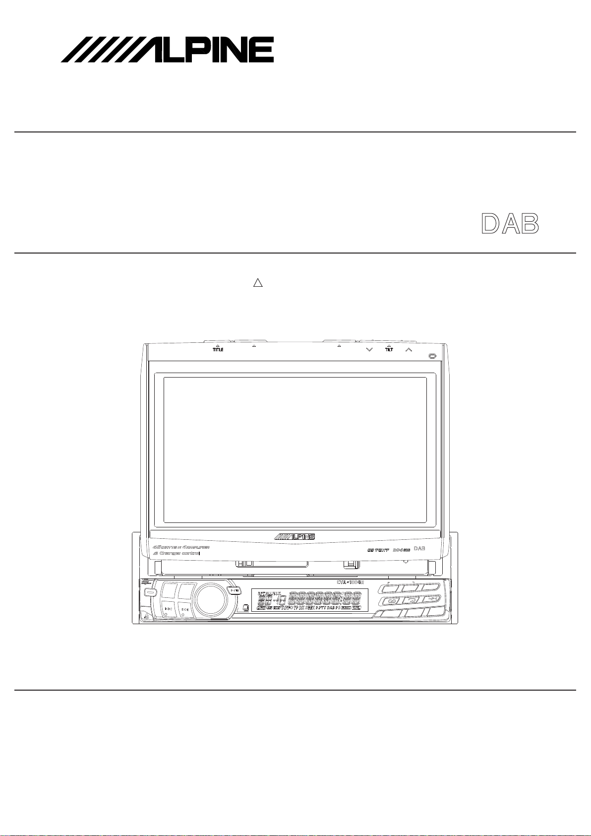
CVA-1004R
SERVICE MANUAL
MOBILE MULTIMEDIA STATION
3 / 03-A
68E35501S01
OPEN/CLOSE SLIDE
MUTE/SETUP
SOURCE
BAND
PWR
TEL.
TUNE/A.ME
MOBILE MULTIMEDIA STATION 45Wx4
MODE
FUNC
V
.SEL
T.INFO
ANNC.
3
P
.PTY
2
PTY
1
AF
4
5
6
FOLDER/CA
T
CONTROL
CONTROL
Caution : The part marked with ! is generating a high Voltage, so care will be
necessary when working.
(CVA-1004R)
/CVA-1004RR
TO ALPINE
Home Page
Page 2
<Cautions for Safe Repair Work>
r
s
The following cautions will prevent accidents in the workplace and will ensure safe products.
*The symbols indicate caution is needed to prevent injuries and damage to property.
The symbols and their meanings follow.
Warning
Caution
*The following symbols indicate two levels of cautions.
When you see this symbol, you have to be very careful.
When you see this symbol, you have to follow the instructions there.
If you ignore this symbol and handle the product incorrectly or unsafely,
serious injury or death may result.
If you ignore this symbol and handle the product incorrectly or unsafely,
injury or only material damage may result.
Warning
Do not look squarely into the laser light
coming from the pickup. Always use a designated fuse.
You may loose you sight. Use of an incorrect fuse may result in a fire.
Caution
Do not allow wiring to be caught in the Battery Caution
screw/chassis. Use the designated battery.
If wiring is caught in the screw/chassis, it may Confirm the correct polarity and seat of the
cause a short circuit, resulting in a fire. battery.
Fuse Caution
An incorrect battery or an improperly connected
or seated battery may result in a fire.
High Temperature Caution Designated Parts Caution
Touching the heat sink may cause severe burns. Look up the part list and ensure that only
designated parts are used to prevent problems or
accidents.
Reverse Power Supply Connections o
Misconnections Caution Ensure that the wiring is correct when rewiring to
Reverse power supply connections or prevent problems with ignition/breakdown.
misconnections may cause ignition problems and
smoke may result.
Soldering Caution Wear Glove
Hot solder from solder splash may cause severe Wear gloves to prevent electrical shocks or injury
burns. from the end face of the metal.
Wiring Caution
Page 3

Contents
Cabinet Assembly Parts List
Electrical Parts List
Packing Assembly Parts List
Packing Method View
System Connections
Specifications
Extension Cable
Specification Explanation
Adjustment Procedures
How to use JIG for the LPS Adjustment
Block Diagram
Parts Layout on P.W.Boards and Wiring Diagram
Schematic Diagram
Terminal Voltage of IC/TR
Description of IC Terminal
Exploded View (Cabinet)
Attention in Assembling
NOTE : Due to continuing product improvement, specifications and designs are subject to
change without notice.
Page 4
L
107
102
105
104
108
101
106
109
103
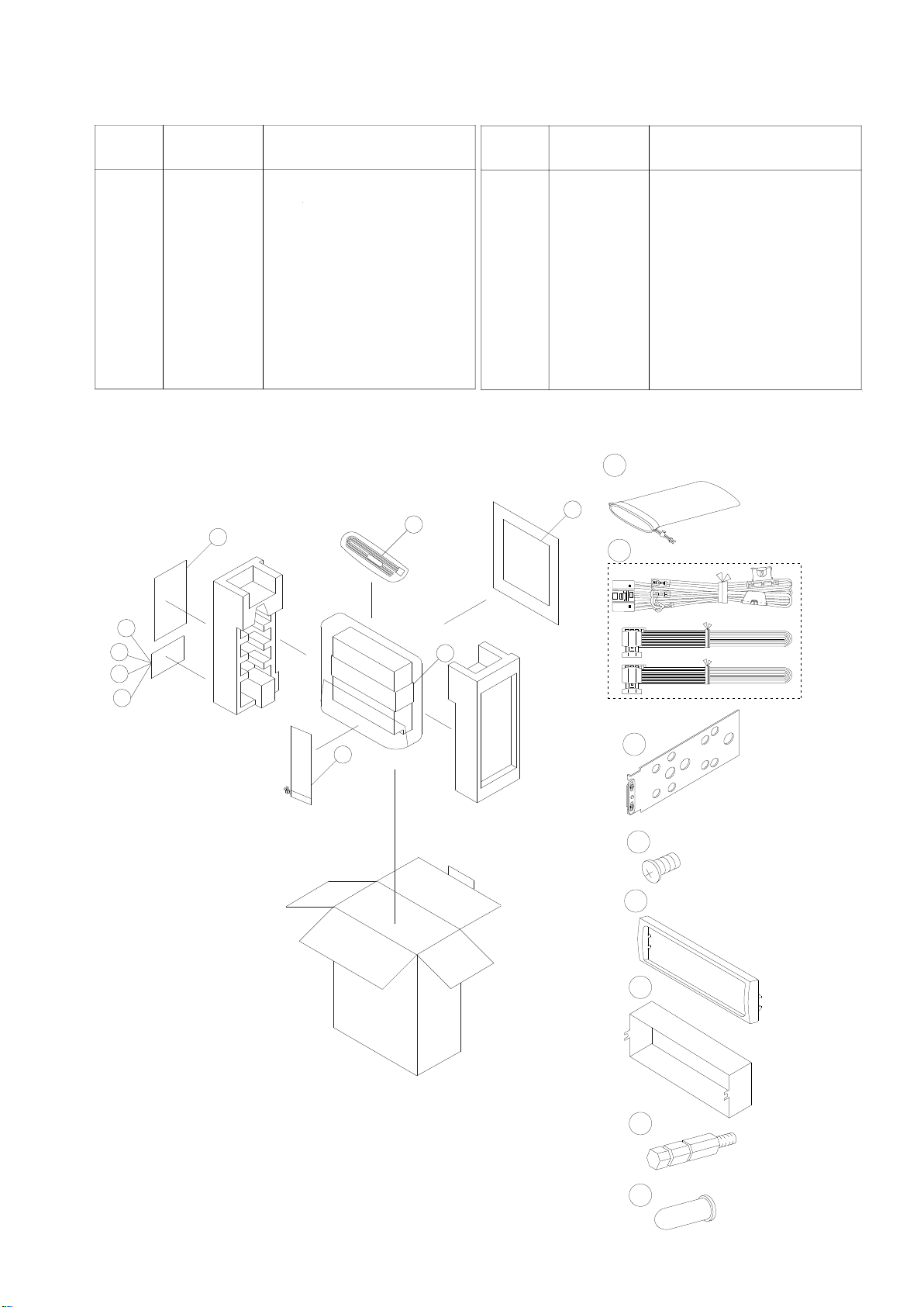
Packing Method View
X6
104
106
108
109
X1
X1
X1
105
X1
101
X1
X1
102
0.5
0.85
AMP
0.5
0.85
AMP
103
X2
Symbol
No.
Part No.
Description
Packing Assembly Parts List
Symbol
No.
Part No.
Description
101
102
103
104
105
106
107
108
109
15B03202K01
01E35519S01
07B03203K01
03A31982Y01
33C03201K01
15D03200K01
68P02294K66
03E27739S01
75E28553S01
CARRING,BAG
ASS'Y WIRE PWR
BKT,STOPPER ASS'Y
SCR M4X5 FLAT
FACE,PLATE
CASE,INNER
OWNERS MANUAL(RO/RR)
BOLT HEX M5(A)
CAP RUBBER
TO CONTENTS
Page 5
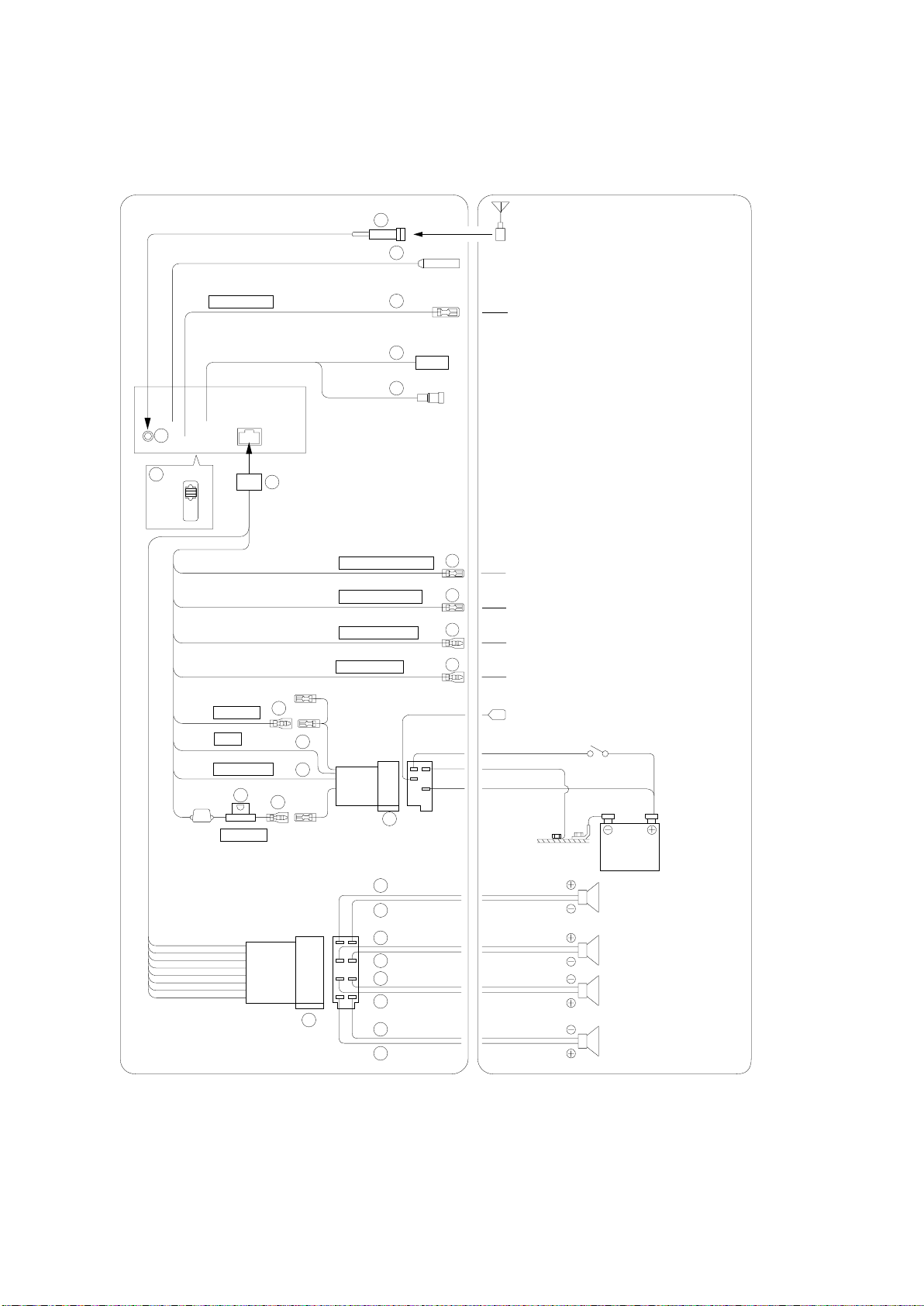
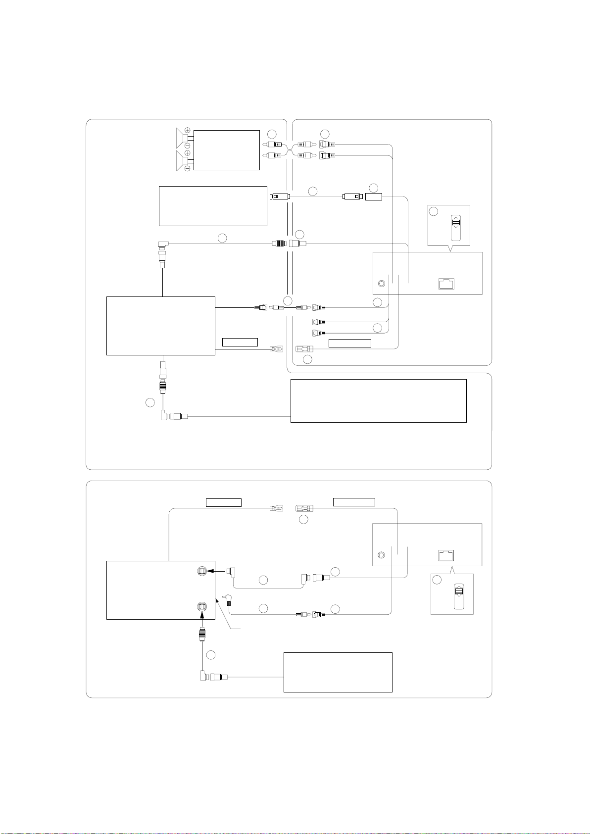
System Connections
TO CONTENTS
<Basic Connections>
2
27
NORM
EQ/DIV
(Red)
(Black)
(Blue)
Choke
Coil
(Yellow)
REMOTE OUT
(White/Brown)
IGNITION
GND
POWER ANT
11
BATTERY
17
(Pink/Black)
(Blue/White)
(Yellow/Blue)
(Orange)
7
10
8
9
1
13
14
15
16
AUDIO INTERRUPT IN
REMOTE TURN-ON
PARKING BRAKE
ILLUMINATION
12
Antenna
ISO Antenna Plug
To remote input lead
3
To vehicle phone
4
To amplifier or equalizer
5
To the parking brake signal lead
6
To the instrument cluster illumination
lead
To power antenna
Ignition
key
Battery
26
18
19
20
21
22
23
24
25
(Green)
(Green/Black)
(White)
(White/Black)
(Grey/Black)
(Grey)
(Violet/Black)
(Violet)
Rear Left
Front Left
Front Right
Rear Right
Speakers
Page 6

1 ISO Antenna Conver ter Plug
TO CONTENTS
2
Antenna Receptacle
3 Audio Interrupt In Lead (Pink/Black)
Connect this lead to the Audio Interface output of a
cellular phone which provides ground shorting when a
call is received.
If a device having the interrupt feature is connected,
audio will be automatically muted whenever the
interrupt signal is received from the device.
4
Remote Turn-On Lead (Blue/White)
Connect this lead to the remote turn-on lead of your
amplifier or signal processor.
5
Parking Brak
e Lead (Y
ellow/Blue)
Connect this lead to the power supply side of the
parking brake switch to transmit the parking brake
status signals to the CVA-1004R/CVA-1004RR.
6
Illumination Lead (Orange)
This lead may be connected to the vehicle's instrument
cluster illumination lead. This will allow the
backlighting of the CVA-1004R/CVA-1004RR to dim
whenever the vehicle's lights are turned on.
7 Switched Power Lead (Ignition) (Red)
Connect this lead to an open terminal on the vehicle's
fuse box or another unused power source which
provides (+) 12V only when the ignition is turned on
or in the accessory position.
8 Ground Lead (Black)
Connect this lead to a good chassis ground on the
vehicle. Make sure the connection is made to bare
metal and is securely fastened using the sheet metal
screw provided.
9 Power Antenna Lead (Blue)
Connect this lead to the +B terminal of your power
antenna, if applicable.
NOTE
This lead should be used only for controlling the
vehicle's power antenna. Do not use this lead to turn on
an amplifier or a signal processor, etc.
Battery Lead (Yellow)
10
Connect this lead to the positive (+) post of the
vehicle's battery.
11
Fuse Holder (15A)
12
ISO Power Supply Connector
13
Remote Control Interface Connector
To remote control interface box.
14
Remote Control Output Lead (White/Brown)
Connect this lead to the remote control input lead.
This lead outputs the controlling signals from the
remote control.
15
RGB Input Connector
16
Ai-NET Cable
17
Power Supply Connector
18
Left Rear (+) Speaker Output Lead (Green)
Left Rear (–) Speaker Output Lead (Green/
19
Black)
20
Left Front (+) Speaker Output Lead (White)
21
Left Front (–) Speaker Output Lead (White/Black)
Right Front (–) Speaker Output Lead (Grey/
22
Black)
23
Right Front (+) Speaker Output Lead (Grey)
24
Right Rear (–) Speaker Output Lead (Violet/
Black)
25
Right Rear (+) Speaker Output Lead (Violet)
26
ISO Connector (Speaker Output)
27
System Switch
When connecting an equalizer or divider using AiNET feature, place this switch in the EQ/DIV
position. When no device is connected, leave the
switch in the NORM position.
NOTE
Be sure turn the power off to the unit before changing the
switch position.
Page 7
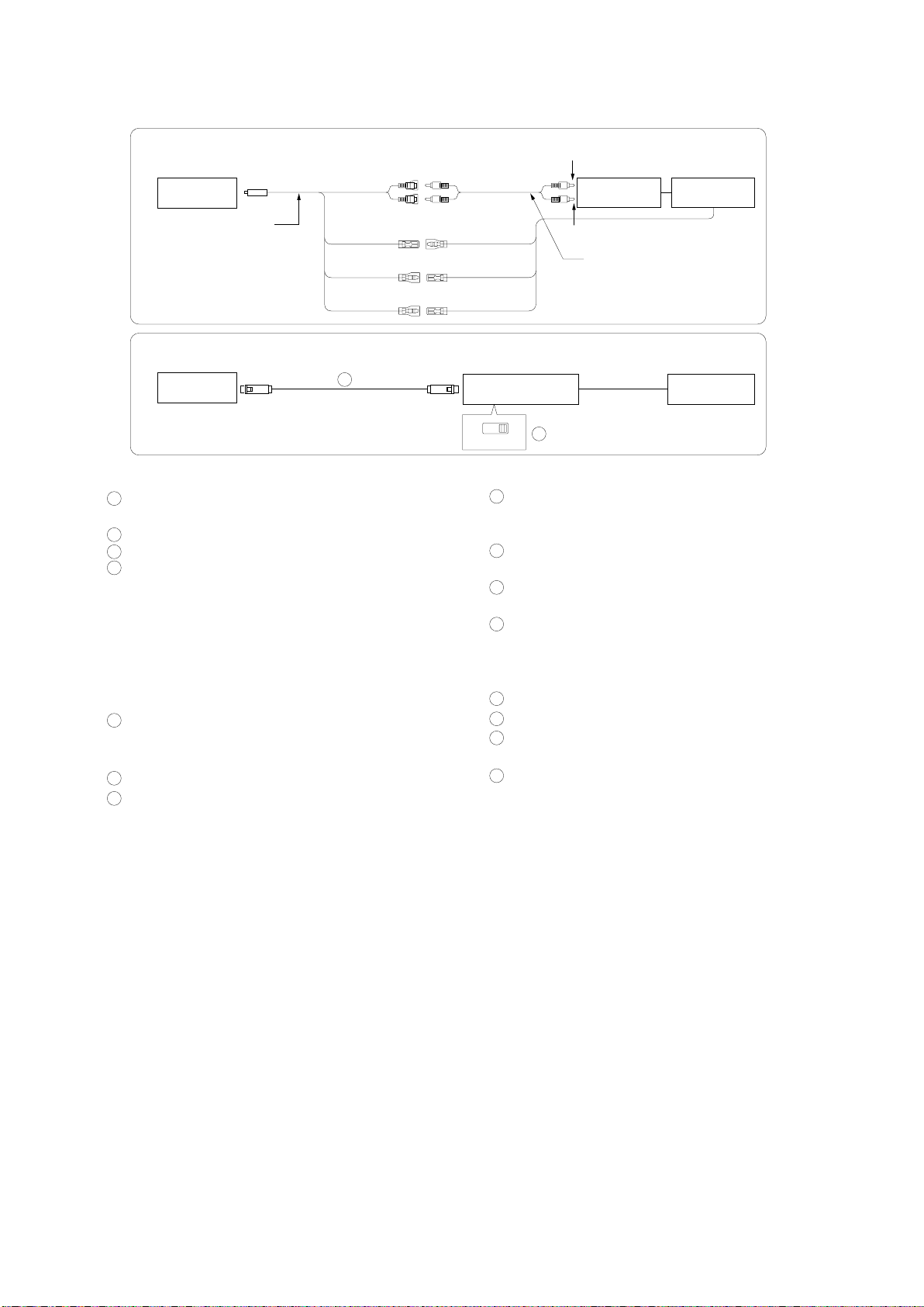
<System Example 1: Refer also to Basic Connections.>
TO CONTENTS
Speakers
Rear or
Subwoofer
(NVE-N077P)
DVD Video Player
(Sold Separately)
12
Amplifier
Navigation System
(Sold Separately)
6
REMOTE IN
(White/Brown)
(Yellow)
2
1
3
7
4
NORM
5
9
11
(Yellow)
(White)
(Red)
REMOTE OUT
(White/Brown)
8
10
EQ/DIV
CD Changer (Ai-NET)
(Sold Separately)
* When Subwoofer is set to OFF: Output is from Rear speakers.
When Subwoofer is set to ON: Output is from Subwoofer.
When connecting the DVD changer
REMOTE IN
(White/Brown)
11
DVD Changer
13
(Sold Separately)
14
To VIDEO OUT terminal
(Yellow)
12
CD Changer
(Sold Separately)
REMOTE OUT
(White/Brown)
5
8
4
NORM
EQ/DIV
Page 8
When connecting with NVE-N055PS of the Alpine's Navigation System
TO CONTENTS
CVA-1004R/
VIDEO IN
CVA-1004RR
RGB Converter Cable
KCE-030N (Sold Separately)
REMOTE OUT
(White/Brown)
DISP CONT IN
(Yellow/Red)
GUIDE CONT IN
(White/Green)
GUIDE IN
REMOTE IN
(White/Brown)
DISP CONT OUT
(Yellow/Red)
GUIDE CONT OUT
(White/Green)
When connecting with NVE-N055PV of the Alpine's Navigation System
CVA-1004R/
CVA-1004RR
3
Connector Box Navigation
To Video output terminal
(NVE-N055PS)
Connector Box
Navigation
To Guide output terminal
RCA Extension Cable
(Included with Navigation)
(NVE-N055PV)
1
Rear/Subwoofer Output RCA Connectors
RED is right and WHITE is left.
2 RCA Extension Cable (Sold Separately)
3 RGB Cable (Included with Navigation)
4
System Switch
When connecting an equalizer or divider using AiNET feature, place this switch in the EQ/DIV
position. When no device is connected, leave the
switch in the NORM position.
NOTE
Be sure turn the power off to the unit before changing the
switch position.
5
Ai-NET Connector
Connect this to the output or input connector of other
product equipped with Ai-NET.
6 Ai-NET Cable (Included with DVD video player)
7 RGB Input Connector
Connect to the RGB output terminal of the navigation
system.
NTSC RGB
15
8 AUX Video Input (AUX1) Connector
Connect the video output lead of a DVD video player
or DVD changer to this terminal.
9 RCA Extension Cable (Included with DVD Video
Player)
10
AUX Audio Input (AUX1) Connectors
(not used for this system)
11
Remote Control Output Lead (White/Brown)
Connect this lead to the remote control input lead.
This lead outputs the controlling signals from the
remote control.
12
Ai-NET Cable (Included with CD Changer)
13
Ai-NET Cable (Included with DVD Changer)
14
RCA Extension Cable (Included with DVD
Changer)
15
RGB/NTSC Output Switch
To display the picture of Navigation system on the
external monitor, place the switch in the NTSC Output
position.
Page 9
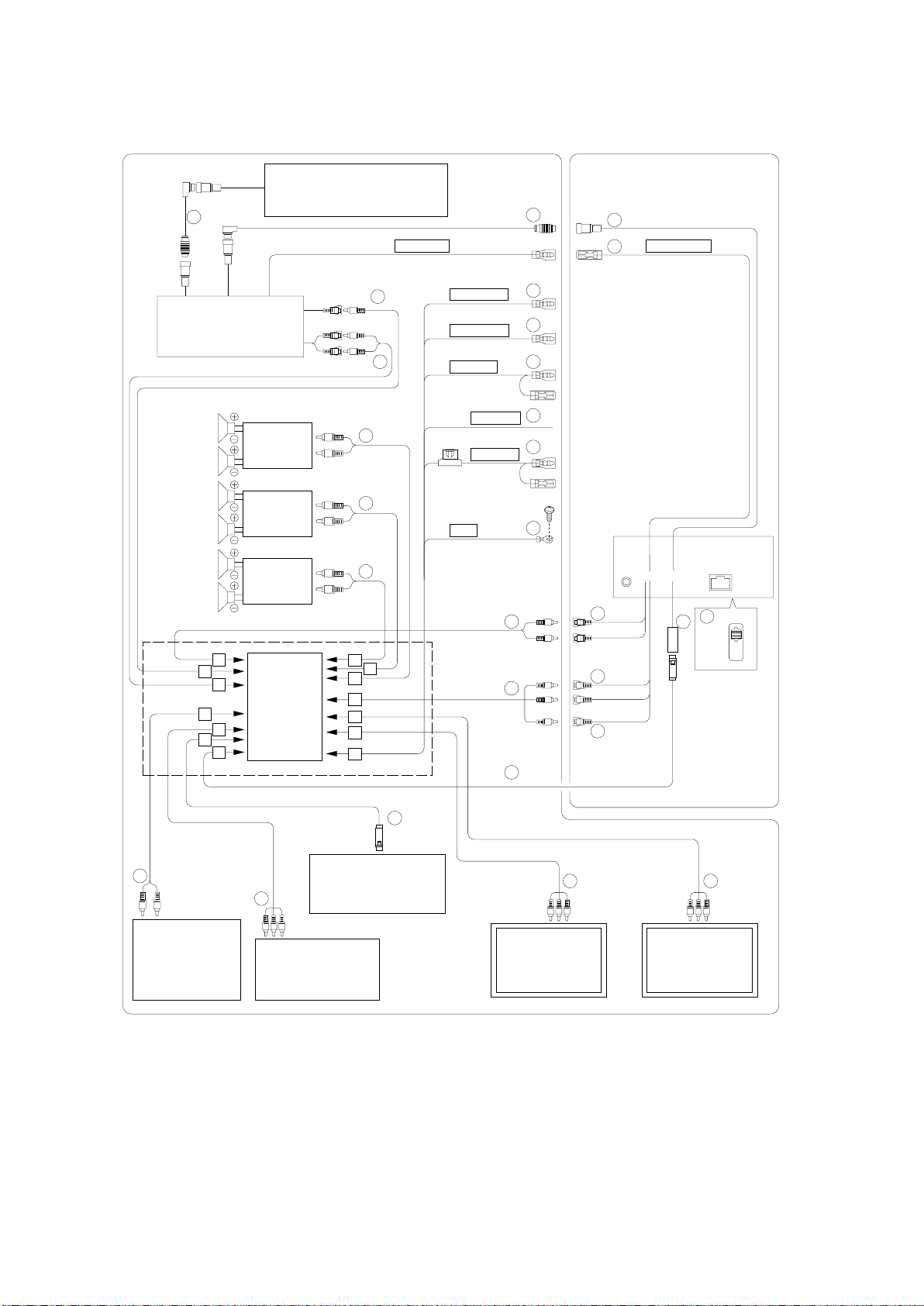
<System Example 2 (connecting to the optional KCE-104V):
TO CONTENTS
Refer also to Basic Connections.>
CD Changer (Ai-NET)
(Sold Separately)
4
REMOTE IN
(White/Brown)
3
1
2
REMOTE OUT
(White/Brown)
DVD Video Player
(Sold Separately)
(DVA-5205/DHA-S680 series)
Speakers
Subwoofers
Amplifier
Rear Left
Amplifier
Rear Right
Front Left
Amplifier
Front Right
A
B
C
E
F
(KCE-104V)
D
G
(Yellow)
(White: L-ch)
(Red: R-ch)
17
18
18
18
18
N
M
L
REAR SEL 1
(Grey/Pink)
REAR SEL 2
(Black/Pink)
IGNITION
(Red)
REVERSE
(Orange/White)
BATTERY
(Yellow)
GND
(Black)
K
J
I
5
6
7
8
To vehicle's reversing lamp
9
10
19
19
14
15
(Red)
(White)
(Yellow)
16
13
12
NORM
EQ/DIV
*1
H
31
33
TV Tuner
(Sold Separately)
(TUE-T152)
NOTE : *1
32
Navigation System
18
(Sold Separately)
(NVE-N077P)
Rear Monitor
Rear Camera
(Sold Separately)
(Sold Separately)
(TME-M760)
Be sure turn the power off to the unit before changing the
18
switch position.
18
Rear Monitor
(Sold Separately)
(TME-M760)
Page 10
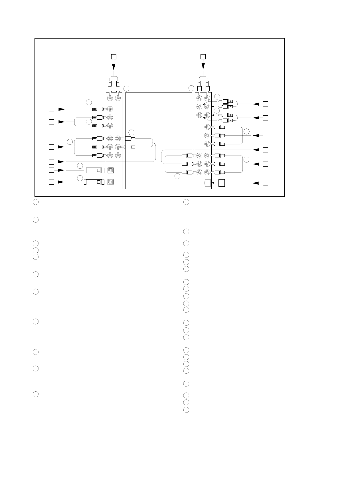
Detail of the expansion box KCE-104V (sold separately)
TO CONTENTS
A
(Red)
(White)
25
26
28
(Yellow)
(White)
(Red)
(Yellow)
(White)
(Red)
29
30
26
27
(Yellow)
(Black)
B
C
D
E
F
G
1 Ai-NET Connector
Connect this to the output or input connector of other
product equipped with Ai-NET.
2 Remote Control Output Lead (White/Brown)
Connect this lead to the remote control input lead. This
lead outputs the controlling signals from the remote
control.
3 Ai-NET Cable (Included with DVD video player)
4 Ai-NET Cable (Included with CD Changer)
5 Rear Select 1 Lead (Grey/Pink)
Connect this lead to the ground lead with a push switch,
etc.
6 Rear Select 2 Lead (Black/Pink)
Connect this lead to the ground lead with a push switch,
etc.
7 Switched Power Lead (Ignition) (Red)
Connect this lead to an open terminal on the vehicle's fuse
box or another unused power source which provides (+)
12V only when the ignition is turned on or in the accessory
position.
8 Reverse Lamp Signal Input Lead (Or
ange/White)
Used to automatically switch to the rear camera input.
Connect this lead to the positive side of the vehicle's
reverse lamp. The video input will automatically switch to
the rear camera whenever the vehicle is backing up.
9 Battery Lead (Yellow)
Connect this lead to the positive (+) post of the vehicle's
battery.
10
Ground Lead (Black)
Connect this lead to a good chassis ground on the vehicle.
Make sure the connection is made to bare metal and is
securely fastened using the sheet metal screw provided.
11
Fuse Holder (7.5A)
(Red)
(White)
(Yellow)
23
N
(White)
(Red)
20
20
21
(Red)
(White)
(Yellow)
(Red)
(White)
(Yellow)
(White)
(Red)
(Red)
(White)
22
24
M
L
K
J
I
H
12
System Switch
When connecting an equalizer or divider using Ai-NET
feature, place this switch in the EQ/DIV position. When no
device is connected, leave the switch in the NORM
position.
13
RGB Input Connector
Connect to the RGB output terminal of the KCE-104V.
14
Rear/Subw
er Output RCA Connectors
oof
RED is right and WHITE is left.
15
AUX Audio Input (AUX1) Connectors
16
AUX Video Input (AUX1) Connector
RCA Extension Cable (Included with DVD video
17
player)
18
RCA Extension Cable (Sold Separately)
19
RCA Extension Cable (Included with the KCE-104V)
20
To Front/Rear PREOUT Terminals of the KCE-104V
To Subwoofer Terminals of the KCE-104V
21
22
Connect to the AUX Input (AUX1) Connectors of the
CVA-1004R/CVA-1004RR
23
To A
UX1 Output
24
To A
UX2 Output
25
To Sound Input Terminals of the KCE-104V (from the
Terminals of the KCE-104V
Terminals of the KCE-104V
CVA-1004R/CVA-1004RR)
To A
26
27
28
29
UX Input1
To A
UX Input2
UX Input3
To A
Connect to the RGB Terminal of the Navigation
Terminals of the KCE-104V
Terminals of the KCE-104V
Terminals of the KCE-104V
System
30
Connect to the RGB Input
Terminal of the CVA-1004R
/CVA-1004RR
31
RGB Cable (Included with the KCE-104V)
32
RGB Cable (Included with Navigation System)
33
RCA Extension Cable (Included with the TUE-T152)
Page 11

Specifications
<Monitor SECTION>
Screen Size .................................................................................................................................................... 6.5-type
Display System ................................................................................................................... Transparent type TN LCD
Drive System ................................................................................................................................... TFT active matrix
Number of Picture Elements ............................................................................................ 280,800 pcs. (1,200 x 234)
Light Source ................................................................................................. U-shaped cold cathode fluorescent tube
<Tuner SECTION - FM RADIO>
Intermediate Frequency ......................................................................................................................... 10.7±0.1MHz
Frequency Range ............................................................................................................................... 87.5 to 108MHz
Usable Sensitivity (Mono, 30dB S/N, at 98.1MHz) .......................................................................................... 20.2dBf
-3dB Limiting Sensitivity (at 98.1MHz) ............................................................................................................ 21.2dBf
Residual Noise (Ref. 400Hz, at 98.1MHz) .................................................................................................... 28±10dB
S/N Ratio (at 98.1MHz) ......................................................................................................................... Stereo : 55dB
Mono : 58dB
Image Rejection (at 106.1MHz) .......................................................................................................................... 40dB
IF Rejection (at 90.1MHz) ................................................................................................................................... 60dB
Distortion (Input 60dBu, at 98.1MHz) ..................................................................................................................... 1%
Frequency Response (Ref. 400Hz, at 98.1MHz) ................................................................................. 100Hz : 0±3dB
10kHz : -10±3dB
Stereo Separation (1kHz, at 98.1MHz) ............................................................................................................... 20dB
PS Sensitivity (at 98.1MHz) ............................................................................................................................ 36.2dBf
<Tuner SECTION - MW RADIO>
Intermediate Frequency ....................................................................................................................... 1st. : 10.7MHz
2nd. : 450kHz
Frequency Range .............................................................................................................................. 531 to 1,602kHz
Usable Sensitivity (20dB S/N, at 999kHz) ........................................................................................................... 36dB
S/N Ratio (at 999kHz) ......................................................................................................................................... 44dB
Image Rejection (at 1,404kHz, 2nd. IF) .............................................................................................................. 50dB
IF Rejection (at 603kHz, 2nd. IF) ........................................................................................................................ 60dB
Distortion (at 999kHz) .......................................................................................................................................... 1.5%
Frequency Response (Ref. 400Hz, at 999kHz) .................................................................................. 100Hz : -3±4dB
2.5kHz : -3±4dB
<Tuner SECTION - LW RADIO>
Intermediate Frequency ....................................................................................................................... 1st. : 10.7MHz
2nd. : 450kHz
Frequency Range ................................................................................................................................. 153 to 281kHz
Usable Sensitivity (20dB S/N, at 216kHz) ........................................................................................................... 42dB
S/N Ratio (at 216kHz) ......................................................................................................................................... 44dB
Image Rejection (at 270kHz, 2nd. IF) ................................................................................................................. 50dB
IF Rejection (at 162kHz, 2nd. IF) ........................................................................................................................ 60dB
Distortion (at 216kHz) .......................................................................................................................................... 1.5%
Frequency Response (Ref. 400Hz, at 216kHz) .................................................................................. 100Hz : -3±4dB
2.5kHz : -3±4dB
TO CONTENTS
Page 12

<GENERAL>
TO CONTENTS
Signal System .......................................................................................................................................... PAL System
Power Supply ............................................................................................................. DC14.4V (11 to 16V allowable)
Power Output (Ref. CD 1kHz, 0dB (TCD-782, No.2), T.H.D. 10%) /Impedance ................................... 18W/ch/4ohm
Pre Output (Ref. CD 1kHz, 0dB (TCD-782, No.2), T.H.D. 1%) /Impedance .............. REAR : 2V±2.5dBV/ch/10kohm
Back-up Current (ACC OFF 30Sec. After) ........................................................................................................... 5mA
Dimensions (W x H x D) ................................................................................................. Chassis : 178 x 50 x 165mm
Nose (Closed) : 170 x 46.2 x 28.5mm
Nose (Maximum Projected Position) : 170 x 46.2 x 153mm
Weight ................................................................................................................................................................. 2.1kg
NOTE : Due to Continuing product improvement, specifications and designs are subject to change without notice.
Page 13
Extension Cable
TO CONTENTS
* When repairing or measuring the voltage of this unit, connect with the Extension Cable as shown in below.
TUNER P.W.Board
MAIN P.W.Board
01V28083S01
FRONT P.W.Board
Page 14

Specification Explanation
TO CONTENTS
1. Cancellation of AUX Regulation (Parking Wire)
(1) HAND : L
2. Soft Version (Check Sum)
Push "SOURCE/PWR" Key and "F5" Key at the same time.
3. Elimination of EEP-ROM Memory
After pushing "SOURCE/PWR" Key and "CHG/R.SEL" Key at the same time, push "PLAY/PAUSE/TUNE/A.ME" more
than 3 seconds, and confirm by ACC OFF/ON.
Page 15
Adjustment Procedures
45ohm
10ohm
60ohm
Input
Output
For 50 ohm FM Signal Generator
Figure 1
FM Signal Generator
FM Dummy
Antenna
Antenna Receptacle
+
-
+
-
CVA-1004R/
CVA-1004RR
Figure 2
TP504
GND
TP502
DC Volt Meter
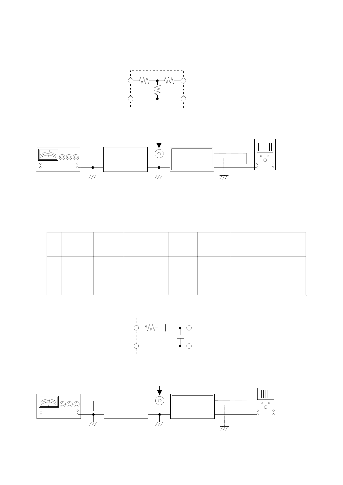
-1. FM SECTION
1. TUNER Adjustment
(1) Dummy Antenna Circuit
(2) Connection
Step
Description
Connection
Signal Generator
Dial Control
Test Point /
P.W.Board
Coordinates
Adjustment
1FMAdjustment
Figure 2
87.5MHz, 26dBuV
(Mod. OFF, MONO,
40KHz(53.8%),
Pilot(19KHz) :
6.0KHz(8%))
87.5MHz
TP502
(4-A)
TP504
(4-A)
Auto Adjustment : After setting up of
Signal Genarator, short GND and
TP502.
(SPEC) TP504 : 1.5±0.05V
For 50 ohm AM Signal Generator
15pF
30ohm
65pF
Input
Output
Figure 3
AM Dummy
Antenna
Antenna Receptacle
+
-
+
-
CVA-1004R/
CVA-1004RR
Figure 4
* only short-circuit at adjustment
TP504
GND
TP502
DC Volt Meter
-2. MW/LW SECTION
(1) Dummy Antenna Circuit
(2) Connection
TO CONTENTS
(3) Control Settings
Fader Control ...................................... Center Position Bass Control .................................. Center Position
Balance Control
Treble Control ..................................... Center Position Others .............................................................. OFF
................................... Center Position Band Switch ...................................................... FM
(4) Adjustment Procedores
Page 16
(3) Control Settings
Fader Control ...................................... Center Position Bass Control .................................. Center Position
Balance Control ................................... Center Position Band Switch ............................................... MW/LW
Treble Control ..................................... Center Position Others .............................................................. OFF
(4) Adjustment Procedores
Step
Description
Connection
Signal Generator
Dial Control
Test Point /
P.W.Board
Coordinates
Adjustment
1MWAdjustment
Figure 4
999KHz, 33dBuV
(Mod. OFF,
MONO, 30%)
999KHz
TP502
(4-A)
TP504
(4-A)
Auto Adjustment : After setting up of
Signal Genarator, short GND and
TP502.
(SPEC) TP504 : 1.0±0.05V
2LWAdjustment
Figure 4
216KHz, 33dBuV
(Mod. OFF,
MONO, 30%)
216KHz
TP502
(4-A)
TP504
(4-A)
Auto Adjustment : After setting up of
Signal Genarator, short GND and
TP502.
(SPEC) TP504 : 1.0±0.05V
TO CONTENTS
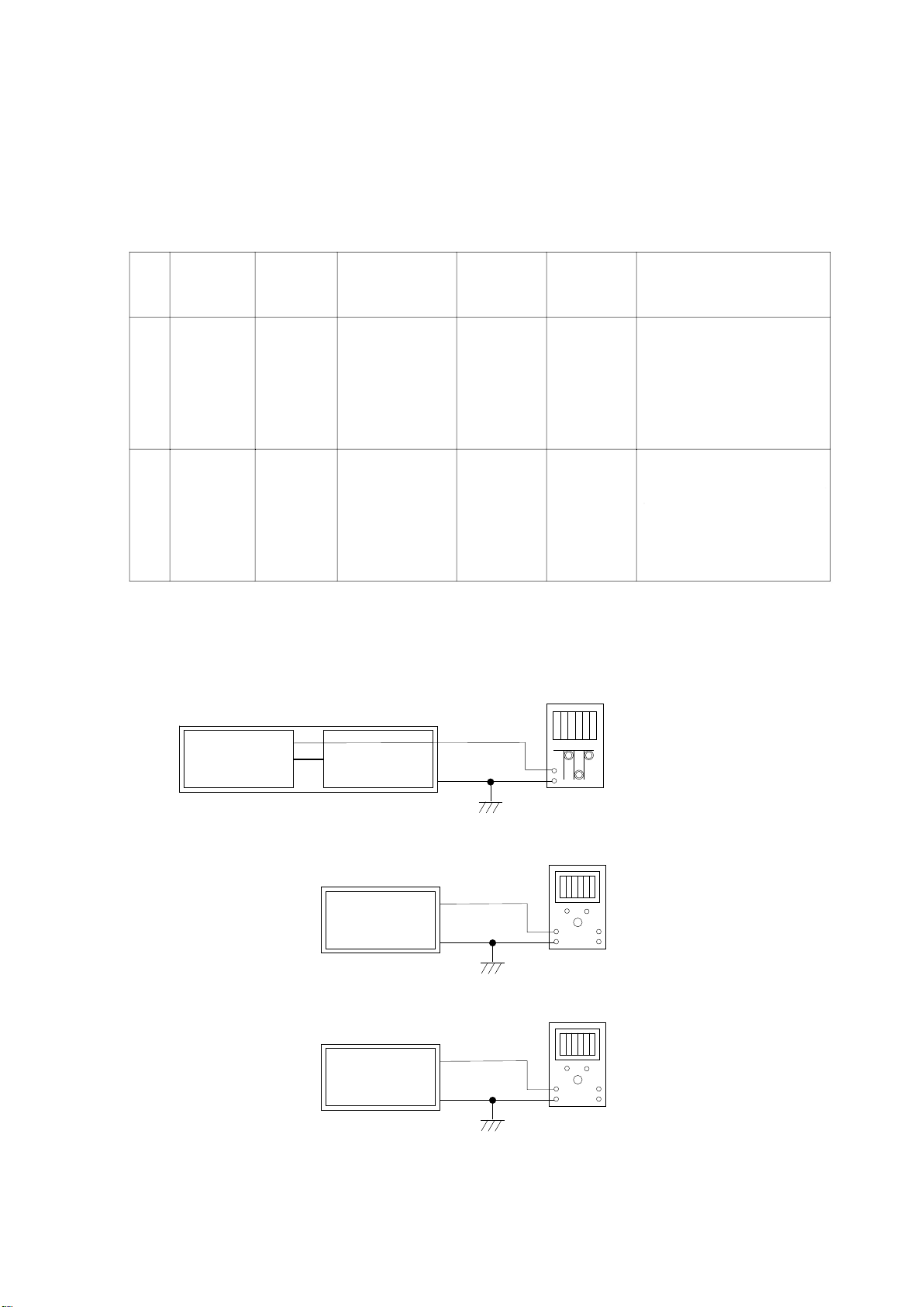
2. VIDEO Adjustment
(1) Connection
MAIN P.W.Board
CVA-1004R/
CVA-1004RR
TP813
VGND(TP7050)
LCD P.W.Board
CVA-1004R/
CVA-1004RR
TP7053
VGND(TP7050)
LCD P.W.Board
CVA-1004R/
CVA-1004RR
TP7002
VGND(TP7050)
LCD P.W.Board
Frequency Counter
+
-
Figure 5
DC Volt Meter
+
-
Figure 6
DC Volt Meter
+
-
Figure 7
Page 17
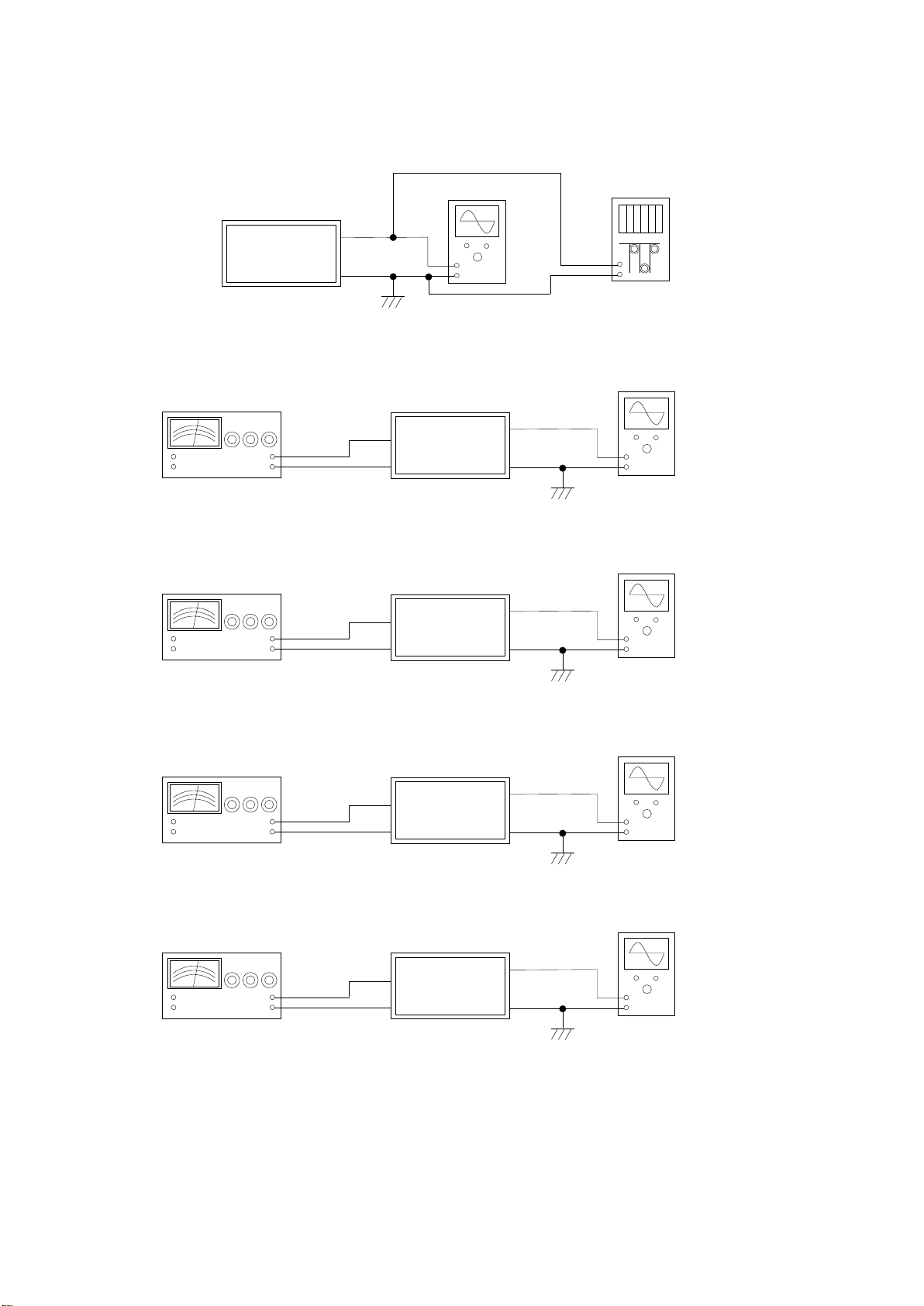
Pattern Generator
+
-
+
-
CVA-1004R/
CVA-1004RR
Figure 9
TP7056
AUX IN
VGND
(TP7050)GND
Oscilloscope
LCD P.W.Board
Pattern Generator
+
-
+
-
CVA-1004R/
CVA-1004RR
Figure 10
TP7015
AUX IN
GND
Oscilloscope
LCD P.W.Board
Pattern Generator
+
-
+
-
CVA-1004R/
CVA-1004RR
Figure 11
TP7014
AUX IN
GND
Oscilloscope
LCD P.W.Board
Pattern Generator
+
-
+
-
CVA-1004R/
CVA-1004RR
Figure 12
TP7016
AUX IN
GND
Oscilloscope
LCD P.W.Board
CVA-1004R/
CVA-1004RR
VGND
(TP7050)
VGND
(TP7050)
VGND
(TP7050)
+
-
Figure 8
TP7046
Oscilloscope
LCD P.W.Board
VGND(TP7050)
+
-
Frequency Counter
(10STEP Signal)
(10STEP Signal)
(10STEP Signal)
(10STEP Signal)
TO CONTENTS
Page 18

(2) Adjustment Procedures
TO CONTENTS
* PAL Adjustment
Step Operations Process Connection
1 Confirm AUX terminal OPEN. Figure 5 to 8
2 PWM Frequency Adjustment Figure 5
3 VSS Voltage Adjustment Figure 6
4 VGH Voltage Adjustment Figure 7
HSYNC Frequency
5
Adjustment
6 HSYNC Lo-period Adjustment Figure 8
Input 10STEP Signal from
7
AUX.
8 VOM Amplitude Adjustment Figure 9
GREEN Waveform-1
9
Adjustment
GREEN Waveform-2
10
Adjustment
GREEN Waveform-3
11
Adjustment
12 RED Waveform-1 Adjustment Figure 11
13 BLUE Waveform-1 Adjustment Figure 12
Figure 8
Figure 9 to 12
Figure 10
Figure 10
Figure 10
Test Point/
P.W.Board
Coordinates
TP813
(4-F)
TP7050
(5-C)
TP7053
(5-C)
TP7050
(5-C)
TP7002
(5-C)
TP7050
(5-C)
TP7046
(5-C)
TP7050
(5-C)
TP7046
(5-C)
TP7050
(5-C)
TP7056
(5-C)
TP7050
(5-C)
TP7015
(5-C)
TP7050
(5-C)
TP7015
(5-C)
TP7050
(5-C)
TP7015
(5-C)
TP7050
(5-C)
TP7014
(5-C)
TP7050
(5-C)
TP7016
(5-C)
TP7050
(5-C)
Adjustment
Adjust by VR803 so that it may be set to 119 to
120KHz.
Adjust by VR802 so that it may be set to -16V
+0.1, -0.1.
Adjust by VR801 so that it may be set to +13V
+0.1, -0.1.
Adjust by VR7002 so that it may be set to
range which does not exceed 15.64kHz from
15.63KHz.
Adjust by VR7001 so that it may be set to
3.12uS+0.05, -0.05.
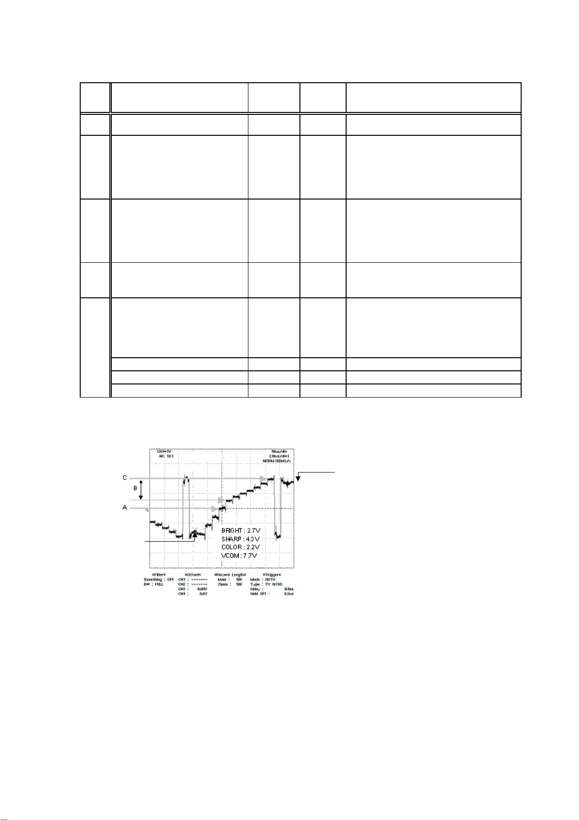
Adjust to DC+5.9 to -1.9 amplitude by VR701
and VR709. (7.8V+0.1, -0.1)
[NOTE :
VR701 : DC Center Voltage Adjustment
VR709 : Amplitude Adjustment]
Adjust from black to the 3rd. waveform by
VR702 so that it may be set to AC1.9V.
(Refer to A of Figure 13)
Adjust between white and from white to the 6th.
waveform by VR703 so that it may be set to
AC3.0V
(Refer to B of Figure 13)
Adjust white waveform by VR703 so that it may
be set to AC3.9 to 4.0V.
(Refer to C of Figure 13)
Adjust by VR705 and VR707 so that TP7014
waveform may become the same as TP7015
waveform.
[NOTE :
VR705 : adjust from black to 8th. gradation.
VR707 : adjust from 8th. gradation to white.]
Adjust by VR706 and VR708 so that TP7016
waveform may become the same as TP7015
waveform.
[NOTE :
VR706 : adjust from black to 8th. gradation.
VR708 : adjust from 8th. gradation to white.]
Page 19
Step Operations Process Connection
TO CONTENTS
After finishing PAL Adjustment,
14
change to COLOR BAR Signal.
15 RED Waveform-2 Adjustment Figure 11
Test Point/
P.W.Board
Coordinates
TP7014
(5-C)
TP7050
(5-C)
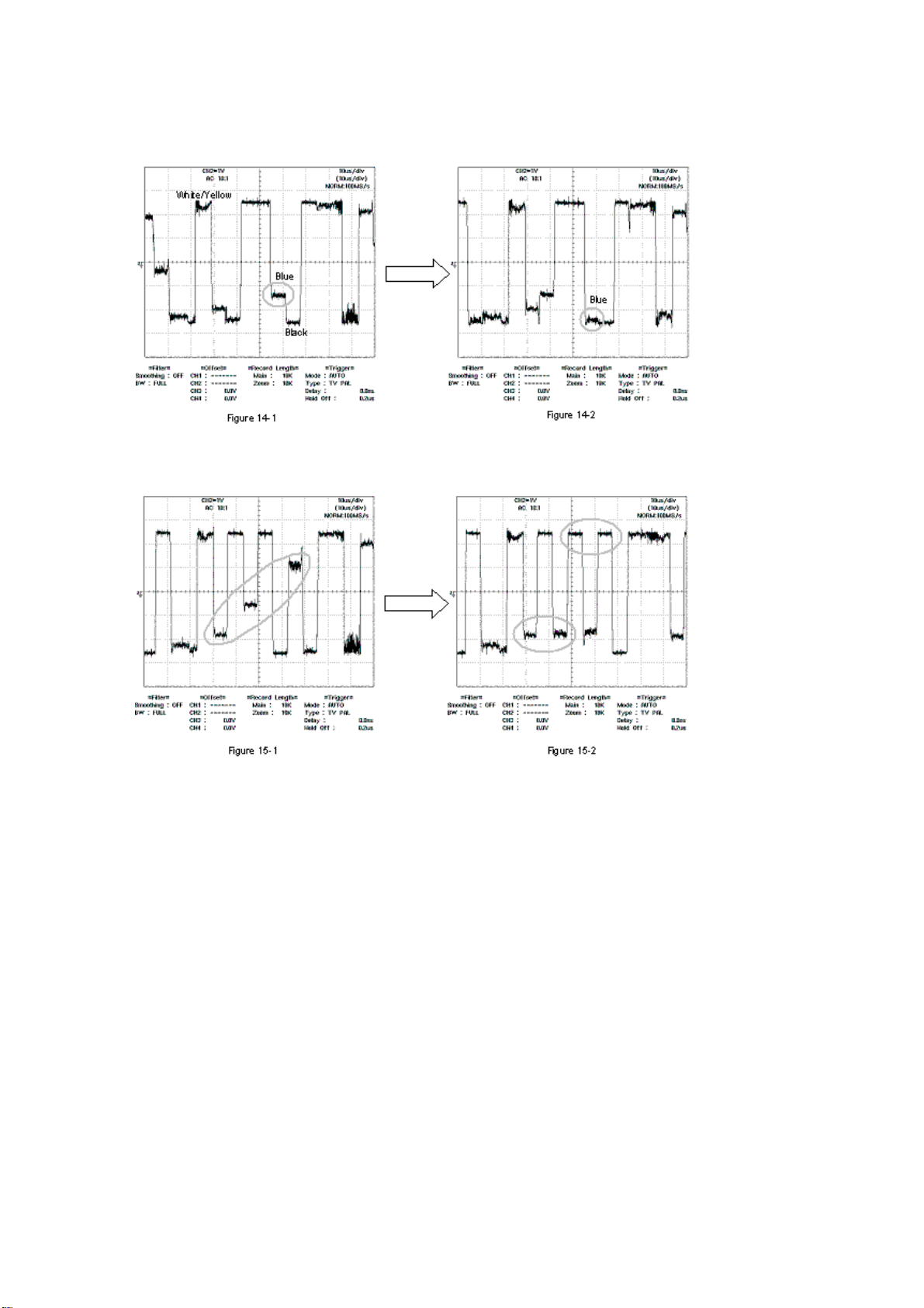
Adjustment
Adjust by L706 so that blue level of TP7014
waveform may become the same as black level
of TP7014 Waveform.
(Refer to Figure 14-1 and -2.)
NOTE : It is the easy method which is adjusted
looking at COLOR BAR reflected in LCD directly.
16 BLUE Waveform-2 Adjustment Figure 12
B.GND [DAY] is set to GREEN-2 on
17
the SETUP screen of FM SOURCE,
and flicker is adjusted.
-1. After pushing "SOURCE/PWR"
Key and "CHG/R.SEL" Key at
the same time, push "PLAY/
PAUSE/TUNE/A.ME" more than
18
3 seconds.
-2. ACC ON/FF
-3. Elimination of EEP-ROM Memory
-4. BLUE-1 screen
TP7016
(5-C)
TP7050
(5-C)
Adjust by VR710 so that the output amplitude of
every 1H may be united by TP7016 waveform.
(Refer to Figure 15-1 and -2.)
NOTE : It is adjustment standard that the flicker
of magenta and RED becomes the minimum.
White Position
Black Position
Figure 13
Page 20
<Before Adjustment>
TO CONTENTS
<After Adjustment>
<Before Adjustment>
<After Adjustment>
Page 21
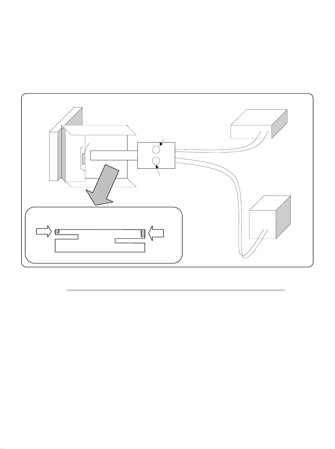
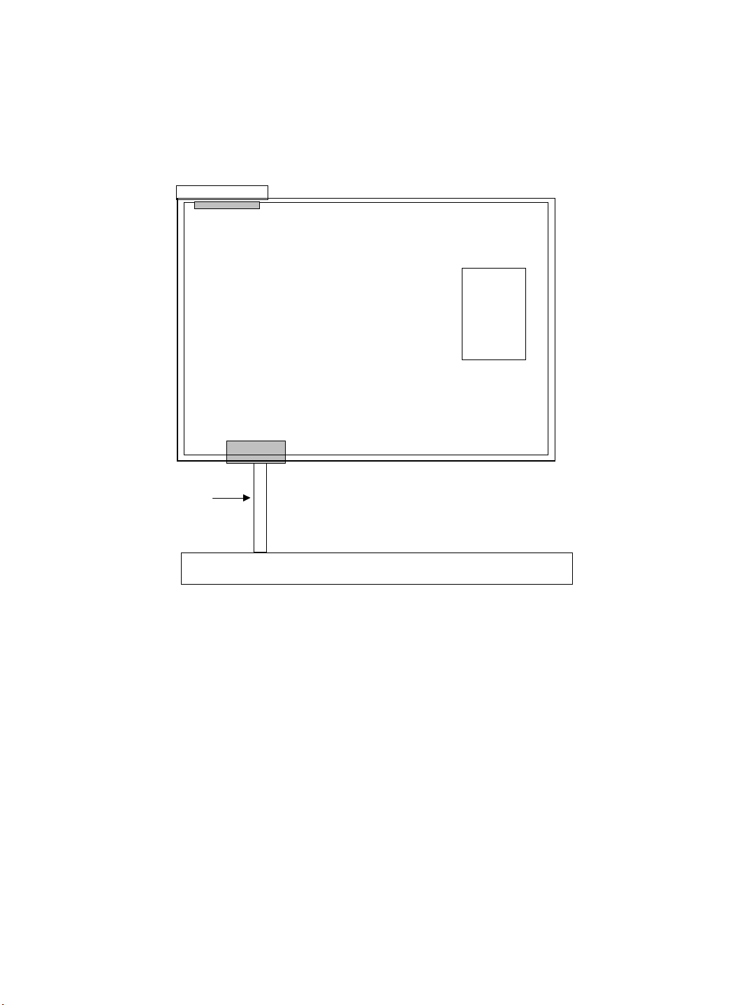
How to use jig for the LPS Adjustment (01V32359S01)
TO CONTENTS
Outline
Our JIG is JIG which makes Mechanism Block move to adjust the voltage of LPS for TILT of in-dash monitor such as
“CVA-1004RCVA-1004RR”. It is adjusted with measuring an output voltage from LPS and confirming the voltage.
(This adjustment surely becomes necessary when MONITOR and Mechanism Block are left.)
Connection Figure
Multi Meter
SW1
Red Wire
Black Wire
SW2
Power
Supply
12V input
It is inserted into
the product. (26P)
Vacancy
It is put here.
JIG FLEX.
It is inserted into
the jig. (40P)
Vacancy
How to use it (Be sure to carry out this adjustment when you leave DISPLAY and MONITOR Mechanism Block.)
1. It is connected as the above “Connection Figure”.
2. Power supply is turned on. (12V)
3. DISPLAY is moved to the horizontal position by using the switch. (Refer to Figure-1.)
1) SW1 : The adjustment of TILT is done. (angle adjustment of MONITOR Block)
2) SW2 : The adjustment of Load is done. (The dimension that MONITOR Block comes out is adjusted.)
4. COVER TURNER is removed.
5. GEAR, LPS ASSY (121) are removed.
6. Volume under GEAR, LPS ASSY is turned, and the voltage of the Multi Meter adjusts it to 0.10+0.10, -0.10V
(the voltage of MONITOR horizontal position). (Refer to Figure-2.)
7. GEAR, LPS ASSY are put after the adjustment.
It confirms that it is 0.01 to 0.20V though voltage value changes a little when it is put.
(Adjustment is necessity again if it comes off 0.01 to 0.20V.)
8. COVER TURNER is put, JIG FLEX. is removed, adjustment completion.
Page 22

Figure-1
TO CONTENTS
SW1 is pushed down on the A side,
and Display is made horizontal.
(It is made the condition like the Figure.)
It is made horizontal.
SW1
AB
SW2
The figure which saw
SW from the top
Multi Meter
Power
Supply
Figure-2
Volume under GEAR, LPS ASSY is turned, and the voltage of the Multi Meter adjusts it to 0.10+0.10, -0.10V
(the voltage of MONITOR horizontal position).
Multi Meter
It is monitored.
Reference information
* The voltage of the movement range of LPS for TILT moves in the range of 0.1 to 4.2V.
Power
Supply
Page 23

Block Diagram
TO CONTENTS
ANT
DECODER
Motor
Motor
&Det.
CFL
BACKLIGHT
LCD MONITOR
(“6.5” WIDE)
Driver
Reg.
TIMING
MULTI CHIP UNIT
TUNER
(TDA7511)
RDS
IC
Reg.
(+8.3V)
(+5V)
(FM/AM SW)
DC/AC INV.
LCD I/F
E2PROM
(M24C01)
RGB
AUX AUDIO
(TDA7412)
Reg.
(+5.0V)
(-16V)
(+13V)
ELE VOL
Ai AUDIO
FRONT
REAR
S-W
NAVI AUDIO
MAIN u-COM
BUS I/F
MUTE
5V
Reg.
Power-IC
Power ON
+B
MUTE
REM/
P.ANT
Ai DIN
POWER CONN
FRONT
REAR
BATT
REM
P.ANT
: AUDIO/CONT
: VIDEO signal
: RGB signal
: Communication
LCD MONITOR Block
Key(A/D)
LCD Driver
LCD Display
(1/3Duty)
H/V SYNC.
BUFFER
LAMP
LED
Key
REMO
-CON
DF CON
P-CONT
OSD/
VIDEO
SEL
OSD
NAVI
/EXT
SEL
RGB
DECODER
NAVI
/MUTE
SEL
NAVI/AUX
SEL
REAR/S.W.
Navi 13pin DIN
AUX I/F
AUX IN
REM
SEL
BUFFER
AV SEL
REM OUT
ISOLATOR
ISOLATOR
4V
BUFFER
Navi 13pin DIN
AUX1,2,3,
3Pre OUT
AUX out1,2
Page 24

ANT101
TO CONTENTS
TO PARTS LIST
TO P. W. Board
ANT, RECEPTACLE-DB
L121
L122
C121
CH101
9230B-1-15Z128
CH102
FH12-40S
Q101 XN1A312
C105
4.7uH
15uH
R121
10-1/4
0.022
BK1608HM102
TB460
TB459
TB449
TB434
TB428
1
22k
R104
TB458
TB451
TB450
TB433
TB427
SA121
CSA30-201M
L123
52mH
CF121
LPF11830KH
D121
1PS226
L132
TB457
TB456
C152
C151
1
TB443
TB444
TB431
TB432
TB425
TB426
Q142
C109
Q133
N.U.
27p
C111
27p
R147
DTC124EE
C103
N.U.
10k
R107
10k
R106
R105
1k
RA101
1kx4
R109
1.8k
N.U.
C128
10k
R148
100k
R149
Q141
10k
DTC124EE
0.1
C147
Q147
DTC124EE
0.1
C144
820
R533
R527
4.7k
IC511
BA8275F
10
C511
R528
B20
R534
4.7k
R503
R501
100k
R530
47k
22k
RA541
4.7kx4
XL541
C542
4.0MHz
27p
TA504
TP504
470k
R525
RA526
47kx4
TB501
TA501
RA501
1kx4
R502
N.U.
RA502
1kx4
RA503
1kx4
RA504
1kx4
RA505
1kx4
BK1608HM102
22k
R505
TB536
N.U.
R506
R504
N.U.
100k
R508
N.U.
CB501
100
100
R539
R540
N.U.
C541
R541
3.3k
4.7k
R542
27p
C543
10k
47k
R524
R523
L501
RA506
1kx4
RA525
1kx4
100
R529
BK1608HM102
IC541
MB88385CPF
R522
L543
10k
BK1608HM102
N.U.
R521
C597
C598
N.U.
0.01
C507
L503
1k
R507
ZD541
MAZS0560L
L542
4.7k
R543
10k
L506
C502
BK1608HM102
C544
0 022
BK1608HM102
ZD542
RLZ7.5A
1kx4
RA524
1
L502
BK1608HM102
D541
1SS355
10-1/4
L541
BLM21PG221SH1
ZD543
RLZ7.5A
RA523
R537
R544
Q541
DTA114EE
TA503
1kx4
TB503
1k
1k
R519
R520
C599 0.01
uPD70F3089YGJ
1k
R545
160-1/4
R546
160-1/4
R547
160-1/4
R548
160-1/4
1k
R538
1k
R550
2.2k
1.5k
R549
TA502
22kx4
RA528
0
1k
TP502
47k
R516
R509
IC501
1kx4
RA510
RA509
N.U.
C510
R552
1.5k
2.2k
R551
1kx4
R518
22k
R517
RA522
RA511
1kx4
1kx4
1kx4
RA521
1kx4
RA512
Q503 XN1A312
XL502
32.768kHz
10k
R536
C508
C503
12p
0.022
CB804
N.U.
47k
R515
C505
C504
12p
12p
RA520
1kx4
RA519
100x4
RA518
1kx4
RA517
1kx4
RA516
1kx4
RA515
1kx4
RA514
1kx4
RA513
1kx4
10k
R569
C506
R532
XL501
19.9MHz
15p
1k
R568
C501
R514
R510
R535
R531
47k
0
10k
10k
RA527
47kx4
N.U.
10k
C512
100p
0.022
1k
1k
1k
1k
1k
1k
1k
R567
R566
R564
R565
R562
R563
R561
CB502
BTB, TMDV15X-B1-DB
R562
C509
100p
C513
TA521
3.3k
1.5k
2200p
C108
XN1A311
XN1A311
C141
BK1608HM102
IC101
SAA8588T
XL101
4 332MHz
Q126
L131
4.7uH
IC141
TC7W66FU
L102
N.U.
C129
0.1
C102
560p
10
C113
L101
BK1608HM102
C104
330p
C107
2200p
100p
C106
TB454
TB453
TB455
1
TB446
TB445
TB430
TB429
N.U.
C101
C114
2.2
C110
0.022
C127
N.U.
TB452
100
R151
R152
R141
N.U.
4.7k
R143
C143
2200p
C145
75k
R144
100
Q125
2SA1774
0.01
C125
C126
470k
R108
R125
N.U.
C124
10p
R126
C131
1000p
C132
22p
C133
0.047
0.22
C142
100k
R145
10
10
C146
Page 25

Q842 XN1A311
TO CONTENTS
TO PARTS LIST
TO P. W. Board
D816
DA227
R829
2.2k-1/4
N.U.
R811
Q851
2SC5788
Q852
2SC5788
Q853
2SC5788
Q855
2SC5788
AN77L10M
C829
24k
R885
R884
2.2k-1/4
Q833
DTC114EE
IC851
0.33
Q830
2SA1797
R888
2.2k-1/4
R871
1-1/4
R872
1-1/4
R833
1-1/4
R834
1-1/4
10
C830
L804
220uH
R888
22k
C813
R887
2.2k-1/4
E817
E818
C818
0.022
330/25
330/25
Q839
2SC4617
100
R912
E821
1000/10
C831
0.022
ZD808
Q844
2SC4081R
330
0.022
MAZS0910L
ZD809
MAZS0750L
N.U.
R828
R931
C837
R889
220k
IC807
TL5001
N.U.
R904
C823
D814
DA227
IC808
BA6285AFP
0.022
C825
IC810
BA6285AFP
0.022
C838
R890
0.1
0.1
470-1/4
R891
470-1/4
DTC124EE
R947
120k
150k
R956
360k
R957
R972
240k
C832
C833
0.022
C841
0.022
Q831
2SJ327Z
Q835
IMZ4
Q840
0.022
0.022
C842
C815
R898
Q841
DTC124EE
0.047
10-1/4
C819
L805
100uH
Q854
2SC5788
1
62k
C817
ZD810
0.01
27k
C850
R895
1k
66k
C851
R896
1k
10k
R924
0.01
10k
R929
C856
R926
47k
IC871
10
0.33
C872
C871
R831
R881
HZS982L
CB802
40FLZT-SM1
TP851
TP850
TP849
TP848
TP847
TP846
TP845
TP844
TP843
TP842
TP841
TP840
TP839
TP838
F803 1.6A
0.1
12k
R897
Q857
2SC4540
AN8018SA
R911
68k
R925
0.1
68k
C857
R868
Q832
DTC144EE
N.U.
L802
330uH
R908
560
Q858
2SA1735
2SB1198K
Q836
24k
D820
2B05-05CP
Q881
XN1A311
0.33
AN79L05M
22k
R873
IC821
22k
R832
22k
F804
C822
Q883
2SD1782K
Q882
XN1A312
R874
330-1/4
0.5A
3.3
F805
0.5A
Q838
R827 100
R821 100
R822 100
R800 1
R826
100
TP852
TP853
TP854
TP856
TP857
TP858
TP859
R824
100
R825
100
R823
100
2SC4617
TP860
TP862
TP863
TP864
TP865
TP866
CB803
TP861
40FLZT-SM1
TP867
0.01
C827
R905
1.5k-1/4
330/25
E829
L803
470uH
5.6k-1/4
SB05-05CP
0.33
C873
C828 0.01
D821
TP813
R908
560-1/4
R869
16k
IC872
AN77L07M
3.3
C874
Q837
DTC144EE
C821
E831
330/25
R902
15k
R916
R835
10k
VR801
2.2k
220k
0.1
2.2
C855
VR802
4.7k
33k
Q843
DTC124EE
R880
910-1/4
R877
910-1/4
0.22
C849
R894
33k
R893
1.8k
R922
R923
R928
R930
470
AN77L08M
3.3k
R892
68k
R900
R899
100-1/4
N.U.
C820
E819
SD801
1000p
R913
R918
R934
R938
0.022
RB050L-40
R914
R915
3.6-1/4
3.6-1/4
3.6-1/4
R920
R919
3.6-1/4
3.6-1/4
3.6-1/4
R935
R936
6.2-1/4
6.2-1/4
R939
R940
6.2-1/4
6.2-1/4
6.2-1/4 6.2-1/4
470F
R901
R927
E820
470/16
470/16
2.2k
R882
R883
C852
E830
100/16
C853
0.022
IC813
VR803
47k
C854 390p
R973
D862
S1G-6601
D861
IC811
BA6285AFP
C839
0.022
C845
C846
0.022
0.022
R950
R951
R952
6.2-1/4
6.2-1/4
R953
R954
R955
6.2-1/4
6.2-1/4
6.2-1/4 6.2-1/4
S1G-6601
Q867 XN1A311
Q866
2SC5788
IC861
AN77L10M
0.33
C863
Q865
2SC5788
C864
10
R906
2.2-1/4
2.2-1/4
R907
C86510C866
D863
S1G-6601
I830
10
IC863
BA00BC0WFP
240k
0.33
C862
R875
10
C861
R876
120k
39k
IC862
BA00BC0WFP
0.33
C867
C868
IC878
AN77L05M
R819
120k
10
39k
R820
10
0.33
C879
C878
Q846 XN1A312
10
C826
TP868
TP869
TP871
TP872
TP873
TP874
TP875
TP876
TP877
TP878
TP879
TP880
Page 26

Q606
TO CONTENTS
TO PARTS LIST
TO P. W. Board
2SC4617
C606
1
1.5k
R623
Q607 DTC114EE
R621
N.U.
C231
1
C233
1
C234
1
C232
1
SW201
SLD-42-508X
Q602
C601
N.U.
N.U.
R606
N.U.
R604
N.U.
R602
0
N.U.
R607
Q604
N.U.
R613
N.U.
R603
N.U.
R615
470
R624
Q605
2SA1774
R662
180k
1.5k
470
R619
E605
100/10
Q608
2SC4617
N.U.
1.1k
C602
R625
R618
100
R611
36-1/4
N.U.
R610
R612
39-1/4
C609
N.U.
R614
N.U.
0
N.U.
R616
18k
R620
10k
R622
E606
47/16
R627
22k
R626
36-1/4
R628
39-1/4
C241
R253
220
4.7
47k
R255
D203
DAP222
47k
R256
C242
R254
220
4.7
C271 0.1
R257
100
Q204
XN0F256
R258
100
IC271
TC7W66FU
C235
C237
C238
C236
R271
22k
Q271
DTC124EE
1
1
1
1
D204
DAP222
C243
C244
R251
220
4.7
47k
R225
47k
R226
R252
220
4.7
R227
Q206
XN0F256
R228
100
100
C253
CB201
53253-0310
N.U.
C259
0.022
N.U.
C258
C252
ET202-1
CB202
YW200-03A00
100p
C251
C250
1000p
N.U.
C257
C255
CB200
YW200-08A00
N.U.
C258
C254
1000p
1000p
ASS'Y WIRE REM/RCA
ET200
ASS'Y AUX/REM
470
R634
100
R645
R629
R635
R641
100
R550
R653
R660
Q610
2SC4617
C607
1
1.5k
R633
Q611 DTC114EE
Q614
2SC4617
C608
1
1.5k
R649
Q615 DTC114EE
Q618
2SC4617
0.1
C306
IC303 TC7SH00FU
R656
100
1k
R659
Q619
N.U.
Q609
2SA1774
R636
180k
1.5k
C603
470
Q613
2SA1774
R646
180k
1.5k
1.2k
Q617
2SA1774
2k
C605
470
R630
Q612
2SC4617
N.U.
R637
R642
Q616
2SC4617
N.U.
C604
R654
Q620
2SC4617
N.U.
18k
R631
E608
10k
47/16
E607
R632
100/10
R639
1.1k
470
E609
100/10
1.1k
R651
1.5k
1.8k
R661
36-1/4
22k
R638
R640
39-1/4
1k
18k
R643
10k
R644
E610
47/16
R648
36-1/4
22k
R647
R652
39-1/4
22k
R655
C611
4.7
N.U.
3.9k
R657
R658
R327
0.1
C305
IC304
TC74HC4053AFT
10k
R301
C240
1
C239
1
R324
1k
R303
1k
82-1/4
R323
R304
1k
R302
82-1/4
R308
ZD303
ZD306
MAZS0560H
MAZS0560H
100k
ZD302
RLZ5.6B
100k
R309
ZD304
MAZS0560H
ZD301
RLZ5.6B
CB203
53254-0210
CB205
53253-0310
CB204
YMW025-02R
N.U.
N.U.
C281
C280
DB302
TP305
TP313
TP312
TP318
12505WS-08A00
R317
36-1/4
TP306
TP308
TP307
R319
39/1/4
TP315
TP311
TP310
TP314
TP309
TP317
TP316
12505W5-07A00
C245
CB303
R245
1
10k
ET202-2
ASS'Y WIRE REM/RCA
ET302-2
ASS'Y DIN 13P/8P
ET302-1
ASS'Y DIN 13P/8P
Page 27

Q803
TO CONTENTS
TO PARTS LIST
TO P. W. Board
2SA1797
Q828
R810
R878
R879
2.2k-1/4
2.2k-1/4
Q805
DTC143XE
Q804
2SD1742
R932
1
N.U.
N.U.
E805
C802
220/10
R941
R815
1.8k
R814
5.6k
Q806
ZD801
2SC4617
N.U.
Q961
R969
2SD1760
1
C963
1
R967
HZS9C3L
R962
30-1/4
R961
30-1/4
Q207 XN1A312
10k
R862
Q824
DTC124EE
47k
R865
C961
ZD961
D811
DAN222
R812
E806
HZS6A3L
0.1
BZ801
DTA143EE
Q807
N.U.
R813
470-1/4
N.U.
22/16
R968
680
0.33
C962
47k
R839
Q208
DTC124EE
N.U.
C229
R863
1k-1/4
PKM13EPY
Q825
R864
10k-1/4
0.022
C809
330k
R958
D805
DAN222
Q209
DTC124EE
R933
E807
Q816
DTA143EE
R230
10k
R959
33-1/4
R960
33-1/4
N.U.
R817
1
R944
1.8k
100/10
5.6k
R945
Q210 XN1A312
47k
R866
DTC124EE
Q829
Q826
24k-1/4
R799
R807
2.2k-1/4
2.2k-1/4
Q801
2SB1198K
F802
Q808
2SD1742
R965
1
1
0.1
C803
C805
Q827
2SD1760
R818
620-1/4
ZD803
2SC4617
HZS6A3L
R838
10k-1/4
C806
0.022
R867
10k-1/4
1/50
E812
R816
300-1/4
ZD802
Q809
XN1A311
HZS11A2L
R237
220
R238
220
R236
220
R235
220
0.25A
C307
10
Q812
DTC114EE
24k
R857
TP606
ACC-DET
1.8k
C213
1
C214 1
C212 1
C211
1
R233
100
E211
1/50
E213
1/50
Q802 XN1A312
0.22
C221
E214
1/50
E212
1/50
E226
100/16
E225
10/25
82k
R903
R870
TP606
1SS355
D801
N.U.
R942
N.U.
R943
BATT-DET
R801
ZD804
MAZS0750L
IC201 TA8270H
IC802
N.U.
N.U.
C835
Q311 XN1A312
100k
4.7k-1/4
C810
N.U.
C834
C801
E801
0.022
470/16
N.U.
C824
R910
0
IC801
TDA3606
N.U.
C812
0.47
C811
R836
0.1
R837
4.7k-1/4
E223
3300/16
C215
0.022
0.01
C216
R267
C267
2.2-1/4
0.1
C265
R265
2.2-1/4
0.1
C263
R263
2.2-1/4
0.1
C261
R261
0.1
2.2-1/4
R262
2.2-1/4
R264
2.2-1/4
R266
2.2-1/4
R268
2.2-1/4
C262
C264
C266
C268
D222
D226
S1G6601
S1G6601
0.1
0.1
0.1
0.1
D224
D228
S1G-6601
S1G-6601
2SA2067
R808
E802
33-1/4
33/25
R809
1.5k-1/4
R840
Q818
6.8-1/4
2SA1774
56k
R802
R803
1k
R804
SW801
390k-1/4
1k
R805
3.3
C807
C816
SKHHLW
R806
N.U.
120k-1/4
C302
0.1
C304
R860
47k
1000p
R311
IC301
1k
E811
DTC114EE
TC7W32FU
Q823
N.U.
R842
Q820
DTC124EE
10/25
R854
22k
R312
Q302
10k
4.7k
R841
6.8-1/4
R844
R843
24k-1/4
6.8-1/4
R845
6.8-1/4
R848
2.2k-1/4
R855
D808
1SS355
10k
R856
N.U.
Q303
DTC114EE
D301
DAN222
C303
1500p
R321
100
R318
100
R861
N.U.
N.U.
C808
ZD805
ZSH5MA27A
C800 0.01
0.01
C814
D806 1PS226
R313
R846
R849
1.5k-1/4
Q821
DTC123EE
R858
270-1/4
22k
Q301
DTC114EE
R320
1k
ZD307
MAZS0560H
Q817
2SB1243
24k
2SA1774
R316
Q304
10k
R850
1.5k-1/4
DTC123EE
R859
270-1/4
R310
3.3k
R314
2.2k
L801
EI19 (1.2mH)
R847
R851
1.5k-1/4
Q822
S1G-6601
R316
100-1/4
0.1
C301
Q819
2SB1243
24k
D809
CB801
CONN, SK2531-16-S.P-T.T
E848
1/50
R853
10k-1/4
S1G-6601
D807
R852
1.5k-1/4
E827
3300/16
Page 28

L754
TO CONTENTS
TO PARTS LIST
TO P. W. Board
10uH
68
R76568R76668R767
10p
C759
C760
10p
10p
C758
10
C779
C753
L756
0.022
BK1608HM102
R773 1k
R771 1k
R772 1k
4.7k
R702
VR701
TP701
2SA1298
10k
Q884
2.2-1/4
R703
R705
47
R701
0
2.2-1/4
VTR FSDV
R704
L706
C707
C702
0.01
Q701
2SC3265
R746
56p
22k
0.01
R745
C742
TP709
L702
L701
10uH
E702
100/16
E701
100/16
C701
0.022
C703 0.022
47
C704 0.1
R706 1M
R707
12k
C705
0.047
C706
0.01
R708
1M
C708
680p
C710 0.01
0.47
C711
R710
5.6k
R711
8.2k
L704
2.2uH
R743
1.2k
10k
C739
VR709
0
0.1
R744
C741
10uH
IC704
NM2529FN1
1.8k
R709
XL701
3.57MHz
3p
C709
N.U.
VR710
TP710
N.U.
C740
4.7k
R742
1
910k
R741
R712
XL702
4.43MHz
360
R740
C738
1000p
1
C737
R738
910k
R739
1
100p
1k
1k
C714
C713
R713
470
R714
510
R715
3p
C712
N.U.
R737
1
1k
0.01
C716
C715 0.022
C718
E703 100/16
C736
N.U.
R736
75
75
R732
R733
0.1
C717
27p
68uH
L705
C719
TP702
C721
4.7k
R718
1.2k
R716
0.1
22k
VR702
0.01
C720
0
R717
75
R731
E704
100/16
C733
0.022
C735
1
C734
1
C726
0.1
C725
0.1
0.1
C724
0.1
C723
0.1
C722
C732
0.01
C731
0.01
C730
0.01
C729
0.1
0.01
C728
0.01
R721
0
C727
0.01
R719
0
22k
22k
22k
22k
2.2k
4.7k
VR703
VR708
VR707
VR706
VR705
VR704
R722
TP703
R720
TP708
TP707
TP706
TP705
TP704
12k
0
IC709 CD0039AM
C755
N.U.
C769
DTC143TE
Q711
L753
BK1608HM102
0.022
R761
1k
R764
0.47
R763
C762
0.022
IC710
C766
C763
1
L755
C761
10uH
C751
512p
1
C764
Q712
DTC143TE
L752
1
BK1608HM102
0.022
C777
C7571C756
C767
1M
5.1k
C752
1
47k
R760
R774 1k
N.U.
C778
C748
0.1
N.U.
1
BA7606FS
1
C765
1
C768
1
L751
10uH
C747
Q713
DTC143TE
C743 0.1
100
R757
R777
C772
IC714
0.022
TC7S32FU
Q776
2SA1774
Q775
2SC4617
1k
3.3k
R778
R775
75
1k
R776
IC707
NJM2535V
C744 10
C745 0.01
1
1
R758
4.7k
C774
C775
Q709
DTC124EE
100
R751
C750
0.022
10
IC776
1
BU2507FV
C776
100
R753
100
R752
R754
100
R755 N.U.
C746
C754
C749
1000p
IC708
TC74HC4538AFT
R762
1000p
3.3k
R758
1.1k
Page 29

T7001
TO CONTENTS
TO PARTS LIST
TO P. W. Board
BLC216
T7002
BLC216
CB7003
20015WR-05A00
Q7007
FMY1A
L7005
68uH
R7044
0.1
0.15
C7053
C7054
22k
TH7002
6.2k
R7046
Q7008
820-1/4
R7045
Q7009
2SC3518-Z
820-1/4
2SC3518-Z
R7039
62k
C7052
R7038
0.01
0.1
IC462
C461
TC7W14FK
TA7030 PWR ON+B
TA7029 ACT IND
TA7028 CLOSE REM
TA7027 OPEN REM
TA7025 ACC/LED GND
TA7024 KIN
IC461
TC7W53FK
TA7023 ACC+5V
TA7022 CLOSE CNT
TA7021 DIMMER
DTC124EE
Q7003
R7035
10k
TDC124EE
Q7010
DTD113EK
Q7004
R7036
C7065
0.68
C7058
30k
R7037
R7042
0.033
0.033
C7059
6.2k
6.8l
DTC143EE
TH7001
Q7011
10-1/4
22k
R7043
8.2k
IC7003
NJ,555V
C7055
0.022
Q7012
DTA144TE
12k
R7047
1000p
C7060
R7048
39k
R7067
10k
Q7005
DTC143EE
4.7k
R7040
C7056 10
Q7015
DTC124EE
Q7002
DTC124EE
2.7k
R7041
Q7006
DTC143EE
E7011
100/10
E7012
100/10
0.1
C7057
CB7002
IMSA9632S-10Y
CB7004
IMSA9632S-50Y
RA7001
100 x4
L7022
10uH
0.1
C7003
RA7004
100 x4
R7027
100
0.1
C7004
C7041
C7042 10
C7011
0.1
C7016
470p
R7016
10k
R7025
N.U.
C7028
0.1
C7064
10
R7017
N.U.
R7026
10k
R7056
100
R7055
100
0.022
R7071
47k
IC7005
82p
100k
C7005
VR7001
TC7W34FK
C7007
R7001
0.22
220k
IC7001
LZ9GH29
R7008
1M
C7012
0.1
C7006
C7029
0.1
560k
R7003
33p
N.U.
L7003
15uH
VR7002
C7015
1000p
33p
C7014
R7005
8.2k
5.6k
R7006
TP7001
MA335
MAZS0510M
2.2k
C7018
0.1
MA335
C7022
D7003
C7026
L7004
1000p
2.7uH
C7027
100p
4.7kF
R7032
10
10k
R7034
D7001
MA716
560k
R7004
100
2.7k
R7012
R7013
220p
C7023
Q7001
2SC2411k
330
3.3k
R7023
1
C7040
C7009 10
330p
R7024
C7031
C7032
68
R7028
10
C7033
0.022
R7030
13k
TP7002
TP7003
TP7004
TP7006
TP7007
CB7001
TP7008
TP7009
TP7010
TP7011
IMSA9632S-32Y
LCD7001
LCD, LQ065T5GG01B
R7002
390
C7013
C7075
D7002
10
VREF
TP7035
R7018
47k
R7029
RA7002
100 x4
MA2S111
3.6k
R7009
R7010
68k
R7011
5.6k
R7019
24k
1
C7021
0.022
IC7002
NJM2107F
R7020
68k
C7030
R7022
100
C7025
560p
1M
ZD7001
C7019 0.1
R7021
18k
0.1
15k
R7031
30k
R7033
C7017 10
C7039
RA7003
560 x4
R7068
0
R7069
33p
C7037
1000p
C7043
TP7044
TP7045
TP7046
TP7047
TP7048
TP7049
TP7050
TP7051
TP7052
TP7053
TP7054
TP7055
TP7056
TP7057
TP7058
TP7059
TP7060
0.01
C7048
1000p
C7049
L7001
2.2uH
0.1
C7001
0.1
C7002
16k
0.022
R7070
C7051
C70501C704410C7046
N.U.
10
TP7012
TP7013
TP7017
TP7018
TP7019
TP7014
TP7015
TP7016
Page 30

BK1608HM102
TO CONTENTS
TO PARTS LIST
TO P. W. Board
0.01
C1218
Z1014
BK1608HM102
C1002
33p
C1217
C1211
Z1001
0.01
BK1608HM102
R1031
N.U.
L1009
22p
R1004
L1018
N.U.
D1005
1SV172
CF1004
C1018
4.7
4.7
R1043
0.1
R1044
CF1002
0.1
C1221
0.1
L1005
#1 BK1608HM102
$1 JP
C1015
0.01
1p
C1047
R1019
4.7k
68p
C1032
15p
C1037
10/16
E1015
L1007
68uH
68p
D1002
KV1410
C1052
R1034
10
N.U.
C1017
100p
C1016
C1044
0.022
0.022
C1045
C1046
0.022
C1048 10p
R1013
C1049 10p
100k
10p
N.U.
C1033
C1215
0.01
TP1002
C1034
0.1
C1031
0.022
XL1001
10.2MHz
0.1
C1039
1k
R1063
1k
R1062
C1219
22
0.1
C1011
R1005
22
C1004
33p
1000p
C1003
C1005
0.01
C1057
0.01
N.U.
C1214
C1213
C1006 2p
5KR
VT1001
D1004
56k
33p
KV1410
R1037
C1008
N.U.
C1009
10p
5p
C1007
Z1002 BK1608HM102
Z1013
BK1608HM102
R1020
100k
C1001
0.022
D1013
1SV172
4700p
C1012
R1009
2.2k
1000p
C1014
L1017
22k
R1015
10k
0.01
C1010
10/16
E1014
0.01
R1016
C1050
0.01
C1054
TP1001
0.1
C1038
1k
1mH
R1008
L1006
2.2k
R1007
FC18
Q1004
1M
R1010
1
C1030
BK1608HM102
Q1003
3SK195
R1012
10
1
0.01
C1051
C1026
R1038
10
R1023
5.6k
680
D1003
R1024
KV1410
C1040
0.01
C1043
0.01
L1019
0.68uH
VT1002
5KR
100
R1017
VT1003
5KR
C1041 2200p
R1028 100k
C1042 1000p
R1029 56k
R1030 5.6k
R1011
4.7k
1
C1013
C1029
56k
R1018
1p
C1035
C1036
22p
E1006
10/16
1
C1058
VT1004
CF1001
5PG
12k
R1050
100p
C1055
SFELA10M7-GA0S11
E1007
10/16
L1021
SFELA10M7HKGD01
R1217
22k
5PG
0.022
VT1005
C1056
CFWLA450K
CF1003
SFELA10M7-GA0S11
0.82uH
C1019
0.1
0.47
0.47
E1008
10/16
TDA7518-QT
C1020
IC1001
3900p
0.022
0.1
C1061
C1021
C1022
C1060
10
0.1
R1045
C1222
0.01
C1223
22/16
E1012
C1024
0.1
C1025
0.01
120p
10/16
C1023
1mH
C1027
0.1
E1011
L1010
E1201
22/16
0.1
0.1
Z1015
C1224
C1225
2.2uH
C1206
1000p
C1028
R1003
470
0.1
C1228
R1006
470
TP1201
C1226
0.68
C1205
0.1
C1201
0.015
2.2k
10/16
R1211
E1204
0.1
TP1202
TP1203
TP1204
TP1205
470
0.01
R1002
C1053
1000p
0
0
R1219
R1220
R1061
220-1/4
CB1001
1MSA9120S-15
C1220
470
R1001
TP1207
TP1208
TP1206
TP1209
E1205
10/16
1k
R1215
R1216
IC1002
NJM2904M
IC1002
NJM2904M
C1227
4.7
1k
TP1210
TP1211
TP1212
TP1213
TP1214
TP1215
CB1002
1MSA9631S-40Y
1k
R1218
Page 31

LCD401
TO CONTENTS
TO PARTS LIST
TO P. W. Board
LCD, WTD-21525AA
LC75823W
IC401
R415
$1 6.8k-1/4
R414
1.8k
R422
1.8k
1.3k
SW409
SW408
SKQMAJ001
SKQMAJ001
R423
1.3k
SW418
SW417
D408
MA133
R448
SKQMAJ001
SKQMAJ001
R401
R403
R402
R404
R407
100
Q401
DTC144EK
D405
MA133
MA133
R449
#1 1k-1/4
$1 6.8k-1/4
R450
R471
R472
C441
#1 1k-1/4
$1 7.5k-1/4
$1 3.6k-1/4
$1 7.5k-1/4
#1 1k-1/4
#1 1k-1/4
R449
0.022
$1 3.6k-1/4
#1 1k-1/4
TB470
TB471
TB461
1k
1k
1k
1k
R406
R405
1k-1/4
TB464
TB463
TB469
TB468
39k
TB472
TB462
TB467
TB475
TB466
TB474
CH401
BTB, TMD-V15P-A1-B
TB465
TB473
4.3k
R419
4.3k
R444
#1 1k-1/4
SW405
SW414
$1 1.6k-1/4
R412R411
3.3k 2.2k
SW406
SKQMAJ001
R420
3.3k
SW415
SKQMAJ001
R445
$1 10k-1/4
#1 1.5k-1/4
SW407
SKQMAJ001
SKQMAJ001
R421
2.2k
SW416
SKQMAJ001
SKQMAJ001
D406
D407
MA133
R446
R447
#1 1k-1/4
#1 1.5k-1/4
$1 10k-1/4
R410
7.5k
SW401
ENC, EC11B15444
39k
15k
SW410
SW411
SKQMAJ001
SKQMAJ001
PL401
9V-85mA
RA402
1kx4
43k
R424
680p
C408
R425
N.U.
C406
0.047
0.047
R426
N.U.
C407
0.047
N.U.
R427
2.2
C401
C405
0.047
R442
R441 #1 1.5k-1/4 $1 2.4k-1/4
SW404
SKQMAJ001
R418R417R416
7.5k
SW412
SW413
SKQMAJ001
SKQMAJ001
R443
#1 1k-1/4
$1 1.6k-1/4
$1 2.4k-1/4
#1 1.5k-1/4
R413
#1 HBG1105W
LD404
$1 BR1111C
#1 BG1111C
LD401
$1 SML-511DW
#1 AA1111C
LD403
$1 BR1111C
#1 BG1111C
LD402
$1 BR1111C
#1 BG1111C
LD405
$1 HBR1105W
#1 HBG1105W
LD408
#1 HBG1105W
$1 HBR1105W
LD407
$1 HBR1105W
LD406
#1 HBG1105W #1 HBG1105W
$1 HBR1105W
$1 HBR1105W
LD411
LD410
$1 HBR1105W
#1 HBG1105W#1 HBG1105W
LD409
$1 HBR1105W
$1 HBR1105W
#1 HBG1105W
LD413 LD414
$1 HBR1105W
#1 HBG1105W
LD412
$1 HBR1105W
#1 HBG1105W
PL404
6V-80mA
Page 32

CH451
TO CONTENTS
TO PARTS LIST
TO P. W. Board
FH12-10S
TB487
TB488
TB482
TB485
TB484
TB489
TB490
TB481
TB483
R451
2.7k
SW451
SKQGAC
C455
0.022
SW452
SKQGAC
R452
3.9k
SW453
SKQGAC
R453
SKQGAC
SW454
R454
27k8.2k
SW455
SKQGAC
R455
#1 620-1/4
Q451
$1 2.4k-1/4
DTA143EE
Q452
DTC124EE
47
R461
C451
2.2
IC451
100
RS-181
R462
IC452
RS-151
100
R463
LD451
BG1111C
LD452
BG1111C
LD453
BG1111C
R456
#1 470-1/4
$1 1.6k-1/4
BG1111C
LD455LD454
BG1111C
LD456
BG1111C
R457
#1 2k-1/4
$1 6.8k-1/4
R458
#1 2k-1/4
$1 6.8k-1/4
Q458
UMC2N
ZD461
LD461
BG1101F
N.U.
Q457
DTC114EE
Page 33

SW5841
TO CONTENTS
TO P. W. Board
SPVG11
SW5844
SPVG11
SW5843
SPVG11
VR5841
2.2k
C5843
0.01
VR5843
10k
CB5901
FFC, 26FLT-SM1-TB
1u
C5801
VR5844
10k
ROT, RDC503001
CB5906
WTB, 53398-0290 WTB, 53398-0290
M5906
GEAR, T-MOTOR
ASSY
CB5905
M5905
GEAR, T-MOTOR
ASSY
CB5904
WTB, 53398-0290
M5904
GEAR, T-MOTOR
ASSY
SW5842
SPVG11
C5844
0.01
Page 34

TO CONTENTS
TO P. W. Board
Page 35

Terminal Voltage of IC/TR
TO CONTENTS
TO SCHEMATIC
(MAIN P.W.Board)
IC101
1 0 11 4.8 1 4.1
2 0 12 0 2 4.1
3 0 13 2.5 3 0 / 8.3
4 2.3 14 4.8 4 0
5 2.1 15 0 5 3.1
6 0 16 7 6 3.1
7 4.8 17 3.5 7 0 / 8.3
8 4.8 18 2.4 8 8.3
9 4.8 19 2.4
10 5 20 2.4
IC141
RDS ON/OFF
IF-MUTE ON/OFF
IC201 IC271
1 0 14 2.8 1 0 1 4.9
2 0 15 2.8 2 4 2 4.9
3 10.8 16 7 3 0 3 4.9
45173.5 40 40
5 10.8 18 0 5 0 5 4.9
6 14 19 3.6 6 0 6 4.9
7 3.6 20 14 7 0 7 4.9
8 0 21 10.8 8 8.3 8 4.9
9 3.6 22 4.1
10 10.6 23 10.8
11 2.8 24 0
12 2.8 25 0
13 0
IC303 IC304
10 1094.9
2 0 2 0 10 4.9
3 0 3 0 11 4.9
4 4.9 4 0 12 4.9
5 5.1 5 0 13 4.8
6 0 14 4.8
7 0 15 4.8
8 0 16 4.9
IC301
Page 36

IC501
TO CONTENTS
TO SCHEMATIC
1 0.4 / 0 51 4.9 101 0
2 2.9 52 4.9 / 0 102 4.9
3 0 53 4.9 / 0 103 0
4 4.6 54 0 104 0
5 0 55 4.87 / 0 105 4.9
6 0 56 4.9 106 4.9
7 0 57 4.9 107 4.9
8 4.9 58 4.8 / 0 108 4.9
9 4.9 59 4.8 109 4.9
10 4.9 60 4.9 110 NC
11 0 61 4.8 111 4.9
12 4.9 62 0 112 4.9
13 4.9 / 0 63 NC 113 NC
14 4.9 / 0 64 NC 114 4.9
15 4.9 65 0 115 0.1
16 4.9 / 0 66 0 116 0
17 0 / 4.9 67 0 / 4.6 117 0
18 4.9 / 0 68 4.9 / 0 118 NC
19 4.9 / 0 69 4.9 119 NC
20 0 70 1.6 120 NC
21 0 71 1.5 121 NC
22 4.9 72 0 122 NC
23 NC 73 1.5 123 NC
24 NC 74 1.5 124 NC
25 4.9 75 NC 125 4.9
26 0 76 0 126 NC
27 4.9 77 0 127 NC
28 0 78 0 128 4.9
29 NC 79 0 129 NC
30 NC 80 0 130 NC
31 NC 81 4.9 131 0
32 4.9 82 4.9 132 0.2
33 4.9 83 4.9 133 0.2
34 4.9 84 4.9 134 NC
35 4.9 85 0 135 1.7 / 4.9
36 NC 86 4.9 136 0
37 0 87 4.8 137 1.4
38 3.4 88 0 138 4.9
39 4.9 89 0 139 4.9
40 4.9 90 0 140 4.9
41 0 91 0 141 2.1
42 4.8 92 0 142 0.2
43 NC 93 4.9 143 4.9
44 4.8 94 0 144 0
45 4.9 95 4.9
46 0 96 4.9
47 0 97 0
48 4.9 98 0
49 4.9 99 0
50 4.9 100 5 / 0
S.STOP ON/OFF
TUNER ON/OFF
A.MUTE ON/OFF
H.PARK ON/OFF
DIMMER ON/OFF
IN-INT ON/OFF
PWR-IC ON/OFF
NAVI/AUX
V.MUTE ON/OFF
FM/AM
P.ANT ON/OFF
DIM-OUT ON/OFF
B.L. ON/OFF
RDS ON/OFF
NOSE DET ON/OFF
Page 37

IC511 IC541
TO CONTENTS
TO SCHEMATIC
1 0 1 4.9 9 4.9
2 4.9 2 0 10 0
3 4.9 3 0 11 4.9
4 0 4 4.9 12 2
5 0 5 1.8 13 2.3
6 4.8 6 2.3 14 0
7 4.8 7 4.9 15 4.9
8 4.9 8 0 16 4.9
IC704
1 6.9 17 4.5 33 1.7 49 2.5
2 1.8 18 3.2 34 1.3 50 1.6
3 1.6 19 3.9 35 1.7 51 0
4 1.6 20 0 36 1.5 52 2.5
5 -5 21 1.9 37 2.5 53 2.5
6 0 22 1.9 38 0.5 54 2.1
7 0 23 5 39 2.5 55 0
8 0.9 24 5 40 2.5 56 0
9 2.7 25 1.8 41 2.5 57 4.7
10 3.4 26 2.6 42 2.5 58 0.1
11 0.4 27 2.3 43 0 59 1.9
12 0 28 0 44 2.7 60 0
13 0 29 3.7 45 5 61 1.9
14 4.9 30 2.1 46 1.6 62 2.6
15 4.6 31 1.7 47 2.5 63 4.1
16 2.6 32 1.3 48 1.6 64 2.5
IC708IC707
1 1.5 1 0 9 4.8
2 4.8 / 0 2 5 10 0.2
3 1.6 3 5 11 0.1
4 4.4 4 4.8 12 0
5 1.5 5 5 13 5
6 5 6 0.1 14 4.8
7 0.8 7 5 15 0
80 80165
1 0 8 4.8 15 4.8 22 3.7
2 0.9 9 0 16 3.2 23 5
3 0.9 10 0 17 0.5 24 3.1
4 0 11 4.9 18 0 25 0.2
5 5 12 5 19 0 26 0
6 5 13 4.9 20 0 27 0
7 0 14 5 21 0 28 0
NAVI/AUX
IC709
Page 38

IC714IC710
TO CONTENTS
TO SCHEMATIC
1393.2 10
2 3.7 10 0.2 2 3.7
3 1.6 11 3 3 0
4 0 12 3.7 4 3.7
5 1.6 13 5 5 5
6 1.7 14 3
7 3.7 15 0
8 2.9 16 3
IC776 IC801
1 0 8 4.9 1 3.3 1 12
2090 24.8 213.7
3 2.7 10 0 3 2.6 3 0.7
451154041
5 0 12 0 5 4.9 5 0
6 0 13 0 6 4.9 6 2.4
7 4.9 14 0 7 4.9 7 1
813 8 0
IC808 IC810
10140 10140
20150 20150
3 0 16 14 3 0 16 14
4 0 17 14 4 0 17 14
50180 50180
60190 60190
70200 70200
8 0 21 9.8 8 0 21 7.4
90220 90220
10 0 23 0 10 0 23 0
11 0 24 0 11 0 24 0
12 0 25 0 12 0 25 0
13 0 13 0
IC807
IC811 IC813
1 0 14 0 1 0.4 9 8.7
2 0 15 0 2 0 10 0.2
3 0 16 14 3 0.6 11 0.5
4 0 17 14 4 0.6 12 0.4
5 0 18 0 5 0.4 13 0.5
6 0 19 0 6 0.6 14 1.2
7 0 20 0 7 5.2 15 2
8 0 21 7.4 8 0 16 1.2
9 0 22 0
10 0 23 0
11 0 24 0
12 0 25 0
13 0
Page 39

IC821 IC851 IC861
TO CONTENTS
TO SCHEMATIC
1 0 1 10 1 10 1 4.6
2 -15.9 2 0 2 0 2 8.4
3 -5 3 14 3 12.4 3 0
IC863 IC871 IC878IC872
14.8 18 17 15
28.4 20 20 20
3 0 3 14 3 13.9 3 8.4
4 5.1
5 1.4
IC862
4 5.1
5 1.4
Ref. No. 123456
Q204 000000
Q206 000000
Q835 14.3 13.5 13.5 0 13.5 13.5
Ref. No. 12345
Q101 0 / 4.9 4.8 / 0 5 4.3 / 0 0
Q126 0 / 8.2 8.1 / 2.2 8.2 4.5 / 0 0
Q207 0 / 14.2 14.2 / 0 14 7.3 / 0 0
Q210 0 14 14 4 0
Q503 0 4.9 4.9 4.7 0
Q802 0 4.9 4.9 5.6 0
Q809 0 14 14 4.5 0
Q811 0 4.9 5 4.8 0
Q842 0 14 14 4 0
Q846 0 4.9 4.9 4.1 0
Q867 0 12.4 12.4 14 0
Q881 0 13.1 13.1 4.5 0
Q882 0 4.8 4.9 4.7 0
Ref. No. G D S
Q831 13.5 7.9 13
NOTE
NOTE
FM/AM
FM/AM
MUTE ON/OFF
NOTE
Ref. No. E B C
Q125 8.2 8.1 / 7.5 0.4 / 8.2
Q141 0 5 / 0 0 / 8.3
Q142 0 5 / 0 0 / 8.3
Q147 0 0 3.7
Q208 0 0 / 4.7 7.3 / 0
Q209 0 0 4.1
Q271 0 4.7 0
Q301 4.8 4.8 0
Q302 0 0 8.9
NOTE
FM/AM
IF-MUTE ON/OFF
RDS ON/OFF
MUTE ON/OFF
Page 40

Ref. No. E B C
TO CONTENTS
TO SCHEMATIC
Q303 0 4.8 0
Q304 0 0 0
Q541 4.9 4.9 2
Q605 8 8 0
Q606 0 0 8
Q607 0 4.9 0
Q608 8 8 8
Q609 8 8 0
Q610 0 0 8
Q611 0 4.9 0
Q612 8 8 8
Q613 8 8 0
Q614 0 0 8
Q615 0 4.9 0
Q616 8 8 8
Q617 8 8 0
Q618 0 0 8
Q620 8 8 8
Q701 1.6 1.6 7
Q709 0 0 4.4
Q711 0 4.9 0
Q712 0 4.9 0
Q713 0 4.9 0
Q775 8 1.4 5
Q776 1.4 0.8 0
Q801 5 4.2 4.9
Q803 14 13.3 14
Q804 8.3 8.9 14
Q805 0 4 0.1
Q806 5.6 6.2 8.9
Q808 10 10.5 14
Q812 0 4.9 0
Q816 4.9 3.2 / 4.9 4.9 / 0
Q817 13.9 13.3 13.9
Q818 13.9 13.9 0
Q819 13.9 13.3 13.9
Q820 0 0 13.9
Q821 0 1.7 0
Q822 0 1.7 0
Q824 0 0.5 / 0 11.5 / 14
Q825 4.9 3.2 / 4.9 4.9 / 0
Q826 0 10.1 / 0 0 / 4.9
Q827 8.3 8.9 14
Q828 14 13.4 4.9
Q829 5.6 6.2 8.9
Q830 13.7 13.1 13.7
Q832 0 4.6 0
Q833 0 13.8 0
Q836 14 13.4 13.9
Q837 0 4.6 0
Q838 0 0 7
NOTE
H.PARKING ON/OFF
BUZZER ON/OFF
IN-INT ON/OFF
DIMMER ON/OFF
Page 41

Ref. No. E B C
TO CONTENTS
TO SCHEMATIC
Q839 9.8 10 14
Q840 0 0 1
Q841 0 0 1.2
Q843 0 0 0.4
Q844 7.4 7.7 14
Q851 14 10 14
Q852 14 10 14
Q853 14 10 14
Q854 8.7 9.2 14
Q855 14 10 14
Q857 0 0.2 8.7
Q858 8.7 8.2 0.2
Q865 9.4 10 12.4
Q866 9.4 10 12.4
Q883 -15.9 -15.3 -15.9
Q884 1.6 1.6 -4.9
Q961 0 9.8 0
NOTE
Page 42

(LCD P.W.Board)
TO CONTENTS
TO SCHEMATIC
IC461
1 4.8 1 0
2 0 2 4.8
3 0 3 4.8
40 40
5 4.7 / 4.8 5 0
6 4.8 6 0
7 4.8 7 4.8
8 4.8 / 4.9 8 4.8
1 0.4 19 0 37 2.6 55 0
2 0.4 20 0 38 5 56 0
3 4.8 21 5 39 5 57 4
4 2.5 22 5 40 0 58 4
5 0 23 5 41 0 59 0
6 2 24 0 42 0 60 5
7 0 25 5 43 2.5 61 5
8 5 26 5 44 2.5 62 0
9 0 27 0 45 5 63 5
10 0 28 5 46 0 64 0
11 4.6 29 0 47 2 65 5
12 5 30 0 48 0 66 0
13 5 31 0 49 5 67 0
14 0 32 5 50 5 68 0
15 5 33 5 51 5 69 0
16 5 34 0 52 5 70 2.5
17 0 35 0 53 5 71 2.5
18 0 36 2.5 54 0 72 2.5
OPEN/CLOSE
IC7001
IC462
OPEN, CLOSE
IC7002 IC7003
1 2.7 1 0 1 4.9
20 25 20
3 2.7 3 6.2 3 4.8
42.7 45 40
5 5 5 4.8 5 4.9
6 2.6 6 0
7 2.6 7 4.9
8 7.5 8 5
IC7005
Page 43

Ref. No. 12345
TO CONTENTS
TO SCHEMATIC
Q7007 7 6.3 7 7.6 0.1
NOTE
Ref. No. E B C
Q7001 2.2 2.7 4.3
Q7002 0.1 0.1 7
Q7003 0.1 4.7 0.1
Q7004 0.1 0.1 4.8
Q7005 0.1 6.2 0.1
Q7006 0.1 0.1 5
Q7008 0.1 0.5 7.6
Q7009 0.1 0.5 7.6
Q7010 0.1 / 0 2.5 / 0 0.1 / 0
Q7011 0.1 0.1 2.7
Q7012 4.5 4.9 0.1
Q7015 0.1 4.6 0.1
NOTE
DIMMER OFF/ON
Page 44

(TUNER P.W,Board)
TO CONTENTS
TO SCHEMATIC
IC1001
1 0 26 4.9 51 4.1 76 4.1 101 0 126 0
2 3 27 4.9 52 4.1 77 0 102 0 127 5
3 0 28 8 53 0 78 0 103 0 128 1.4
4 0 29 8 54 4.1 79 0 104 0 129 0
5 0 30 2.5 55 4.1 80 4.1 105 0 130 3.9
6 7.8 31 2.5 56 4.1 81 0 106 0 131 7.9
7 2 32 2.5 57 4.1 82 3.9 107 0 132 2
8 0 33 2.5 58 3.8 83 3.9 108 0 133 2
9 2 34 0 59 3.8 84 3.9 109 0 134 3.9
10 2.1 35 0 60 4 85 3.9 110 0 135 8.2
11 0 36 0 61 0.8 86 2.8 111 0 136 8.2
12 3 37 0 62 1 87 2.5 112 0 137 2
13 0.6 38 0 63 4.1 88 4 113 0 138 2
14 2 39 0 64 4.1 89 2.7 114 3.5 139 0
15 1.5 40 0 65 4.1 90 2 115 8.1 140 3.6
16 8 41 0 66 4.1 91 0 116 3.3 141 8.1
17 0 42 0 67 4 92 3 117 3.7 142 8.1
18 0 43 0 68 0 93 0.6 118 3.6 143 6.7
19 3.8 44 0 69 4 94 3.6 119 2.6 144 0
20 3.3 45 0 70 4 95 0 120 2.6
21 3.1 46 4.9 71 4 96 4.9 121 2.9
22 2 47 4.9 72 4 97 4.9 122 3.5
23 2 48 0 73 0.9 98 8.2 123 2.6
24 4.3 49 4.9 74 0 99 0 124 4.3
25 0 50 4.1 75 0 100 0 125 4.3
IC1002
1 1.8
2 1.8
3 1.8
40
5 4.1
6 4.1
7 4.1
8 8.3
Q1003
1 2.5 / 0 1 0
2 7.8 2 0 / 2.6
3 7.8 / 2.2 3 0 / 3.2
4 0 4 0 / 7.8
FM/AM
50
Q1004
FM/AM
Page 45

(ESC P.W.Board)
TO CONTENTS
TO SCHEMATIC
IC401
1 2.4 17 2.4 33 2.4 49 2.4
2 2.4 18 2.4 34 2.4 50 2.4
3 2.4 19 2.4 35 2.4 51 2.4
4 2.4 20 2.4 36 2.4 52 2.4
5 2.4 21 2.4 37 2.4 53 2.4
6 2.4 22 2.4 38 2.4 54 2.4
7 2.4 23 2.4 39 2.4 55 2.4
8 2.4 24 2.4 40 2.4 56 2.4
9 2.4 25 2.4 41 2.4 57 4.9
10 2.4 26 2.4 42 2.4 58 3.2
11 2.4 27 2.4 43 2.4 59 1.6
12 2.4 28 2.4 44 2.4 60 0
13 2.4 29 2.4 45 2.4 61 3.7
14 2.4 30 2.4 46 2.4 62 0
15 2.4 31 2.4 47 2.4 63 0
16 2.4 32 2.4 48 2.4 64 0
Q401
E0
B5
C0
(TOP P.W.Board)
IC451 IC452
1 4.8 1 0
2 0 2 4.8
3 0 3 4.8
4 4.8
Q451 Q452
E15 E 0 E13
B 0 B 4.6 B 4.3
C15 C 0 C 0
Q458
1 0 1. Power Supply : DC14.4V
2 2.5 / 0 2. Measuring Meter : Digital Multi Meter
3 2.3 / 14 3. Measuring Point Reference : Between GND
4 2 4. Measuring Condition : FM Mode : 98.1MHz
5 0 / 14
DIMMER OFF/ON
[Measuring Conditions]
Q457
Page 46

Description of IC Terminal
TO CONTENTS
TO SCHEMATIC
D70F3089YGJ : IC501
No. Symbol I/O Terminal Description
1 SSTOP I FM station detection signal input terminal.
2 AFC I Adjoining rejection detected input terminal.
3 MULTIPATH I Multipath signal input terminal from RDS Decoder.
4 PAUSE I Pause signal input terminal from RDS Decoder.
5 GND - GND connect terminal.
6 GUIDE CONT I Voice guidance control signal input terminal from NAVI.
7 NRGB I NTSC/RGB control signal input terminal from NAVI.
8 FOOT PARK(PULL-UP) - Pull-up connect terminal.
9 REM-SEL1 O
10 REM-SEL2 O
11 DUMMY I Shattle mechanism false OPEN signal input terminal. (H : Dummy OPEN)
12 EXT ON/OFF O Selector circuit switching output terminal at connecting ON for external BOX.
13 TUNER ON O TUNER power supply circuit control signal output terminal.
14 AMUTE1 O MUTE signal output terminal for MAIN Audio circuit.
15 SMUTE O Sound leak MUTE signal output terminal of AUX source.
16 HAND PARK I Hand brake signal input terminal.
17 DIMMER IN I DIMMER signal input terminal. (L : DIMMER ON)
18 IN INT I IN-INT signal input terminal.
19 PWR IC ON O Power supply control output terminal for built-in POWER AMP.
20 AREA1 I Area set up-1 input terminal.
21 AREA2 I Area set up-2 input terminal.
22 VDD - VDD+5V connect terminal.
23
24
25 DAC-RST O RESET signal output terminal for DAC(BU2507FV) circuit.
26 DAC-LD O LD signal output terminal for DAC(BU2507FV) circuit.
27 DAC-CLK O Shift Clock signal output terminal for DAC(BU2507FV) circuit.
28 DAC-DI O Serial Data signal output terminal for DAC(BU2507FV) circuit.
29
I
31
32 VCC CONT(DEC +5V) O Power supply control signal output terminal for RGB Decoder VCC1, 2 and 4.
33 VSH CONT(+5V) O
34 VSS CONT(-16V) O
35 VGH CONT(+13V) O
36 NC - No connect terminal.
37 GND - GND connect terminal.
38 CPUREG - 1µF ceramic capacitor connect terminal.
39 VDD - VDD+5V connect terminal.
40 RESET I System RESET signal input terminal.
41 VPP(8.1V) - Terminal connected GND at usually active, connected 8.1V at erasing/writing.
42 I/F-SDA(SI0) I/O Serial Data input/output terminal for external BOX. (connected writng writer SO)
43 NC(SO0) O No connect terminal. (connected writng writer SI)
NC
NC
Remote control signal switching control signal-1 output terminal for outernal Unit.
(to NAVI)
Remote control signal switching control signal-2 output terminal for outernal Unit.
(to AUX)
- No connect terminal.
- No connect terminal.
+5V power supply circuit control signal output terminal for Liquid Crystal Display
power supply.
-16V power supply circuit control signal output terminal for Liquid Crystal Display
power supply.
+13V power supply circuit control signal output terminal for Liquid Crystal Display
power supply.
Page 47

No. Symbol I/O Terminal Description
TO CONTENTS
TO SCHEMATIC
44 I/F-SCL(SCK0) O Serial Clock output terminal for external BOX. (connected writng writer SCK)
45 BDET I
46 BUS-IN(RXD0) I Ai-NET BUS Data signal input terminal. (connected TxD at writing writer UART)
47 BUS-OUT(TXD0) O Ai-NET BUS Data signal output terminal. (connected RxD at writing writer UART)
48 BUS-SCL(P15) O Ai-NET BUS Clock signal output terminal. (connected writing writer HS)
49 BUS-RS O Ai-NET BUS RS signal output terminal.
50 BUS-RW O Ai-NET BUS R/W signal output terminal.
51 BUS-RST O Ai-NET BUS RESET signal output terminal.
52 NAVI/AUX O
53 VMUTE O Composite signal/OSD signal/NAVI-RGB signal switching control output terminal.
54 RGB/COM O NAVI-RGB signal/composite signal/OSD signal switching control output terminal.
55 FM/AM O FM/AM power supply circuit control output terminal.
56 LCD-ON O Backlight circuit control signal output terminal for LC75850.
57 ADET I ACC stand-by detected input terminal. (ACC voltage : less than 8.5V)
58 P.ANT O POWER ANT circuit control signal output terminal.
59 O.REM O Remote signal output terminal for outernal Unit.
60 VDD - VDD+5V connect terminal.
61 P.CONT O POWER ON +B circuit control output terminal.
62 DD-SHIFT1 O
63
64
65 DD-SHIFT2 O
66 DD-SHIFT3 O
67 DIM OUT O
68 B.L OFF O Backlight circuit control signal output terminal fo rLiquid Crystal Display Monitor.
69 BUS-IRQ I Ai-NET BUS interrupt terminal.
70
71
72 GND - GND connect terminal.
73
74
75 NC(PULL-DOWN) - Pull-down connect terminal.
76 BUZZER O BUZZER output terminal.
77 POS SW I Discharge position detction signal input terminal.
78 END SW I Storing position detction signal input terminal.
79 TILT SW I Horizontal position detction signal input terminal.
80 FULL SW I Forefront position detction signal input terminal.
81 NTSC/PAL O NTSC/PAL signal switching control signal output terminal.
82 MODEW O Aspect switching control-1 output terminal for Liquid Crystal Display monitor.
83 MODEN O Aspect switching control-2 output terminal for Liquid Crystal Display monitor.
84 7511-SDA I/O IIC Data input/output terminal for 7511-TUNER control.
85 ACT-IND O Green action indicator control signal output terminal. (at CLOSE : L)
86 7511-SCL O IIC Clock output terminal for 7511-TUNER control.
87 MCONT O Motor power supply circuit control signal output terminal.
88 LOAD-MTR1 O Motor Driver driving signal-1 output terminal for horizontal movement adjustment.
NC - No connect terminal.
SUB-CLK - Crystal connect terminal for sub clock OSC. (32.768kHz)
Compulsion Stand-by detected input terminal.
(BATT voltage : less than 7.65 to 8.93V)
Composite NAVI/AUX Video switching signal output terminal at un-connecting
external BOX.
Driving frequency control output terminal for Liquid Crystal Display Monitor
±power supply circuit.
Driving frequency control-1 output terminal for Liquid Crystal Display Monitor
backlight circuit.
Driving frequency control-2 output terminal for Liquid Crystal Display Monitor
backlight circuit.
Backlight circuit reduced lighting control signal output terminal for Liquid Crystal
Display Monitor.
Crystal connect terminal for main clock OSC. (19.95MHz)-MAIN-CLK
Page 48

No. Symbol I/O Terminal Description
TO CONTENTS
TO SCHEMATIC
89 LOAD-MTR2 O Motor Driver driving signal-2 output terminal for horizontal movement adjustment.
90 TILT-MTR1 O Motor Driver driving signal-1 output terminal for TILT angle adjustment.
91 TILT-MTR2 O Motor Driver driving signal-2 output terminal for TILT angle adjustment.
92 GND - GND connect terminal.
93 OSD-SCL O Serial Clock output terminal for OSD communication.
94 OSD-LAT O Latch signal output terminal for OSD communication.
95 OSD-SDA O Serial Data output terminal for OSD communication.
96 OSD-RST O RESET signal output terminal for OSD communication.
97 RDS-SCL O IIC Clock output terminal for RDS Decoder control.
98 DAVN I Data Avilable(DAVN) input terminal from RDS Decoder circuit.
99 RDS-SDA I/O IIC Data input/output terminal for RDS Decoder control.
100 RDS-CONT O
101 LCD-SCL O Serial Clock output terminal for LC75823W.
102 VDD - VDD+5V connect terminal.
103 LCD-SDA O Serial Data output terminal for LC75823W.
104 LCD-CE O CE signal output terminal for LC75823W.
105 LCD-INH O INH signal output terminal for LC75823W.
106 NOSE PWR O Supply circuit control signal output terminal of DF NOSE Block power supply.
107 CLOSE-CONT O
108 7412-SDA I/O 7412/EEPROM IIC Data output terminal.
109 7412-SCL O 7412/EEPROM IIC Clock output terminal.
110 NC - No connect terminal.
111 RDS-RX I Data input terminal for RDS monitor.
112 RDS-TX O Data output terminal for RDS monitor.
113 NC - No connect terminal.
114 AUTO ADJ I 7511-TUNER auto adjustment start input terminal. (L : start)
115 AM SD I AM station detection signal input terminal. (H : station ON)
116 BW CONT O Band Width Filter switching output terminal. (H : compulsion fixed WIDE)
117 IF MUTE O IF MUTE signal output terminal.
118
I
124
125 REMOCON I Remote Control signal input terminal.
126
127
128 VDD - VDD+5V connect terminal.
129
130
131 GND - GND connect terminal.
132 ENC-A I Rotary Encoder-A input terminal.
133 ENC-B I Rotary Encoder-B input terminal.
134 NC - No connect terminal.
135 NOSE DET I DF NOSE attachment condition detected input terminal.
136 TILT POS I TILT angle detected input terminal.
137 LCD TEMP I Liquid Crystal Display monitor temperature detected input terminal.
138 TOP-KEY I KEY input terminal of TOP Block.
139 DF-KEY1 I KEY-1 input terminal of DF Block.
NC - No connect terminal.
NC - No connect terminal.
NC - No connect terminal.
Control output terminal for preventing RDS Data input of adjoining station.
(H : RDS OFF)
Lighting control/Remote Control receiving block switching control signal terminal
of TOP Block.
Page 49

No. Symbol I/O Terminal Description
TO CONTENTS
TO SCHEMATIC
140 DF-KEY2 I KEY-2 input terminal of DF Block.
141 S-METER I FM/AM field strength (DC voltage) input terminal.
142 ADJ-DET I Adjoining rejection detection signal (DC voltage) input terminal.
143 VDD - VDD+5V connect terminal. (for LPS control at auto Close)
144 GND - GND connect terminal.
Page 50

Exploded View (Cabinet) (1/2)
TO CONTENTS
TO PARTS LIST
31
8
X2
9
X6
K
11
S
7
R
ET202
20
LCD7001
13
X2
52
M
10
X2
12
N
18
19
ET200
5
B
7
L
B
16
50
7
X3
X2
9
X3
ET302
36
7
X2
V
54
53
(Back Side)
A
17
55
29
50
Q
51
30
37
9
X3
14
K
32
X2
H
E
A
2
K
L
L
(Back Side)
Q
R
A
A
S
D
1
CH401
21
X2
3
7
W
F
36
38
U
35
X2
J
T
7
34
41
C
G
7
X2
M
N
U
CB801
T
42
V
W
6
J
B
A
P
ANT101
44
F
7
45
14
CB502
23
47
.......point of GREASE applied.
A
B
GREASE, E-PAST ( 11S42419J09 )
GREASE, G PASTE ( 11S42419J19 )
27
28
28
SW401
LCD401
26
25
22
56
E
E
9
H
9
15
E
G
C
33
B
A
P
7
40
43
D
4
9
Page 51

Exploded View (Cabinet) (2/2)
TO CONTENTS
TO PARTS LIST
125
X2
125
M5906
117
B
117
117
X2
Z
117
110
X2
125
-1
104
j
d
e
k
104
-3
(Back Side)
f
C
104
C
-2
117
122
X2
111
B
117
117
X
112
113
X2
122
j
X2
118
h
105
113
M5905
117
112
D
k
106
110
113
117
g
119
120
118
117
X2
118
X2
B
E
M5904
212
X2
115
121
117
117
a
101
207
210
204
206
208
211
X2
b
210
A
A
A
A
A
207
209
202
b
b
A
205
A
212
X2
209
203
209
109
125
X2
.......point of GREASE applied.
A
GREASE, E-PAST ( 11S42419J09 )
GREASE SILICON ( 11S490487 )
B
GREASE, G PASTE ( 11S42419J19 )
C
GREASE, G-8007 ( 11S41558Y01 )
D
HANARL ( 11T95136W01 )
E
103
401
X2
117
e
124
Z
116
f
h
Y
D
g
410
123
117
409
X2
408
d
A
C
X
a
A
Z
117
Y
102
117
107
A
114
108
125
X2
1( 301 Front Side View)
A
201
309
1
A
305
A
305
A
(Back Side)
A
(Back Side)
A
1
1
A
A
307
1
A
305
305
301
306
307
A
Page 52

Attention in Assembling
3
16
<The figure seen from the "a" direction / a-a' Cross section / spring side>
It engages a gear, and it is located.
Position to pass a spring
• COVER TOP GEAR is fitted to
GEAR MONITOR as the figure.
3
16
a'
a
6
14
a
(COVER TOP GEAR)
14
50
50
107
(GEAR MONITOR)
107
TO CONTENTS
Page 53

CVA-1004R/ CVA-1004RR
Cabinet Assembly Parts List
Notes : The part that has not PART NUMBER will not be
supplied.
#1 1 01E35509S01 ASS'Y NOSE UNIT
$1 1 01E35520S01 ASS'Y NOSE UNIT
2 13E35510S01 NOSE,MONITOR ASS'Y
3 - - - - - - - - - - ASS'Y COVER TOP 1004
4 - - - - - - - - - - CHAS,BASE
5 14A61454Y01 INS,FPC MECH
6 47A03190K01 SHAFT,MONITOR
7 03E35224S01 SCR M2.6X6(P)MCH-TPT(WHT)
8 03E35225S01 SCR M2X6(P)TPT(BLK)
9 03E35226S01 SCR M2X3(S)MCH(BLK-NYLOK)
10 03E35227S01 SCR M2X5(S)TPG(WHT)
11 15B03192K01 COVER,FPC MECH
12 13D03183K01 NOSE,BOTTOM MONITOR
13 07B03189K01 BKT,LCD SUB
14 04B41345P22 WAH,2.6X6X0.35
15 13B03179K01 FRONT,ESC,ASS'Y
16 07C03185K01 BKT,LCD ASS'Y
17 30E35777S01 FFC,10P-0.5-33MM
18 14A03210K01 INS,FPC MAIN
19 15A03193K01 HOLDER,FPC MAIN
20 84T45542Y01 FPC MAIN 1003
21 03E35229S01 SCR M1.7X12(P)TPG-TPT(BLK)
22 13D03184K01 NOSE,BOTTOM DF
#1 23 13E35511S01 NOSE,PIECE ASS'Y
$1 23 13E35521S01 NOSE,PIECE ASS'Y
25 15C80989W01 CASE,LCD ASS'Y
26 26A80991W01 REFLECTOR,SHEET
27 15B03194K01 COVER,LCD
28 75T85248W02 RUBBER,ELECTRIC
29 07T35194Y03 BKT,97-550-02-04
30 14E35252S01 INS,LCD
31 14A03535K01 INS,PWB TOP(44X7.7)
32 75A03207K01 CUS,RUB 8X8XT1.0
33 14B03236K01 INS,CHAS BASE
34 03E35329S01 SCR M2.6X8(P)MCH-TPT(WHT)
35 03E35330S01 SCR M2.6X14(SW)MCH(WHT)
36 03E35331S01
37 - - - - - - - - - - COVER,PWB MAIN
38 - - - - - - - - - - HEAT,SINK
40 09E35332S01 FFC,40P-0.5-35MM
41 - - - - - - - - - - BKT,IC
42 36A70327W01 KNOB SLIDE
43 15C50755Y01 CASE,SHIELD(A)
44 15C50756Y03 CASE,SHIELD(B)
45 14E35531S01 INSULATOR,TUNER
47 36E35231S01 KNOB,ROTARY ASS'Y
50 44A41305Y01 GEAR MONITOR
51 03E35532S01 SCR M3X6(SW)MCH(P)
52 75S61553Y10 CUS,RUB 20X8XT1
53 75S61553Y11 CUS,RUB 12X8XT0.2
54 75S61553Y12 CUS,RUB 28X8XT0.2
55 75S61553Y15 CUS,RUB 7X13XT1.5
56 - - - - - - - - - - PLATE,SERIAL NO.
101 - - - - - - - - - - CHAS,TOP ASSY
#1: For CVA-1004R Model Only, $1: For CVA-1004RR Model Only, Others: Common.
SCR M2.6X6.5(S/W)MCHTPT(WHT)
102 - - - - - - - - - - CHAS,TURNER ASSY
103 07A31682Y03 BKT,GEAR ASSY
104 07B31689Y02 BKT,MTR TL ASSY
105 07A31694Y02 BKT,MTR(R) ASSY
106 07A31697Y02 BKT,MTR(L) ASSY
107 07A31899Y01 BKT,SPRING ASSY
108 45C41333Y01 SLIDE,LOAD(L)
109 45C41334Y01 SLIDE,LOAD(R)
110 15A31703Y01 COVER,CLUTCH
111 - - - - - - - - - - COVER,TURNER ASSY
112 44B90541W03 GEAR,CLUTCH ASSY
113 37A30331Y02 BAND,WIRE
114 41A31708Y03 SPRING,MONITOR
115 01T35508Y01 ASSY,FPC MECH T720
116 44A50311Y01 GEAR,KF4
117 03S94385F78 SCR,NYLOCK M2X2 BLK
118 03S68259F23 SCR,P-LOCK M2X3
119 44T55605Y01 GEAR,CLUTCH ASSY
120 04B41345P02 WASH,1.7X3.5X0.25
121 44A41410Y01 GEAR,LPS ASSY
122 41A31716Y01 SPRING,MTR LD
123 15A40020Y01 HOLDER,FPC MECH
124 07A40411Y01 BKT,BEVEL
125 03S94385F24 SCREW,NYLOK
201 - - - - - - - - - - COVER,TOP ASSY
202 44B31651Y01 RACK,CHAS(R)
203 44B31650Y01 RACK,CHAS(L)
204 27D31652Y02 CHAS,BASE MID
205 45A31653Y01 ARM LOCK(L),ASSY
206 45A31657Y01 ARM LOCK(R),ASSY
207 07A31896Y01 BKT,SIDE
208 43A31659Y01 ROLLER,CENTER
209 03S94385F78 SCR,NYLOK M2X2 BLK
210 04B41345P22 WASH,2.6X6X0.35
211 41A31660Y01 SPRING,ARM LOCK
212 03S94385F19 SCR,NYLOK M2X2.5
301 - - - - - - - - - - COVER,TOP
305 75A40671Y02 CUS,COVER TOP A
306 75A40672Y01 CUS,COVER TOP B
307 43A41407Y01 ROLLER,SLIDE
309 75A40671Y01 CUS,COVER TOP A
401 - - - - - - - - - - CHAS,TURNER
408 44A21719Y01 GEAR,T-3
409 04B41345P14 WASH,L. 2.1X4X0.25
410 14A40506Y01 INS,GEAR T3
Page 54

CVA-1004R/ CVA-1004RR
Electrical Parts List
*******MAIN P.W.Board
=======IC's
IC101 51T15132Y02 SAA6588T-SE9
IC141 51T35743Y01 IC,TC7W66FU-TE12L-SE1
IC201 51T45495Y02 TA8270H(A)-ZS
IC271 51T35743Y01 IC,TC7W66FU-TE12L-SE1
IC301 51E35466S01 IC,TC7W32FU-TE12L-SE1
IC303 51E35469S01 TC7SH00FU-TE85L
IC304 51T45053Y01 TC74HC4053AFT-SE5
IC501 51T55587Y10 MTP,D70F3089YGJ
IC511 51E35421S01 IC,BA8275F-E2-SE2-CP
IC541 51T55070W05 MB88385CPF-ER-SE9
IC704 51E35471S01 IC,NJM2529FN1-QT
IC707 51E35467S01 IC,NJM2535V-TE2-SE2
IC708 51E35418S01
IC709 51T45491Y02 CD0039AM-SE9
IC710 51E35468S01 IC,BA7606FS-E2-SE5
IC714 51E35419S01 IC,TC7S32FU-TE85L-CP
IC776 51E35420S01 IC,BU2507FV-E2-CP
IC801 51T85450W01 IC,TDA3606
IC807 51T75523W01 TL5001-SE6
IC808 51T75628W02 BA6285AFP-Y-E2-SE9
IC810 51T75628W02 BA6285AFP-Y-E2-SE9
IC811 51T75628W02 BA6285AFP-Y-E2-SE9
IC813 51T25449Y01 AN8018SA-E1-SE2
IC821 51T15724Y04 IC,AN79L05M-E1-NE2
IC851 51T75197W10 AN77L10M-E1-NE2
IC861 51T75197W10 AN77L10M-E1-NE2
IC862 51E35470S01 BA00BC0WFP-E2
IC863 51E35470S01 BA00BC0WFP-E2
IC871 51T75197W08 AN77L08M-TX-NE2
IC872 51T75197W07 AN77L07M-E1-NE2
IC878 51T75197W05 AN77L05M-TM-NE2
=======Transistors/ FET
Q101 48T45594W12 TR, XN1A312-TX-CP
Q125 48E35423S01 TR,2SA1774-QRS-TL-CP
Q126 48T45594W16 TR XN1A311-TX-CP
Q141 48E35264S01 TR,DTC124EE-TL-CP
Q142 48E35264S01 TR,DTC124EE-TL-CP
Q147 48E35264S01 TR,DTC124EE-TL-CP
Q204 48T25317Y01 TR XN0F256-TX-CP
Q206 48T25317Y01 TR XN0F256-TX-CP
Q207 48T45594W12 TR, XN1A312-TX-CP
Q208 48E35264S01 TR,DTC124EE-TL-CP
Q209 48E35264S01 TR,DTC124EE-TL-CP
Q210 48T45594W12 TR, XN1A312-TX-CP
Q271 48E35264S01 TR,DTC124EE-TL-CP
IC,TC74HC4538AFT-EL-SE5CP
Q301 48E35423S01 TR,2SA1774-QRS-TL-CP
Q302 48E35265S01 TR,DTC114EE-TL-CP
Q303 48E35265S01 TR,DTC114EE-TL-CP
Q304 48E35265S01 TR,DTC114EE-TL-CP
Q503 48T45594W12 TR, XN1A312-TX-CP
Q541 48E35422S01 TR,DTA114EE-TL-CP
Q605 48E35423S01 TR,2SA1774-QRS-TL-CP
Q606 48E35430S01 TR,2SC4617-QRS-TL-CP
Q607 48E35265S01 TR,DTC114EE-TL-CP
Q608 48E35430S01 TR,2SC4617-QRS-TL-CP
Q609 48E35423S01 TR,2SA1774-QRS-TL-CP
Q610 48E35430S01 TR,2SC4617-QRS-TL-CP
Q611 48E35265S01 TR,DTC114EE-TL-CP
Q612 48E35430S01 TR,2SC4617-QRS-TL-CP
Q613 48E35423S01 TR,2SA1774-QRS-TL-CP
Q614 48E35430S01 TR,2SC4617-QRS-TL-CP
Q615 48E35265S01 TR,DTC114EE-TL-CP
Q616 48E35430S01 TR,2SC4617-QRS-TL-CP
Q617 48E35423S01 TR,2SA1774-QRS-TL-CP
Q618 48E35430S01 TR,2SC4617-QRS-TL-CP
Q620 48E35430S01 TR,2SC4617-QRS-TL-CP
Q701 48E35431S01 TR,2SC3265-Y-85L-CP
Q709 48E35264S01 TR,DTC124EE-TL-CP
Q711 48E35472S01 TR,DTC143TE-TL-CP
Q712 48E35472S01 TR,DTC143TE-TL-CP
Q713 48E35472S01 TR,DTC143TE-TL-CP
Q775 48E35430S01 TR,2SC4617-QRS-TL-CP
Q776 48E35423S01 TR,2SA1774-QRS-TL-CP
Q801 48E35434S01 TR,2SB1198K-QR-146-CP
Q802 48T45594W12 TR, XN1A312-TX-CP
Q803 48E35424S01 TR,2SA1797-Q-T100-E2
Q804 48T25693Y04 TR,2SD1742-P-TX-E9
Q805 48E35429S01 TR,DTC143XE-TL-CP
Q806 48E35430S01 TR,2SC4617-QRS-TL-CP
Q808 48T25693Y04 TR,2SD1742-P-TX-E9
Q809 48T45594W16 TR XN1A311-TX-CP
Q811 48T45594W12 TR, XN1A312-TX-CP
Q812 48E35265S01 TR,DTC114EE-TL-CP
Q816 48E35263S01 TR,DTA143EE-TL-CP
Q817 48E09399S01 TR,2SB 1243,P,Q,R-TV4-RD
Q818 48E35423S01 TR,2SA1774-QRS-TL-CP
Q819 48E09399S01 TR,2SB 1243,P,Q,R-TV4-RD
Q820 48E35264S01 TR,DTC124EE-TL-CP
Q821 48E35428S01 TR,DTC123EE-TL-CP
Q822 48E35428S01 TR,DTC123EE-TL-CP
Q824 48E35264S01 TR,DTC124EE-TL-CP
Q825 48E35263S01 TR,DTA143EE-TL-CP
Q826 48E35264S01 TR,DTC124EE-TL-CP
Q827 48E35435S01 TR,2SD1760-R-E5
Q828 48T65515Y01 TR,2SA2067-P-RD
Q829 48E35430S01 TR,2SC4617-QRS-TL-CP
Q830 48E35424S01 TR,2SA1797-Q-T100-E2
#1: For CVA-1004R Model Only, $1: For CVA-1004RR Model Only, Others: Common.
Page 55

CVA-1004R/ CVA-1004RR
Q831 48T75133W01 FET,2SJ327-Z-E1-E5
Q832 48E35427S01 TR,DTC144EE-TL-CP
Q833 48E35265S01 TR,DTC114EE-TL-CP
Q835 48E33332S01 TR,IMZ4 108-SMT6
Q836 48E35434S01 TR,2SB1198K-QR-146-CP
Q837 48E35427S01 TR,DTC144EE-TL-CP
Q838 48E35430S01 TR,2SC4617-QRS-TL-CP
Q839 48E35430S01 TR,2SC4617-QRS-TL-CP
Q840 48E35264S01 TR,DTC124EE-TL-CP
Q841 48E35264S01 TR,DTC124EE-TL-CP
Q842 48T45594W16 TR XN1A311-TX-CP
Q843 48E35264S01 TR,DTC124EE-TL-CP
Q844 48E35433S01 TR,2SC4081R-T106-CP
Q846 48T45594W12 TR, XN1A312-TX-CP
Q851 48T65516Y02 TR,2SC5788-P-RD
Q852 48T65516Y02 TR,2SC5788-P-RD
Q853 48T65516Y02 TR,2SC5788-P-RD
Q854 48T65516Y02 TR,2SC5788-P-RD
Q855 48T65516Y02 TR,2SC5788-P-RD
Q857 48E35432S01 TR,2SC4540-TE12L-E2
Q858 48E35425S01 TR,2SA1735-TE12L-E2
Q865 48T65516Y02 TR,2SC5788-P-RD
Q866 48T65516Y02 TR,2SC5788-P-RD
Q867 48T45594W16 TR XN1A311-TX-CP
Q881 48T45594W16 TR XN1A311-TX-CP
Q882 48T45594W12 TR, XN1A312-TX-CP
Q883 48E35473S01 TR,2SD1782K-QR-T146
Q884 48E35426S01 TR,2SA1298-Y-TE85L
Q961 48E35435S01 TR,2SD1760-R-E5
=======Diodes
D121 48T85357W01 DIO, 1PS 226-CP
D203 48E35416S01 DIO,DAP222-TL-CP
D204 48E35416S01 DIO,DAP222-TL-CP
D222 48T25593Y01 DIO S1G-6601-E1
D224 48T25593Y01 DIO S1G-6601-E1
D226 48T25593Y01 DIO S1G-6601-E1
D228 48T25593Y01 DIO S1G-6601-E1
D301 48E35415S01 DIO,DAN222-TL-CP
D541 48E35462S01 DIO,1SS355-TE17-CP
D801 48E35462S01 DIO,1SS355-TE17-CP
D805 48E35415S01 DIO,DAN222-TL-CP
D806 48T85357W01 DIO, 1PS 226-CP
D807 48T25593Y01 DIO S1G-6601-E1
D808 48E35462S01 DIO,1SS355-TE17-CP
D809 48T25593Y01 DIO S1G-6601-E1
D811 48E35415S01 DIO,DAN222-TL-CP
D814 48E35417S01 DIO,DA227-TL-CP
D816 48E35417S01 DIO,DA227-TL-CP
D820 48T15702W01 DIO,CP SB05-05-CP
D821 48T15702W01 DIO,CP SB05-05-CP
D861 48T25593Y01 DIO S1G-6601-E1
D862 48T25593Y01 DIO S1G-6601-E1
D863 48T25593Y01 DIO S1G-6601-E1
SD801 48E35465S01 DIO,SHT RB050L-40-E1
ZD301 48E35464S01 DIO ZEN RLZ 5.6B-TE11-CP
ZD302 48E35464S01 DIO ZEN RLZ 5.6B-TE11-CP
ZD303 48T15541Y53 DIO,ZEN MAZS0560H-CP
ZD304 48T15541Y53 DIO,ZEN MAZS0560H-CP
ZD305 48T15541Y53 DIO,ZEN MAZS0560H-CP
ZD307 48T15541Y53 DIO,ZEN MAZS0560H-CP
ZD541 48T15541Y51 DIO,ZEN MAZS0560L-CP
ZD542 48E35463S01 DIO,ZEN RLZ7.5A-CP
ZD543 48E35463S01 DIO,ZEN RLZ7.5A-CP
ZD801 48T25766W03 DIO,ZEN HZS-6A3L-R5
ZD802 48T25766W28 DIO,ZEN HZS11A2L-R5
ZD803 48T25766W03 DIO,ZEN HZS-6A3L-R5
ZD804 48T15541Y60 DIO,ZEN MAZS0750L-CP
ZD805 48T25064Y02 DIO, ZEN ZSH5MA27A-ED
ZD808 48T15541Y66 DIO,ZEN MAZS0910L-CP
ZD809 48T15541Y60 DIO,ZEN MAZS0750L-CP
ZD810 48T25766W22 DIO, ZEN HZS 9B2L-R5
ZD961 48T25766W26 DIO, ZEN HZS 9C3L-R5
=======Coils
L121 24T65645Y01 IND,LEM3225 4R7J-CP
L122 24E35437S01 COIL,IND.FCI3216-15R-M-CP
L123 24T35286Y01 IND,MG56 523J-DB
L131 24E35515S01 COIL,IND.FCI3216-4R7-M-CP
L541 24T95457W18 FBI,BLM21PG221SH1-CP
L701 24T25164Y25 COIL,IND,FSLM2520 10RJ-CP
L702 24T25164Y25 COIL,IND,FSLM2520 10RJ-CP
L704 24T25164Y17 IND,FSLM2520 2R2J-CP
L705 24T25164Y35 IND,FSLM2520 68RJ-CP
L706 24T35482Y01 COIL,VTR FSDV-E6
L751 24T25164Y25 COIL,IND,FSLM2520 10RJ-CP
L752 24T25164Y25 COIL,IND,FSLM2520 10RJ-CP
L754 24T25164Y25 COIL,IND,FSLM2520 10RJ-CP
L801 24E35336S01 COIL,CHOK EL19 1.2MH MIN
L802 24T95202W19 IND,CDRH64B 331M-E6
L803 24T95202W21 IND,CDRH64B 471M-E6
L804 24T25565Y11 IND,SLF12565 221M-EA
L805 24T25578Y13 IND,D124C 101M-EA
=======Filters
CF121 91T75257W01 LPF,LPF11830KH-3C-DB
L101 91E35436S01 EMI,BK1608HM102-CP
L102 91E35436S01 EMI,BK1608HM102-CP
L132 91E35436S01 EMI,BK1608HM102-CP
L501 91E35436S01 EMI,BK1608HM102-CP
L502 91E35436S01 EMI,BK1608HM102-CP
L503 91E35436S01 EMI,BK1608HM102-CP
L506 91E35436S01 EMI,BK1608HM102-CP
L542 91E35436S01 EMI,BK1608HM102-CP
#1: For CVA-1004R Model Only, $1: For CVA-1004RR Model Only, Others: Common.
Page 56

CVA-1004R/ CVA-1004RR
L543 91E35436S01 EMI,BK1608HM102-CP
L753 91E35436S01 EMI,BK1608HM102-CP
L755 91E35436S01 EMI,BK1608HM102-CP
L756 91E35436S01 EMI,BK1608HM102-CP
=======Crystals
XL101 91E35518S01 XTL,CMR309T 4.332M
XL501 91E35474S01 XTL,CMR309T 19.9M-E9
XL502 91E35475S01 XTL,CMR200T 32.7K-E5
XL541 91E35476S01 XTL,CMR310T 4.00M-E9
XL701 91T35643Y01 XTL,DSX151GA 3.57-E9
XL702 91T35643Y02 XTL,DSX151GA 4.43-E9
=======Fuses
F802 65T35516Y01 FUSE,TF16N 0.25A-CP
F803 65T35516Y08 FUSE TF16N 1.60A-CP
F804 65T35516Y03 FUSE,TF16N 0.50A-CP
F805 65T35516Y03 FUSE,TF16N 0.50A-CP
=======Switches
SW201 40T45282W02
SW801 40E35345S01 SW ,TACT SKHHLW(RESET)
=======Buzzer
BZ801 50T15447Y01 BUZZER,PKM13EPY-4002
=======Surge Protector
SA121 48T45306Y01 VST,CSA30-201M-CP
=======Capacitors
C102 08E35308S01 CAP,CER 561-J-CG1H-CP
C104 08E35306S01 CAP,CER 331-J-CG1H-CP
C105 08S35349Y16 CAP,CER 105K-B1A-CP
C106 08E35304S01 CAP,CER 101-J-CG1H-CP
C107 08E35413S01 CAP,CER 222-K-B1H-CP
C108 08E35413S01 CAP,CER 222-K-B1H-CP
C109 08E35410S01 CAP,CER 27R-J-CG1H-CP
C110 08E35262S01 CAP,CER 223-K-B1H-CP
C111 08E35410S01 CAP,CER 27R-J-CG1H-CP
C113 08S35374W12 CAP,CER 106K-B0J-CP
C114 08S35349Y17 CAP,CER 225K-B0J-CP(1608)
C121 08E22085S01 CAP,CER.21-X7R-223-K-CP
C125 08E35310S01 CAP,CER 103-K-B1H-CP
C126 08E23745S01 CAP,CER.31-CG-100-D-CP
C131 08E35309S01 CAP,CER 102-J-CG1H-CP
C132 08E35409S01 CAP,CER 22R-J-CG1H-CP
C133 08E35248S01 CAP,CER 473-K-B1E-CP
C141 08E35312S01 CAP,CER 104-K-B1E-CP
C142 08E35313S01 CAP,CER 224-K-B1A-CP
C143 08E35413S01 CAP,CER 222-K-B1H-CP
C144 08E35312S01 CAP,CER 104-K-B1E-CP
SW.SLIDE SLD-42508X(NORM/ (EQ/ DIV))
C145 08S35374W12 CAP,CER 106K-B0J-CP
C146 08S35374W12 CAP,CER 106K-B0J-CP
C147 08E35312S01 CAP,CER 104-K-B1E-CP
C151 08S35349Y16 CAP,CER 105K-B1A-CP
C152 08S35349Y16 CAP,CER 105K-B1A-CP
C211 08S35349Y16 CAP,CER 105K-B1A-CP
C212 08S35349Y16 CAP,CER 105K-B1A-CP
C213 08S35349Y16 CAP,CER 105K-B1A-CP
C214 08S35349Y16 CAP,CER 105K-B1A-CP
C215 08E22085S01 CAP,CER.21-X7R-223-K-CP
C216 08E35310S01 CAP,CER 103-K-B1H-CP
C221 08E35313S01 CAP,CER 224-K-B1A-CP
C231 08S35350Y04 CAP,CER 105K-B1C-CP
C232 08S35350Y04 CAP,CER 105K-B1C-CP
C233 08S35350Y04 CAP,CER 105K-B1C-CP
C234 08S35350Y04 CAP,CER 105K-B1C-CP
C235 08S35350Y04 CAP,CER 105K-B1C-CP
C236 08S35350Y04 CAP,CER 105K-B1C-CP
C237 08S35350Y04 CAP,CER 105K-B1C-CP
C238 08S35350Y04 CAP,CER 105K-B1C-CP
C239 08S35350Y04 CAP,CER 105K-B1C-CP
C240 08S35350Y04 CAP,CER 105K-B1C-CP
C241 08T81833F08 CAP,CER 475K-B1A-CP
C242 08T81833F08 CAP,CER 475K-B1A-CP
C243 08T81833F08 CAP,CER 475K-B1A-CP
C244 08T81833F08 CAP,CER 475K-B1A-CP
C245 08S35350Y04 CAP,CER 105K-B1C-CP
C250 08E35309S01 CAP,CER 102-J-CG1H-CP
C251 08E35309S01 CAP,CER 102-J-CG1H-CP
C254 08E35309S01 CAP,CER 102-J-CG1H-CP
C255 08E35309S01 CAP,CER 102-J-CG1H-CP
C259 08E35262S01 CAP,CER 223-K-B1H-CP
C261 08E26532S01 CAP,CER.21-X7R-104-K-CP
C262 08E26532S01 CAP,CER.21-X7R-104-K-CP
C263 08E26532S01 CAP,CER.21-X7R-104-K-CP
C264 08E26532S01 CAP,CER.21-X7R-104-K-CP
C265 08E26532S01 CAP,CER.21-X7R-104-K-CP
C266 08E26532S01 CAP,CER.21-X7R-104-K-CP
C267 08E26532S01 CAP,CER.21-X7R-104-K-CP
C268 08E26532S01 CAP,CER.21-X7R-104-K-CP
C271 08E35312S01 CAP,CER 104-K-B1E-CP
C301 08E26532S01 CAP,CER.21-X7R-104-K-CP
C302 08E35309S01 CAP,CER 102-J-CG1H-CP
C303 08E35412S01 CAP,CER 152-K-B1H-CP
C304 08E35312S01 CAP,CER 104-K-B1E-CP
C305 08E35312S01 CAP,CER 104-K-B1E-CP
C306 08E35312S01 CAP,CER 104-K-B1E-CP
C307 08S35374W12 CAP,CER 106K-B0J-CP
C501 08E35262S01 CAP,CER 223-K-B1H-CP
C502 08S35349Y16 CAP,CER 105K-B1A-CP
C503 08E35460S01 CAP,CER 12R-J-CG1H-CP
C504 08E35460S01 CAP,CER 12R-J-CG1H-CP
#1: For CVA-1004R Model Only, $1: For CVA-1004RR Model Only, Others: Common.
Page 57

CVA-1004R/ CVA-1004RR
C505 08E35460S01 CAP,CER 12R-J-CG1H-CP
C506 08E35461S01 CAP,CER 15R-J-CG1H-CP
C507 08E35310S01 CAP,CER 103-K-B1H-CP
C508 08E22085S01 CAP,CER.21-X7R-223-K-CP
C511 08S35374W12 CAP,CER 106K-B0J-CP
C512 08E35304S01 CAP,CER 101-J-CG1H-CP
C513 08E35304S01 CAP,CER 101-J-CG1H-CP
C542 08E35410S01 CAP,CER 27R-J-CG1H-CP
C543 08E35410S01 CAP,CER 27R-J-CG1H-CP
C544 08E35262S01 CAP,CER 223-K-B1H-CP
C599 08E35310S01 CAP,CER 103-K-B1H-CP
C606 08S35349Y16 CAP,CER 105K-B1A-CP
C607 08S35349Y16 CAP,CER 105K-B1A-CP
C608 08S35349Y16 CAP,CER 105K-B1A-CP
C611 08T81833F08 CAP,CER 475K-B1A-CP
C701 08E35262S01 CAP,CER 223-K-B1H-CP
C702 08E35310S01 CAP,CER 103-K-B1H-CP
C703 08E35262S01 CAP,CER 223-K-B1H-CP
C704 08E35312S01 CAP,CER 104-K-B1E-CP
C705 08E35248S01 CAP,CER 473-K-B1E-CP
C706 08E35310S01 CAP,CER 103-K-B1H-CP
C707 08E35517S01 CAP,CER 56R-J-CG1H-CP
C708 08E35247S01 CAP,CER 681-J-CG1H-CP
C709 08E35459S01 CAP,CER 3R0-C-CG1H-CP
C710 08E35310S01 CAP,CER 103-K-B1H-CP
C711 08E35414S01 CAP,CER 474-K-B1C-CP
C712 08E35459S01 CAP,CER 3R0-C-CG1H-CP
C713 08S35349Y16 CAP,CER 105K-B1A-CP
C714 08E35304S01 CAP,CER 101-J-CG1H-CP
C715 08E35262S01 CAP,CER 223-K-B1H-CP
C716 08E35310S01 CAP,CER 103-K-B1H-CP
C717 08E35312S01 CAP,CER 104-K-B1E-CP
C718 08E35410S01 CAP,CER 27R-J-CG1H-CP
C719 08E35312S01 CAP,CER 104-K-B1E-CP
C720 08E35310S01 CAP,CER 103-K-B1H-CP
C721 08E35312S01 CAP,CER 104-K-B1E-CP
C722 08E35312S01 CAP,CER 104-K-B1E-CP
C723 08E35312S01 CAP,CER 104-K-B1E-CP
C724 08E35312S01 CAP,CER 104-K-B1E-CP
C725 08E35312S01 CAP,CER 104-K-B1E-CP
C726 08E35312S01 CAP,CER 104-K-B1E-CP
C727 08E35310S01 CAP,CER 103-K-B1H-CP
C728 08E35310S01 CAP,CER 103-K-B1H-CP
C729 08E35310S01 CAP,CER 103-K-B1H-CP
C730 08E35310S01 CAP,CER 103-K-B1H-CP
C731 08E35310S01 CAP,CER 103-K-B1H-CP
C732 08E35310S01 CAP,CER 103-K-B1H-CP
C733 08E35262S01 CAP,CER 223-K-B1H-CP
C734 08S35349Y16 CAP,CER 105K-B1A-CP
C735 08S35349Y16 CAP,CER 105K-B1A-CP
C736 08S35349Y16 CAP,CER 105K-B1A-CP
C737 08S35349Y16 CAP,CER 105K-B1A-CP
C738 08E35309S01 CAP,CER 102-J-CG1H-CP
C739 08S35349Y16 CAP,CER 105K-B1A-CP
C740 08E35310S01 CAP,CER 103-K-B1H-CP
C741 08E35312S01 CAP,CER 104-K-B1E-CP
C742 08E35310S01 CAP,CER 103-K-B1H-CP
C743 08E35312S01 CAP,CER 104-K-B1E-CP
C744 08S35374W12 CAP,CER 106K-B0J-CP
C745 08E35310S01 CAP,CER 103-K-B1H-CP
C746 08S35374W12 CAP,CER 106K-B0J-CP
C747 08E35312S01 CAP,CER 104-K-B1E-CP
C748 08E35262S01 CAP,CER 223-K-B1H-CP
C749 08S35309S01 CAP,CER 102-J-CG1H-CP
C750 08E35262S01 CAP,CER 223-K-B1H-CP
C751 08E35262S01 CAP,CER 223-K-B1H-CP
C752 08E35411S01 CAP,CER 51R-J-CG1H-CP
C753 08E35262S01 CAP,CER 223-K-B1H-CP
C754 08E35309S01 CAP,CER 102-J-CG1H-CP
C755 08E35414S01 CAP,CER 474-K-B1C-CP
C756 08S35349Y16 CAP,CER 105K-B1A-CP
C757 08S35349Y16 CAP,CER 105K-B1A-CP
C758 08E35408S01 CAP,CER 10R-D-CG1H-CP
C759 08E35408S01 CAP,CER 10R-D-CG1H-CP
C760 08E35408S01 CAP,CER 10R-D-CG1H-CP
C761 08S35349Y16 CAP,CER 105K-B1A-CP
C762 08E35262S01 CAP,CER 223-K-B1H-CP
C763 08S35349Y16 CAP,CER 105K-B1A-CP
C764 08S35349Y16 CAP,CER 105K-B1A-CP
C765 08S35349Y16 CAP,CER 105K-B1A-CP
C766 08S35349Y16 CAP,CER 105K-B1A-CP
C767 08S35349Y16 CAP,CER 105K-B1A-CP
C768 08S35349Y16 CAP,CER 105K-B1A-CP
C772 08E35262S01 CAP,CER 223-K-B1H-CP
C774 08S35350Y04 CAP,CER 105K-B1C-CP
C775 08S35350Y04 CAP,CER 105K-B1C-CP
C776 08S35349Y16 CAP,CER 105K-B1A-CP
C779 08S35374W12 CAP,CER 106K-B0J-CP
C800 08S45539Y04 CAP, CER 103KX7R2J-CP
C801 08E35262S01 CAP,CER 223-K-B1H-CP
C803 08E35312S01 CAP,CER 104-K-B1E-CP
C805 08S35350Y04 CAP,CER 105K-B1C-CP
C806 08E22085S01 CAP,CER.21-X7R-223-K-CP
C809 08E22085S01 CAP,CER.21-X7R-223-K-CP
C810 08E26532S01 CAP,CER.21-X7R-104-K-CP
C811 08E35414S01 CAP,CER 474-K-B1C-CP
C813 08E35312S01 CAP,CER 104-K-B1E-CP
C814 08S45539Y04 CAP, CER 103KX7R2J-CP
C815 08E35248S01 CAP,CER 473-K-B1E-CP
C816 08T65463Y01 CAP,CER 335K-B1A-CP(2012)
C817 08S35350Y04 CAP,CER 105K-B1C-CP
C818 08E35262S01 CAP,CER 223-K-B1H-CP
C819 08E35309S01 CAP,CER 102-J-CG1H-CP
C820 08E35262S01 CAP,CER 223-K-B1H-CP
#1: For CVA-1004R Model Only, $1: For CVA-1004RR Model Only, Others: Common.
Page 58

CVA-1004R/ CVA-1004RR
C821 08T65463Y02 CAP,CER 334K-B1H-CP(2012)
C822 08T65463Y01 CAP,CER 335K-B1A-CP(2012)
C823 08E35312S01 CAP,CER 104-K-B1E-CP
C825 08E35262S01 CAP,CER 223-K-B1H-CP
C826 08S35374W12 CAP,CER 106K-B0J-CP
C827 08E35310S01 CAP,CER 103-K-B1H-CP
C828 08E35310S01 CAP,CER 103-K-B1H-CP
C829 08T65463Y02 CAP,CER 334K-B1H-CP(2012)
C830 08T81833F13 CAP,CER 106K-B1C-CP
C831 08E35262S01 CAP,CER 223-K-B1H-CP
C832 08E35262S01 CAP,CER 223-K-B1H-CP
C833 08E35262S01 CAP,CER 223-K-B1H-CP
C837 08E35262S01 CAP,CER 223-K-B1H-CP
C838 08E35262S01 CAP,CER 223-K-B1H-CP
C839 08E35262S01 CAP,CER 223-K-B1H-CP
C841 08E35262S01 CAP,CER 223-K-B1H-CP
C842 08E35262S01 CAP,CER 223-K-B1H-CP
C845 08E35262S01 CAP,CER 223-K-B1H-CP
C846 08E35262S01 CAP,CER 223-K-B1H-CP
C849 08E35313S01 CAP,CER 224-K-B1A-CP
C850 08E35310S01 CAP,CER 103-K-B1H-CP
C851 08E35312S01 CAP,CER 104-K-B1E-CP
C852 08E35312S01 CAP,CER 104-K-B1E-CP
C853 08E35262S01 CAP,CER 223-K-B1H-CP
C854 08T55401W55 CAP,TF 391G-1H-CP
C855 08S35349Y17 CAP,CER 225K-B0J-CP(1608)
C856 08E35310S01 CAP,CER 103-K-B1H-CP
C857 08E35312S01 CAP,CER 104-K-B1E-CP
C861 08S35374W12 CAP,CER 106K-B0J-CP
C862 08T65463Y02 CAP,CER 334K-B1H-CP(2012)
C863 08T65463Y02 CAP,CER 334K-B1H-CP(2012)
C864 08T81833F13 CAP,CER 106K-B1C-CP
C865 08T81833F13 CAP,CER 106K-B1C-CP
C866 08T81833F13 CAP,CER 106K-B1C-CP
C867 08T65463Y02 CAP,CER 334K-B1H-CP(2012)
C868 08S35374W12 CAP,CER 106K-B0J-CP
C871 08T65463Y02 CAP,CER 334K-B1H-CP(2012)
C872 08T81833F13 CAP,CER 106K-B1C-CP
C873 08T65463Y02 CAP,CER 334K-B1H-CP(2012)
C874 08T65463Y01 CAP,CER 335K-B1A-CP(2012)
C878 08T65463Y02 CAP,CER 334K-B1H-CP(2012)
C879 08S35374W12 CAP,CER 106K-B0J-CP
C961 08E35312S01 CAP,CER 104-K-B1E-CP
C962 08T65463Y02 CAP,CER 334K-B1H-CP(2012)
C963 08S35350Y04 CAP,CER 105K-B1C-CP
E211 23E35457S01 CAP,CBZ 1R0-1H(4)
E212 23E35457S01 CAP,CBZ 1R0-1H(4)
E213 23E35457S01 CAP,CBZ 1R0-1H(4)
E214 23E35457S01 CAP,CBZ 1R0-1H(4)
E223 23T75487W37 CAP,RZ 332-1C +
E225 23T65002Y07 CAP,MVZ 10R-1E-D60E2
E226 23T65002Y03 CAP,MVZ 101-1C-F60E6
E605 23E35455S01 CAP,CB 101-1A(6.3)
E606 23E35454S01 CAP,CB 470-1C(6.3)
E607 23E35455S01 CAP,CB 101-1A(6.3)
E608 23E35454S01 CAP,CB 470-1C(6.3)
E609 23E35455S01 CAP,CB 101-1A(6.3)
E610 23E35454S01 CAP,CB 470-1C(6.3)
E701 23T65002Y03 CAP,MVZ 101-1C-F60E6
E702 23T65002Y03 CAP,MVZ 101-1C-F60E6
E703 23T65002Y03 CAP,MVZ 101-1C-F60E6
E704 23T65002Y03 CAP,MVZ 101-1C-F60E6
E801 23T65002Y05 CAP,MVZ 471-1C-H10EA
E802 23E35453S01 CAP,CB 330-1E(6.3)
E805 23E35456S01 CAP,CB 221-1A(8)
E806 23E35452S01 CAP,CB 220-1C(4)
E807 23E35455S01 CAP,CB 101-1A(6.3)
E811 23T65002Y07 CAP,MVZ 10R-1E-D60E2
E812 23E35457S01 CAP,CBZ 1R0-1H(4)
E817 23T65002Y02 CAP,MVZ 331-1E-H10EA
E818 23T65002Y02 CAP,MVZ 331-1E-H10EA
E819 23T65002Y05 CAP,MVZ 471-1C-H10EA
E820 23T65002Y05 CAP,MVZ 471-1C-H10EA
E821 23T65002Y04 CAP,MVZ 102-1A-J10EA
E827 23T75487W37 CAP,RZ 332-1C +
E829 23T65002Y02 CAP,MVZ 331-1E-H10EA
E830 23T65002Y03 CAP,MVZ 101-1C-F60E6
E831 23T65002Y02 CAP,MVZ 331-1E-H10EA
E848 23E35457S01 CAP,CBZ 1R0-1H(4)
=======Resistors
JP001 06E31825S01 RES,CF, 0R0-J-1/ 4-CP
R104 06E35238S01 RES,CF,223-J-1/ 16-CP
R105 06E35379S01 RES,CF,102-J-1/ 16-CP
R106 06E35275S01 RES,CF,103-J-1/ 16-CP
R107 06E35275S01 RES,CF,103-J-1/ 16-CP
R108 06E35395S01 RES,CF,474-J-1/ 16-CP
R109 06E35383S01 RES,CF,182-J-1/ 16-CP
R121 06E35270S01 RES,CF,10R-J-1/ 4-CP
R125 06E35386S01 RES,CF,332-J-1/ 16-CP
R126 06E35382S01 RES,CF,152-J-1/ 16-CP
R143 06E35273S01 RES,CF,472-J-1/ 16-CP
R144 06E35392S01 RES,CF,753-J-1/ 16-CP
R145 06E35393S01 RES,CF,104-J-1/ 16-CP
R147 06E35275S01 RES,CF,103-J-1/ 16-CP
R148 06E35275S01 RES,CF,103-J-1/ 16-CP
R149 06E35393S01 RES,CF,104-J-1/ 16-CP
R151 06E35257S01 RES,CF,101-J-1/ 16-CP
R152 06E35257S01 RES,CF,101-J-1/ 16-CP
R225 06E35281S01 RES,CF,473-J-1/ 16-CP
R226 06E35281S01 RES,CF,473-J-1/ 16-CP
R227 06E35257S01 RES,CF,101-J-1/ 16-CP
R228 06E35257S01 RES,CF,101-J-1/ 16-CP
R230 06E35275S01 RES,CF,103-J-1/ 16-CP
#1: For CVA-1004R Model Only, $1: For CVA-1004RR Model Only, Others: Common.
Page 59

CVA-1004R/ CVA-1004RR
R233 06E35257S01 RES,CF,101-J-1/ 16-CP
R235 06E35372S01 RES,CF,221-J-1/ 16-CP
R236 06E35372S01 RES,CF,221-J-1/ 16-CP
R237 06E35372S01 RES,CF,221-J-1/ 16-CP
R238 06E35372S01 RES,CF,221-J-1/ 16-CP
R245 06E35347S01 RES,CF,103-J-1/ 10-CP
R251 06E35372S01 RES,CF,221-J-1/ 16-CP
R252 06E35372S01 RES,CF,221-J-1/ 16-CP
R253 06E35372S01 RES,CF,221-J-1/ 16-CP
R254 06E35372S01 RES,CF,221-J-1/ 16-CP
R255 06E35281S01 RES,CF,473-J-1/ 16-CP
R256 06E35281S01 RES,CF,473-J-1/ 16-CP
R257 06E35257S01 RES,CF,101-J-1/ 16-CP
R258 06E35257S01 RES,CF,101-J-1/ 16-CP
R261 06E35350S01 RES,CF,2R2-J-1/ 4-CP
R262 06E35350S01 RES,CF,2R2-J-1/ 4-CP
R263 06E35350S01 RES,CF,2R2-J-1/ 4-CP
R264 06E35350S01 RES,CF,2R2-J-1/ 4-CP
R265 06E35350S01 RES,CF,2R2-J-1/ 4-CP
R266 06E35350S01 RES,CF,2R2-J-1/ 4-CP
R267 06E35350S01 RES,CF,2R2-J-1/ 4-CP
R268 06E35350S01 RES,CF,2R2-J-1/ 4-CP
R271 06E35238S01 RES,CF,223-J-1/ 16-CP
R301 06E35275S01 RES,CF,103-J-1/ 16-CP
R302 06E35357S01 RES,CF 82R-J-1/ 4-CP
R303 06E35233S01 RES,CF,102-J-1/ 10-CP
R304 06E35233S01 RES,CF,102-J-1/ 10-CP
R308 06E35393S01 RES,CF,104-J-1/ 16-CP
R309 06E35393S01 RES,CF,104-J-1/ 16-CP
R310 06E35386S01 RES,CF,332-J-1/ 16-CP
R311 06E35379S01 RES,CF,102-J-1/ 16-CP
R312 06E35238S01 RES,CF,223-J-1/ 16-CP
R313 06E35238S01 RES,CF,223-J-1/ 16-CP
R314 06E35385S01 RES,CF,222-J-1/ 16-CP
R315 06E35275S01 RES,CF,103-J-1/ 16-CP
R316 06E35358S01 RES,CF 101-J-1/ 4-CP
R317 06E35355S01 RES,CF 36R-J-1/ 4-CP
R318 06E35257S01 RES,CF,101-J-1/ 16-CP
R319 06E35356S01 RES,CF 39R-J-1/ 4-CP
R320 06E35233S01 RES,CF,102-J-1/ 10-CP
R321 06E35257S01 RES,CF,101-J-1/ 16-CP
R323 06E35357S01 RES,CF 82R-J-1/ 4-CP
R324 06E35233S01 RES,CF,102-J-1/ 10-CP
R327 06E35379S01 RES,CF,102-J-1/ 16-CP
R501 06E35393S01 RES,CF,104-J-1/ 16-CP
R503 06E35238S01 RES,CF,223-J-1/ 16-CP
R505 06E35238S01 RES,CF,223-J-1/ 16-CP
R507 06E35379S01 RES,CF,102-J-1/ 16-CP
R508 06E35393S01 RES,CF,104-J-1/ 16-CP
R509 06E35284S01 RES,CF,0R0-J-1/ 16-CP
R510 06E35284S01 RES,CF,0R0-J-1/ 16-CP
R514 06E35281S01 RES,CF,473-J-1/ 16-CP
R515 06E35281S01 RES,CF,473-J-1/ 16-CP
R516 06E35379S01 RES,CF,102-J-1/ 16-CP
R517 06E35281S01 RES,CF,473-J-1/ 16-CP
R518 06E35238S01 RES,CF,223-J-1/ 16-CP
R519 06E35379S01 RES,CF,102-J-1/ 16-CP
R520 06E35379S01 RES,CF,102-J-1/ 16-CP
R521 06E35292S01 RES,CF,103-F-1/ 16-CP
R522 06E35292S01 RES,CF,103-F-1/ 16-CP
R523 06E35292S01 RES,CF,103-F-1/ 16-CP
R524 06E35281S01 RES,CF,473-J-1/ 16-CP
R525 06E35395S01 RES,CF,474-J-1/ 16-CP
R527 06E35378S01 RES,CF,821-J-1/ 16-CP
R528 06E35378S01 RES,CF,821-J-1/ 16-CP
R529 06E35257S01 RES,CF,101-J-1/ 16-CP
R530 06E35281S01 RES,CF,473-J-1/ 16-CP
R531 06E35275S01 RES,CF,103-J-1/ 16-CP
R532 06E35275S01 RES,CF,103-J-1/ 16-CP
R533 06E35273S01 RES,CF,472-J-1/ 16-CP
R534 06E35273S01 RES,CF,472-J-1/ 16-CP
R535 06E35275S01 RES,CF,103-J-1/ 16-CP
R536 06E35275S01 RES,CF,103-J-1/ 16-CP
R537 06E35379S01 RES,CF,102-J-1/ 16-CP
R538 06E35379S01 RES,CF,102-J-1/ 16-CP
R539 06E35257S01 RES,CF,101-J-1/ 16-CP
R540 06E35257S01 RES,CF,101-J-1/ 16-CP
R541 06E35386S01 RES,CF,332-J-1/ 16-CP
R542 06E35273S01 RES,CF,472-J-1/ 16-CP
R543 06E35273S01 RES,CF,472-J-1/ 16-CP
R544 06E35270S01 RES,CF,10R-J-1/ 4-CP
R545 06E35359S01 RES,CF 161-J-1/ 4-CP
R546 06E35359S01 RES,CF 161-J-1/ 4-CP
R547 06E35359S01 RES,CF 161-J-1/ 4-CP
R548 06E35359S01 RES,CF 161-J-1/ 4-CP
R549 06E35382S01 RES,CF,152-J-1/ 16-CP
R550 06E35385S01 RES,CF,222-J-1/ 16-CP
R551 06E35385S01 RES,CF,222-J-1/ 16-CP
R552 06E35382S01 RES,CF,152-J-1/ 16-CP
R561 06E35233S01 RES,CF,102-J-1/ 10-CP
R562 06E35233S01 RES,CF,102-J-1/ 10-CP
R563 06E35233S01 RES,CF,102-J-1/ 10-CP
R564 06E35233S01 RES,CF,102-J-1/ 10-CP
R565 06E35233S01 RES,CF,102-J-1/ 10-CP
R566 06E35233S01 RES,CF,102-J-1/ 10-CP
R567 06E35348S01 RES,CHIP 1/ 10W-F-1K
R568 06E35348S01 RES,CHIP 1/ 10W-F-1K
R569 06E35347S01 RES,CF,103-J-1/ 10-CP
R602 06E35284S01 RES,CF,0R0-J-1/ 16-CP
R603 06E35284S01 RES,CF,0R0-J-1/ 16-CP
R611 06E35355S01 RES,CF 36R-J-1/ 4-CP
R612 06E35356S01 RES,CF 39R-J-1/ 4-CP
R618 06E35375S01 RES,CF,471-J-1/ 16-CP
R619 06E35375S01 RES,CF,471-J-1/ 16-CP
#1: For CVA-1004R Model Only, $1: For CVA-1004RR Model Only, Others: Common.
Page 60

CVA-1004R/ CVA-1004RR
R620 06E35279S01 RES,CF,183-J-1/ 16-CP
R621 06E35257S01 RES,CF,101-J-1/ 16-CP
R622 06E35275S01 RES,CF,103-J-1/ 16-CP
R623 06E35382S01 RES,CF,152-J-1/ 16-CP
R624 06E35382S01 RES,CF,152-J-1/ 16-CP
R625 06E35380S01 RES,CF,112-J-1/ 16-CP
R626 06E35238S01 RES,CF,223-J-1/ 16-CP
R627 06E35355S01 RES,CF 36R-J-1/ 4-CP
R628 06E35356S01 RES,CF 39R-J-1/ 4-CP
R629 06E35375S01 RES,CF,471-J-1/ 16-CP
R630 06E35375S01 RES,CF,471-J-1/ 16-CP
R631 06E35279S01 RES,CF,183-J-1/ 16-CP
R632 06E35275S01 RES,CF,103-J-1/ 16-CP
R633 06E35382S01 RES,CF,152-J-1/ 16-CP
R634 06E35257S01 RES,CF,101-J-1/ 16-CP
R635 06E35382S01 RES,CF,152-J-1/ 16-CP
R636 06E35394S01 RES,CF,184-J-1/ 16-CP
R637 06E35380S01 RES,CF,112-J-1/ 16-CP
R638 06E35238S01 RES,CF,223-J-1/ 16-CP
R639 06E35355S01 RES,CF 36R-J-1/ 4-CP
R640 06E35356S01 RES,CF 39R-J-1/ 4-CP
R641 06E35375S01 RES,CF,471-J-1/ 16-CP
R642 06E35375S01 RES,CF,471-J-1/ 16-CP
R643 06E35279S01 RES,CF,183-J-1/ 16-CP
R644 06E35275S01 RES,CF,103-J-1/ 16-CP
R645 06E35257S01 RES,CF,101-J-1/ 16-CP
R646 06E35394S01 RES,CF,184-J-1/ 16-CP
R647 06E35238S01 RES,CF,223-J-1/ 16-CP
R648 06E35355S01 RES,CF 36R-J-1/ 4-CP
R649 06E35382S01 RES,CF,152-J-1/ 16-CP
R650 06E35382S01 RES,CF,152-J-1/ 16-CP
R651 06E35380S01 RES,CF,112-J-1/ 16-CP
R652 06E35356S01 RES,CF 39R-J-1/ 4-CP
R653 06E35381S01 RES,CF,122-J-1/ 16-CP
R654 06E35382S01 RES,CF,152-J-1/ 16-CP
R655 06E35238S01 RES,CF,223-J-1/ 16-CP
R656 06E35257S01 RES,CF,101-J-1/ 16-CP
R657 06E35280S01 RES,CF,393-J-1/ 16-CP
R659 06E35379S01 RES,CF,102-J-1/ 16-CP
R660 06E35384S01 RES,CF,202-J-1/ 16-CP
R661 06E35383S01 RES,CF,182-J-1/ 16-CP
R662 06E35394S01 RES,CF,184-J-1/ 16-CP
R701 06E35284S01 RES,CF,0R0-J-1/ 16-CP
R702 06E35273S01 RES,CF,472-J-1/ 16-CP
R703 06E35350S01 RES,CF,2R2-J-1/ 4-CP
R704 06E35350S01 RES,CF,2R2-J-1/ 4-CP
R705 06E35256S01 RES,CF,47R-J-1/ 16-CP
R706 06E35283S01 RES,CF,105-J-1/ 16-CP
R707 06E35401S01 RES,CF,123-F-1/ 16-CP
R708 06E35514S01 RES,CF,106-J-1/ 16-CP
R709 06E35383S01 RES,CF,182-J-1/ 16-CP
R710 06E35274S01 RES,CF,562-J-1/ 16-CP
R711 06E35260S01 RES,CF,822-J-1/ 16-CP
R712 06E35379S01 RES,CF,102-J-1/ 16-CP
R713 06E35379S01 RES,CF,102-J-1/ 16-CP
R714 06E35397S01 RES,CF,471-F-1/ 16-CP
R715 06E35398S01 RES,CF,511-F-1/ 16-CP
R716 06E35381S01 RES,CF,122-J-1/ 16-CP
R717 06E35284S01 RES,CF,0R0-J-1/ 16-CP
R718 06E35273S01 RES,CF,472-J-1/ 16-CP
R719 06E35284S01 RES,CF,0R0-J-1/ 16-CP
R720 06E35284S01 RES,CF,0R0-J-1/ 16-CP
R721 06E35284S01 RES,CF,0R0-J-1/ 16-CP
R722 06E35276S01 RES,CF,123-J-1/ 16-CP
R731 06E35371S01 RES,CF,75R-J-1/ 16-CP
R732 06E35371S01 RES,CF,75R-J-1/ 16-CP
R733 06E35371S01 RES,CF,75R-J-1/ 16-CP
R738 06E35379S01 RES,CF,102-J-1/ 16-CP
R739 06E35445S01 RES,CF,914-J-1/ 16-CP
R740 06E35374S01 RES,CF,361-J-1/ 16-CP
R741 06E35445S01 RES,CF,914-J-1/ 16-CP
R742 06E35273S01 RES,CF,472-J-1/ 16-CP
R743 06E35381S01 RES,CF,122-J-1/ 16-CP
R744 06E35284S01 RES,CF,0R0-J-1/ 16-CP
R745 06E35238S01 RES,CF,223-J-1/ 16-CP
R746 06E35256S01 RES,CF,47R-J-1/ 16-CP
R751 06E35257S01 RES,CF,101-J-1/ 16-CP
R752 06E35257S01 RES,CF,101-J-1/ 16-CP
R753 06E35257S01 RES,CF,101-J-1/ 16-CP
R754 06E35257S01 RES,CF,101-J-1/ 16-CP
R757 06E35257S01 RES,CF,101-J-1/ 16-CP
R758 06E35273S01 RES,CF,472-J-1/ 16-CP
R759 06E35241S01 RES,CF,332-F-1/ 16-CP
R760 06E35281S01 RES,CF,473-J-1/ 16-CP
R761 06E35283S01 RES,CF,105-J-1/ 16-CP
R762 06E35446S01 RES,CF,112-F-1/ 16-CP
R763 06E35400S01 RES,CF,512-F-1/ 16-CP
R764 06E35399S01 RES,CF,102-F-1/ 16-CP
R765 06E35271S01 RES,CF,68R-J-1/ 16-CP
R766 06E35271S01 RES,CF,68R-J-1/ 16-CP
R767 06E35271S01 RES,CF,68R-J-1/ 16-CP
R771 06E35379S01 RES,CF,102-J-1/ 16-CP
R772 06E35379S01 RES,CF,102-J-1/ 16-CP
R773 06E35379S01 RES,CF,102-J-1/ 16-CP
R774 06E35379S01 RES,CF,102-J-1/ 16-CP
R775 06E35371S01 RES,CF,75R-J-1/ 16-CP
R776 06E35379S01 RES,CF,102-J-1/ 16-CP
R777 06E35379S01 RES,CF,102-J-1/ 16-CP
R778 06E35386S01 RES,CF,332-J-1/ 16-CP
R799 06E35365S01 RES,CF 222-J-1/ 4-CP
R800 06E35396S01 RES,CF,1R0-J-1/ 16-CP
R801 06E35393S01 RES,CF,104-J-1/ 16-CP
R802 06E35390S01 RES,CF,563-J-1/ 16-CP
R803 06E35379S01 RES,CF,102-J-1/ 16-CP
#1: For CVA-1004R Model Only, $1: For CVA-1004RR Model Only, Others: Common.
Page 61

CVA-1004R/ CVA-1004RR
R804 06E35370S01 RES,CF 394-F-1/ 4-CP
R805 06E35379S01 RES,CF,102-J-1/ 16-CP
R806 06E35369S01 RES,CF 124-F-1/ 4-CP
R807 06E35365S01 RES,CF 222-J-1/ 4-CP
R808 06E35236S01 RES,CF 152-J-1/ 4-CP
R809 06E35354S01 RES,CF 33R-J-1/ 4-CP
R810 06E35443S01 RES,CF 243-J-1/ 4-CP
R812 06E35362S01 RES,CF 471-J-1/ 4-CP
R814 06E35239S01 RES,CF,182-F-1/ 16-CP
R815 06E35289S01 RES,CF,562-F-1/ 16-CP
R816 06E35360S01 RES,CF 301-J-1/ 4-CP
R818 06E35442S01 RES,CF 621-J-1/ 4-CP
R819 06E35405S01 RES,CF,124-F-1/ 16-CP
R820 06E35245S01 RES,CF,393-F-1/ 16-CP
R821 06E35257S01 RES,CF,101-J-1/ 16-CP
R822 06E35257S01 RES,CF,101-J-1/ 16-CP
R823 06E35257S01 RES,CF,101-J-1/ 16-CP
R824 06E35257S01 RES,CF,101-J-1/ 16-CP
R825 06E35257S01 RES,CF,101-J-1/ 16-CP
R826 06E35257S01 RES,CF,101-J-1/ 16-CP
R827 06E35257S01 RES,CF,101-J-1/ 16-CP
R829 06E35365S01 RES,CF 222-J-1/ 4-CP
R830 06E35447S01 RES,CF,244-F-1/ 16-CP
R832 06E35238S01 RES,CF,223-J-1/ 16-CP
R833 06E35349S01 RES,CF,1R0-J-1/ 4-CP
R834 06E35349S01 RES,CF,1R0-J-1/ 4-CP
R835 06E35275S01 RES,CF,103-J-1/ 16-CP
R836 06E35366S01 RES,CF 472-J-1/ 4-CP
R837 06E35366S01 RES,CF 472-J-1/ 4-CP
R838 06E35368S01 RES,CF 103-J-1/ 4-CP
R839 06E35281S01 RES,CF,473-J-1/ 16-CP
R840 06E35440S01 RES,CF,6R8-J-1/ 4-CP
R841 06E35440S01 RES,CF,6R8-J-1/ 4-CP
R842 06E35275S01 RES,CF,103-J-1/ 16-CP
R843 06E35443S01 RES,CF 243-J-1/ 4-CP
R844 06E35440S01 RES,CF,6R8-J-1/ 4-CP
R845 06E35440S01 RES,CF,6R8-J-1/ 4-CP
R846 06E35388S01 RES,CF,243-J-1/ 16-CP
R847 06E35388S01 RES,CF,243-J-1/ 16-CP
R848 06E35365S01 RES,CF 222-J-1/ 4-CP
R849 06E35236S01 RES,CF 152-J-1/ 4-CP
R850 06E35236S01 RES,CF 152-J-1/ 4-CP
R851 06E35236S01 RES,CF 152-J-1/ 4-CP
R852 06E35236S01 RES,CF 152-J-1/ 4-CP
R853 06E35368S01 RES,CF 103-J-1/ 4-CP
R854 06E35273S01 RES,CF,472-J-1/ 16-CP
R855 06E35275S01 RES,CF,103-J-1/ 16-CP
R857 06E35388S01 RES,CF,243-J-1/ 16-CP
R858 06E35441S01 RES,CF 271-J-1/ 4-CP
R859 06E35441S01 RES,CF 271-J-1/ 4-CP
R860 06E35281S01 RES,CF,473-J-1/ 16-CP
R862 06E35275S01 RES,CF,103-J-1/ 16-CP
R863 06E35235S01 RES,CF 102-J-1/ 4-CP
R864 06E35368S01 RES,CF 103-J-1/ 4-CP
R865 06E35281S01 RES,CF,473-J-1/ 16-CP
R866 06E35281S01 RES,CF,473-J-1/ 16-CP
R867 06E35368S01 RES,CF 103-J-1/ 4-CP
R868 06E35388S01 RES,CF,243-J-1/ 16-CP
R869 06E35367S01 RES,CF 562-J-1/ 4-CP
R870 06E35383S01 RES,CF,182-J-1/ 16-CP
R871 06E35349S01 RES,CF,1R0-J-1/ 4-CP
R872 06E35349S01 RES,CF,1R0-J-1/ 4-CP
R873 06E35238S01 RES,CF,223-J-1/ 16-CP
R874 06E35361S01 RES,CF 331-J-1/ 4-CP
R875 06E35405S01 RES,CF,124-F-1/ 16-CP
R876 06E35245S01 RES,CF,393-F-1/ 16-CP
R877 06E35364S01 RES,CF 911-J-1/ 4-CP
R878 06E35365S01 RES,CF 222-J-1/ 4-CP
R879 06E35365S01 RES,CF 222-J-1/ 4-CP
R880 06E35364S01 RES,CF 911-J-1/ 4-CP
R881 06E35391S01 RES,CF,623-J-1/ 16-CP
R882 06E35385S01 RES,CF,222-J-1/ 16-CP
R883 06E35298S01 RES,CF,224-F-1/ 16-CP
R884 06E35365S01 RES,CF 222-J-1/ 4-CP
R885 06E35388S01 RES,CF,243-J-1/ 16-CP
R886 06E35365S01 RES,CF 222-J-1/ 4-CP
R887 06E35365S01 RES,CF 222-J-1/ 4-CP
R888 06E35402S01 RES,CF,223-F-1/ 16-CP
R889 06E35298S01 RES,CF,224-F-1/ 16-CP
R890 06E35362S01 RES,CF 471-J-1/ 4-CP
R891 06E35362S01 RES,CF 471-J-1/ 4-CP
R892 06E35241S01 RES,CF,332-F-1/ 16-CP
R893 06E35389S01 RES,CF,333-J-1/ 16-CP
R894 06E35379S01 RES,CF,102-J-1/ 16-CP
R895 06E35403S01 RES,CF,273-F-1/ 16-CP
R896 06E35297S01 RES,CF,683-F-1/ 16-CP
R897 06E35276S01 RES,CF,123-J-1/ 16-CP
R898 06E35270S01 RES,CF,10R-J-1/ 4-CP
R899 06E35358S01 RES,CF 101-J-1/ 4-CP
R900 06E35282S01 RES,CF,683-J-1/ 16-CP
R901 06E35397S01 RES,CF,471-F-1/ 16-CP
R902 06E35238S01 RES,CF,223-J-1/ 16-CP
R903 06E35516S01 RES,CF,823-J-1/ 16-CP
R905 06E35236S01 RES,CF 152-J-1/ 4-CP
R906 06E35350S01 RES,CF,2R2-J-1/ 4-CP
R907 06E35350S01 RES,CF,2R2-J-1/ 4-CP
R908 06E35363S01 RES,CF 561-J-1/ 4-CP
R909 06E35278S01 RES,CF,163-J-1/ 16-CP
R910 06E35284S01 RES,CF,0R0-J-1/ 16-CP
R911 06E35376S01 RES,CF,561-J-1/ 16-CP
R912 06E35257S01 RES,CF,101-J-1/ 16-CP
R913 06E35351S01 RES,CF,3R6-J-1/ 4-CP
R914 06E35351S01 RES,CF,3R6-J-1/ 4-CP
R915 06E35351S01 RES,CF,3R6-J-1/ 4-CP
#1: For CVA-1004R Model Only, $1: For CVA-1004RR Model Only, Others: Common.
Page 62

CVA-1004R/ CVA-1004RR
R916 06E35387S01 RES,CF,153-J-1/ 16-CP
R918 06E35351S01 RES,CF,3R6-J-1/ 4-CP
R919 06E35351S01 RES,CF,3R6-J-1/ 4-CP
R920 06E35351S01 RES,CF,3R6-J-1/ 4-CP
R922 06E32214S01 RES,CF,182-F-1/ 16-CP
R923 06E35292S01 RES,CF,103-F-1/ 16-CP
R924 06E35379S01 RES,CF,102-J-1/ 16-CP
R925 06E35297S01 RES,CF,683-F-1/ 16-CP
R926 06E35191S01 RES,CF,473-F-1/ 16-CP
R928 06E35292S01 RES,CF,103-F-1/ 16-CP
R929 06E35297S01 RES,CF,683-F-1/ 16-CP
R930 06E35375S01 RES,CF,471-J-1/ 16-CP
R931 06E28786S01 RES,CF,331-J-1/ 16-CP
R932 06E35396S01 RES,CF,1R0-J-1/ 16-CP
R933 06E35396S01 RES,CF,1R0-J-1/ 16-CP
R934 06E35352S01 RES,CF,6R2-J-1/ 4-CP
R935 06E35352S01 RES,CF,6R2-J-1/ 4-CP
R936 06E35352S01 RES,CF,6R2-J-1/ 4-CP
R938 06E35352S01 RES,CF,6R2-J-1/ 4-CP
R939 06E35352S01 RES,CF,6R2-J-1/ 4-CP
R940 06E35352S01 RES,CF,6R2-J-1/ 4-CP
R944 06E35239S01 RES,CF,182-F-1/ 16-CP
R945 06E35289S01 RES,CF,562-F-1/ 16-CP
R947 06E35405S01 RES,CF,124-F-1/ 16-CP
R950 06E35352S01 RES,CF,6R2-J-1/ 4-CP
R951 06E35352S01 RES,CF,6R2-J-1/ 4-CP
R952 06E35352S01 RES,CF,6R2-J-1/ 4-CP
R953 06E35352S01 RES,CF,6R2-J-1/ 4-CP
R954 06E35352S01 RES,CF,6R2-J-1/ 4-CP
R955 06E35352S01 RES,CF,6R2-J-1/ 4-CP
R956 06E35406S01 RES,CF,154-F-1/ 16-CP
R957 06E35407S01 RES,CF,364-F-1/ 16-CP
R958 06E35444S01 RES,CF,334-J-1/ 16-CP
R959 06E35354S01 RES,CF 33R-J-1/ 4-CP
R960 06E35354S01 RES,CF 33R-J-1/ 4-CP
R961 06E35353S01 RES,CF 30R-J-1/ 4-CP
R962 06E35353S01 RES,CF 30R-J-1/ 4-CP
R965 06E35396S01 RES,CF,1R0-J-1/ 16-CP
R967 06E35396S01 RES,CF,1R0-J-1/ 16-CP
R968 06E35377S01 RES,CF,681-J-1/ 16-CP
R972 06E35447S01 RES,CF,244-F-1/ 16-CP
R973 06E35404S01 RES,CF,333-F-1/ 16-CP
RA101 06E32294S01 RES ARY MNR102J 4-CP
RA501 06E32294S01 RES ARY MNR102J 4-CP
RA502 06E32294S01 RES ARY MNR102J 4-CP
RA503 06E32294S01 RES ARY MNR102J 4-CP
RA504 06E32294S01 RES ARY MNR102J 4-CP
RA505 06E32294S01 RES ARY MNR102J 4-CP
RA506 06E32294S01 RES ARY MNR102J 4-CP
RA509 06E32294S01 RES ARY MNR102J 4-CP
RA510 06E32294S01 RES ARY MNR102J 4-CP
RA511 06E32294S01 RES ARY MNR102J 4-CP
RA512 06E32294S01 RES ARY MNR102J 4-CP
RA513 06E32294S01 RES ARY MNR102J 4-CP
RA514 06E32294S01 RES ARY MNR102J 4-CP
RA515 06E32294S01 RES ARY MNR102J 4-CP
RA516 06E32294S01 RES ARY MNR102J 4-CP
RA517 06E32294S01 RES ARY MNR102J 4-CP
RA518 06E32294S01 RES ARY MNR102J 4-CP
RA519 06E35268S01 RES, MNR14-101-J-1/ 16-CP
RA520 06E32294S01 RES ARY MNR102J 4-CP
RA521 06E32294S01 RES ARY MNR102J 4-CP
RA522 06E32294S01 RES ARY MNR102J 4-CP
RA523 06E32294S01 RES ARY MNR102J 4-CP
RA524 06E32294S01 RES ARY MNR102J 4-CP
RA525 06E32294S01 RES ARY MNR102J 4-CP
RA526 06E35346S01 RES,ARY MNR473J 4-CP
RA527 06E35346S01 RES,ARY MNR473J 4-CP
RA528 06E35439S01 RES,ARY MNR223J 4-CP
RA541 06E35438S01 RES MNR14-472-J-1/ 16-CP
VR701 18T55283W13 VAR,RH03APA 103-CP
VR702 18E35450S01 VAR,RH03ADC 223-X-CP
VR703 18E35448S01 VAR,RH03ADC 472-X-CP
VR704 18E35300S01 VAR,RH03ADC 222-X-CP
VR705 18E35450S01 VAR,RH03ADC 223-X-CP
VR706 18E35450S01 VAR,RH03ADC 223-X-CP
VR707 18E35450S01 VAR,RH03ADC 223-X-CP
VR708 18E35450S01 VAR,RH03ADC 223-X-CP
VR709 18E35449S01 VAR,RH03ADC 103-X-CP
VR710 18E35450S01 VAR,RH03ADC 223-X-CP
VR801 18E35300S01 VAR,RH03ADC 222-X-CP
VR802 18E35448S01 VAR,RH03ADC 472-X-CP
VR803 18E35451S01 VAR,RH03ADC 473-X-CP
=======Connectors
CB200 09E35341S01 CONN,YW200-08A00
CB201 09E35338S01 WTB,53253-0310
CB202 09E35340S01 CONN,YW200-03A00
CB203 09E35339S01 WTB,53254-0210
CB204 09E35342S01 CONN,YMW025-02R
CB205 09E35338S01 WTB,53253-0310
CB302 09E35478S01 CONN,12505WS-08A00
CB303 09E35477S01 CONN,12505WS-07A00
CB802 09T65097Y40 FFC,40FLZT-SM1-TF-EQ
CB803 09T65097Y40 FFC,40FLZT-SM1-TF-EQ
CH101 09E35343S01 PIN,9230B-1-15Z128-T
CH102 09T15153Y40 FFC,FH12-40S-ER
*******LCD P.W.Board
=======IC's
IC461 51E35315S01 IC,TC7W53FK-TE85L-CP
IC462 51E35317S01 IC,TC7W14FK-TE85L-CP
IC7001 51T45577Y01 LZ9GH29-QT
IC7002 51E35314S01 IC,NJM2107F
#1: For CVA-1004R Model Only, $1: For CVA-1004RR Model Only, Others: Common.
Page 63

CVA-1004R/ CVA-1004RR
IC7003 51E35318S01 IC,NJM555V-TE2-CP
IC7005 51E35316S01 IC,TC7W34FK-TE85L-CP
=======Transistors
Q7001 48E35322S01 TR,2SC2411K-PQR-146
Q7002 48E35264S01 TR,DTC124EE-TL-CP
Q7003 48E35264S01 TR,DTC124EE-TL-CP
Q7004 48E35264S01 TR,DTC124EE-TL-CP
Q7005 48E35320S01 TR,DTC143EE-TL-CP
Q7006 48E35320S01 TR,DTC143EE-TL-CP
Q7007 48E35321S01 TR,FMY1A-T148-CP
Q7008 48T35586W01 TR,2SC3518-Z-NE5
Q7009 48T35586W01 TR,2SC3518-Z-NE5
Q7010 48E35323S01 TR,DTD113EK-96-CP
Q7011 48E35320S01 TR,DTC143EE-TL-CP
Q7012 48E35319S01 TR,DTA144TE-TL-CP
Q7015 48E35264S01 TR,DTC124EE-TL-CP
=======Diodes
D7001 48T25247Y01 DIO,SHT MA716-TX-CP
D7002 48T15540Y01 DIO,MA2S111-TX-CP
D7003 48T25248Y01 DIO,VAR MA335-TX-CP
ZD7001 48T15541Y49 DIO,ZEN MAZS0510M-CP
=======Coils
L7001 24T25164Y17 IND,FSLM2520 2R2J-CP
L7002 24T25164Y25 COIL,IND,FSLM2520 10RJ-CP
L7003 24T25164Y27 IND,FSLM2520 15RJ-CP
L7004 24T25164Y18 IND,FSLM2520 2R7J-CP
L7005 24T25578Y11 IND,D124C 68RM-EA
=======Thermistors
TH7001 48E35324S01 TMT,ERTJ1VR223G-CP
TH7002 48E35324S01 TMT,ERTJ1VR223G-CP
=======Transformers
T7001 25T25447Y04 TRANS,BLC216-1412-T
T7002 25T25447Y04 TRANS,BLC216-1412-T
=======Capacitors
C461 08E35312S01 CAP,CER 104-K-B1E-CP
C7001 08E35312S01 CAP,CER 104-K-B1E-CP
C7002 08E35312S01 CAP,CER 104-K-B1E-CP
C7003 08E35312S01 CAP,CER 104-K-B1E-CP
C7004 08E35312S01 CAP,CER 104-K-B1E-CP
C7005 08E35303S01 CAP,CER 82R-J-CG1H-CP
C7006 08S35374W12 CAP,CER 106K-B0J-CP
C7007 08E35313S01 CAP,CER 224-K-B1A-CP
C7009 08T81833F13 CAP,CER 106K-B1C-CP
C7011 08E35312S01 CAP,CER 104-K-B1E-CP
C7012 08E35312S01 CAP,CER 104-K-B1E-CP
C7013 08E35302S01 CAP,CER 33R-J-CG1H-CP
C7014 08E35302S01 CAP,CER 33R-J-CG1H-CP
C7015 08E35309S01 CAP,CER 102-J-CG1H-CP
C7016 08E35307S01 CAP,CER 471-J-CG1H-CP
C7017 08T81833F13 CAP,CER 106K-B1C-CP
C7018 08T81833F13 CAP,CER 106K-B1C-CP
C7019 08E35312S01 CAP,CER 104-K-B1E-CP
C7021 08E35262S01 CAP,CER 223-K-B1H-CP
C7022 08E35312S01 CAP,CER 104-K-B1E-CP
C7023 08E35305S01 CAP,CER 221-J-CG1H-CP
C7025 08E35312S01 CAP,CER 104-K-B1E-CP
C7026 08E35309S01 CAP,CER 102-J-CG1H-CP
C7027 08E35304S01 CAP,CER 101-J-CG1H-CP
C7028 08E35312S01 CAP,CER 104-K-B1E-CP
C7029 08E35312S01 CAP,CER 104-K-B1E-CP
C7030 08E35308S01 CAP,CER 561-J-CG1H-CP
C7031 08E35306S01 CAP,CER 331-J-CG1H-CP
C7032 08T81833F13 CAP,CER 106K-B1C-CP
C7033 08E35262S01 CAP,CER 223-K-B1H-CP
C7037 08E35302S01 CAP,CER 33R-J-CG1H-CP
C7040 08S35350Y04 CAP,CER 105K-B1C-CP
C7041 08S35374W12 CAP,CER 106K-B0J-CP
C7042 08S35374W12 CAP,CER 106K-B0J-CP
C7043 08E35309S01 CAP,CER 102-J-CG1H-CP
C7044 08S35374W12 CAP,CER 106K-B0J-CP
C7046 08S35374W12 CAP,CER 106K-B0J-CP
C7048 08E35310S01 CAP,CER 103-K-B1H-CP
C7049 08E35309S01 CAP,CER 102-J-CG1H-CP
C7050 08S60102F48 CAP CER 105K-B1E-CP
C7051 08E35262S01 CAP,CER 223-K-B1H-CP
C7052 08E35310S01 CAP,CER 103-K-B1H-CP
C7053 08T55401W47 CAP,TF 154G-1H-E2
C7054 08T55401W45 CAP,TF 104G-1H-E2
C7055 08E35262S01 CAP,CER 223-K-B1H-CP
C7056 08T81833F13 CAP,CER 106K-B1C-CP
C7057 08E35312S01 CAP,CER 104-K-B1E-CP
C7058 08E35311S01 CAP,CER 333-K-B1E-CP
C7059 08E35311S01 CAP,CER 333-K-B1E-CP
C7060 08E35309S01 CAP,CER 102-J-CG1H-CP
C7064 08E35262S01 CAP,CER 223-K-B1H-CP
C7065 08T25628Y06 CAP,TF 684M-1C-CP
C7075 08S35349Y16 CAP,CER 105K-B1A-CP
E7011 23T25615Y14 CAP,ZT 101-1A-E6
E7012 23T25615Y14 CAP,ZT 101-1A-E6
=======Resistors
R7001 06E35298S01 RES,CF,224-F-1/ 16-CP
R7002 06E35272S01 RES,CF,391-J-1/ 16-CP
R7003 06E35299S01 RES,CF,564-F-1/ 16-CP
R7004 06E35299S01 RES,CF,564-F-1/ 16-CP
R7005 06E35260S01 RES,CF,822-J-1/ 16-CP
R7006 06E35274S01 RES,CF,562-J-1/ 16-CP
R7008 06E35283S01 RES,CF,105-J-1/ 16-CP
#1: For CVA-1004R Model Only, $1: For CVA-1004RR Model Only, Others: Common.
Page 64

CVA-1004R/ CVA-1004RR
R7009 06E35287S01 RES,CF,362-F-1/ 16-CP
R7010 06E35297S01 RES,CF,683-F-1/ 16-CP
R7011 06E35289S01 RES,CF,562-F-1/ 16-CP
R7012 06E35286S01 RES,CF,272-F-1/ 16-CP
R7013 06E35257S01 RES,CF,101-J-1/ 16-CP
R7016 06E35275S01 RES,CF,103-J-1/ 16-CP
R7018 06E35295S01 RES,CF,473-F-1/ 16-CP
R7019 06E35293S01 RES,CF,243-F-1/ 16-CP
R7020 06E35282S01 RES,CF,683-J-1/ 16-CP
R7021 06E35279S01 RES,CF,183-J-1/ 16-CP
R7022 06E35283S01 RES,CF,105-J-1/ 16-CP
R7023 06E35241S01 RES,CF,332-F-1/ 16-CP
R7024 06E35285S01 RES,CF,331-F-1/ 16-CP
R7026 06E35275S01 RES,CF,103-J-1/ 16-CP
R7027 06E35257S01 RES,CF,101-J-1/ 16-CP
R7028 06E35271S01 RES,CF,68R-J-1/ 16-CP
R7029 06E35257S01 RES,CF,101-J-1/ 16-CP
R7030 06E35277S01 RES,CF,133-J-1/ 16-CP
R7031 06E35244S01 RES,CF,153-F-1/ 16-CP
R7032 06E35288S01 RES,CF,472-F-1/ 16-CP
R7033 06E35294S01 RES,CF,303-F-1/ 16-CP
R7034 06E35292S01 RES,CF,103-F-1/ 16-CP
R7035 06E35292S01 RES,CF,103-F-1/ 16-CP
R7036 06E35294S01 RES,CF,303-F-1/ 16-CP
R7037 06E35290S01 RES,CF,622-F-1/ 16-CP
R7038 06E35270S01 RES,CF,10R-J-1/ 4-CP
R7039 06E35296S01 RES,CF,623-F-1/ 16-CP
R7040 06E35273S01 RES,CF,472-J-1/ 16-CP
R7041 06E35258S01 RES,CF,272-J-1/ 16-CP
R7042 06E35291S01 RES,CF,682-F-1/ 16-CP
R7043 06E35260S01 RES,CF,822-J-1/ 16-CP
R7044 06E28547S01 RES,CF, 821-J-1/ 4-CP
R7045 06E28547S01 RES,CF, 821-J-1/ 4-CP
R7046 06E35290S01 RES,CF,622-F-1/ 16-CP
R7047 06E35276S01 RES,CF,123-J-1/ 16-CP
R7048 06E35280S01 RES,CF,393-J-1/ 16-CP
R7055 06E35257S01 RES,CF,101-J-1/ 16-CP
R7056 06E35257S01 RES,CF,101-J-1/ 16-CP
R7067 06E35275S01 RES,CF,103-J-1/ 16-CP
R7068 06E35284S01 RES,CF,0R0-J-1/ 16-CP
R7070 06E35278S01 RES,CF,163-J-1/ 16-CP
R7071 06E35281S01 RES,CF,473-J-1/ 16-CP
RA7001 06E35268S01 RES, MNR14-101-J-1/ 16-CP
RA7002 06E35268S01 RES, MNR14-101-J-1/ 16-CP
RA7003 06E35269S01 RES,ARY MNR561J 4-CP
RA7004 06E35268S01 RES, MNR14-101-J-1/ 16-CP
VR7001 18E35301S01 VAR,RH03ADC 104-X-CP
VR7002 18E35300S01 VAR,RH03ADC 222-X-CP
=======Connectors
CB7001 09E35326S01 FFC,IMSA9632S-32Y-901
CB7002 09E35325S01 FFC,IMSA9632S-10Y-900
#1: For CVA-1004R Model Only, $1: For CVA-1004RR Model Only, Others: Common.
CB7003 09E35328S01 CONN,20015W R-05A00
CB7004 09E35327S01 FFC,IMSA9632S-50Y-901
*******TUNER P.W.Board
=======IC's
IC1001 51T65382Y01 TDA7518-QT
IC1002 51E23842S01 IC,NJM 2904M-TE3-SE
=======FET's
Q1003 48E35496S01 FET,3SK195-Y-R-CP
Q1004 48T15606Y01 FET,FC18-TL-CP
=======Diodes
D1002 48T65157W01 DIO,VAR KV1410-XX
D1003 48T65157W01 DIO,VAR KV1410-XX
D1004 48T65157W01 DIO,VAR KV1410-XX
D1005 48T68806F01 DIO,1SV 172/ L-CP
D1013 48T68806F01 DIO,1SV 172/ L-CP
=======Filters
CF1001 91E35480S01
CF1002 91E35480S01
CF1003 91E35480S01
CF1004 91T15651Y02 CERFIL,CFWLA450K-DB
#1 L1005 91E35436S01 EMI,BK1608HM102-CP
L1017 91E35436S01 EMI,BK1608HM102-CP
L1018 91E35436S01 EMI,BK1608HM102-CP
Z1001 91E35436S01 EMI,BK1608HM102-CP
Z1002 91E35436S01 EMI,BK1608HM102-CP
Z1013 91E35436S01 EMI,BK1608HM102-CP
Z1014 91E35436S01 EMI,BK1608HM102-CP
=======Coils
L1006 24T65176W37 IND,NL453232 102J-E2
L1007 24T25164Y35 IND,FSLM2520 68RJ-CP
L1010 24T65176W37 IND,NL453232 102J-E2
L1019 24T25164Y11 IND,FSLM2520 R68J-CP
L1021 24T25164Y12 IND,FSLM2520 R82J-CP
VT1001 24T45428Y04 COIL,ANT1 FM 5KR-DB
VT1002 24T45429Y04 COIL,RF FM 5KR-DB
VT1003 24T45427Y03 COIL,OSC F/ A 5KR-DB
VT1004 24T45563Y01 COIL,IFT1 F/ A 5PG-DB
VT1005 24T45563Y02 COIL,IFT2 AM 5PG-DB
Z1015 24T25164Y17 IND,FSLM2520 2R2J-CP
=======Crystal
XL1001 91E35497S01 XTL,CMR309T 10.2M-E9
=======Capacitors
C1001 08E22085S01 CAP,CER.21-X7R-223-K-CP
CERFIL,SFELA10M7HKGD01B0
CERFIL,SFELA10M7HKGD01B0
CERFIL,SFELA10M7HKGD01B0
Page 65

CVA-1004R/ CVA-1004RR
C1002 08E23581S01 CAP,CER.21-CG-330-J-CP
C1003 08E35309S01 CAP,CER 102-J-CG1H-CP
C1004 08E35302S01 CAP,CER 33R-J-CG1H-CP
C1005 08E35302S01 CAP,CER 33R-J-CG1H-CP
C1006 08E35494S01 CAP,CER 2R0-C-CG1H-CP
C1007 08E35495S01 CAP,CER 5R0-C-CG1H-CP
C1009 08E35408S01 CAP,CER 10R-D-CG1H-CP
C1010 08E35310S01 CAP,CER 103-K-B1H-CP
C1011 08E35312S01 CAP,CER 104-K-B1E-CP
C1012 08E35491S01 CAP,CER 472-K-B1H-CP
C1013 08E35310S01 CAP,CER 103-K-B1H-CP
C1014 08E35309S01 CAP,CER 102-J-CG1H-CP
C1015 08E35488S01 CAP,CER 68R-J-CG1H-CP
C1016 08E35304S01 CAP,CER 101-J-CG1H-CP
C1018 08E35312S01 CAP,CER 104-K-B1E-CP
C1019 08E35312S01 CAP,CER 104-K-B1E-CP
C1020 08E35312S01 CAP,CER 104-K-B1E-CP
C1021 08E35262S01 CAP,CER 223-K-B1H-CP
C1022 08E35490S01 CAP,CER 392-K-B1H-CP
C1023 08E35489S01 CAP,CER 121-J-CG1H-CP
C1024 08E35310S01 CAP,CER 103-K-B1H-CP
C1025 08E35310S01 CAP,CER 103-K-B1H-CP
C1026 08S35350Y04 CAP,CER 105K-B1C-CP
C1027 08E35312S01 CAP,CER 104-K-B1E-CP
C1028 08E35312S01 CAP,CER 104-K-B1E-CP
C1029 08S35350Y04 CAP,CER 105K-B1C-CP
C1030 08S35350Y04 CAP,CER 105K-B1C-CP
C1031 08E35262S01 CAP,CER 223-K-B1H-CP
C1032 08E35488S01 CAP,CER 68R-J-CG1H-CP
C1033 08E35310S01 CAP,CER 103-K-B1H-CP
C1034 08E35312S01 CAP,CER 104-K-B1E-CP
C1035 08E35487S01 CAP,CER 1R0-C-CG1H-CP
C1036 08E35409S01 CAP,CER 22R-J-CG1H-CP
C1037 08E35461S01 CAP,CER 15R-J-CG1H-CP
C1038 08E35312S01 CAP,CER 104-K-B1E-CP
C1039 08E35312S01 CAP,CER 104-K-B1E-CP
C1040 08E35310S01 CAP,CER 103-K-B1H-CP
C1041 08E35413S01 CAP,CER 222-K-B1H-CP
C1042 08E35309S01 CAP,CER 102-J-CG1H-CP
C1043 08E35310S01 CAP,CER 103-K-B1H-CP
C1044 08E35262S01 CAP,CER 223-K-B1H-CP
C1045 08E35262S01 CAP,CER 223-K-B1H-CP
C1046 08E35262S01 CAP,CER 223-K-B1H-CP
C1047 08E35487S01 CAP,CER 1R0-C-CG1H-CP
C1048 08E35408S01 CAP,CER 10R-D-CG1H-CP
C1049 08E35408S01 CAP,CER 10R-D-CG1H-CP
C1050 08E35310S01 CAP,CER 103-K-B1H-CP
C1051 08E35310S01 CAP,CER 103-K-B1H-CP
C1052 08E35408S01 CAP,CER 10R-D-CG1H-CP
C1053 08E35310S01 CAP,CER 103-K-B1H-CP
C1054 08E35310S01 CAP,CER 103-K-B1H-CP
C1055 08E35304S01 CAP,CER 101-J-CG1H-CP
C1056 08E35262S01 CAP,CER 223-K-B1H-CP
C1057 08E35310S01 CAP,CER 103-K-B1H-CP
C1058 08S35350Y04 CAP,CER 105K-B1C-CP
C1060 08E35486S01 CAP,CER,21-B-474-K-CP
C1061 08E35486S01 CAP,CER,21-B-474-K-CP
C1201 08E35492S01 CAP,CER 153-K-B1H-CP
C1205 08E35312S01 CAP,CER 104-K-B1E-CP
C1206 08E35309S01 CAP,CER 102-J-CG1H-CP
C1211 08E35409S01 CAP,CER 22R-J-CG1H-CP
C1214 08E35310S01 CAP,CER 103-K-B1H-CP
C1217 08E35310S01 CAP,CER 103-K-B1H-CP
C1218 08E35310S01 CAP,CER 103-K-B1H-CP
C1219 08E35312S01 CAP,CER 104-K-B1E-CP
C1220 08E35309S01 CAP,CER 102-J-CG1H-CP
C1221 08E35312S01 CAP,CER 104-K-B1E-CP
C1222 08E35312S01 CAP,CER 104-K-B1E-CP
C1223 08E35312S01 CAP,CER 104-K-B1E-CP
C1224 08E35312S01 CAP,CER 104-K-B1E-CP
C1225 08E35312S01 CAP,CER 104-K-B1E-CP
C1226 08S35349Y13 CAP,CER 684K-B1A-CF
C1227 08S35374W11 CAP,CER 475K-B0J-CP
C1228 08E35312S01 CAP,CER 104-K-B1E-CP
E1006 23E35493S01 CAP,CB 100-1C(4)
E1007 23E35493S01 CAP,CB 100-1C(4)
E1008 23E35493S01 CAP,CB 100-1C(4)
E1011 23E35493S01 CAP,CB 100-1C(4)
E1012 23E35452S01 CAP,CB 220-1C(4)
E1014 23E35493S01 CAP,CB 100-1C(4)
E1015 23E35493S01 CAP,CB 100-1C(4)
E1201 23E35452S01 CAP,CB 220-1C(4)
E1204 23E35493S01 CAP,CB 100-1C(4)
E1205 23E35493S01 CAP,CB 100-1C(4)
=======Resistors
J001 06E35284S01 RES,CF,0R0-J-1/ 16-CP
$1 L1005 06E35284S01 RES,CF,0R0-J-1/ 16-CP
R1001 06E35375S01 RES,CF,471-J-1/ 16-CP
R1002 06E35375S01 RES,CF,471-J-1/ 16-CP
R1003 06E35375S01 RES,CF,471-J-1/ 16-CP
R1004 06E35484S01 RES,CF,22R-J-1/ 16-CP
R1005 06E35484S01 RES,CF,22R-J-1/ 16-CP
R1006 06E35375S01 RES,CF,471-J-1/ 16-CP
R1007 06E35385S01 RES,CF,222-J-1/ 16-CP
R1008 06E35379S01 RES,CF,102-J-1/ 16-CP
R1009 06E35385S01 RES,CF,222-J-1/ 16-CP
R1010 06E35283S01 RES,CF,105-J-1/ 16-CP
R1011 06E35273S01 RES,CF,472-J-1/ 16-CP
R1012 06E35483S01 RES,CF,10R-J-1/ 16-CP
R1013 06E35393S01 RES,CF,104-J-1/ 16-CP
R1015 06E35238S01 RES,CF,223-J-1/ 16-CP
R1016 06E35275S01 RES,CF,103-J-1/ 16-CP
R1017 06E35257S01 RES,CF,101-J-1/ 16-CP
#1: For CVA-1004R Model Only, $1: For CVA-1004RR Model Only, Others: Common.
Page 66

CVA-1004R/ CVA-1004RR
R1018 06E35390S01 RES,CF,563-J-1/ 16-CP
R1019 06E35273S01 RES,CF,472-J-1/ 16-CP
R1020 06E35393S01 RES,CF,104-J-1/ 16-CP
R1023 06E35274S01 RES,CF,562-J-1/ 16-CP
R1024 06E35377S01 RES,CF,681-J-1/ 16-CP
R1028 06E35393S01 RES,CF,104-J-1/ 16-CP
R1029 06E35390S01 RES,CF,563-J-1/ 16-CP
R1030 06E35274S01 RES,CF,562-J-1/ 16-CP
R1034 06E35483S01 RES,CF,10R-J-1/ 16-CP
R1037 06E35390S01 RES,CF,563-J-1/ 16-CP
R1038 06E35483S01 RES,CF,10R-J-1/ 16-CP
R1043 06E35485S01 RES,CF,4R7-J-1/ 16-CP
R1044 06E35485S01 RES,CF,4R7-J-1/ 16-CP
R1045 06E35483S01 RES,CF,10R-J-1/ 16-CP
R1050 06E35276S01 RES,CF,123-J-1/ 16-CP
R1061 06E35482S01 RES,CF 221-J-1/ 4-CP
R1062 06E35379S01 RES,CF,102-J-1/ 16-CP
R1063 06E35379S01 RES,CF,102-J-1/ 16-CP
R1211 06E35385S01 RES,CF,222-J-1/ 16-CP
R1215 06E35379S01 RES,CF,102-J-1/ 16-CP
R1216 06E35379S01 RES,CF,102-J-1/ 16-CP
R1217 06E35238S01 RES,CF,223-J-1/ 16-CP
R1218 06E35379S01 RES,CF,102-J-1/ 16-CP
R1219 06E35284S01 RES,CF,0R0-J-1/ 16-CP
R1220 06E35284S01 RES,CF,0R0-J-1/ 16-CP
=======Connectors
CB1001 09E35481S01 BTB,IMSA9120S-15-DB
CB1002 09E35498S01 FFC,IMSA9631S-40Y-901
*******FRONT P.W.Board
=======IC
IC401 51T15186Y01 IC, LC75823W
=======Transistor
Q401 48E22555S01 TR,DTC 144EK-T146-CP
=======Diodes
D405 48T15707Y01 DIO MA133-TX-CP
D406 48T15707Y01 DIO MA133-TX-CP
D407 48T15707Y01 DIO MA133-TX-CP
D408 48T15707Y01 DIO MA133-TX-CP
=======LED's
#1 LD401 48T25534Y03 LED,AMB AA1111C-CP
$1 LD401 48T65688Y01 LED,AMB SML-511DW-CP
#1 LD402 48T25534Y01 LED,GRN BG1111C-CP
$1 LD402 48T25534Y02 LED RED BR1111C-CP
#1 LD403 48T25534Y01 LED,GRN BG1111C-CP
$1 LD403 48T25534Y02 LED RED BR1111C-CP
#1: For CVA-1004R Model Only, $1: For CVA-1004RR Model Only, Others: Common.
#1 LD404 48T25534Y01 LED,GRN BG1111C-CP
$1 LD404 48T25534Y02 LED RED BR1111C-CP
#1 LD405 48T25662Y01 LED,GRN HBG1105W-CP
$1 LD405 48T25662Y03 LED,RED HBR1105W-CP
#1 LD406 48T25662Y01 LED,GRN HBG1105W-CP
$1 LD406 48T25662Y03 LED,RED HBR1105W-CP
#1 LD407 48T25662Y01 LED,GRN HBG1105W-CP
$1 LD407 48T25662Y03 LED,RED HBR1105W-CP
#1 LD408 48T25662Y01 LED,GRN HBG1105W-CP
$1 LD408 48T25662Y03 LED,RED HBR1105W-CP
#1 LD409 48T25662Y01 LED,GRN HBG1105W-CP
$1 LD409 48T25662Y03 LED,RED HBR1105W-CP
#1 LD410 48T25662Y01 LED,GRN HBG1105W-CP
$1 LD410 48T25662Y03 LED,RED HBR1105W-CP
#1 LD411 48T25662Y01 LED,GRN HBG1105W-CP
$1 LD411 48T25662Y03 LED,RED HBR1105W-CP
#1 LD412 48T25662Y01 LED,GRN HBG1105W-CP
$1 LD412 48T25662Y03 LED,RED HBR1105W-CP
#1 LD413 48T25662Y01 LED,GRN HBG1105W-CP
$1 LD413 48T25662Y03 LED,RED HBR1105W-CP
#1 LD414 48T25662Y01 LED,GRN HBG1105W-CP
$1 LD414 48T25662Y03 LED,RED HBR1105W-CP
=======Lamps
#1 PL401 65T65423Y01 LAMP,GRN 9-85-R2
$1 PL401 65T65423Y02 LAMP,RED 9-85-R2
#1 PL404 65T55351Y01 LAMP,GRN 6-80-E5
$1 PL404 65T55351Y02 LAMP,RED 6-80-E5
=======Switches
SW404 40E35251S01
SW405 40E35251S01
SW406 40E35251S01
SW407 40E35251S01
SW408 40E35251S01
SW409 40E35251S01
SW410 40E35251S01
SW411 40E35251S01
SW412 40E35251S01
SW413 40E35251S01
SW414 40E35251S01
SW415 40E35251S01
SW416 40E35251S01
SW,TACT SKQMAJ001-E2
(PLAY/ PAUSE/ TUNE/ A.ME)
SW,TACT SKQMAJ001-E2
(BAND/ TEL.)
SW,TACT SKQMAJ001-E2
(SOURCE/ PWR)
SW,TACT SKQMAJ001-E2
(bass engine)
SW,TACT SKQMAJ001-E2
(FWD/ UP)
SW,TACT SKQMAJ001-E2
(BWD/ DOWN)
SW,TACT SKQMAJ001-E2
(FUNC)
SW,TACT SKQMAJ001-E2
(T.INFO/ ANNC.)
SW,TACT SKQMAJ001-E2
(V.SEL)
SW,TACT SKQMAJ001-E2 (3/
P.PTY)
SW,TACT SKQMAJ001-E2 (2/
PTY/ FOLDER-UP)
SW,TACT SKQMAJ001-E2 (1/
AF/ FOLDER-DN)
SW,TACT SKQMAJ001-E2 (6/
SCAN)
Page 67

CVA-1004R/ CVA-1004RR
SW417 40E35251S01
SW418 40E35251S01
=======Capacitors
C401 08S35349Y17 CAP,CER 225K-B0J-CP(1608)
C405 08E35248S01 CAP,CER 473-K-B1E-CP
C406 08E35248S01 CAP,CER 473-K-B1E-CP
C407 08E35248S01 CAP,CER 473-K-B1E-CP
C408 08E35247S01 CAP,CER 681-J-CG1H-CP
C441 08E22085S01 CAP,CER.21-X7R-223-K-CP
=======Resistors
R401 06E35233S01 RES,CF,102-J-1/ 10-CP
R402 06E35233S01 RES,CF,102-J-1/ 10-CP
R403 06E35233S01 RES,CF,102-J-1/ 10-CP
R404 06E35233S01 RES,CF,102-J-1/ 10-CP
R405 06E35235S01 RES,CF 102-J-1/ 4-CP
R406 06E35250S01 RES,CF,393-J-1/ 10-CP
R407 06E35249S01 RES,CF,101-J-1/ 10-CP
R410 06E35243S01 RES,CF,752-F-1/ 16-CP
R411 06E35242S01 RES,CF,432-F-1/ 16-CP
R412 06E35241S01 RES,CF,332-F-1/ 16-CP
R413 06E35240S01 RES,CF,222-F-1/ 16-CP
R414 06E35239S01 RES,CF,182-F-1/ 16-CP
R415 06E35234S01 RES,CHIP 1/ 10W-F-1.3K
R416 06E35245S01 RES,CF,393-F-1/ 16-CP
R417 06E35244S01 RES,CF,153-F-1/ 16-CP
R418 06E35243S01 RES,CF,752-F-1/ 16-CP
R419 06E35242S01 RES,CF,432-F-1/ 16-CP
R420 06E35241S01 RES,CF,332-F-1/ 16-CP
R421 06E35240S01 RES,CF,222-F-1/ 16-CP
R422 06E35239S01 RES,CF,182-F-1/ 16-CP
R423 06E35234S01 RES,CHIP 1/ 10W-F-1.3K
R424 06E35246S01 RES,CF,433-F-1/ 16-CP
#1 R441 06E35236S01 RES,CF 152-J-1/ 4-CP
$1 R441 06E35523S01 RES,CF 242-J-1/ 4-CP
#1 R442 06E35236S01 RES,CF 152-J-1/ 4-CP
$1 R442 06E35523S01 RES,CF 242-J-1/ 4-CP
#1 R443 06E35235S01 RES,CF 102-J-1/ 4-CP
$1 R443 06E35522S01 RES,CF 162-J-1/ 4-CP
#1 R444 06E35235S01 RES,CF 102-J-1/ 4-CP
$1 R444 06E35522S01 RES,CF 162-J-1/ 4-CP
#1 R445 06E35236S01 RES,CF 152-J-1/ 4-CP
$1 R445 06E35368S01 RES,CF 103-J-1/ 4-CP
#1 R446 06E35236S01 RES,CF 152-J-1/ 4-CP
$1 R446 06E35368S01 RES,CF 103-J-1/ 4-CP
#1 R447 06E35237S01 RES,CF 102-F-1/ 4-CP
$1 R447 06E35525S01 RES,CF 682-F-1/ 4-CP
#1 R448 06E35237S01 RES,CF 102-F-1/ 4-CP
$1 R448 06E35525S01 RES,CF 682-F-1/ 4-CP
#1 R449 06E35237S01 RES,CF 102-F-1/ 4-CP
SW,TACT SKQMAJ001-E2 (5/
REPEAT)
SW,TACT SKQMAJ001-E2 (4/
M.I.X.)
$1 R449 06E35526S01 RES,CF 752-F-1/ 4-CP
#1 R450 06E35237S01 RES,CF 102-F-1/ 4-CP
$1 R450 06E35526S01 RES,CF 752-F-1/ 4-CP
#1 R471 06E35237S01 RES,CF 102-F-1/ 4-CP
$1 R471 06E35524S01 RES,CF 362-F-1/ 4-CP
#1 R472 06E35237S01 RES,CF 102-F-1/ 4-CP
$1 R472 06E35524S01 RES,CF 362-F-1/ 4-CP
RA402 06E32294S01 RES ARY MNR102J 4-CP
*******TOP P.W.Board
=======IC's
IC451 51T25419Y01-0 RS-181-NE6
IC452 51T55639W03 RS-151-NE5
=======Transistors
Q451 48E35263S01 TR,DTA143EE-TL-CP
Q452 48E35264S01 TR,DTC124EE-TL-CP
Q457 48E35265S01 TR,DTC114EE-TL-CP
Q458 48E35266S01 TR,UMC2N-TR-CP
=======LED's
LD451 48T25534Y01 LED,GRN BG1111C-CP
LD452 48T25534Y01 LED,GRN BG1111C-CP
LD453 48T25534Y01 LED,GRN BG1111C-CP
LD454 48T25534Y01 LED,GRN BG1111C-CP
LD455 48T25534Y01 LED,GRN BG1111C-CP
LD456 48T25534Y01 LED,GRN BG1111C-CP
LD461 48T25454Y01 LED,GRN BG1101F-CP
=======Switches
SW451 40E35267S01
SW452 40E35267S01
SW453 40E35267S01
SW454 40E35267S01
SW455 40E35267S01
=======Capacitors
C451 08S35349Y17 CAP,CER 225K-B0J-CP(1608)
C455 08E35262S01 CAP,CER 223-K-B1H-CP
=======Resistors
R451 06E35258S01 RES,CF,272-J-1/ 16-CP
R452 06E35259S01 RES,CF,392-J-1/ 16-CP
R453 06E35260S01 RES,CF,822-J-1/ 16-CP
R454 06E35261S01 RES,CF,273-J-1/ 16-CP
#1 R455 06E35255S01 RES,CF 621-F-1/ 4-CP
$1 R455 06E35529S01 RES,CF 242-F-1/ 4-CP
#1 R456 06E35254S01 RES,CF 471-F-1/ 4-CP
SW,TACT SKQGAC-E2 (TILT
UP)
SW,TACT SKQGAC-E2 (TILT
DOWN)
SW,TACT SKQGAC-E2 (OPEN/
CLOSE SLIDE)
SW,TACT SKQGAC-E2 (MUTE/
SETUP)
SW,TACT SKQGAC-E2 (TITLE/
CLOCK)
#1: For CVA-1004R Model Only, $1: For CVA-1004RR Model Only, Others: Common.
Page 68

CVA-1004R/ CVA-1004RR
$1 R456 06E35528S01 RES,CF 162-F-1/ 4-CP
#1 R457 06E35253S01 RES,CF 202-J-1/ 4-CP
$1 R457 06E35527S01 RES,CF 682-J-1/ 4-CP
#1 R458 06E35253S01 RES,CF 202-J-1/ 4-CP
$1 R458 06E35527S01 RES,CF 682-J-1/ 4-CP
R461 06E35256S01 RES,CF,47R-J-1/ 16-CP
R462 06E35257S01 RES,CF,101-J-1/ 16-CP
R463 06E35257S01 RES,CF,101-J-1/ 16-CP
=======Connector
CH451 09T15153Y10 FFC,FH12-10S-E5
*******Miscellaneous
ANT101 09E35344S01 ANT,RECEPTACLE-DB
CB502 09T15299Y15 BTB,TMD-V15X-B1-DB
CB801 09E23591S01 CONN,SK2531-16-S.P-T.T
CH401 09T15298Y15 BTB, TMD-V15P-A1-B
ET200 01E35335S01
ET202 01E35513S01
ET302 01E35333S01 ASS'Y DIN 13P/ 8P
#1 LCD401 65T85233W04 LCD,WTD-21525AA
$1 LCD401 65T85233W05 LCD,WTD-21525ABHU
LCD7001 01T25528Y02 LCD,LQ065T5GG01B
M5904 44A22059Y01
M5905 44A22060Y01
M5906 44A22060Y01
SW401 40E35232S01
ASS'Y AUX/ REM (REMO-CON
JACK/ AUX-1 INPUT)
ASS'Y WIRE REM/ RCA(RO)
(R-OUT/ SUB.W/ REM OUT)
GEAR,L-MOTOR ASSY (7V370mA/ TILT MOTOR)
GEAR,T-MOTOR ASSY (7V370mA/ LOAD MOTOR)
GEAR,T-MOTOR ASSY (7V370mA/ LOAD MOTOR)
ENC,EC11E15444-DB
(ROTARY ENCODER/ MODE/
FILE)
#1: For CVA-1004R Model Only, $1: For CVA-1004RR Model Only, Others: Common.
 Loading...