

Allied Telesis AT-IE200-6FT operation manual
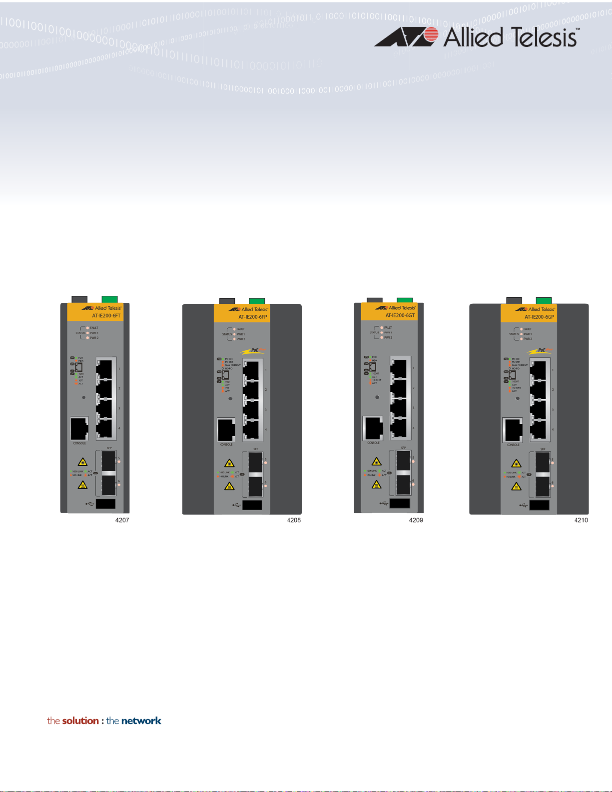
IE200 Series
Industrial Ethernet Switches
AT-IE200-6FT
AT-IE200-6FP
AT-IE200-6GT
AT-IE200-6GP
Installation Guide
613-001837 Rev. D

Copyright © 2017 Allied Telesis, Inc.
All rights reserved. No part of this publication may be reproduced without prior written permission from Allied Telesis, Inc.
Allied Telesis and the Allied Telesis logo are trademarks of Allied Telesis, Incorporated. All other product names, company names,
logos or other designations mentioned herein are trademarks or registered trademarks of their respective owners.
Allied Telesis, Inc. reserves the right to make changes in specifications and other information contained in this document without prior
written notice. The information provided herein is subject to change without notice. In no event shall Allied Telesis, Inc. be liable for
any incidental, special, indirect, or consequential damages whatsoever, including but not limited to lost profits, arising out of or related
to this manual or the information contained herein, even if Allied Telesis, Inc. has been advised of, known, or should have known, the
possibility of such damages.

Electrical Safety and Emissions Standards
This product meets the following standards:
U.S. Federal Communications Commission
Interference Statement
This device complies with part 15 of the FC C R ules. Operation is subject to the followi ng tw o co nd i ti on s :
(1) This device may not cause harmful interference, and (2) this device must accept any interference received, including
interference that may cause undesired operation.
This equipment has been tested and found to comply with the limits for a Class A digital device, pursuant to part 15 of the
FCC Rules. These limits are designed to provide reasonable protection against harmfu l interference in a controlled
environment, such as a cabinet, hut or telecom closet. This equipment generates, uses and can radiate radio frequency
energy and, if not installed and used in accordance with the instruction manual, may cause harmful interference to radio
communications. However, there is no guarantee that interference will not occur in a particular installation. If this
equipment does cause harmful interference to radio or television reception, which can be determined by turning the
equipment off and on, the user is encouraged to try to correct the interference by one or more of the following measures:
- Reorient or relocate the receiving antenna.
- Increase the separation between the equipment and receiver.
- Connect the equipment into an outlet on a circuit different from that to which the receiver is connected.
- Consult the dealer or an experienced radio/TV technician for help.
The Federal Communications Commission warns that changes or modifications of the unit not expressly approved by the
party responsible for compliance could void the user’s authority to operate the equipment and any assurances of safety
or performance, and could result in violation of part 15 of the FCC Rules.
Industry Canada
This Class A digital apparatus complies with Canadian ICES-003.
Cet appareil numérique de la classe A est conforme à la norme NMB-003 du Canada.
This equipment complies with radio frequency exposure limits set forth by Industry Canada for a controlled environment.
Cet éuipement est conforme aux limites d'exposition aux radiofréuences déinies par Industrie Canada pour un
environnement contré.
European Union Restriction of the Use of Certain Hazardous Substances
(RoHS) in Electrical and Electronic Equipment
This Allied Telesis RoHS-compliant product conforms to the European Union Restriction of the Use of Certain Hazardous
Substances (RoHS) in Electrical and Electronic Equipment. Allied Telesis ensures RoHS conformance by requiring
supplier Declarations of Conformity, monito ri n g incomin g materials, and maintaining manufacturing process controls.
The regulatory approvals of the product are listed here:
RFI Emissions
FCC Part 15B Class A
EN55032 Class A
EN61000-3-2
EN61000-3-3
VCCI-CISPR32:2016 Class A
ICES-003:Issue 6
3

RFI Immunity
EN55024
EN61000-4-2
EN61000-4-3
EN61000-4-4
EN61000-4-5
EN61000-4-6
EN61000-4-8
EN61000-4-11
Electrical and Laser Safety
UL/E/IEC60950-1
CSA 22.2:60950-1
2014/35/EU Low Voltage Directive
Shock
EN60068-2-27
IE200 Series Installation Guide
Free Fall
EN60068-2-31
Vibration
EN60068-2-6
Outdoor Enclosure Safety
UL/IEC/EN60950-22
Allied Telesis approved SFP modules
EN60825-1
EN60825-2
EN/IEC/UL60950-1
FCC CDRH registered
Warning: In a domestic environment this product may cause radio interference in
which case the user may be required to take adequate measures.
Laser Safety EN60825
4

IE200 Series Installation Guide
Translated Safety Statements
Important: The indicates that a translation of the safety statement is available in a PDF
document titled “Translated Safety Statements” on our web site at
http://www.alliedtelesis.com/support.
5

6

Contents
Preface ...............................................................................................................................................................................13
Safety Symbols Used in this Document...............................................................................................................................14
Contacting Allied Telesis .....................................................................................................................................................15
Chapter 1: Overview ........................................................................................................................................................ 17
Hardware Components........................................................................................................................................................18
Features ..............................................................................................................................................................................23
Twisted Pair Ports........................................................................................................................................................23
Power Over Ethernet....................................................................................................................................................23
SFP Slots .....................................................................................................................................................................23
LEDs.............................................................................................................................................................................24
Alarm Connectors.........................................................................................................................................................24
MAC Address Tables .................................................................................. ........................... ......................................24
Management Software .................................................................................................................................................24
Management Methods..................................................................................................................................................24
Installation Options.......................................................................................................................................................24
Additional Features ........................................... .................................... ... .......................... ..........................................24
Twisted Pair Ports ....................................................................... ........................................................................................26
Connector Type.............................................. .................................... ..........................................................................26
Speed...........................................................................................................................................................................26
Duplex Mode................................................................................................................................................................26
Maximum Distance.......................................................................................................................................................26
Cable Requirements.....................................................................................................................................................27
Automatic MDIX Detection ...........................................................................................................................................27
Port Pinouts........................................... ..................................... ..................................................................................27
Power over Ethernet............................................................................................................................................................28
PoE Versions................................................................................................................................................................28
Ethernet Cabling for PoE devices ................................................................................................................................28
Powered Device Classes for PoE and PoE+................................................................................................................29
PoE Wiring ...................................................................................................................................................................30
Power Budget...............................................................................................................................................................30
Port Prioritization..........................................................................................................................................................31
SFP Slots.............................................................................................................................................................................32
Console Port........................................................................................................................................................................33
USB Port..............................................................................................................................................................................34
Reset Button........................................................................................................................................................................34
Ground Screw......................................................................................................................................................................35
PWR 1 and PWR 2 DC Power Connectors............................................ ... ..................................... .. ... ................................35
Alarm In Connector..............................................................................................................................................................36
Alarm Out Connector...........................................................................................................................................................39
DIN Rail Bracket......................................... .. ..................................... ... ...............................................................................40
Screw Holes for Wall Brackets............................................................................................................................................40
LEDs....................................................................................................................................................................................41
Status LEDs .................................................................................................................................................................41
Twisted Pair Port LEDs................................................................................................................................................42
SFP Slot LEDs .............................................................................................................................................................46
Power Supplies....................................................................................................................................................................47
Optional Drip Guard.............................................................................................................................................................48
7

Contents
Chapter 2: Beginning the Installation ............................................................................................................................49
Reviewing Safety Precautions............................................................................................................................................ 50
Safety Precautions When Working with Electricity............................................................................................................. 54
Reviewing Site Requirements ............................................................................................................................................. 55
Verifying the Package Contents.......................................................................................................................................... 57
Chapter 3: Installing the Switch .....................................................................................................................................61
Installing the Switch on a DIN Rail...................................................................................................................................... 62
Installing the Switch on a Wood Wall.................................................................................................................................. 65
Installing the Switch on a Concrete Wall............................................................................................................................. 67
Chapter 4: Cabling the Ports ..........................................................................................................................................71
Cabling the Twisted Pair Ports............................................................................................................................................ 72
Installing SFP Transceivers................................................................................................................................................ 74
Chapter 5: Powering On the Switch ...............................................................................................................................79
Connecting the Grounding Wire.......................................................................................................................................... 80
Wiring the ALM IN and ALM OUT Connectors................................................................................................................... 83
Preparing the DC Power Cables.........................................................................................................................................88
Powering On the Switch......................................................................................................................................................92
Verifying Switch Operations......................................................................................................................................... 93
Monitoring the Initialization Process................................................................................................................................... 94
Starting a Local Management Session............................................................................................................................... 96
Installing the Optional Drip Guard.............................................................................................
Chapter 6: Troubleshooting ..........................................................................................................................................101
PWR 1 and PWR 2 LEDs ..................................................................................................... ............................................ 102
Twisted Pair Ports.............................................. .. ... .......................................................... ................................................ 103
SFP Slots.......................................................................................................................................................................... 105
Power Over Ethernet........................................................................................................................................................ 106
.......................................... 99
Appendix A: Technical Specifications .........................................................................................................................107
Physical Specifications .....................................................................................................................................................108
Environmental Specifications............................................................................................................................................ 110
Power Specifications......................................................................................................................................................... 112
Certifications..................................................................................................................................................................... 113
RJ-45 Twisted Pair Port Pinouts.......................................................................................................................................114
RJ-45 Style Serial Console Port Pinouts.......................................................................................................................... 116
PWR 1 and PWR 2 DC Power Connectors ............................. ... ... ....................................... ............................................ 117
8

Figures
Figure 1: Front Panel of the AT-IE200-6FT Switch...............................................................................................................18
Figure 2: Front Panel of the AT-IE200-6FP Switch..............................................................................................................19
Figure 3: Front Panel of the AT-IE200-6GT Switch..............................................................................................................20
Figure 4: Front Panel of the AT-IE200-6GP Switch..............................................................................................................21
Figure 5: Top Panel..............................................................................................................................................................21
Figure 6: Back Panel Features.............................................................................................................................................22
Figure 7: Example 1 of the Alarm In (ALM IN) Connector....................................................................................................37
Figure 8: Example 2 of the Alarm In (ALM IN) Connector....................................................................................................38
Figure 9: Example of the Alarm Out Port..............................................................................................................................40
Figure 10: Twisted Pair Port LEDs on the AT-IE200-6FT and AT-IE200-6GT Switches......................................................42
Figure 11: Twisted Pair Ports on the AT-IE200-6FP and AT-IE200-6GP Switches ........................................ .. ... ................44
Figure 12: Optional Drip Guard.............................................................................................................................................48
Figure 13: Pre-installed Components on the Front Panel.....................................................................................................57
Figure 14: Pre-installed Components on the Top Panel.......................................................................................................58
Figure 15: Pre-installed Component on the Back Panel.......................................................................................................59
Figure 16: Components in the Accessory Kit........................................................................................................................60
Figure 17: Orientation of the Switch on a DIN Rail...............................................................................................................62
Figure 18: Installing the Switch on a DIN Rail - 1 .................................................................................................................63
Figure 19: Installing the Switch on a DIN Rail - 2 .................................................................................................................63
Figure 20: Verifying the DIN Rail Installation........................................................................................................................64
Figure 21: Installing the Wall Brackets on the Switch...........................................................................................................65
Figure 22: Attaching the Switch to the Wall..........................................................................................................................66
Figure 23: Marking the Locations of the Bracket Holes on a Concrete Wall .................................... ....................................68
Figure 24: Installing the Switch on a Concrete Wall............................................................................
Figure 25: Removing the Dust Plug from an SFP Slot .........................................................................................................75
Figure 26: Installing an SFP Transceiver..............................................................................................................................75
Figure 27: Removing the Dust Cover from an SFP Transceiver ..........................................................................................76
Figure 28: Verifying the Position of the SFP Handle ............................................................................................................76
Figure 29: Connecting a Fiber Optic Cable to an SFP Transceiver......................................................................................77
Figure 30: Stripping the Grounding Wire..............................................................................................................................80
Figure 31: Loosening the Grounding Screw.........................................................................................................................81
Figure 32: Wrapping the Grounding Wire Around the Grounding Screw..............................................................................81
Figure 33: Securing the Grounding Wire to the Switch.........................................................................................................82
Figure 34: Polarity Legend for the Alarm Connectors...........................................................................................................84
Figure 35: Stripping an Alarm Wire.......................................................................................................................................84
Figure 36: Wrapping the Wire Strands.................................................................................................................................85
Figure 37: Removing an Alarm Connector ...........................................................................................................................85
Figure 38: Loosening the Wire Retaining Screws on an Alarm Connector............................................. ... ...........................86
Figure 39: Inserting the Wires into the DC Cable Connector................................................................................................86
Figure 40: Inserting the DC Connector into the Alarm Connector........................................................................................87
Figure 41: Pin Signals Legends for the PWR 1 and PWR 2 Connectors .............................................................................88
Figure 42: Stripping a Power Cable Wire.............................................................................................................................89
Figure 43: Removing the PWR 1 - PWR 2 Cable Connector ...............................................................................................89
Figure 44: Loosening the Wire Retaining Screws on the PWR 1 - PWR 2 Cable Connector...............................................90
Figure 45: Inserting the Wires into the PWR 1 - PWR 2 Cable Connector...........................................................................90
Figure 46: Verifying the Wire Installation..............................................................................................................................91
Figure 47: Connecting the Power Cable to the PWR 1 - PWR 2 Connector ........................................................................92
Figure 48: Initialization Messages........................................................................................................................................94
Figure 49: Initialization Messages (Continued).....................................................................................................................95
.................................69
9

Figures
Figure 50: Installing the Optional Drip Guard........................................................................................................................99
Figure 51: Securing the Drip Guard....................................................................................................................................100
Figure 52: RJ-45 Port Pin Layout (Front View)...................................................................................................................114
Figure 53: Console Port Pin Layout (Front View) ...............................................................................................................116
10

Tables
Table 1: Twisted Pair Cables ...............................................................................................................................................27
Table 2: Maximum Power Levels .........................................................................................................................................28
Table 3: Twisted Pair Cable for Powered Devices on the AT-IE200-6FP and AT-IE200-6GP Switches ............................29
Table 4: PoE and PoE+ Powered Device Classes ..............................................................................................................29
Table 5: Maximum Installation Site Temperatures Versus SFP Temperature Ratings .......................................................32
Table 6: Status LEDs ...........................................................................................................................................................41
Table 7: Twisted Pair Port LEDs on the AT-IE200-6FT Switch ...........................................................................................42
Table 8: Twisted Pair Port LEDs on the AT-IE200-6GT Switch ...........................................................................................43
Table 9: Twisted Pair Port LEDs on the AT-IE200-6FP Switch ...........................................................................................44
Table 10: Twisted Pair Port LEDs on the AT-IE200-6GP Switch ........................................................................................45
Table 11: SFP Slot LED ......................................................................................................................................................46
Table 12: Ground Resistivity Recommendations .................................................................................................................56
Table 13: Product Dimensions ...........................................................................................................................................108
Table 14: Product Weights ................................................................................................................................................108
Table 15: Ventilation Requirements for Cabinet Installation ..............................................................................................108
Table 16: Minimum Cabinet Dimensions ...........................................................................................................................109
Table 17: Environmental Specifications .............................................................................................................................110
Table 18: Ingress Protection ..............................................................................................................................................110
Table 19: Vibration, Shock, and Rough Handling Specifications for the AT-IE200-6FT and AT-IE200-6GT Switches .....110
Table 20: Vibration, Shock, and Rough Handling Specifications for the AT-IE200-6FP and AT-IE200-6GP Switches ....111
Table 21: Maximum Power Consumptions ........................................................................................................................112
Table 22: Input Power Specifications ................................................................................................................................112
Table 23: Heat Dissipation (British Thermal Units/Hour) ...................................................................................................112
Table 24: Regulatory Approvals ........................................................................................................................................113
Table 25: Pin Signals for RJ-45 Twisted Pair Ports at 10 and 100 Mbps ..........................................................................114
Table 26: Pin Signals for RJ-45 Twisted Pair Ports at 1000 Mbps ....................................................................................114
Table 27: RJ-45 Style Console Port Pin Signals ...............................................................................................................116
Table 28: PWR 1 and PWR 2 DC Connector Pin Signals on the AT-IE200-6FT and AT-IE200-6GT Switches ................117
Table 29: PWR 1 and PWR 2 DC Connector Pin Signals on the AT-IE200-6FP and AT-IE200-6GP Switches ...............117
11

Tables
12

Preface
This guide contains the hardware installation instructions for the IE200
Series of industrial managed switches. The preface contains the following
sections:
“Safety Symbols Used in this Document” on page 14
“Contacting Allied Telesis” on page 15
13
Preface
Note
Caution
Warning
Warning
Warning
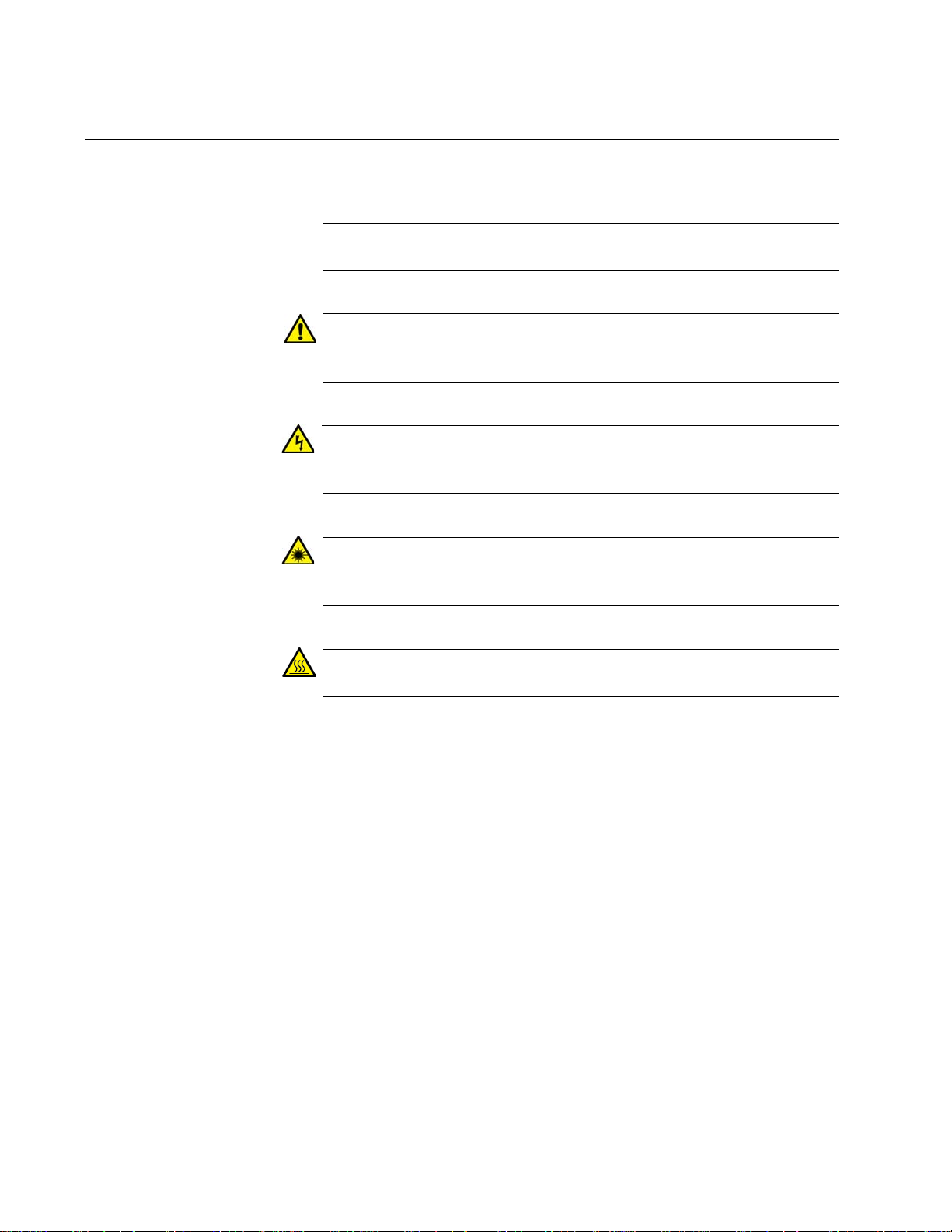
Safety Symbols Used in this Document
This document uses the following conventions.
Notes provide additional information.
Cautions inform you that performing or omitting a specific action
may result in equipment damage or loss of data.
Warnings inform you that performing or omitting a specific action
may result in bodily injury.
Laser warnings inform you that an eye or skin hazard exists due to
the presence of a Class 1 laser device.
Warnings inform you of hot surfaces.
14

Contacting Allied Telesis
If you need assistance with this product, you may contact Allied Telesis
technical support by going to the Support & Services section of the Allied
Telesis web site at www.alliedtelesis.com/support. You can find links for
the following services on this page:
24/7 Online Support — Enter our interactive support center to
search for answers to your product questions in our knowledge
database, to check support tickets, to learn about RMAs, and to
contact Allied Telesis technical experts.
USA and EMEA phone support — Select the phone number that
best fits your location and customer type.
Hardware warranty information — Learn about Allied Telesis
warranties and register your product online.
Replacement Services — Submit a Return Merchandise
Authorization (RMA) request via our interactive support center.
IE200 Series Installation Guide
Documentation — View the most recent installation and user
guides, software release notes, white papers, and data sheets for
your products.
Software Downloads — Download the latest software releases for
your managed products.
For sales or corporate information, go to www.alliedtelesis.com/
purchase and select your region.
15

Preface
16

Chapter 1
Overview
This chapter describes the hardware features of the IE200 Series of
managed industrial switches. The sections in the chapter are listed here:
“Hardware Components” on page 18
“Features” on page 23
“Twisted Pair Ports” on page 26
“Power over Ethernet” on page 28
“SFP Slots” on page 32
“Console Port” on page 33
“USB Port” on page 34
“Reset Button” on page 34
“Ground Screw” on page 35
“PWR 1 and PWR 2 DC Power Connectors” on page 35
“Alarm In Connector” on page 36
“Alarm Out Connector” on page 39
“DIN Rail Bracket” on page 40
“Screw Holes for Wall Brackets” on page 40
“LEDs” on page 41
“Power Supplies” on page 47
“Optional Drip Guard” on page 48
17
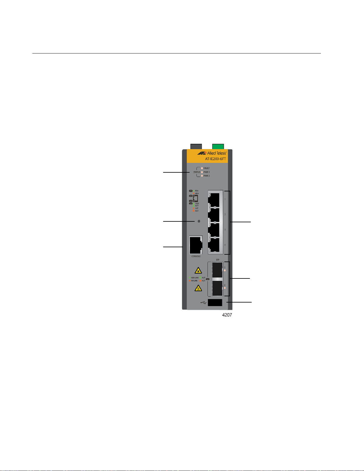
Chapter 1: Overview
Four 10/100Base-TX
twisted pair ports
Two slots for
100/1000Base-FX
SFP transceivers
Console
management
port
USB port
Status LEDs
Reset button
Hardware Components
The switches in the IE200 Series are listed here:
AT-IE200-6FT
AT-IE200-6FP
AT-IE200-6GT
AT-IE200-6GP
The front panel of the AT-IE200-6FT Switch is shown in Figure 1.
18
Figure 1. Front Panel of the AT-IE200-6FT Switch
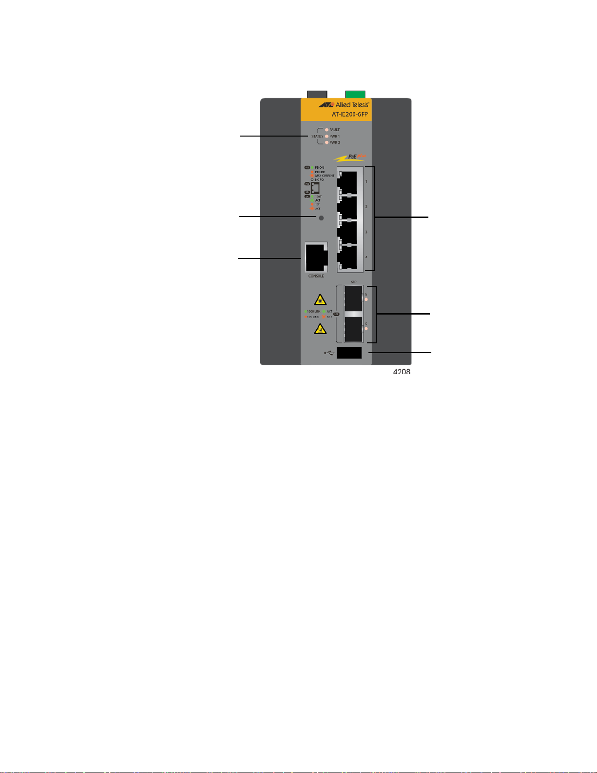
IE200 Series Installation Guide
Four 10/100Base-TX
twisted pair ports
with PoE and PoE+
Two slots for
100/1000Base-FX
SFP transceivers
Console
management
port
USB port
Status LEDs
Reset button
The front panel of the AT-IE200-6FP Switch is shown in Figure 2.
Figure 2. Front Panel of the AT-IE200-6FP Switch
19
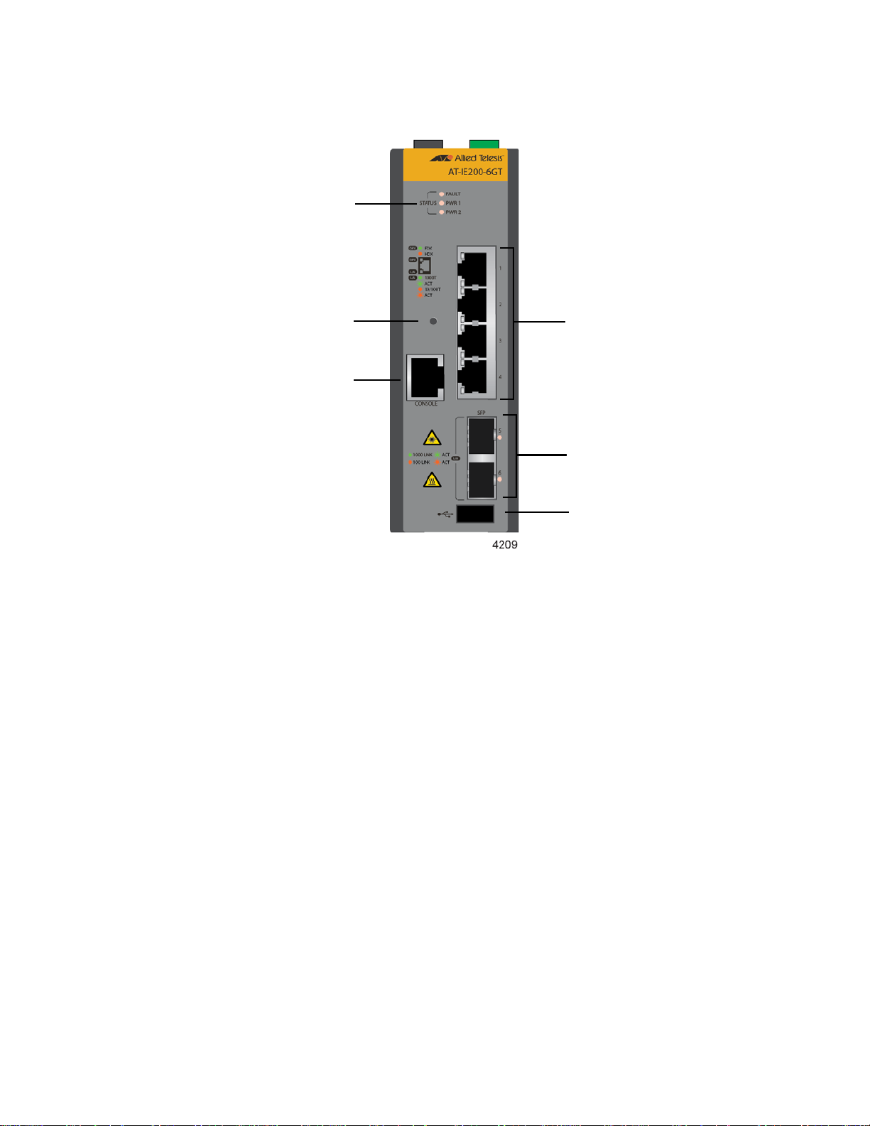
Chapter 1: Overview
Four 10/100/1000Base-T
twisted pair ports
Two slots for
100/1000Base-FX SFP
transceivers
Console
management
port
USB port
Status LEDs
Reset button
The front panel of the AT-IE200-6GT Switch is shown in Figure 3.
Figure 3. Front Panel of the AT-IE200-6GT Switch
20
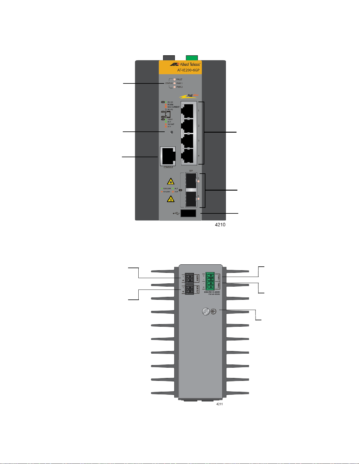
IE200 Series Installation Guide
Four 10/100/1000Base-T
twisted pair ports with PoE
and PoE+
Two slots for
100/1000Base-FX SFP
transceivers
Console
management
port
USB port
Status LEDs
Reset button
PWR 2 DC
power connector
PWR 1 DC
power connector
Alarm In
connector
Alarm Out
connector
Grounding screw
The front panel of the AT-IE200-6GP Switch is shown in Figure 4.
Figure 4. Front Panel of the AT-IE200-6GP Switch
Figure 5 identifies the components on the top panel.
Figure 5. Top Panel
21
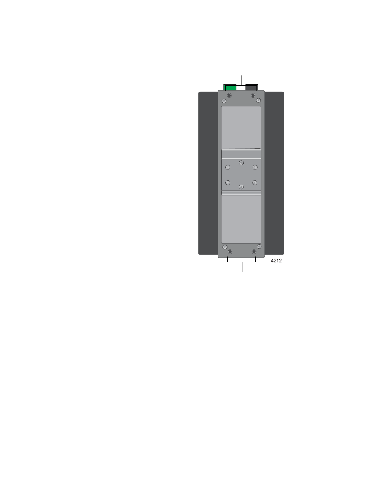
Chapter 1: Overview
Screw holes for
wall bracket
DIN rail
bracket
Screw holes for
wall bracket
Figure 6 identifies the components on the back panel.
Figure 6. Back Panel Features
22

Features
IE200 Series Installation Guide
Here are the basic features of the switches.
Twisted Pair
Ports
Power Over
Ethernet
Here are the basic features of the twisted pair ports:
4 ports per switch
10Base-T and 100Base-TX compliant on the AT-IE200-6FT and
AT-IE200-6FP Switches
10Base-T, 100Base-TX, and 1000Base-T compliant on the AT-
IE200-6GT and AT-IE200-6GP Switches
IEEE 802.3u Auto-Negotiation compliant
Auto-MDI/MDIX
100 meters (328 feet) maximum operating distance
IEEE 802.3x flow control in 10/100Base-TX full-duplex mode
IEEE 802.3ab 1000Base-T
Jumbo frames up to 9KB
RJ-45 connectors
Ports 1 to 4 on the AT-IE200-6FP and AT-IE200-6GP Switches have these
Power over Ethernet features:
Support PoE (15 watts) and PoE+ (30 watts)
Powered device classes 0 to 4
Maximum PoE budget of 120 watts with one or two power supplies
Port prioritization
Alternative A wiring
SFP Slots The two SFP slots support the following types of transceivers:
100Base-FX transceivers
1000Base-SX/LX transceivers
Single-port Bi-directional (BiDi) 1000Base-LX transceivers
1000Base-ZX transceivers
1000Base-T twisted pair transceivers
SFP transceivers must be purchased separately. Refer to the product
datasheet for a list of supported transceivers.
23

Chapter 1: Overview
LEDs The switches have the following LEDs:
Link/activity and duplex mode LEDs for the twisted pair ports on
the AT-IE200-6FT and AT-IE200-6GT Switches.
Link/activity and PoE status LEDs for the twisted pair ports on the
AT-IE200-6FP and AT-IE200-6GP Switches.
Link/activity LEDs for the SFP ports.
Fault and power supply status LEDs
Alarm
Connectors
MAC Address
Tables
Management
Software
Management
Methods
The switches have two alarm connectors:
Alarm In connector for an external sensor, such as a motion
detector or door relay, to monitor the wiring closet or cabinet.
Alarm Out connector for an external alert device, such as a buzzer
or LED, for switch alarms.
Here are the basic features of the MAC address tables:
Storage capacity of 2,000 MAC address entries
Automatic learning and aging
The switches support the following management software and interfaces:
AlliedWare Plus management software
Command line interface
Web browser interface
You can manage the switches in the following ways:
Local management through the Console port
24
Installation
Options
Additional
Features
Remote Telnet or secure shell management
Remote HTTP or HTTPS web browser management
SNMPv1, v2c, or v3
The switches support the following installation options:
DIN rail installation (compatible with DIN 35x7.5mm rails)
Concrete or wood wall
Here are additional features:
Slot for USB flash memory
Reset button
Two DC power supply connectors

Extended environmental range
IP30-compliant without optional drip guard
IP31-compliant with optional drip guard
RJ-45 style Console port for local management
IE200 Series Installation Guide
25

Chapter 1: Overview
Note
Twisted Pair Ports
This section describes the four twisted pair ports.
Connector Type The twisted-pair ports have 8-pin RJ-45 connectors. The ports use four
pins at 10 or 100 Mbps and all eight pins at 1000 Mbps. The pin
assignments are listed in Table 25 on page 114 and Table 26 on
page 114.
Speed The port speeds of the twisted pair ports are listed here:
AT-IE200-6FT and AT-IE200-6FP Switches - 10 or 100Mbps
AT-IE200-6GT and AT-IE200-6GP Switches - 10, 100, or
1000Mbps
The switches can set the speeds automatically with Auto-Negotiation, the
default setting, or you can manually set the speeds with the AlliedWare
Plus operating system.
Duplex Mode The twisted-pair ports can operate in either half- or full-duplex mo de a t 10
or 100 Mbps. Ports operating at 1000 Mbps can only operate in full-dup lex
mode. The twisted-pair ports are IEEE 802.3u Auto-Negotiation compliant.
The switch can set the duplex modes automatically or you can disable
Auto-Negotiation and set the duplex modes manually.
Speed and duplex mode settings can be set independently of each other
on the ports. For example, the speed of a port can be configured manually
while its duplex mode is established through Auto-Negotiation.
Switch ports connected to 10 or 100 Mbps end nodes that do not
support Auto-Negotiation should not use Auto-Negotiation to set
their speed and duplex mode settings, because duplex mode
mismatches might occur. You should disable Auto-Negotiation and
set the speed and duplex mode settings manually with the
AlliedWare Plus operating system.
Maximum
The ports have a maximum operating distance of 100 meters (328 feet).
Distance
26

IE200 Series Installation Guide
Cable
Requirements
The cable requirements for the twisted pair ports are listed in Table 1.
Table 1. Twisted Pair Cables
Cable Type 10Mbps 100Mbps 1000Mbps
Standard TIA/EIA 568-Bcompliant Category 3 shielded
or unshielded cabling with 100
ohm impedance and a
frequency of 16 MHz.
Standard TIA/EIA 568-Acompliant Category 5 or TIA/
EIA 568-B-compliant Enhanced
Category 5 (Cat 5e) shielded or
unshielded cabling with 100
ohm impedance and a
frequency of 100 MHz.
Standard TIA/EIA 568-Bcompliant Category 6 or 6a
shielded cabling.
Yes Yes No
Yes Yes Yes
Yes Yes Yes
Automatic MDIX
Detection
The twisted-pair ports are IEEE 802.3ab compliant, with automatic MDIX
detection at 10 or 100 Mbps. (Automatic MDIX detection does not apply to
1000 Mbps.) This feature automatically configures the ports to MDI or
MDI-X depending on the wiring configurations of the end nodes.
Switch ports connected to network devices that do not support automatic
MDIX detection default to MDIX.
You may disable automatic MDIX detection on the individual ports and
configure the MDI/MDI-X settings manually.
Port Pinouts Refer to Table 25 on page 114 for the pinouts of the twisted-pair ports at
10 or 100 Mbps and to Table 26 on page 114 for the port pinouts at 1000
Mbps.
27

Chapter 1: Overview
Power over Ethernet
Ports 1 to 4 on the AT-IE200-6FP and AT-IE200-6GP Switches support
Power over Ethernet (PoE). With PoE, the switch can supply electrical
power to network devices over the same twisted pair cables that carry
network traffic. The feature can simplify network installation and
maintenance because it allows you to use the switch as a central power
source for other network devices.
Devices that receive their power over Ethernet cables are called powered
devices (PD). Examples of PDs include wireless access points, IP
telephones, web cams, and even other Ethernet switches. A PD
connected to a port on the switch receives both network traffic and power
over the same twisted-pair cable.
PoE Versions The AT-IE200-6FP and AT-IE200-6GP Switches support the following
versions of Power over Ethernet:
PoE (IEEE 802.3af)
Ethernet Cabling
for PoE devices
PoE+ (802.3at)
Table 2 lists the switch ports that support PoE and the maximum power
levels.
Table 2. Maximum Power Levels
Maximum
PoE Version Switch Ports
PoE 1 to 4 15.4W 12.95W
PoE+ 1 to 4 30.0W 25.9W
The cable requirements for the twisted pair ports on the AT-IE200-6FP
and AT-IE200-6GP Switches for powered devices are given in Table 3 on
page 29. The cable requirements for ports connected to non-PoE devices
are given in Table 1 on page 27.
Power Output
at Switch Port
Maximum
Power at PD
28

IE200 Series Installation Guide
Table 3. Twisted Pair Cable for Powered Devices on the AT-IE200-6FP
and AT-IE200-6GP Switches
10Mbps 100Mbps 1000Mbps
Cable Type
PoE PoE+ PoE PoE+ PoE PoE+
Standard TIA/EIA 568B-compliant Category 3
shielded or unshielded
cabling with 100 ohm
impedance and a
frequency of 16 MHz.
Standard TIA/EIA 568A-compliant Category 5
shielded or unshielded
cabling with 100 ohm
impedance and a
frequency of 100 MHz.
Standard TIA/EIA 568B-compliant Enhanced
Category 5 (Cat 5e)
shielded or unshielded
cabling with 100 ohm
impedance and a
frequency of 100 MHz.
Standard TIA/EIA 568B-compliant Category 6
or 6a shielded cabling.
No No No No No No
Yes No Yes No Yes No
Yes Yes Yes Yes Yes Yes
Yes Yes Yes Yes Yes Yes
Powered Device
Classes for PoE
and PoE+
The PoE and PoE+ standards define five powered device classes. The
classes are defined by the power requirements of the powered devices.
The classes are shown in Table 4. The AT-IE200-6FP and AT-IE200-6GP
Switches support all five classes.
Table 4. PoE and PoE+ Powered Device Classes
Maximum
Class Usage
0 Default 15.4W .044W to
1 Optional 4.0W 0.44W to 3.84W
2 Optional 7.0W 3.84W to 6.49W
Power Output
at the Switch
Port
PD Power
Range
12.95W
29

Chapter 1: Overview
Note
PoE Wiring The IEEE 802.3af and 802.3at standards define two methods for
Table 4. PoE and PoE+ Powered Device Classes (Continued)
Maximum
Class Usage
3 Optional 15.4W 6.49W to
4 Optional 30.0W 12.95W to
delivering power to powered devices over the four pairs of strands in
standard Ethernet twisted-pair cable. The methods are called Alternatives
A and B. In Alternative A, power is supplied to powered devices on strands
1, 2, 3, and 6, which are the same strands that carry the 10/100Base-TX
network traffic. In Alternative B, power is delivered on strands 4, 5, 7, and
8. These are the unused strands.
Power Output
at the Switch
Port
PD Power
Range
12.95W
25.9W
1000BASE-T cables carry the network traffic on all eight strands of
the Ethernet cable.
The twisted pair ports on the AT-IE200-6FP and AT-IE200-6GP Switches
support Alternative A. They transmit power on strands 1, 2, 3, and 6.
Consequently, they can support PDs that also support Alternative A.
PDs that comply with the IEEE 802.3af and 802.3at standards are
required to support both power delivery methods. However, non-standard
PDs and PDs that were manufactured before the completion of the IEEE
802.3af and 802.3at standards and that support only Alternative B will not
work with the switches.
Power Budget The power budget is the total amount of DC power the AT-IE200-6FP or
AT-IE200-6GP Switch can supply to the powered devices on its ports.
These switches have a maximum power budget of 120W.
The number of powered devices the switch can support at one time will
depend on the switch’s power budget and the power requirements of the
powered devices. As long as the total power requirements of the powered
devices is less than the power budget of the switch, the switch can supply
power to all the devices. If the total power requirements exceed the power
budget, the switch denies power to one or more ports using a mechanism
referred to as port prioritization.
To determine whether the power requirements of the PoE devices you
30
 Loading...