

Page 1

User’s Guide
Management
Software
AT-S82
For the AT-GS950/8 Layer 2 Gigabit Ethernet WebSmart Switch
Version 1.1.0
613-000375 Rev. B
Page 2

Copyright © 2007 Allied Telesis, Inc.
All rights reserved. No part of this publication may be reproduced without prior written permission from Allied Telesis, Inc.
Allied Telesis is a trademark of Allied Telesis, Inc. Microsoft and Internet Explorer are registered trademarks of Microsoft
Corporation. Netscape Navigator is a registered trademark of Netscape Communications Corporation. All other product names,
company names, logos or other designations mentioned herein are trademarks or registered trademarks of their respective
owners.
Allied Telesis, Inc. reserves the right to make changes in specifications and other information contained in this document without
prior written notice. The information provided herein is subject to change without notice. In no event shall Allied Telesis, Inc. be
liable for any incidental, special, indirect, or consequential damages whatsoever, including but not limited to lost profits, arising
out of or related to this manual or the information contained herein, even if Allied Telesis, Inc. has been advised of, known, or
should have known, the possibility of such damages.
Page 3

Contents
Preface .............................................................................................................................................................. 7
Where to Find Web-based Guides ..................................................................................................................... 8
Contacting Allied Telesis .................................................................................................................................... 9
Online Support ............................................................................................................................................. 9
Email and Telephone Support...................................................................................................................... 9
Warranty....................................................................................................................................................... 9
Returning Products ...................................................................................................................................... 9
Sales or Corporate Information .................................................................................................................... 9
Management Software Updates................................................................................................................... 9
Chapter 1: Getting Started ............................................................................................................................ 11
Starting a Management Session ...................................................................................................................... 12
Saving Changes ............................................................................................................................................... 14
Quitting a Management Session ...................................................................................................................... 15
Chapter 2: Basic Switch Parameters ........................................................................................................... 17
Configuring the IP Address, Subnet Mask, Gateway Address, and BOOTP or DHCP .................................... 18
Disabling or Enabling Ping Blocking................................................................................................................. 20
Enabling or Disabling 802.1X Forwarding Control............................................................................................ 21
Changing the Administrator’s Password........................................................................................................... 22
Rebooting the Switch........................................................................................................................................ 23
Resetting the Switch and Retaining the IP Address ......................................................................................... 24
Returning the AT-S82 Management Software to the Factory Default Values .................................................. 25
Downloading New Firmware............................................................................................................................. 26
Chapter 3: Port Configuration ...................................................................................................................... 27
Configuring Port Parameters ............................................................................................................................ 28
Chapter 4: Trunking ...................................................................................................................................... 31
Trunking Overview............................................................................................................................................ 32
Trunking Guidelines ................................................................................................................................... 32
Trunking Algorithm ..................................................................................................................................... 32
Configuring the Trunking Algorithm .................................................................................................................. 34
Setting up the Trunk ......................................................................................................................................... 35
Chapter 5: Port Mirroring .............................................................................................................................. 37
Port Mirroring Overview.................................................................................................................................... 38
Configuring Port Mirroring ................................................................................................................................ 39
Chapter 6: VLANs .......................................................................................................................................... 41
VLAN Features ................................................................................................................................................. 42
Increased Performance.............................................................................................................................. 42
Improved Manageability ............................................................................................................................. 42
Increased Security ..................................................................................................................................... 42
VLAN Overview ................................................................................................................................................ 44
VLAN Name ............................................................................................................................................... 44
VLAN Identifier ........................................................................................................................................... 44
VLAN Port Members .................................................................................................................................. 44
3
Page 4

Contents
Tagged Port Members ......................................................................................................................... 45
Untagged Port Members ...................................................................................................................... 45
Incoming and Outgoing Tagged and Untagged Frames ............................................................................ 45
Incoming Frames ................................................................................................................................. 45
Outgoing Frames ................................................................................................................................. 45
Guidelines for Creating a VLAN ................................................................................................................. 46
Working with VLANs ......................................................................................................................................... 47
Creating a VLAN......................................................................................................................................... 47
Displaying all VLANs .................................................................................................................................. 48
Modifying a VLAN....................................................................................................................................... 49
Deleting a VLAN ......................................................................................................................................... 49
Protected Ports VLAN .......................................................................................................................................50
Chapter 7: Class of Service .......................................................................................................................... 53
Class of Service Overview ................................................................................................................................ 54
Mapping Ports to Egress Queues............................................................................................................... 54
Scheduling.................................................................................................................................................. 55
Mapping Priorities to Queues............................................................................................................................57
Setting Up the Schedule ................................................................................................................................... 58
Assigning Priority to Ports ................................................................................................................................. 59
Chapter 8: Spanning Tree Protocol (STP) ................................................................................................... 61
Spanning Tree Overview ..................................................................................................................................62
Bridge Priority and the Root Bridge ............................................................................................................ 62
Path Costs and Port Costs...................................................................................................................63
Port Priority .......................................................................................................................................... 65
Forwarding Delay and Topology Changes...........................................................................................65
Hello Time and Bridge Protocol Data Units (BPDUs) .......................................................................... 66
Point-to-Point and Edge Ports..............................................................................................................67
Spanning Tree and VLANs.........................................................................................................................69
Configuring Spanning Tree ............................................................................................................................... 71
Configuring STP Port Settings .......................................................................................................................... 74
4
Page 5

Figures
Figure 1. Login Dialog Box ..................................................................................................................................................12
Figure 2. Main Page ............................................................................................................................................................13
Figure 3. Save Configuration Page .....................................................................................................................................14
Figure 4. Basic Switch Information Page.............................................................................................................................18
Figure 5. Administrator Password Page ..............................................................................................................................22
Figure 6. Reboot Page ........................................................................................................................................................23
Figure 7. Reset Page...........................................................................................................................................................24
Figure 8. Reset System Page..............................................................................................................................................25
Figure 9. Download Firmware Page ....................................................................................................................................26
Figure 10. Download Status Message.................................................................................................................................26
Figure 11. Port Configuration Page .....................................................................................................................................28
Figure 12. Trunking Algorithm Page....................................................................................................................................34
Figure 13. Port Trunking Page ............................................................................................................................................35
Figure 14. Port Trunking Configuration Page ......................................................................................................................35
Figure 15. Port Mirroring Page ............................................................................................................................................39
Figure 16. 802.1Q Static VLAN Page..................................................................................................................................47
Figure 17. VLAN Detail Page ..............................................................................................................................................47
Figure 18. Current VLANs Page..........................................................................................................................................49
Figure 19. Protected Ports VLAN Example .........................................................................................................................50
Figure 20. Protected Port Page for Figure 19......................................................................................................................50
Figure 21. Protected Port Page ...........................................................................................................................................51
Figure 22. CoS Priority to Queue Page ...............................................................................................................................57
Figure 23. Output Scheduling Page ....................................................................................................................................58
Figure 24. CoS Port Priority Assignment Page....................................................................................................................59
Figure 25. Point-to-Point Ports ............................................................................................................................................67
Figure 26. Edge Port ...........................................................................................................................................................68
Figure 27. Point-to-Point and Edge Port..............................................................................................................................68
Figure 28. VLAN Fragmentation..........................................................................................................................................69
Figure 29. Switch Spanning Tree Settings Page.................................................................................................................71
Figure 30. STP Port Settings Page .....................................................................................................................................74
5
Page 6

Figures
6
Page 7

Preface
This guide contains instructions on how to use the AT-S82 management
software to manage the AT-GS950/8 Smart Switch switch.
This preface contains the following sections:
“Where to Find Web-based Guides” on page 8
“Contacting Allied Telesis” on page 9
7
Page 8

Preface
Where to Find Web-based Guides
The installation and user guides for all Allied Telesis products are
available in portable document format (PDF) on our web site at
www.alliedtelesis.com. You can view the documents online or download
them onto a local workstation or server.
8
Page 9

AT-S82 Management Software User’s Guide
Contacting Allied Telesis
This section provides Allied Telesis contact information for technical
support as well as sales and corporate information.
Online Support You can request technical support online by accessing the Allied Telesis
Knowledge Base from the following website: www.alliedtelesis.com/
support. You can use the Knowledge Base to submit questions to our
technical support staff and review answers to previously asked questions.
Email and
Telephone
Support
Warranty For hardware warranty information, refer to the Allied Telesis web site:
Returning
Products
Sales or
Corporate
Information
Management
Software Updates
For Technical Support via email or telephone, refer to the Allied Telesis
web site: www.alliedtelesis.com. Select your country from the list
displayed on the website. Then select the appropriate menu tab.
www.alliedtelesis.com/support/warranty.
Products for return or repair must first be assigned a return materials
authorization (RMA) number. A product sent to Allied Telesis without an
RMA number will be returned to the sender at the sender’s expense.
To obtain an RMA number, contact the Allied Telesis Technical Support
group at our web site: www.alliedtelesis.com/support/rma. Select your
country from the list displayed on the website. Then select the appropriate
menu tab.
You can contact Allied Telesis for sales or corporate information through
our web site: www.alliedtelesis.com. To find the contact information for
your country, select Contact Us -> Worldwide Contacts.
New releases of management software for our managed products are
available from either of the following Internet sites:
Allied Telesis web site: www.alliedtelesis.com
Allied Telesis FTP server: ftp://ftp.alliedtelesis.com
To download new software from the Allied Telesis FTP server from your
workstation’s command prompt, you must have FTP client software.
Additionally, you must log in to the server. The user name is “anonymous”
and your email address is the password.
9
Page 10

Preface
10
Page 11

Chapter 1
Getting Started
This chapter provides information and instructions on how to access the
AT-S82 management software by starting a web browser management
session. This chapter contains the following sections:
“Starting a Management Session” on page 12
“Saving Changes” on page 14
“Quitting a Management Session” on page 15
11
Page 12
Chapter 1: Getting Started
Starting a Management Session
You establish a local management session with the AT-GS950/8 switch by
connecting an Ethernet cable to one of the eight ports on the front panel of
the switch.
To start a management session, perform the following procedure:
1. Start a web browser.
2. In the URL field of the web browser, enter the default IP address of the
switch: 192.168.1.1
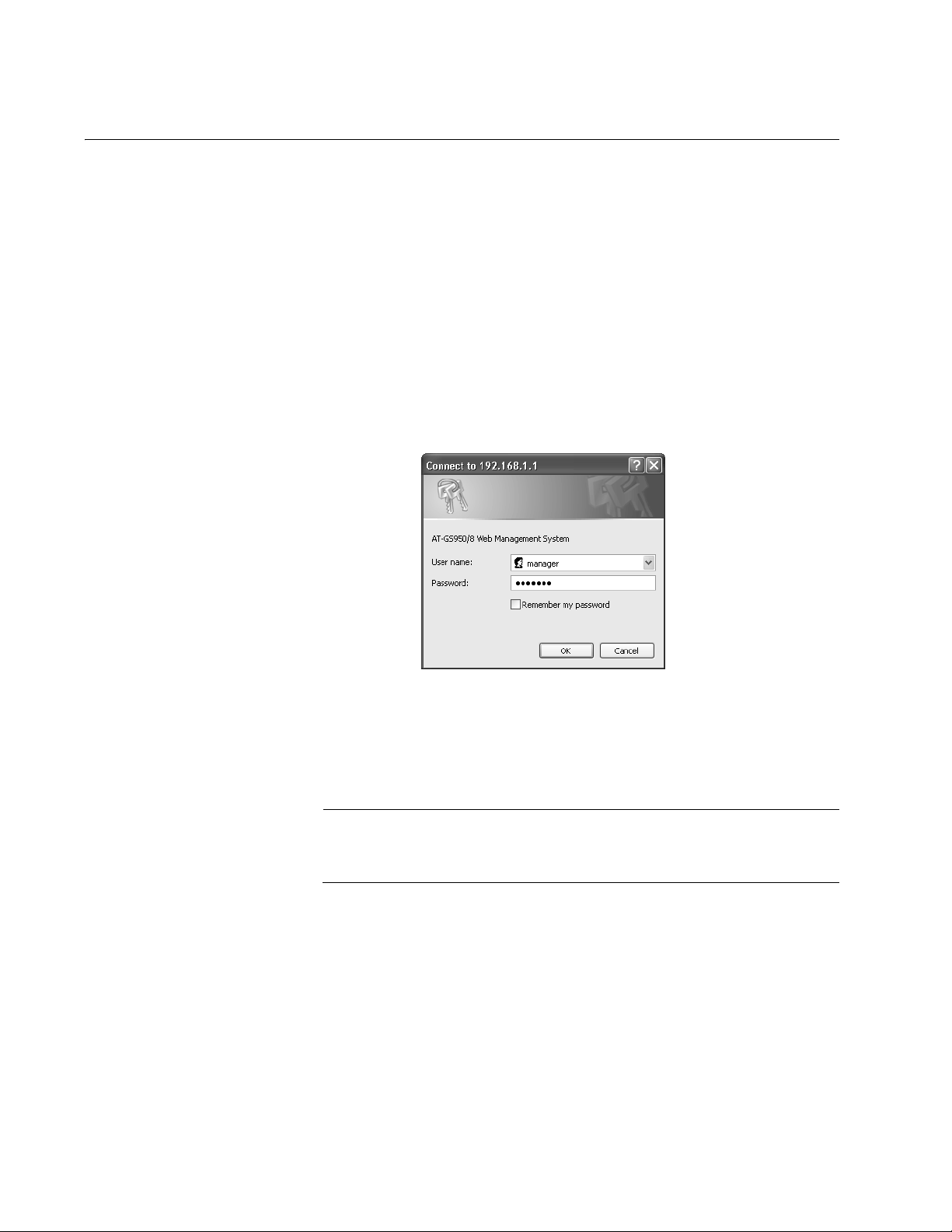
The AT-S82 management software displays the login dialog box
shown in Figure 1.
Figure 1. Login Dialog Box
3. Enter the administrator’s default name, manager.
4. Enter the administrator’s default password, friend.
Note
To change the administrator’s password, refer to “Changing the
Administrator’s Password” on page 22.
12
Page 13
AT-S82 Management Software User’s Guide
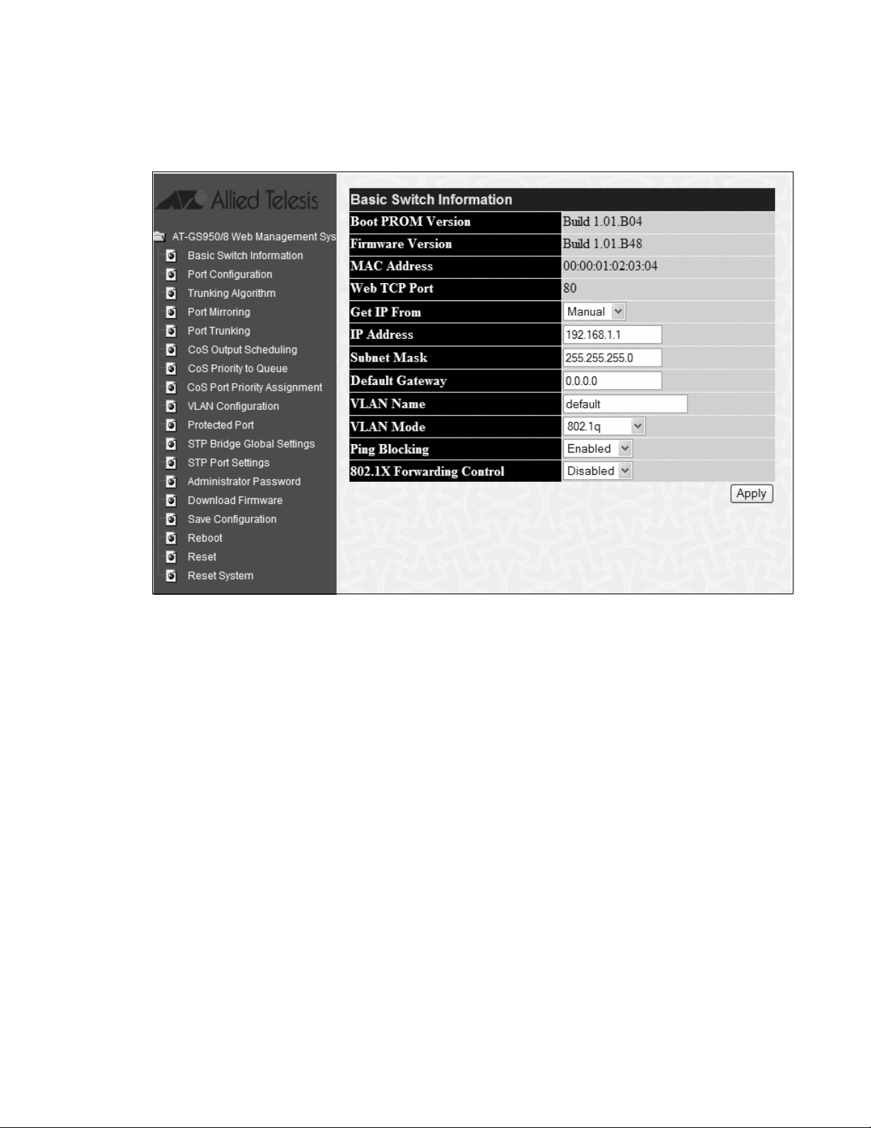
The main page, which by default displays the Basic Switch Information
page, is shown in Figure 2.
Figure 2. Main Page
13
Page 14
Chapter 1: Getting Started
Saving Changes
The management software applies the changes you make when you click
the Apply button on any web page. However, the management software
does not automatically save the changes you make to the configuration
file. You can save your changes to the configuration file each time that you
change a parameter, or save the changes after you are done with all your
changes and before you exit the web browser.
Note
If you do not save changes using the Save Configuration page, your
changes are lost when the switch is rebooted.
To save your configuration changes, perform the following procedure:
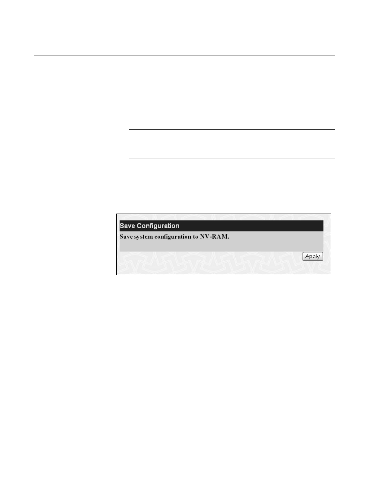
1. From the main menu, select Save Configuration.
The Save Configuration page is shown in Figure 3.
.
14
Figure 3. Save Configuration Page
2. Click Apply.
Page 15

Quitting a Management Session
To quit a management session, close the web browser.
AT-S82 Management Software User’s Guide
15
Page 16

Chapter 1: Getting Started
16
Page 17

Chapter 2
Basic Switch Parameters
This chapter contains the following sections:
“Configuring the IP Address, Subnet Mask, Gateway Address, and
BOOTP or DHCP” on page 18
“Disabling or Enabling Ping Blocking” on page 20
“Enabling or Disabling 802.1X Forwarding Control” on page 21
“Changing the Administrator’s Password” on page 22
“Rebooting the Switch” on page 23
“Resetting the Switch and Retaining the IP Address” on page 24
“Returning the AT-S82 Management Software to the Factory Default
Values” on page 25
“Downloading New Firmware” on page 26
17
Page 18
Chapter 2: Basic Switch Parameters
Configuring the IP Address, Subnet Mask, Gateway Address, and BOOTP or DHCP
Caution
Allied Telesis strongly recommends that you record the MAC
address of this switch, as shown on the Basic Switch Information
Page (Figure 4) before you configure or enable the BOOTP or
DHCP options of the Get IP From parameter. After you enable
either option, contact your network administrator for the IP address
from the BOOTP or DHCP server that corresponds to the switch’s
MAC address.
This procedure explains how to assign an IP address, subnet mask, and
gateway address to the switch.
To set the switch’s IP configuration, perform the following procedure:
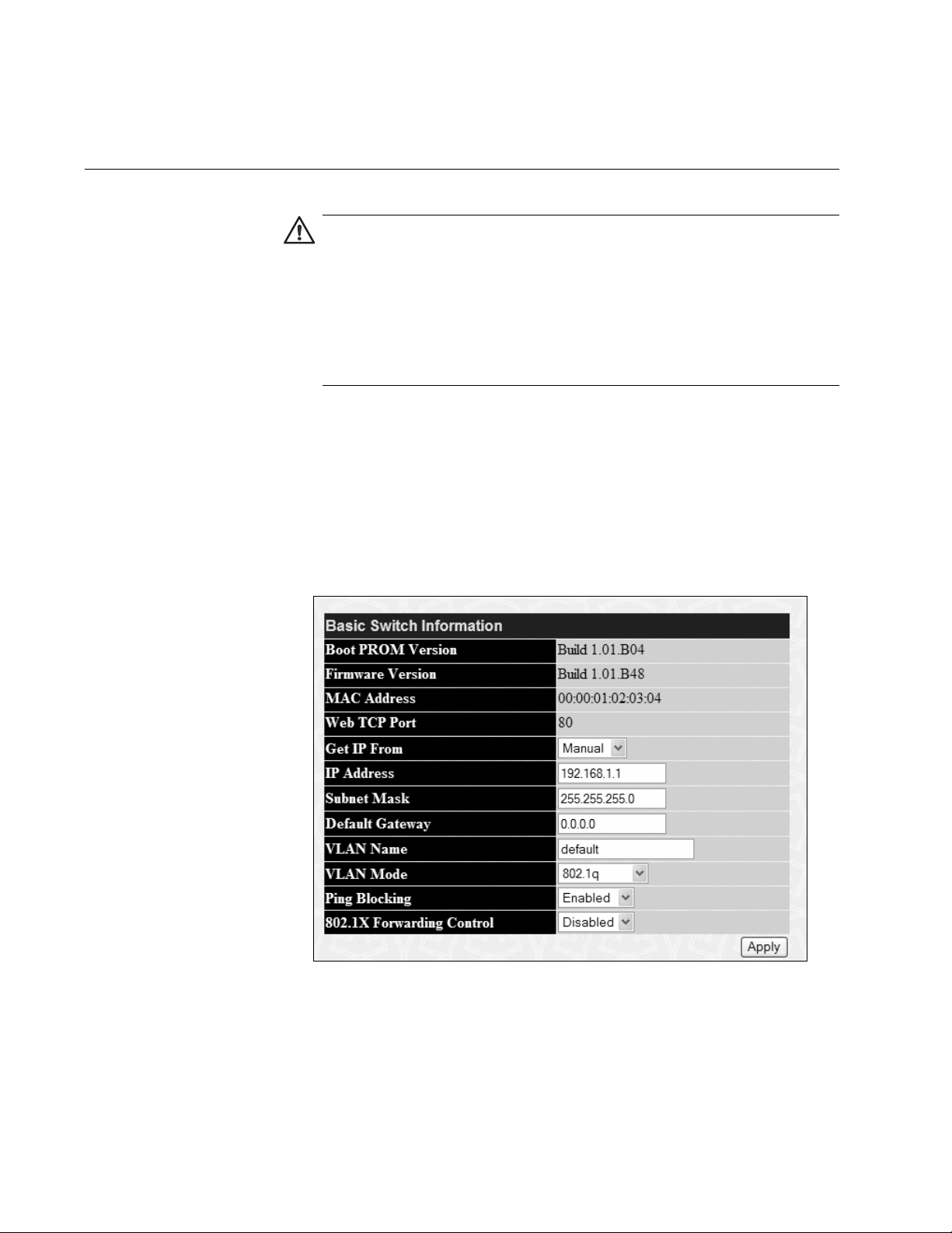
1. From the main menu, select Basic Switch Information.
The Basic Switch Information page is shown in Figure 4.
18
Figure 4. Basic Switch Information Page
2. To set the switch’s IP address, in the Get IP From field, choose one of
the following from the list:
Manual - Allows you to enter static IP address information:
Page 19

AT-S82 Management Software User’s Guide
a. In the IP Address field, enter the IP address. The default is
192.168.1.1.
b. In the Subnet Mask field, type the subnet mask for the switch. The
default is 255.255.255.0.
c. In the Default Gateway field, type the IP address of the default
gateway. There is no default gateway assigned.
BOOTP - Enables BOOTP so that the switch gets its IP address from a
BOOTP server. When you choose this selection, the IP Address,
Subnet Mask, and Default Gateway fields are not available.
DHCP - Enables DHCP so that the switch gets its IP address from a
DHCP server. When you choose this selection, the IP Address, Subnet
Mask, and Default Gateway fields are not available.
3. Click Apply to implement your changes.
Note
For BOOTP and DHCP options: In order to save this new
configuration, you must contact the switch using its newly acquired
IP address in order to perform steps 4 and 5 below. If the switch is
rebooted or power cycled before you save the configuration, the IP
address is reset to the factory default value of 192.168.1.1 and
Manual mode.
4. To save the settings to the configuration file, from the main menu,
select Save Configuration.
The Save Configuration page is shown in Figure 3 on page 14.
5. Click Apply.
19
Page 20

Chapter 2: Basic Switch Parameters
Disabling or Enabling Ping Blocking
You can allow the switch to respond to ping requests by setting the Ping
Blocking parameter. The default setting is enabled, which means that the
switch does not respond to ping requests.
To disable or enable ping blocking, perform the following procedure:
1. From the main menu, select Basic Switch Information.
The Basic Switch Information page is shown in Figure 4 on page 18.
2. For Ping Blocking, choose one of the following:
Enabled
The switch does not respond to ping requests. This is the default.
Disabled
The switch responds to ping requests. Allied Telesis recommends that
you choose this setting.
3. Click Apply to implement your changes.
4. To save the settings to the configuration file, from the main menu,
select Save Configuration.
The Save Configuration page is shown in Figure 3 on page 14.
5. Click Apply.
20
Page 21

Enabling or Disabling 802.1X Forwarding Control
This procedure describes how to enable or disable 802.1x forwarding
control. The default setting is disabled. When you disable this feature,
802.1x packets are not forwarded. If this feature is enabled, these packets
are forwarded to their destination which might be a switch running an
authentication protocol.
To disable or enable 802.1X forwarding control, perform the following
procedure:
1. From the main menu, select Basic Switch Information.
The Basic Switch Information page is shown in Figure 4 on page 18.
2. For 802.1X Forwarding Control, choose one of the following:
Enabled
The switch does not respond to ping requests. This is the default.
AT-S82 Management Software User’s Guide
Disabled
The switch responds to ping requests.
3. Click Apply to implement your changes.
4. To save the settings to the configuration file, from the main menu,
select Save Configuration.
The Save Configuration page is shown in Figure 3 on page 14.
5. Click Apply.
21
Page 22
Chapter 2: Basic Switch Parameters
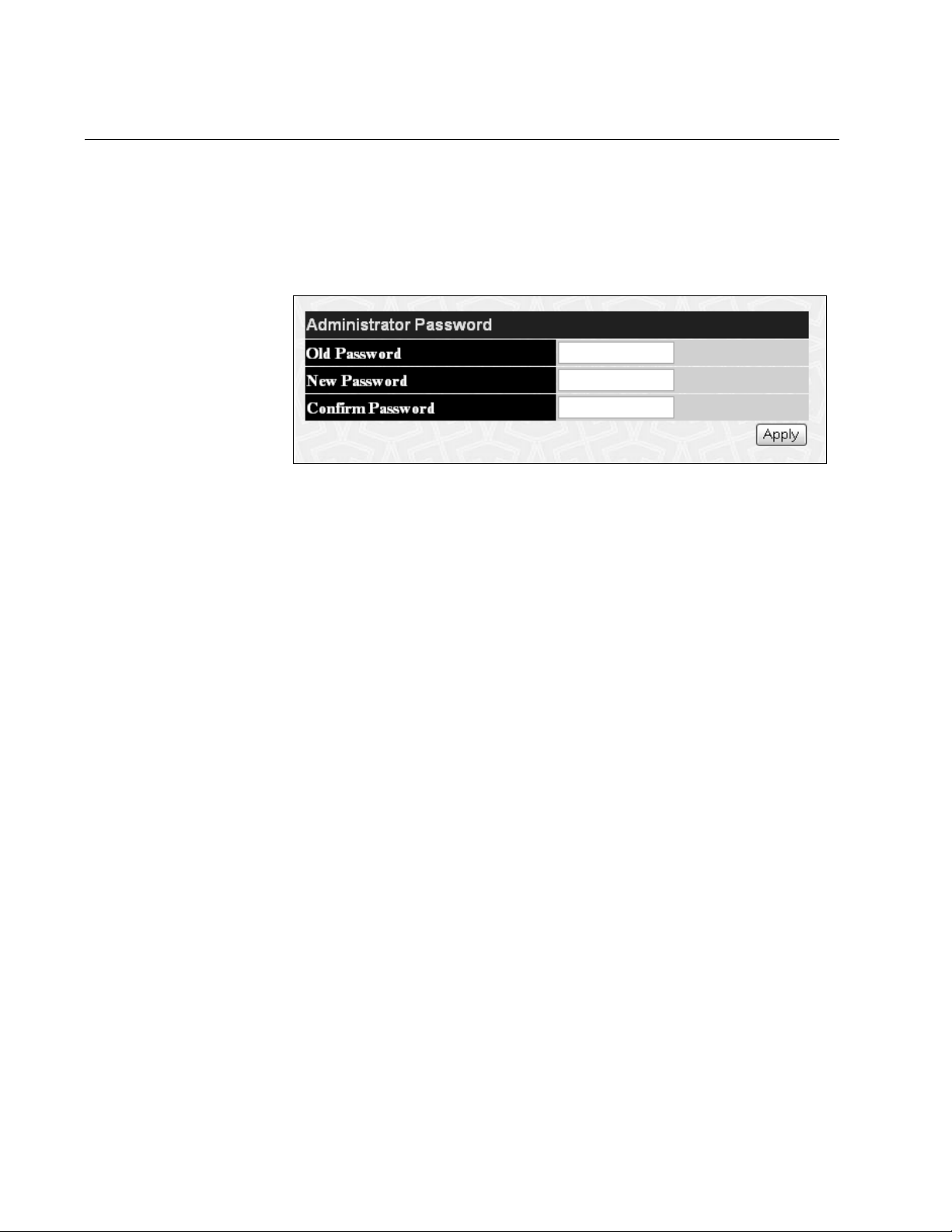
Changing the Administrator’s Password
To reset the administrator’s password, perform the following procedure:
1. From the main menu, select Administrator Password.
The Administrator Password page is shown in Figure 5.
Figure 5. Administrator Password Page
2. In the Old Password field, type the old password.
3. In the New Password field, type the new password.
4. In the Confirm Password field, retype the new password.
5. Click Apply to implement your changes.
6. To save the settings to the configuration file, from the main menu,
select Save Configuration.
The Save Configuration page is shown in Figure 3 on page 14.
7. Click Apply.
22
Page 23
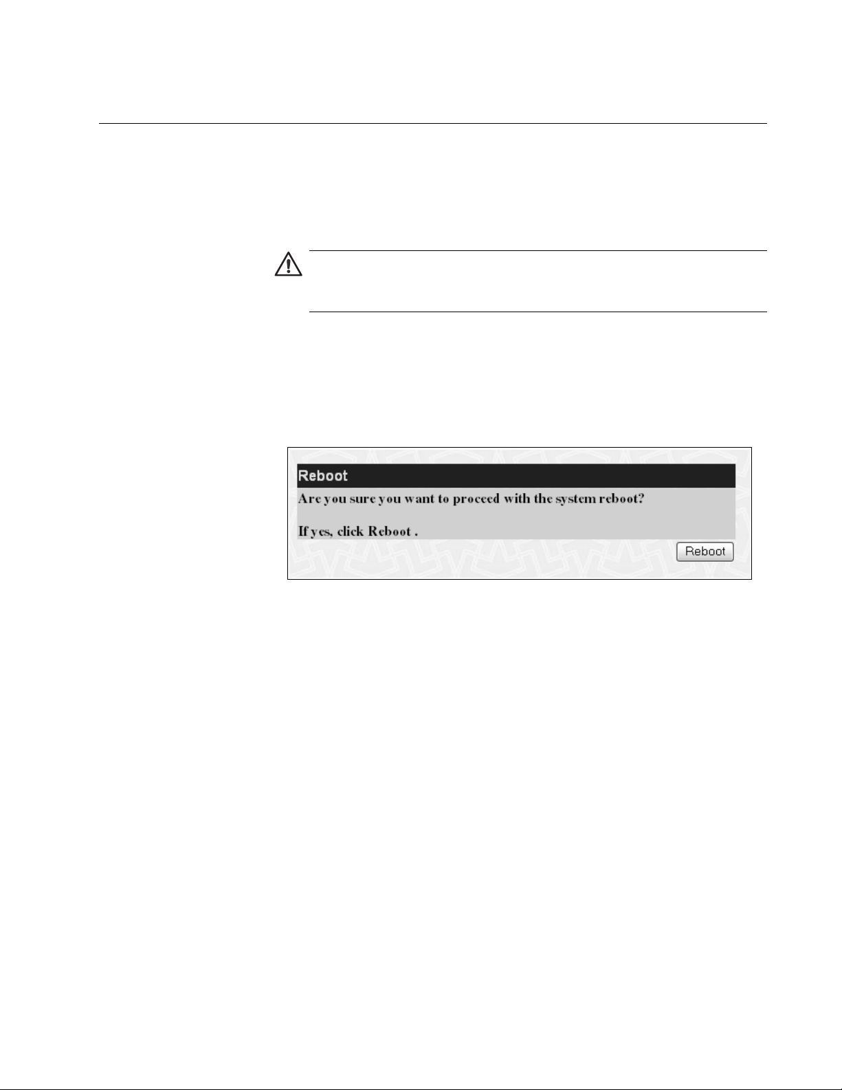
Rebooting the Switch
This procedure reboots the switch and reloads the AT-S82 management
software from flash memory. You might reboot the device if you believe it
is experiencing a problem. Rebooting the device does not change any of
the device’s parameter settings.
To reboot the switch, perform the following procedure:
1. From the main menu, select Reboot.
AT-S82 Management Software User’s Guide
Caution
The switch does not forward network traffic during the reboot
process. Some network traffic may be lost.
The Reboot page is shown in Figure 6.
Figure 6. Reboot Page
2. Click Reboot.
The switch immediately begins to reload the AT-S82 management
software. This process takes approximately one minute to complete.
You can not manage the device during the reboot. After the reboot is
finished, you can log in again if you want to continue to manage the
switch.
23
Page 24

Chapter 2: Basic Switch Parameters
Resetting the Switch and Retaining the IP Address
There are two options for resetting the switch: resetting all the parameters
except the IP address, or resetting the switch to return all the parameters
to their default values. The procedure for resetting the switch to the default
values is described in “Returning the AT-S82 Management Software to the
Factory Default Values” on page 25.
To reset the switch and retain the IP address, perform the following
procedure:
1. From the main menu, select Reset.
The Reset page is shown in Figure 6.
2. Click Apply.
The switch is reset.
Figure 7. Reset Page
24
Page 25

AT-S82 Management Software User’s Guide
Returning the AT-S82 Management Software to the Factory Default Values
This procedure returns all AT-S82 management software parameters to
their default values, including the IP address, which is reset to
192.168.1.1. To reset all the parameters except the IP address, follow the
procedure in “Resetting the Switch and Retaining the IP Address” on
page 24.
Caution
This procedure causes the switch to reboot. The switch does not
forward network traffic during the reboot process. Some network
traffic may be lost.
To return the AT-S82 management software to the default settings,
perform the following procedure:
1. From the main menu, select Reset System.
The Reset System page is shown in Figure 8.
Figure 8. Reset System Page
2. Click Apply.
The switch returns its operating parameters to the default values and
begins to reload the AT-S82 management software. This process
takes approximately one minute to complete. You cannot manage the
switch during the reboot. After the reboot is finished, you must start a
new web browser management session if you want to continue to
manage the switch.
25
Page 26

Chapter 2: Basic Switch Parameters
Downloading New Firmware
To download new firmware onto the switch, perform the following
procedure:
1. From the main menu, select Download Firmware.
The Download Firmware page is shown in Figure 9.
Figure 9. Download Firmware Page
2. In the Server IP Address field, type the IP address of the server
where the firmware file is located.
3. In the File Name field, type the path for the firmware file.
4. Click Start.
A series of download status messages, such as the one shown in
Figure 10, report the status of the download process until it is complete
and the flash memory has been updated.
26
Figure 10. Download Status Message
Page 27

Chapter 3
Port Configuration
This chapter contains the following section:
“Configuring Port Parameters” on page 28
Section I: Using the Menus Interface 27
Page 28

Chapter 3: Port Configuration
Configuring Port Parameters
This procedure explains how to configure the following port parameters:
State
Speed and duplex mode
Flow control
Medium type (only for ports 7 and 8)
To configure the ports, perform the following procedure:
1. From the main menu, select Port Configuration.
The Port Configuration page is shown in Figure 11.
28
Figure 11. Port Configuration Page
The top part of the page allows you to select port(s) and apply
configuration parameters. The bottom part shows the current
configuration.
Ports 7 and 8 are listed twice, once as a twisted pair port (copper) as
ports 7R and 8R, and once as an SFP (fiber) port as ports 7 and 8.
This allows you to see if the port is operating as a twisted pair or SFP
port, or if the ports are operating in combo fashion.
Page 29

AT-S82 Management Software User’s Guide
Note
Auto Speed/Duplex is disabled when you manually configure a
port’s Speed/Duplex. In this situation, you must use a crossover
Ethernet cable to connect that port to another network device.
2. To set the parameters for a port, choose the port using the From and
To lists. You can select one port (From 2 To 2, for example) or a range
of ports (From 1 To 5, for example).
3. From the State list, choose one of the following:
Enabled
The port is enabled. This is the default.
Disabled
The port is disabled.
4. From the Speed/Duplex list, select one of the following:
Auto - When you select this option, the switch automatically sets
the speed and duplex mode of the port. The switch determines the
highest possible common speed between the port and its end
node, and sets the port to that setting. This helps ensure that the
port and its end node are operating at the highest possible speed.
In order for a switch port to successfully autonegotiate its duplex
mode with an end node, the end node should also be using
autonegotiation. Otherwise, a duplex mode mismatch can occur. A
switch port using autonegotiation defaults to half-duplex if it detects
that the end node is not using autonegotiation. This results in a
mismatch if the end node is operating at a fixed duplex mode of
full-duplex.
To avoid this problem on the copper ports, when you connect an
end node with a fixed duplex mode of full-duplex to a switch port,
you should disable autonegotiation on the port and set the port’s
speed and duplex mode manually.
If you think that a port and end node are not operating in the same
duplex mode at a speed of 1000Mbps, you can configure the ports
for Forced mode. To do this, you configure the switch port to be the
master port (capable of sending detect and negotiate signals), and
the end node as a slave port (capable of receiving negotiate
signals).
Note
You cannot modify the speed or duplex mode of the SFP ports.
29
Page 30

Chapter 3: Port Configuration
10M/Half - 10Mbps, half duplex
10M/Full - 10Mbps, full duplex
100M/Half - 100Mbps, half duplex
100M/Full - 100Mbps, full duplex
1000M/Full - 1000Mbps, full duplex
1000M_M/Full - 1000Mbps, full duplex for port operating as a
Master port at 1000Mbps in Force mode. This allows the port to
send detect and negotiate signals.
1000M_S/Full - 1000Mbps, full duplex for port operating as a Slave
port at 1000Mbps in Force mode. This allows the port to receive
negotiate signals.
5. To enable or disable flow control on the port, choose the port using the
From and To lists. You can select one port (From 2 To 2, for example)
or a range of ports (From 1 To 5, for example).
6. From the Flow Control list, choose one of the following:
Enabled
Flow control is enabled.
Disabled
Flow control is disabled. This is the default.
7. From the Medium Type list, choose one of the following:
Note
This setting applies only to the SFP ports, ports 7 and 8, shown as
ports 7F and 8F in the Port Configuration page.
Copper
Copper SFP.
Fiber
Fiber SFP.
8. Click Apply to implement your changes.
9. To save the settings to the configuration file, from the main menu,
select Save Configuration.
30
The Save Configuration page is shown in Figure 3 on page 14.
10. Click Apply.
Page 31

Chapter 4
Trunking
This chapter contains the following sections:
“Trunking Overview” on page 32
“Configuring the Trunking Algorithm” on page 34
“Setting up the Trunk” on page 35
Section I: Using the Menus Interface 31
Page 32

Chapter 4: Trunking
Trunking Overview
A port trunk is an economical way for you to increase the bandwidth
between the Ethernet switch and another networking device, such as a
network server, router, workstation, or another Ethernet switch. A port
trunk is a group of ports that have been grouped together to function as
one logical path. A port trunk, therefore, increases the bandwidth between
the switch and the other network device and is useful in situations where a
single physical link between the devices is insufficient to handle the traffic
load. The AT-S82 management software provides for four trunks with a
maximum of two ports each.
Because network vendors employ different techniques to implement
trunking, a trunk on one device might not be compatible with the same
feature on a device from another manufacturer. Therefore, trunks are
typically made only between devices from the same vendor.
If a port in a static trunk loses its link, the trunk’s total bandwidth is
reduced until the lost link is reconfigured.
Trunking
Guidelines
The following are guidelines for setting up trunking:
To ensure compatibility, set up trunks only between AT-GS950/8
devices.
The trunk always contains two ports, one of which is designated the
master port.
The AT-S82 management software is preconfigured for you to select
trunks 1, 2, 3, or 4, with ports preassigned to each trunk. Trunk 1 has
ports 1 and 2, trunk 2 has ports 3 and 4, and so forth. You cannot alter
either setting.
Before you create a trunk, examine the speed, duplex mode, and flow
control settings of all the ports that will be in the trunk. Verify that the
port settings are identical.
After you create a trunk, do not change the speed, duplex mode, or
flow control setting of any port in the trunk without making the same
changes to the other ports.
The ports of the trunk must be members of the same VLAN.
The switch selects the lowest numbered port in the trunk to handle
broadcast packets and packets of unknown destination. For example,
in trunk 2 containing ports 3 and 4, port 3 is used for broadcast
packets.
32
Trunking
Algorithm
One of the steps in creating a trunk is the selection of a load distribution
method, also known as the trunking (or load distribution) algorithm. This
algorithm determines how the switch distributes the traffic load across the
ports of the trunk. The AT-S82 management software provides three load
Page 33

AT-S82 Management Software User’s Guide
distribution methods:
MAC-SA - source MAC address
MAC-DA - destination MAC address
DAxorSA - destination MAC address/source MAC address
33
Page 34

Chapter 4: Trunking
Configuring the Trunking Algorithm
To configure the trunk load method, perform the following procedure:
1. From the main menu, select Trunking Algorithm.
The Trunking Algorithm page is shown in Figure 12.
Figure 12. Trunking Algorithm Page
2. Choose one of the load methods from the list:
MAC-SA
By the source MAC address.
MAC-DA
By the destination MAC address.
DAxorSA
Using either the destination MAC address or source MAC address.
3. Click Apply to implement your changes.
4. To save the settings to the configuration file, from the main menu,
select Save Configuration.
The Save Configuration page is shown in Figure 3 on page 14.
5. Click Apply.
34
Page 35

Setting up the Trunk
To set up the trunk, perform the following procedure:
1. From the main menu, select Port Trunking.
AT-S82 Management Software User’s Guide
The Port Trunking page is shown in Figure 13.
Figure 13. Port Trunking Page
The current trunks, if any, are shown in the Current Trunking Group
Entries area.
2. Click Add.
The Port Trunking Configuration page is shown in Figure 14.
Figure 14. Port Trunking Configuration Page
35
Page 36

Chapter 4: Trunking
3. For the Group ID, choose a trunk group ID from the list. IDs from 1
through 4 are available. Note that when you choose a group ID that
ports are automatically selected on the Port Map. You cannot
designate any other ports for the trunk
4. For the State, choose the state of the trunk, either enabled or
disabled.
Note
Ignore the Master Port field. The Active Port field displays which
ports in the trunk have established an active link. The Flooding port
field displays the lowest active port in the trunk pair.
5. Click Apply to implement your changes.
6. To save the settings to the configuration file, from the main menu,
select Save Configuration.
The Save Configuration page is shown in Figure 3 on page 14.
7. Click Apply.
36
Page 37

Chapter 5
Port Mirroring
This chapter contains the following sections:
“Port Mirroring Overview” on page 38
“Configuring Port Mirroring” on page 39
Section I: Using the Menus Interface 37
Page 38

Chapter 5: Port Mirroring
Port Mirroring Overview
The port mirroring feature allows you to unobtrusively monitor the ingress
and egress traffic on a port on the switch by having the traffic copied to
another switch port. By connecting a network analyzer to the port where
the traffic is being copied to, you can monitor the traffic on the other port
without impacting its performance or speed.
The port whose traffic you want to mirror is called the mirrored port. The
port where the traffic will be copied to is called the mirroring or target port.
Observe the following guidelines when using this feature:
You can configure only one target port at a time.
The mirrored and mirroring ports must be on the same switch.
This feature copies both the ingress and egress traffic of the mirrored
port.
The mirroring port (target port) cannot be used for normal Ethernet
switching and cannot be part of a trunk.
38
Page 39

Configuring Port Mirroring
To configure the trunk load method, perform the following procedure:
1. From the main menu, select Port Mirroring.
The Port Mirroring page is shown in Figure 15.
AT-S82 Management Software User’s Guide
Figure 15. Port Mirroring Page
2. From the Target Port list, select the target port.
This is the port where you will connect the network analyzer and the
port to which traffic will be mirrored.
3. From the Status list, choose Enabled.
4. In the table, choose one of the following options for the mirrored
(source )port:
RX - Mirrors only received traffic.
TX - Mirrors only transmitted traffic.
Both - Mirrors both received and transmitted traffic.
5. Click Apply to implement your changes.
6. To save the settings to the configuration file, from the main menu,
select Save Configuration.
The Save Configuration page is shown in Figure 3 on page 14.
7. Click Apply.
39
Page 40

Chapter 5: Port Mirroring
40
Page 41

Chapter 6
VLANs
This chapter contains the following sections:
“VLAN Features” on page 42
“VLAN Overview” on page 44
“Working with VLANs” on page 47
“Protected Ports VLAN” on page 50
Section I: Using the Menus Interface 41
Page 42

Chapter 6: VLANs
VLAN Features
A Virtual Local Area Network (VLAN) is a logical grouping of devices on
different physical LAN segments that allows users to communicate as if
they were physically connected to a single LAN, independent of the
physical configuration of the network.
With VLANs, you can segment your network and group end-nodes with
related functions into their own separate, logical LAN segments. For
example, the marketing personnel in your company may be spread
throughout a building. Assigning marketing to a single VLAN allows
marketing personnel to share resources and bandwidth as if they were
connected to the same segment. The resources of other departments can
be visible to the marketing VLAN members, accessible, or accessible only
to specified individuals.
A few benefits of a VLAN architecture are described in the following
sections.
Increased
Performance
Improved
Manageability
Increased
Security
In traditional Layer 2 switched networks, broadcast packets are sent to
each and every individual port. Grouping users into logical networks limits
broadcast traffic to users performing similar functions or users within
individual workgroups. High traffic, the danger of broadcast storms, router
latency, and data collisions are significantly reduced, and the efficiency of
the entire network is improved.
VLANs provide a fundamental improvement in the design, administration,
and management of LANs. Before VLANs, physical changes to a network
were made at the switch in the wiring closet.
For example, if an employee transferred to a new department, changing
that employee’s LAN segment assignment often required a physical wiring
change at the switch.
As a software-base solution, VLANs eliminate the restriction of existing
network design and cabling infrastructure and allow the centralized
configuration of switches located in many different locations. VLAN
memberships are changed quickly and efficiently from the management
console rather than in a wiring closet.
VLANs provide additional security not available in a shared media network
environment. Because a switched network only delivers frames to
intended recipients, and only broadcast frames to other members of the
VLAN, a network administrator can segment users requiring access to
sensitive information into separate VLANs from the rest of the general
user community.
42
Page 43

AT-S82 Management Software User’s Guide
VLANs can be used to control the flow of data in your network, since the
traffic generated by an end-node in a VLAN is restricted to the other endnodes in the same VLAN. In addition, VLANs can prevent data from
flowing to unauthorized end-nodes
43
Page 44

Chapter 6: VLANs
VLAN Overview
This VLAN overview contains the following sections:
“VLAN Name,” next
“VLAN Identifier” on page 44
“VLAN Port Members” on page 44
“Incoming and Outgoing Tagged and Untagged Frames” on page 45
“Guidelines for Creating a VLAN” on page 46
VLAN Name To create a port-based VLAN, you must give it a name. The name should
reflect the function of the network devices that are be members of the
VLAN. Examples include Sales, Production, and Engineering.
VLAN Identifier Every VLAN in a network must have a unique number assigned to it. This
number is called the VLAN identifier (VID). This number uniquely identifies
a VLAN in the switch and the network. The factory default VID is 1 for all
ports.
VLAN Port
Members
If a VLAN consists only of ports located on one physical switch in your
network, you assign it a VID different from all other VLANs in your
network.
If a VLAN spans multiple switches, then the VID for the VLAN on the
different switches should be the same. The switches are then able to
recognize and forward frames belonging to the same VLAN even though
the VLAN spans multiple switches.
For example, if you had a VLAN titled Marketing that spanned three
AT-GS950/8 switches, you would assign the Marketing VLAN on each
switch the same VID.
You need to specify which ports on the switch are to be members of a
VLAN. A port can be specified as a member of one or more VLANs up to
255, the maximum number of VLANs supported by the switch. The factory
default VID is 1. Therefore, each port is initially configured to be a member
of VLAN 1, which is known as the default VLAN.
Note
The switch is preconfigured with the Default VLAN only. All ports on
the switch are initially members of the Default VLAN.
44
If a port is assigned to be a new member of a VLAN, its membership can
be defined as either tagged or untagged.
Page 45

AT-S82 Management Software User’s Guide
Tagged Port Members
A port is a tagged member of a specific VLAN when it is a member of more
than one VLAN. If a port is a tagged member of one VLAN, then the same
port is also an untagged member of another VLAN.
Untagged Port Members
A port is an untagged member of a VLAN if the PVID is equal to the VID of
that VLAN. A port can be an untagged member of only one VLAN. An
example of this is the Default VLAN configuration where all ports are
initially configured to be untagged members of VLAN 1 only. A port can
also be an untagged member of one VLAN and be a tagged member of
one or more VLANS.
Incoming and
Outgoing Tagged
and Untagged
Frames
The VLAN information within an Ethernet frame is referred to as a tag or
tagged header. The frame containing this VLAN tag information is referred
to as a tagged frame. Likewise, a frame that does not contain this VLAN
tag information is referred to as an untagged or standard frame. A tag,
which follows the source and destination addresses in the frame’s header,
contains the VID information of the VLAN to which the frame belongs,
according to the IEEE802.3ac VLAN tagging standard.
When a switch receives a frame, it examines the frame header to see if it
contains a VLAN tag (tagged frame) or no tag (untagged frame). After
switching the frame to an outgoing port and before transmitting it, the
switch determines if the tag information should be kept in the header or
should be stripped out and made into an untagged frame.
Incoming Frames
Tagged frames received by the switch are only accepted (not dropped) if
the tag information contained in the frame is equal to one of the VIDs of
which the port is a member. If the tag information contained in the frame
does not match one of these VIDs, the frames are dropped or discarded.
Untagged frames received by the switch are always accepted by all ports
on the switch. Each untagged frame is assigned to the VLAN number of
which the port is an untagged member. The switch then forwards this
frame to one of the other member ports of that VLAN.
Outgoing Frames
Frames being transmitted from the switch retain their VLAN tag
information in the frame header if the frame’s tag does not match the PVID
of the port (a tagged member of that VLAN). These frames are untagged
after transmission from the switch.
The VLAN tag information in the header of the frame is stripped from the
frame’s header if the tag matches the PVID of the port (an untagged
45
Page 46

Chapter 6: VLANs
member of the VLAN). These frames are untagged after transmission from
the switch.
Guidelines for
Creating a VLAN
The following are guidelines for creating a VLAN.
Each VLAN must be assigned a unique VID. If a particular VLAN
spans multiples switches, each part of the VLAN on the different
switches should be assigned the same VID.
A port can be an untagged member of only one VLAN at a time and
can receive both tagged and untagged packets.
If you want a port to be an untagged member of a different VLAN, you
must first modify the VLAN (usually the default VLAN) where the port
is an untagged member. First, delete that port from the original VLAN
and then assign the port to another VLAN as an untagged port.
A VLAN that spans multiple switches requires a port on each switch
where the VLAN is located to function as an interconnection between
the switches where the various parts of the VLAN reside.
This port may be defined as an untagged member of a VLAN where
the port is connected to another switch via another untagged port
member of the VLAN. This means that all traffic on this inter-switch
port contains traffic for that VLAN only.
Another scenario is where the port could be an untagged member of
one VLAN and a tagged member of one or more VLANs. The port
would then be connected to another switch via a port with the same
VLAN membership. This means that the traffic on this inter-switch port
is for any or all of the VLANs of which the port is a member.
46
If there are end nodes in different VLANs that need to communicate
with each other, a router or Layer 3 switch is required to interconnect
the VLANs.
The switch can support up to a total of 255 VLANs.
Page 47

AT-S82 Management Software User’s Guide
Working with VLANs
This section contains the following procedures for working with VLANs:
“Creating a VLAN,” next
“Displaying all VLANs” on page 48
“Modifying a VLAN” on page 49
Creating a VLAN To create a VLAN, perform the following procedure:
1. From the main menu, select Static VLANs.
The 802.1Q Static VLAN page is shown in Figure 16.
Figure 16. 802.1Q Static VLAN Page
2. Click Add.
A new page opens where you specify the VLAN, as shown in
Figure 17.
Figure 17. VLAN Detail Page
47
Page 48

Chapter 6: VLANs
3. In the VID field, supply a number for the VLAN ID, from 2 to 4094.
4. In the VLAN Name field, enter a unique name for the VLAN. No
spaces are allowed.
5. In the Tag row, select the ports that you want to be tagged members of
the VLAN.
Note
If you want a port to be an untagged member of a different VLAN,
you must first modify the VLAN (usually the default VLAN) where the
port is an untagged member. First, delete that port from the original
VLAN and then assign the port to another VLAN as an untagged
port.
6. To select the ports you want to assign to the VLAN, do one of the
following:
In the None row, click the port that you do not want to be included
in the VLAN.
Displaying all
VLANs
In the VLAN Member row, select the ports that you want to assign
to the VLAN.
7. Click Apply to implement your changes.
8. To save the settings to the configuration file, from the main menu,
select Save Configuration.
The Save Configuration page is shown in Figure 3 on page 14.
9. Click Apply.
To view all the currently configured VLANs, perform the following
procedure:
1. From the main menu, select VLAN Configuration.
The VLAN Configuration page is shown in Figure 16 on page 47.
2. Click Show All Static VLAN Entries.
48
Page 49

AT-S82 Management Software User’s Guide
The list of current VLANs is shown in Figure 18.
Figure 18. Current VLANs Page
Modifying a
VLAN
To modify the ports in a VLAN, perform the following procedure:
1. From the main menu, select VLAN Configuration.
The VLAN Configuration page is shown in Figure 16 on page 47.
2. Click Modify next to the VLAN you want to modify.
The VLAN detail page for that VLAN is displayed, as shown in Figure
17 on page 47.
3. Make your changes to the VLAN.
4. Click Apply to implement your changes.
5. To save the settings to the configuration file, from the main menu,
select Save Configuration.
The Save Configuration page is shown in Figure 3 on page 14.
6. Click Apply.
Deleting a VLAN To delete a VLAN, perform the following procedure:
1. From the main menu, select VLAN Configuration.
The VLAN Configuration page is shown in Figure 16 on page 47.
2. Click the X in the Delete column next to the VLAN you want to delete.
The VLAN is immediately deleted.
49
Page 50

Chapter 6: VLANs
Protected Ports VLAN
You use the protected ports VLAN feature when you want to prevent ports
from communicating with one another, but you want them all to have
access to common resources. For example, in a hotel or apartment
complex, the computer in each room or apartment needs to be isolated
from one another, but they all need access to the internet or a server. This
feature is called traffic segmentation. You set up traffic segmentation by
selecting the ports connected to each room or apartment and identifying
them as isolated ports, and then connecting one port to the WAN.
In Figure 19, the connection to the WAN is assigned to fiber port 8. This
port is configured as the Primary (Ingress) port for the switch. Because it is
the Primary port, it has full duplex capability to communicate with ports 17R. Ports 1-7R are configured to be isolated from one another, and
therefore cannot communicate with one another.
912
WAN
Figure 19. Protected Ports VLAN Example
Figure 20 shows what the Protected Port page for Figure 19 looks like.
Figure 20. Protected Port Page for Figure 19
50
To set up a protected ports VLAN, perform the following procedure:
Page 51

AT-S82 Management Software User’s Guide
1. From the main menu, select Protected Port.
The Protected Port page is shown in Figure 21.
Figure 21. Protected Port Page
2. Determine which port(s) will be the Primary port(s).
3. Click the box on the Isolated row for all ports that you want to isolate
from one another.
The box for the Primary port(s) should be empty.
4. Click Apply.
51
Page 52

Chapter 6: VLANs
52
Page 53

Chapter 7
Class of Service
This chapter contains the following sections:
“Class of Service Overview” on page 54
“Mapping Priorities to Queues” on page 57
“Setting Up the Schedule” on page 58
Section I: Using the Menus Interface 53
Page 54

Chapter 7: Class of Service
Class of Service Overview
When the egress queues on a port in an Ethernet switch contains more
packets than the port can handle in a timely manner, the port may be
forced to delay the transmission of some packets. A port may be forced to
delay transmission of packets while it handles other traffic and, in some
situations, some packets destined to be forwarded from the port are
discarded.
Minor delays are often of no consequence to a network or its performance.
But there are applications referred to as delay- or time-sensitive, that can
be impacted by packet delays. Voice transmission and video conferencing
are two examples. If packets containing data for either of these
applications are delayed in reaching their destination, the audio or video
quality may suffer.
CoS allows you to manage the flow of traffic through a switch by setting
the switch ports to give higher priority to some packets, such as delaysensitive traffic, over other packets. This is referred to as prioritizing traffic.
Mapping Ports to
Egress Queues
CoS applies primarily to tagged packets. A tagged packet contains
information that specifies the VLAN to which the packet belongs and can
also contain a priority level. Network switches and other networking
devices use the priority level to determine how important that packet is
compared to other packets. High priority packets are handled before low
priority packets.
CoS, as defined in the IEEE 802.1p standard, has eight levels of priority—
0 to 7, with 0 the lowest priority and 7 the highest. Each port has four
egress queues, labeled Q0, Q1, Q2, and Q3. Q0 is the lowest priority
queue and Q3 is the highest. A packet in a high priority egress queue is
typically transmitted out a port sooner than a packet in a low priority
queue.
54
Page 55

AT-S82 Management Software User’s Guide
Table 1 lists the mappings between the eight CoS priority levels and the
four egress queues of a switch port.
Table 1. Default Mappings of IEEE 802.1p Priority Levels to Priority
Queues
IEEE 802.1p Priority Level Port Priority Queue
0Q1
1Q0
2Q0
3Q1
4Q2
5Q2
6Q3
7Q3
For example, if a tagged packet with a priority level of 2 entered a port on
the switch, the switch would store the packet in Q11 on the egress port.
Note that priority 0 is mapped to CoS queue 1 instead of CoS queue 0
because tagged traffic that has never been prioritized has a VLAN tag user
priority of 0. If priority 0 was mapped to CoS queue 0, this default traffic
goes to the lowest queue, which is probably undesirable.
Scheduling A switch port needs a mechanism for knowing the order in which it should
handle the packets in its four egress queues. For example, if all the
queues contain packets, should the port transmit all packets from Q3, the
highest priority queue, before moving on to the other queues? Or, should it
instead just send a few packets from each queue and, if so, how many?
This control mechanism is called scheduling. Scheduling determines the
order in which a port handles the packets in its egress queues. The
AT-S82 management software uses weighted round-robin scheduling.
This method functions as its name implies. The port transmits a set
number of packets from each queue, in a round robin fashion, so that each
queue has an opportunity to transmit traffic. This method guarantees that
every queue receives some attention from the port for transmitting
packets.
To set up scheduling, you need to specify the maximum number of
packets a port should transmit from a queue before moving to the next
queue. This is referred to as specifying the weight of a queue. In all
likelihood, you will want to give greater weight to the packets in the higher
priority queues over the lower queues. Table 2 provides a scheduling
55
Page 56

Chapter 7: Class of Service
example.
Table 2. Scheduling Example
Port Egress Queue
Maximum Number of
Packets
Q0 1
Q1 5
Q2 15
Q3 25
In this example, the port transmits a maximum of 25 packets from Q3,
then 15 packets from Q2, and so forth.
56
Page 57

Mapping Priorities to Queues
To map priorities to queues, perform the following procedure:
1. From the main menu, select CoS Priority to Queue.
The CoS Priority to Queue page is shown in Figure 22.
AT-S82 Management Software User’s Guide
Figure 22. CoS Priority to Queue Page
The default queue for each priority is displayed
2. To set the queue associated with a priority, select a new queue from
the adjacent list.
3. Click Apply to implement your changes.
4. To save the settings to the configuration file, from the main menu,
select Save Configuration.
The Save Configuration page is shown in Figure 3 on page 14.
5. Click Apply.
57
Page 58

Chapter 7: Class of Service
Setting Up the Schedule
To configure map ports to priority queues, perform the following
procedure:
1. From the main menu, select CoS Output Scheduling.
The CoS Output Scheduling page is shown in Figure 22.
Figure 23. Output Scheduling Page
2. To set the weight for a queue, go to that queue and type a number.
3. Click Apply to implement your changes.
4. To save the settings to the configuration file, from the main menu,
select Save Configuration.
The Save Configuration page is shown in Figure 3 on page 14.
5. Click Apply.
58
Page 59

Assigning Priority to Ports
To assign a priority to a specific port, perform the following procedure:
1. From the main menu, select CoS Port Priority Assignment.
The CoS Port Priority Assignment page is shown in Figure 24.
AT-S82 Management Software User’s Guide
Figure 24. CoS Port Priority Assignment Page
2. Choose the port you want to set using the From and To lists. You can
select one port (From 2 To 2, for example) or a range of ports (From 1
To 5, for example).
3. To set the priority of the port, choose a priority from the Priority list.
4. Click Apply to implement your changes.
5. To save the settings to the configuration file, from the main menu,
select Save Configuration.
The Save Configuration page is shown in Figure 3 on page 14.
6. Click Apply.
59
Page 60

Chapter 7: Class of Service
60
Page 61

Chapter 8
Spanning Tree Protocol (STP)
This chapter contains the following sections:
“Spanning Tree Overview” on page 62
“Configuring Spanning Tree” on page 71
“Configuring STP Port Settings” on page 74
Section I: Using the Menus Interface 61
Page 62

Chapter 8: Spanning Tree Protocol (STP)
Spanning Tree Overview
The performance of a Ethernet network can be negatively impacted by the
formation of a data loop in the network topology. A data loop exists when
two or more nodes on a network can transmit data to each other over
more than one data path. The problem that data loops pose is that data
packets can become caught in repeating cycles, referred to as broadcast
storms, that needlessly consume network bandwidth and can significantly
reduce network performance.
The Spanning Tree Protocol (STP) prevents data loops from forming by
ensuring that only one path exists between the end nodes in your network.
Where multiple paths exist, these protocols place the extra paths in a
standby or blocking mode, leaving only one main active path.
STP can also activate a redundant path if the main path goes down. So
not only do these protocols guard against multiple links between segments
and the risk of broadcast storms, but they can also maintain network
connectivity by activating a backup redundant path in case a main link
fails.
Bridge Priority
and the Root
Bridge
Where the two protocols differ is in the time each takes to complete the
process referred to as convergence. When a change is made to the
network topology, such as the addition of a new bridge, a spanning tree
protocol must determine whether there are redundant paths that must be
blocked to prevent data loops, or activated to maintain communications
between the various network segments. This is the process of
convergence.
With STP, convergence can take up to a minute to complete in a large
network. This can result in the loss of communication between various
parts of the network during the convergence process, and the subsequent
lost of data packets.
The STP implementation on the AT-S82 management software complies
with the IEEE 802.1d standard.
The first task that bridges perform when a spanning tree protocol is
activated on a network is the selection of a root bridge. A root bridge
distributes network topology information to the other network bridges and
is used by the other bridges to determine if there are redundant paths in
the network.
A root bridge is selected by the bridge priority number, also referred to as
the bridge identifier, and sometimes the bridge’s MAC address. The bridge
with the lowest bridge priority number in the network is selected as the
root bridge. If two or more bridges have the same bridge priority number,
of those bridges the one with the lowest MAC address is designated as
the root bridge.
62
Page 63

AT-S82 Management Software User’s Guide
You can change the bridge priority number in the AT-S82 management
software. You can designate which switch on your network you want as
the root bridge by giving it the lowest bridge priority number. You might
also consider which bridge should function as the backup root bridge in the
event you need to take the primary root bridge offline, and assign that
bridge the second lowest bridge identifier number.
The bridge priority has a range 0 to 61440 in increments of 4096. To make
this easier for you, the AT-S82 management software divides the range
into increments. The valid range is of sixteen increments is shown in
Table 3.
Table 3. Bridge Priority Value Increments
Increment
Bridge
Priority
Increment
Bridge
Priority
0 0 8 32768
1 4096 9 36864
2 8192 10 40960
3 12288 11 45056
4 16384 12 49152
5 20480 13 53248
6 24576 14 57344
7 28672 15 61440
Path Costs and Port Costs
After the root bridge has been selected, the bridges must determine if the
network contains redundant paths and, if one is found, they must select a
preferred path while placing the redundant paths in a backup or blocking
state.
Where there is only one path between a bridge and the root bridge, the
bridge is referred to as the designated bridge and the port through which
the bridge is communicating with the root bridge is referred to as the root
port.
If redundant paths exist, the bridges that are a part of the paths must
determine which path will be the primary, active path, and which path(s)
will be placed in the standby, blocking mode. This is accomplished by an
determination of path costs. The path offering the lowest cost to the root
bridge becomes the primary path and all other redundant paths are placed
into blocking state.
Path cost is determined through an evaluation of port costs. Every port on
63
Page 64

Chapter 8: Spanning Tree Protocol (STP)
a bridge participating in STP has a cost associated with it. The cost of a
port on a bridge is typically based on port speed. The faster the port, the
lower the port cost. The exception to this is the ports on the root bridge,
where all ports have a port cost of 0.
Path cost is simply the sum of the port costs between a bridge and the root
bridge.
The AT-GS950/8 WebSmart switch automatically sets the port cost
according to the speed of the port, assigning a lower value for higher
speeds. Table 6 lists the STP port costs.
Table 4. STP Port Costs
Port Speed Port Cost
10 Mbps 100
100 Mbps 10
1000 Mbps 4
Table 5 lists the STP port costs with Auto when a port is part of a port
trunk.
Table 5. STP Auto-Detect Port Trunk Costs
Port Speed Port Cost
10 Mbps 4
100 Mbps 4
1000 Mbps 2
Table 6 lists the RSTP port costs with Auto.
Table 6. RSTP Auto Port Costs
Port Speed Port Cost
10 Mbps 2,000,000
100 Mbps 200,000
1000 Mbps 20,000
64
Table 7 lists the RSTP port costs with Auto when the port is part of a port
Page 65

AT-S82 Management Software User’s Guide
trunk.
Table 7. RSTP Auto Port Trunk Costs
Port Speed Port Cost
10 Mbps 20,000
100 Mbps 20,000
1000 Mbps 2,000
You cannot set the port cost manually.
Port Priority
If two paths have the same port cost, the bridges must select a preferred
path. In some instances this can involve the use of the port priority
parameter. This parameter is used as a tie breaker when two paths have
the same cost.
The range for port priority is 0 to 240. As with bridge priority, this range is
broken into increments, in this case multiples of 16. Table 8 lists the valid
port priority values. The default value is 128, which is increment 8.
Table 8. Port Priority Value Increments
Increment
Port
Priority
Increment
Port
Priority
008128
1 16 9 144
2 3210160
3 48 11 176
4 6412192
5 8013208
6 9614224
7 112 15 240
Forwarding Delay and Topology Changes
If there is a change in the network topology due to a failure, removal, or
addition of any active components, the active topology also changes. This
may trigger a change in the state of some blocked ports. However, a
change in a port state is not activated immediately.
It might take time for the root bridge to notify all bridges that a topology
65
Page 66

Chapter 8: Spanning Tree Protocol (STP)
change has occurred, especially if it is a large network. If a topology
change is made before all bridges have been notified, a temporary data
loop could occur, and that could adversely impact network performance.
To forestall the formation of temporary data loops during topology
changes, a port designated to change from blocking to forwarding passes
through two additional states—listening and learning—before it begins to
forward frames. The amount of time a port spends in these states is set by
the forwarding delay value. This value states the amount of time that a
port spends in the listening and learning states prior to changing to the
forwarding state.
The forwarding delay value is adjustable in the AT-S82 management
software. The appropriate value for this parameter depends on a number
of variables; the size of your network is a primary factor. For large
networks, you should specify a value large enough to allow the root bridge
sufficient time to propagate a topology change throughout the entire
network. For small networks, you should not specify a value so large that a
topology change is unnecessarily delayed, which could result in the delay
or loss of some data packets.
Note
The forwarding delay parameter applies only to ports on the switch
that are operating STP-compatible mode.
Hello Time and Bridge Protocol Data Units (BPDUs)
The bridges that are part of a spanning tree domain communicate with
each other using a bridge broadcast frame that contains a special section
devoted to carrying STP or RSTP information. This portion of the frame is
referred to as the bridge protocol data unit (BPDU). When a bridge is
brought online, it issues a BPDU in order to determine whether a root
bridge has already been selected on the network, and if not, whether it has
the lowest bridge priority number of all the bridges and should therefore
become the root bridge.
The root bridge periodically transmits a BPDU to determine whether there
have been any changes to the network topology and to inform other
bridges of topology changes. The frequency with which the root bridge
sends out a BPDU is called the hello time. This is a value that you can set
in the AT-S82 management software. The interval is measured in seconds
and the default is two seconds. Consequently, if an AT-GS950/8
WebSmart switch is selected as the root bridge of a spanning tree domain,
it transmits a BPDU every two seconds.
66
Page 67

AT-S82 Management Software User’s Guide
Point-to-Point and Edge Ports
Note
This section applies only to RSTP.
Part of the task of configuring RSTP is defining the port types on the
bridge. This relates to the device(s) connected to the port. With the port
types defined, RSTP can reconfigure a network much quicker than STP
when a change in network topology is detected.
There are two possible selections:
Point-to-point port
Edge port
If a bridge port is operating in full-duplex mode, than the port is functioning
as a point-to-point port. Figure 25 illustrates two AT-GS950/8 WebSmart
switches that have been connected with one data link. With the link
operating in full-duplex, the ports are point-to-point ports.
912
Point-to-Point Ports
(Full-duplex Mode)
912
Figure 25. Point-to-Point Ports
If a port is operating in half-duplex mode and is not connected to any
further bridges participating in STP or RSTP, then the port is an edge port.
Figure 26 illustrates an edge port on an AT-GS950/8 WebSmart switch.
The port is connected to an Ethernet hub, which in turn is connected to a
series of Ethernet workstations. This is an edge port because it is
connected to a device operating at half-duplex mode and there are no
participating STP or RSTP devices connected to it.
67
Page 68

Chapter 8: Spanning Tree Protocol (STP)
912
Edge Port
Figure 26. Edge Port
A port can be both a point-to-point and an edge port at the same time. It
operates in full-duplex and has no STP or RSTP devices connected to it.
Figure 27 illustrates a port functioning as both a point-to-point and edge
port.
912
Point-to-Point and Edge Port
Workstation
(Full-duplex Mode)
Figure 27. Point-to-Point and Edge Port
Determining whether a bridge port is point-to-point, edge, or both, can be
a bit confusing. For that reason, do not change the default values for this
RSTP feature unless you have a good grasp of the concept. In most
cases, the default values work well.
68
RSTP IEEE 802.1w is fully compliant with STP IEEE 802.1d. Your network
can consist of bridges running both protocols. STP and RSTP in the same
network can operate together to create a single spanning tree domain.
Page 69

AT-S82 Management Software User’s Guide
If you decide to activate spanning tree on the switch, there is no reason
not to activate RSTP on an AT-GS950/8 WebSmart switch even when all
other switches are running STP. The switch can combine its RSTP with
the STP of the other switches. The switch monitors the traffic on each port
for BPDU packets. Ports that receive RSTP BPDU packets operates in
RSTP mode while ports receiving STP BPDU packets operate in STP
mode.
Spanning Tree
and VLANs
The spanning tree implementation in the AT-S82 management software is
a single-instance spanning tree. The switch supports just one spanning
tree. You cannot define multiple spanning trees.
The single spanning tree encompasses all ports on the switch. If the ports
are divided into different VLANs, the spanning tree crosses the VLAN
boundaries. This point can pose a problem in networks containing multiple
VLANs that span different switches and are connected with untagged
ports. In this situation, STP blocks a data link because it detects a data
loop. This can cause fragmentation of your VLANs.
This issue is illustrated in Figure 28. Two VLANs, Sales and Production,
span two AT-GS950/8 WebSmart switches. Two links consisting of
untagged ports connect the separate parts of each VLAN. If STP or RSTP
is activated on the switches, one of the links is disabled. In the example,
the port on the top switch that links the two parts of the Production VLAN is
changed to the block state. This leaves the two parts of the Production
VLAN unable to communicate with each other.
Sales
VLAN
Production
VLAN
Blocked Port
912
912
Sales
VLAN
Blocked Data Link
Production
VLAN
Figure 28. VLAN Fragmentation
You can avoid this problem by not activating spanning tree or by
connecting VLANs using tagged instead of untagged ports. (For
69
Page 70

Chapter 8: Spanning Tree Protocol (STP)
information on tagged and untagged ports, refer to Chapter 6, “VLANs” on
page 41.)
70
Page 71

Configuring Spanning Tree
To define the spanning tree settings at the switch level, perform the
following procedure:
1. From the main menu, select STP Global Settings.
The Switch Spanning Tree Settings page is shown in Figure 29.
AT-S82 Management Software User’s Guide
Figure 29. Switch Spanning Tree Settings Page
2. From the STP Version list, select STP or RSTP.
3. In the Bridge Max Age field, enter a number for the length of time after
which stored bridge protocol data units (BPDUs) are deleted by the
bridge. All bridges in a bridged LAN use this aging time to test the age
of stored configuration messages called bridge protocol data units
(BPDUs). For example, if you use the default value 20, all bridges
delete current configuration messages after 20 seconds. This
parameter can be from 6 to 40 seconds.
71
Page 72

Chapter 8: Spanning Tree Protocol (STP)
4. In the Bridge Hello Time field, enter a number for the time interval
5. In the Bridge Forward Delay field, enter a number for the waiting
When you select a value for maximum age, observe the following
rules:
MaxAge must be greater than (2 x (HelloTime + 1)).
MaxAge must be less than (2 x (ForwardingDelay - 1)).
Note
The aging time for BPDUs is different from the aging time used by
the MAC address table.
between generating and sending configuration messages by the
bridge. This parameter can be from 1 to 10 seconds. The default is 2
seconds.
period in seconds before a bridge changes to a new state, for
example, becomes the new root bridge after the topology changes. If
the bridge transitions too soon, not all links may have yet adapted to
the change, resulting in network loops. The range is 4 to 30 seconds.
The default is 15 seconds.
6. In the Bridge Priority field, enter a number for the priority number for
the bridge. This number is used to determine the root bridge for RSTP.
The bridge with the lowest priority number is selected as the root
bridge. If two or more bridges have the same priority value, the bridge
with the numerically lowest MAC address becomes the root bridge.
When a root bridge goes offline, the bridge with the next priority
number automatically takes over as the root bridge. This parameter
can be from 0 (zero) to 61,440 in increments of 4096, with 0 being the
highest priority. For a list of the increments, refer to Table 3, “Bridge
Priority Value Increments” on page 63.
7. From the STP Version list, select one of the following:
RSTP
Enables the Remote Spanning Tree Protocol.
STP Compatible
Enables the Spanning Tree Protocol.
8. In the TX Hold Count field, enter a number from 1 to 10 to specify the
maximum number of BPDU packets in each hello time.
9. From the Forwarding BPDU list, select one of the following:
72
Enabled
The AT-GS950/8 WebSmart switch does not process the BPDU
Page 73

AT-S82 Management Software User’s Guide
packets but forwards them to adjacent switches. This is the default
setting.
Disabled
The switch processes the BPDU packets. Allied Telesis recommends
that you choose this setting.
10. Click Apply.
To configure the ports, refer to “Configuring STP Port Settings,” next.
11. To save the settings to the configuration file, from the main menu,
select Save Configuration.
The Save Configuration page is shown in Figure 3 on page 14.
12. Click Apply.
73
Page 74

Chapter 8: Spanning Tree Protocol (STP)
Configuring STP Port Settings
To configure the STP settings, perform the following procedure:
1. From the main menu, select STP Port Settings.
The STP Port Settings page is shown in Figure 30.
Figure 30. STP Port Settings Page
2. From the From and To lists, select the port(s) you want to configure,
or scroll through the list below.
3. From the State list, select one of the following:
Enabled
Enables the port for spanning tree. This is the default.
Disabled
Disables spanning tree on the port.
4. In the Cost box, type a number for the cost or type 0 for Auto
(automatic).
The spanning tree algorithm uses the cost parameter to decide which
port provides the lowest cost path to the root bridge for that LAN. The
range is 0 to 65,535. The default setting is Auto, which sets port cost
depending on the speed of the port. The Auto default values are
shown in Table 4 on page 64 andTable 5 on page 64.
5. In the Priority box, type a number for the port’s priority.
74
Page 75

AT-S82 Management Software User’s Guide
This parameter is used as a tie breaker when two or more ports are
determined to have equal costs to the root bridge. The range is 0 to
240 in increments of 16. The default value is 8 (priority value 128). For
a list of the increments, refer to Table 8, “Port Priority Value
Increments” on page 65.
6. From the Migration list, select one of the following:
No
Disallows resetting an RSTP port to handle STP BPDUs. This is the
default setting.
Yes
Resets an RSTP port, allowing it to send RSTP BPDUs. When an
RSTP bridge receives STP BPDUs on an RSTP port, the port
transmits STP BPDUs. The RSTP port continues to transmit STP
BPDUs indefinitely
7. From the Edge list, select one of the following:
False
The port does not function as an edge port.
True
Makes the port an edge port.
Note
A port can be both a point-to-point and an edge port at the same
time
8. In the P2P list, select one of the following:
Auto
The switch automatically detects if the port is functioning as a point-topoint port.
False
Sets the port to never function as a point-to-point port.
True
Sets the port to always function as a point-to-point port.
9. Click Apply.
10. To save the settings to the configuration file, from the main menu,
select Save Configuration.
The Save Configuration page is shown in Figure 3 on page 14.
11. Click Apply.
75
Page 76

Chapter 8: Spanning Tree Protocol (STP)
76
 Loading...