

Page 1
BETRIEBSANLEITUNG
MOTORHACKEN
7505 VR
7505 V2R
DE
EN
FR
IT
DA
SV
RU
PL
HU
441582_a 02 | 2016
Page 2

D
Inhaltsverzeichnis
D Betriebsanleitung...................................................................................................... 8
EN Instructions for use.................................................................................................19
FR Notice d'utilisation...................................................................................................29
IT Istruzioni per l'uso.................................................................................................. 40
DA Brugsanvisning....................................................................................................... 51
SV Bruksanvisning....................................................................................................... 61
RU Руководство по эксплуатации............................................................................. 71
PL Instrukcja obsługi....................................................................................................83
HU Üzemeltetési útmutató............................................................................................94
2 7505 VR / 7505 V2R
Page 3

© 2016
AL-KO KOBER GROUP Kötz, Germany
This documentation or excerpts therefrom may not be reproduced or disclosed to third parties without
the express permission of the AL-KO KOBER GROUP.
441582_a 3
Page 4
D
10
11
15
1a 7505 VR
10
11
14
14
16
17
9
5
6
15
16
9
1 12
19
1 12
17
19
13
13
18
2
4
10
11
15
3
8
7
18
2
4
10
11
3
5
6
1b 7505 V2R
4 7505 VR / 7505 V2R
7
8
Page 5
1
17x30x3
3
2
4
2 3
17x30x3
2
3
1
A
1
7505 V2R 7505 V2R
4 5
9
3
2
2
B
3 5
7
6
2x
7
1x
2x
1x
4
M8x30
M8x65
9x24x2
M8
8
6
15 46
1
2 3 3
7
4 4 4
3
A
2
4 3
A
1
2
B
1x
5
M6
1x
ø 6 DIN 128 B
1
1
8
441582_a 5
5
5
Page 6
D
B
9 7505 VR
4
M10
7
1
10
A
2
1
12
152 3 3
M10x45
6
5
4
M6x16
M6
A
3
A
12
2
4
11
3
3
1
2
13
4
3
2
3
2
5
1
SER
I
E
S
B
R
I
GG
S
&
S
TRA
T
T
O
N
D
„RUN“
14
A
„START“
B
„CHOKE“
C D
C
6 7505 VR / 7505 V2R
1
Page 7
3
2
3
4
15 7505 VR 7505 V2R
17
1
MAX
MIN
19
1
2
16
1
2
3
18
7505 V2R
1
A
1
1
1
7
6
3
4
A
21
5
2
4
2
3
20
B
441582_a 7
Page 8
D
Original-Betriebsanleitung
ORIGINAL-BETRIEBSANLEITUNG
Inhaltsverzeichnis
Zu dieser Betriebsanleitung............................... 8
Produktbeschreibung..........................................8
Sicherheitshinweise............................................9
Montage............................................................10
Inbetriebnahme.................................................12
Bedienung........................................................ 12
Wartung und Pflege......................................... 14
Lagerung.......................................................... 15
Technische Daten............................................ 16
Hilfe bei Störungen.......................................... 17
EG-Konformitätserklärung................................18
ZU DIESER BETRIEBSANLEITUNG
Lesen Sie unbedingt vor der Inbetriebnahme
diese Betriebsanleitung sorgfältig durch. Dies
ist Voraussetzung für sicheres Arbeiten und
störungsfreie Handhabung.
Bewahren Sie diese Betriebsanleitung immer
so auf, dass sie darin nachlesen können,
wenn Sie eine Information zum Gerät benötigen.
Geben Sie das Gerät nur mit dieser Betriebsanleitung an andere Personen weiter.
Lesen und beachten Sie die Sicherheits- und
Warnhinweise in dieser Betriebsanleitung.
Zeichenerklärungen und Signalwörter
GEFAHR!
Zeigt eine unmittelbar gefährliche Situation an, die – wenn sie nicht vermieden
wird – den Tod oder eine schwere Verletzung zur Folge hat.
WARNUNG!
Zeigt eine potenziell gefährliche Situation an, die – wenn sie nicht vermieden
wird – den Tod oder eine eine schwere
Verletzung zur Folge haben könnte.
VORSICHT!
Zeigt eine potenziell gefährliche Situation an, die – wenn sie nicht vermieden
wird – eine geringfügige oder mäßige
Verletzung zur Folge haben könnte.
ACHTUNG!
Zeigt eine Situation an, die – wenn sie
nicht vermieden wird – Sachschäden zur
Folge haben könnte.
HINWEIS
HINWEIS: Spezielle Hinweise zur besseren Verständlichkeit und Handhabung.
PRODUKTBESCHREIBUNG
Bestimmungsgemäße Verwendung
Dieses Gerät ist nur zur Bearbeitung eines vorgelockerten Bodens bestimmt.
Zur Umarbeitung von festen Böden, z. B. festgetretener Rasen, ist dieses Gerät nicht geeignet.
Die weitere Verwendung dieses Gerätes mit Original-Zusatzteilen ist nur entsprechend deren Bestimmung erlaubt. Anderweitige Anwendung ist
nicht gestattet.
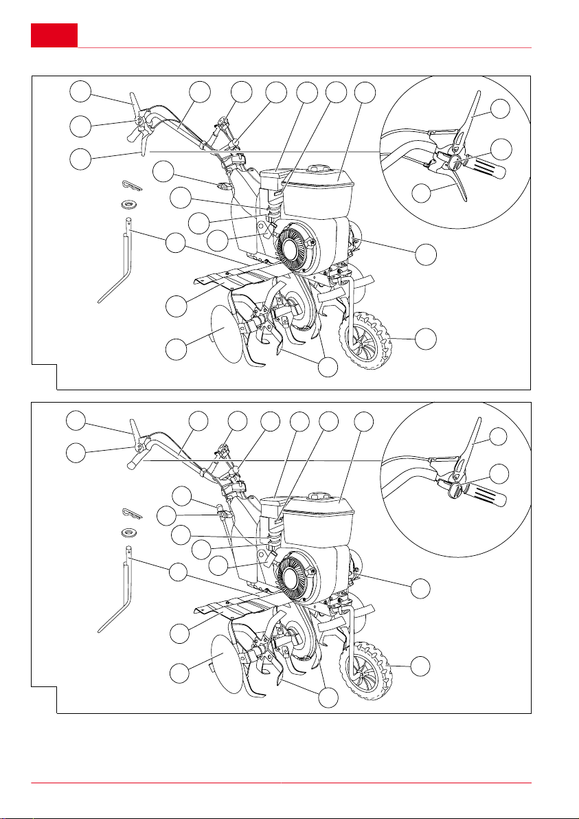
Produktübersicht
Pos. Baugruppen
(01/1) Führungsholm
(01/2) Öltank
(01/3) Motor
(01/4) Benzintank
(01/5) Schutzbleche mit optionaler Schutz-
blechverbreiterung
(01/6) Seitenschutzscheiben
(01/7) Hackmesser
(01/8) Transportrad
(01/9) Bremssporn
Pos. Bedienelemente
(01/10) Kupplungshebel
(01/11) Sicherheitstaste
(01/12) Gashebel
(01/13) Exzenterhebel für Seitenverstellung
des Führungsholms
(01/14) Flügelmuttern für Höhenverstellung
des Führungsholms
8 7505 VR / 7505 V2R
Page 9
Produktbeschreibung
Pos. Bedienelemente
(01a/15) 7505 VR: Hebel für Rückwärtsgang
(01b/15) 7505 V2R: Ganghebel für 2 Vor-
wärtsgänge und 1 Rückwärtsgang
(01/16) Choke-Hebel
(01/17) Benzinhahn
(01/18) Regler für die Motordrehzahl
(01/19) Griff für Starterseil
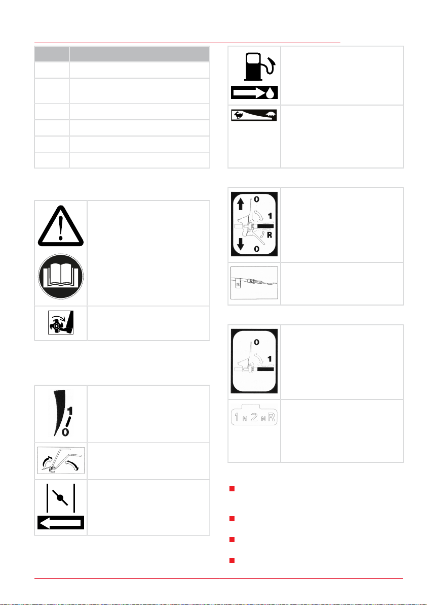
Sicherheitssymbole am Gerät
Sicherheitssymbole an der Motorhacke:
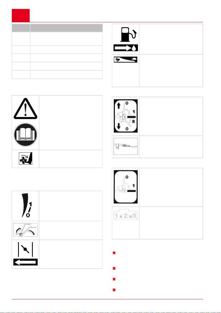
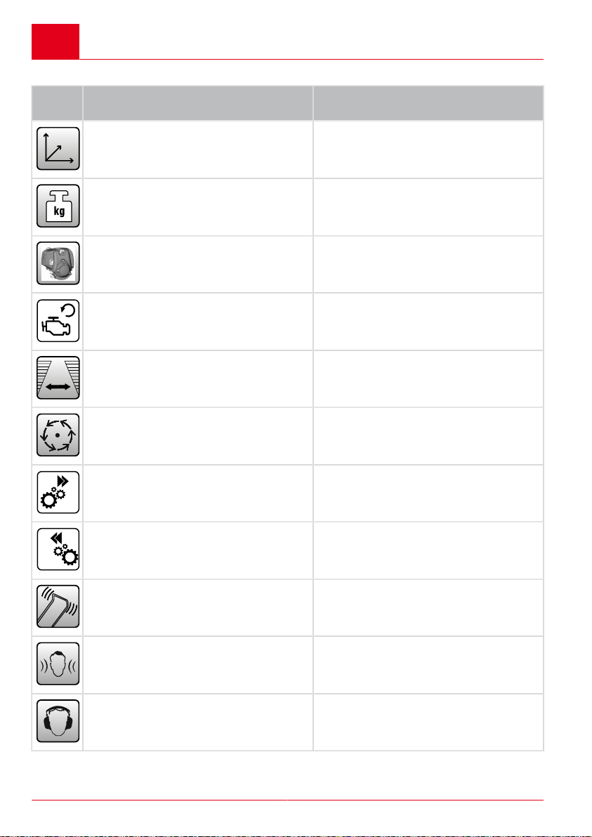
Vor Inbetriebnahme die Betriebsanleitung lesen!
Rotierendes Werkzeug! Hände
und Füße fernhalten!
Sicherheitssymbole am Motor bzw. Benzintank:
siehe Betriebsanleitung des Motors.
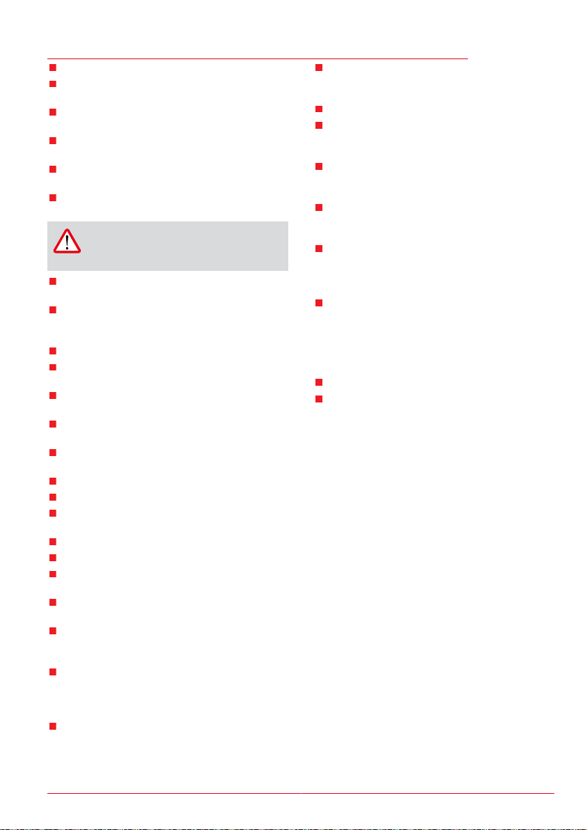
Bediensymbole am Gerät
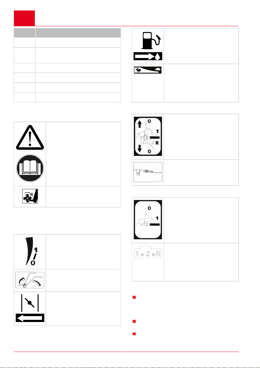
Hebel des Benzinhahns in Pfeilrichtung ON schieben.
Motordrehzahl bzw. Arbeitsgeschwindigkeit einstellen:
Richtung "Hase" = Arbeitsgeschwindigkeit erhöhen.
Richtung "Schildkröte" = Arbeitsgeschwindigkeit verringern.
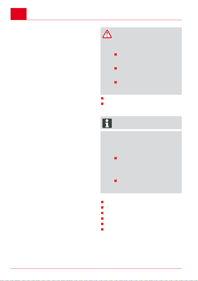
7505 VR:
Aufkleber für Hackmesser:
1 = Hackmesser im Vorwärtsgang.
R = Hackmesser im Rückwärtsgang.
0 = Hackmesser abschalten.
Etikett für Rückwärtsgang-Bowdenzug
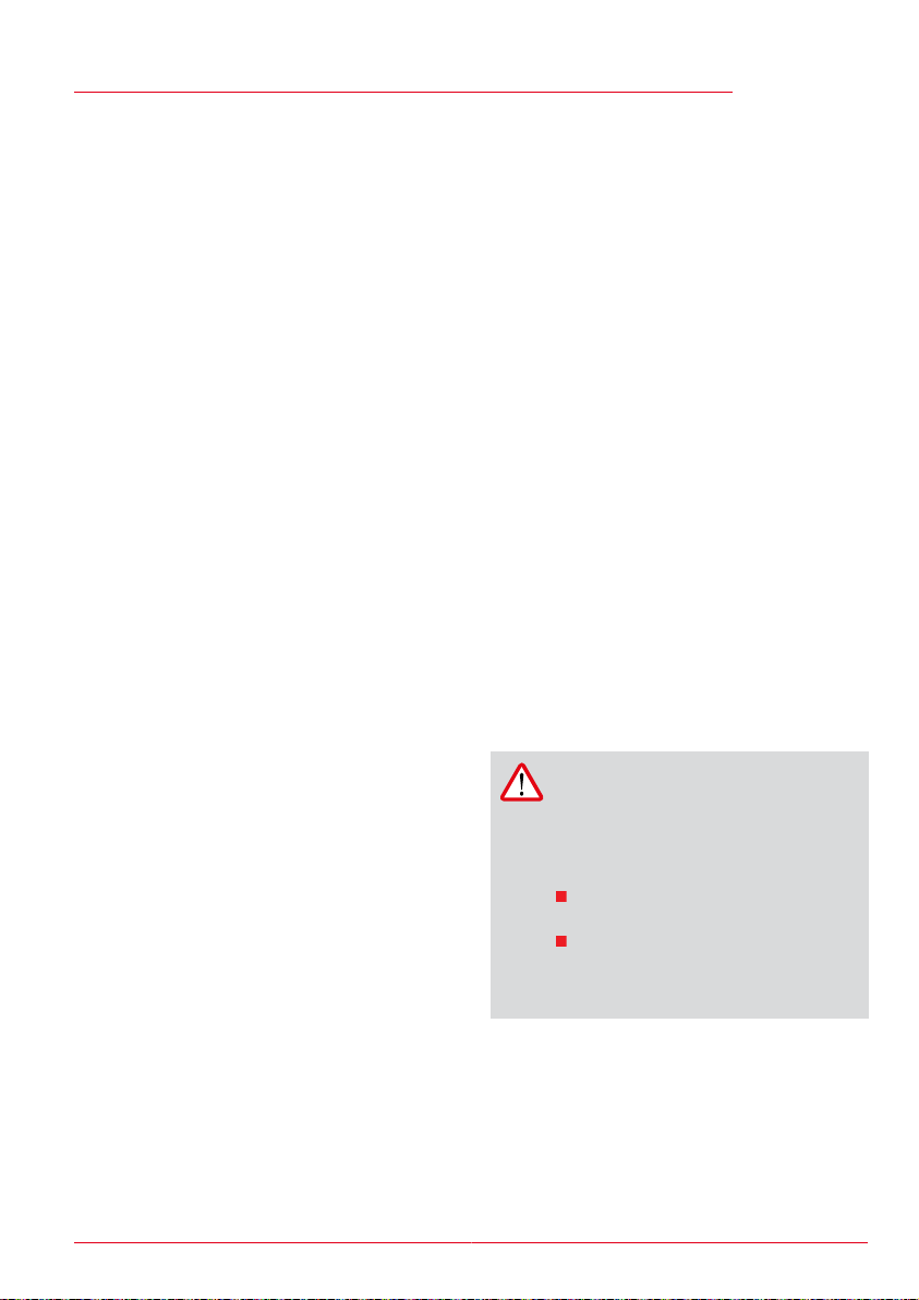
7505 V2R:
Aufkleber für Hackmesser:
1 = Hackmesser zuschalten.
0 = Hackmesser abschalten.
Aufkleber am Gashebel:
1 = Motor starten.
0 = Motor stoppen.
Aufkleber am Führungsholm:
Exzenterhebel lösen und Führungsholm drehen.
Platte für Ganganzeige:
1 = 1. Gang
N = Leerlauf
2 = 2. Gang
N = Leerlauf
R = Rückwärtsgang
SICHERHEITSHINWEISE
Choke-Hebel auf das ChokeZeichen schieben.
441582_a 9
Jugendliche unter 16 Jahren oder Personen,
welche die Bedienungsanleitung nicht kennen, dürfen das Gerät nicht benützen.
Das Gerät nicht auf grobsteinigem Gelände
einsetzen.
Örtliche Bestimmungen zum Mindestalter der
Bedienungsperson beachten.
Keine lose sitzende Kleidung tragen.
Page 10
D
Montage
Festes, rutschsicheres Schuhwerk tragen.
Fremdkörper im Arbeitsbereich entfernen.
Das Gerät darf nicht im gewerblichen Einsatz
betrieben werden.
Gerät nicht unter Einfluss von Alkohol, Dro-
gen oder Medikamenten bedienen.
Landesspezifische Bestimmungen für die Be-
triebszeiten beachten.
Nur bei ausreichendem Tageslicht oder
künstlicher Beleuchtung arbeiten.
ACHTUNG!
Vor Inbetriebnahme immer eine Sichtkontrolle durchführen.
Gerät nur in technisch einwandfreiem Zustand benutzen.
Beachten Sie, dass der Benutzer für Unfälle
und Schäden verantwortlich ist, die anderen
Personen oder deren Eigentum widerfahren
können.
Sicherheits- und Schutzeinrichtungen nicht
außer Kraft setzen.
Hände und Füße nicht in die Nähe rotierender
Teile bringen.
Gerät nie mit laufendem Motor heben oder
tragen.
Beim Arbeiten auf sicheren Stand achten.
Der Benutzer ist für Unfälle mit anderen Per-
sonen und deren Eigentum verantwortlich.
Gerät nicht unbeaufsichtigt lassen.
Auspuff und Motor sauber halten.
Benzin nur in dafür vorgesehenen Behältern
aufbewahren.
Nur im Freien tanken.
Beschädigten Tank oder Tankverschluss
austauschen.
Beschädigte oder verschlissene Teile durch
Original-Ersatzteile ersetzen.
Konstruktions- und Ausführungsänderungen
vorbehalten.
Beim Anlassen (Starten) des Motors darf nie-
mand vor dem Gerät bzw. den Arbeitswerkzeugen (Hackmesser) stehen - der Antrieb
der Hackmesser muss ausgeschaltet sein.
Den An- und Abbau des Transportrades,
bzw. das Verstellen des Bremsspornes nur
bei abgeschaltetem Motor und stehenden
Hackmessern vornehmen.
Beim Fahren mit angebautem Transportrad
den Motor abstellen und Stillstand der Hackmesser abwarten.
Das Benutzen des Gerätes ist nur bei Einhaltung des durch den Führungsholm gegebenen Sicherheitsabstandes erlaubt.
Stets quer zum Hang arbeiten.
Nicht hangauf- und hangabwärts, sowie an
Hängen mit mehr als 10° Neigung arbeiten.
Während der Motor läuft oder bei heißer Ma-
schine darf der Tankverschluss nicht geöffnet
oder Benzin nachgefüllt werden.
Zum Auftanken einen Trichter oder ein Einfüllrohr verwenden, damit kein Kraftstoff auf
den Motor, das Gehäuse oder die Erde verschüttet werden kann.
Falls Benzin übergelaufen ist, darf der Motor
nicht gestartet werden. Das Gerät ist zu reinigen und jeglicher Zündversuch zu vermeiden, bis die Benzindämpfe sich verflüchtigt
haben.
Aus Sicherheitsgründen, nie den Motor mit
abgenutzten oder beschädigten Teilen verwenden. Die Teile müssen ersetzt und dürfen niemals repariert werden. Originalersatzteile verwenden. Nicht gleichwertige Ersatzteile können den Motor beschädigen und Ihre
Sicherheit gefährden.
Beschädigte Auspufftöpfe austauschen.
Die Reglereinstellungen des Motors nicht
verändern.
MONTAGE
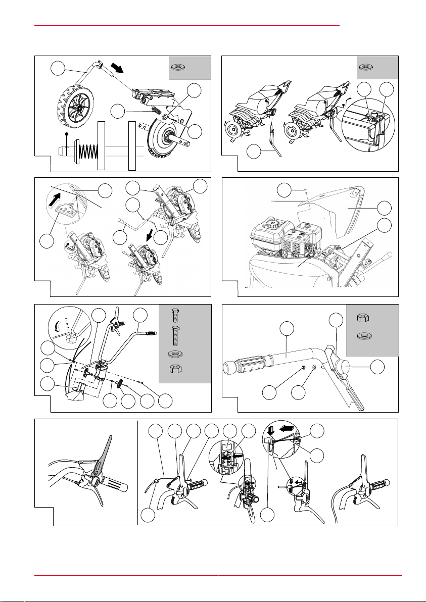
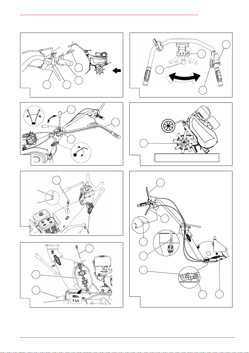
Transportrad montieren (01) (02)
1. Schieben Sie die Radhalterung (02/1) mit
dem Transportrad in den vorderen Aufnahmepunkt des Rahmens ein.
2. Schieben Sie die Feder (02/2) und die Unterlegscheibe (02/3) auf die Radhalterung (02/1)
auf.
3. Schieben Sie den Splint (02/4) in das Loch
der Radhalterung ein, bis er festsitzt.
10 7505 VR / 7505 V2R
Page 11

Montage
Bremssporn montieren (01) (03)
1. Setzen Sie den Bremssporn (03/1) von unten
in das Loch des Rahmens bis zum Anschlag
ein.
2. Stecken Sie die Unterlegscheibe (03/2) auf
den Bremssporn.
3. Stecken Sie das gerade Ende des Federsplints (03/3) in das Loch des Bremssporns
soweit ein, bis der Federsplint einrastet und
sich nicht mehr herausziehen lässt.
Platte zur Ganganzeige und Ganghebel montieren, 7505 V2R (04)
Platte zur Ganganzeige montieren:
1. Setzen Sie die Platte (04/1) zur Ganganzeige
in die Bohrungen des Rahmens (04/2) ein.
Ganghebel montieren:
2. Setzen Sie den Ganghebel (04/3) in die Öse
(A) am Rahmen (04/7) ein.
3. Befestigen Sie den Ganghebel mit Hilfe der
Schraube (04/5) und der Mutter (04/6) an der
Getriebewelle (04/4).
Obere Gehäuseabdeckung montieren, 7505 V2R (05)
1. Setzen Sie die Gehäuseabdeckung (05/1) auf
das Getriebe (05/2) auf. Achten Sie dabei darauf, dass die Bohrung (A) über der Bohrung
(B) liegt.
2. Schrauben Sie die Schraube (05/3) in die
Bohrungen ein.
Führungsholm montieren (06)
1. Schraube (06/1) einstecken und befestigen:
Stecken Sie die Schraube (06/1) durch die
Öse (06/2), in der sich bereits der Bowdenzug befindet. Stecken Sie die Mutter (06/3)
auf und drehen Sie sie fest.
2. Griffe (06/5) für die Höhenverstellung anbringen: Stecken Sie auf die Schrauben (06/4) die
Unterlegscheiben (06/6) auf und drehen Sie
die Griffe locker ein.
3. Führungsholm (06/7) an der Halterung (06/8)
befestigen: Drücken Sie den Exzenterhebel
(06/9) nach unten. Stecken Sie den Führungsholm (06/7) auf die Halterung (06/8) und
drehen Sie die Griffe fest.
Zum Einstellen der Höhe des Führungsholms:
siehe Abschnitt "Höhe des Führungsholms einstellen".
Bowdenzug für den Kupplungshebel montieren (08)
Der Bowdenzug ist bereits am Gerät montiert, er
muss nur mit dem Kupplungshebel (08/3) verbunden werden.
1. Setzen Sie den Bowdenzug (08/1) mit der TKlemme (08/4) in die Öffnung (08/2) des vormontierten Kupplungshebels (08/3) ein.
2. Setzen Sie die T-Klemme (08/4) in die mittlere
Aufnahme (08/3) des Kupplungshebels (08/3)
ein und ziehen Sie kräftig an der T-Klemme,
damit sie einrastet.
3. Setzen Sie die Kunststoffklemme (08/5) in die
Aufnahme (A) ein und drücken Sie sie kräftig
nach unten, bis sie einrastet.
Zur Feineinstellung des Bowdenzuges, siehe Abschnitt "Bowdenzug des Kupplungshebels nachstellen".
Bowdenzug für Rückwärtsgang montieren, 7505 VR (09)
Der Bowdenzug ist bereits am Gerät montiert, er
muss nur mit dem Hebel (09/3) für den Rückwärtsgang verbunden werden. Der Bowdenzug
für den Rückwärtsgang ist mit dem Etikett "R" gekennzeichnet.
1. Stecken Sie den Bowdenzug (09/1) für
den Rückwärtsgang mit der zylinderförmigen
Klemme in die Öffnung (09/2) des Hebels
(09/3) für den Rückwärtsgang ein.
2. Setzen Sie die zylinderförmige Klemme (09/4)
in die mittlere Aufnahme (A) des Hebels
(09/3) für den Rückwärtsgang ein und ziehen
Sie kräftig an der zylinderförmigen Klemme,
damit sie einrastet.
3. Setzen Sie den Regler (09/5) des Bowdenzuges in die Aufnahme (B) des Hebels ein.
Gashebel montieren (07)
1. Stecken Sie die Gashebel-Baugruppe (07/1)
in die Bohrung auf der linken Stange des Führungsholms (07/2).
2. Stecken Sie den Federring (07/3) auf den Gewindebolzen der Gashebel-Baugruppe (07/1)
und schrauben Sie die Mutter (07/4) auf dem
Gewindebolzen fest.
3. Prüfen Sie, ob Sie den Gashebel (07/5) frei
bewegen können.
441582_a 11
Page 12
D
Montage
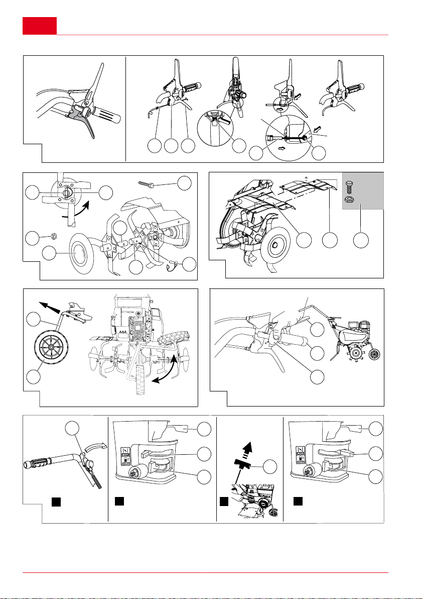
Verbreiterungshacksatz montieren, optional (10) (11)
Hackmesser montieren:
1. Montieren Sie die Seitenschutzscheiben
(10/1) von der Hackmesserwelle (10/2) ab.
2. Setzen Sie die Hackmesserwelle (10/3) des
Verbreiterungshacksatzes so auf die bereits
montierte Hackmesserwelle (10/2) auf, dass
der Schliff der Hackmesser zur Vorderseite
der Motorhacke zeigt.
3. Schieben Sie beide Hackmesserwellen ineinander und drehen Sie dabei beide Hackmesserwellen so, dass die Löcher beider Wellen
übereinstimmen.
4. Stecken Sie den Sicherungsplint (10/4) durch
die Löcher der Hackmesserwellen und sichern Sie ihn mit der Sicherungsarretierung
(10/5) gegen Herausrutschen. Die Sicherungsarretierung muss in die Rotationsrichtung A gedreht sein, genau wie im Bild (10)
dargestellt.
VORSICHT!
Verletzungsgefahr durch sich ab-
lösende Maschinenteile!
Bei entgegen der Rotationsrichtung gedrehter Sicherungsarretierung kann sich der Verbreiterungshacksatz bei laufender Motorhacke
lösen und Personen verletzen.
Sicherungsarretierung in Rotationsrichtung einsetzen.
5. Stecken Sie die Seitenschutzscheiben (10/1)
wieder auf und befestigen Sie sie mit der
Schraube (10/6) und der Mutter (10/7).
Schutzblechverbreiterung montieren:
1. Setzen Sie die Schutzblechverbreiterung
(11/1) auf das bereits vorhandene Schutzblech (11/2), wie in Bild (11) gezeigt.
2. Befestigen Sie die Schutzblechverbreiterung am vorhandenen Schutzblech mit den
Schrauben (11/3).
INBETRIEBNAHME
Bowdenzüge einstellen
Siehe Kapitel "Wartung und Pflege".
Höhe des Führungsholms einstellen (6)
Die Höhe des Führungsholms ist abhängig von Ihrer Körpergröße. Der Führungsholm sollte sich in
Hüfthöhe befinden.
1. Drehen Sie beide Griffe (06/5) für die Höhenverstellung des Führungsholms soweit auf,
dass sich der Führungsholm nach unten oder
oben drücken lässt.
2. Drücken Sie den Führungsholm soweit nach
unten oder oben, bis er sich in der gewünschten Höhe befindet.
3. Ziehen Sie beide Griffe für die Höhenverstellung wieder fest.
BEDIENUNG
Befüllung mit Kraftstoff
Siehe Betriebsanleitung des Motors.
Motorhacke zum Einsatzort rollen (12)
Mit dem Transportrad (12/1) können Sie die Motorhacke leicht und bequem zum Einsatzort rollen.
1. Wenn das Transportrad eingeklappt ist: Ziehen Sie das Transportrad (12/1) an der Radhalterung (12/2) heraus (Richtung A). Klappen Sie es nach unten in die Fahrposition und
lassen Sie es los, damit es einrastet.
2. Heben Sie die Motorhacke am Führungsholm
an, bis sie auf dem Transportrad (12/1) steht.
3. Schieben Sie die Motorhacke zum Einsatzort.
4. Transportrad einklappen für die Bodenbearbeitung: Ziehen Sie das Transportrad (12/1)
an der Radhalterung (12/2) heraus (Richtung
A). Klappen Sie es nach oben in die waagerechte Position und lassen Sie es los, damit
es einrastet.
12 7505 VR / 7505 V2R
Page 13

Bedienung
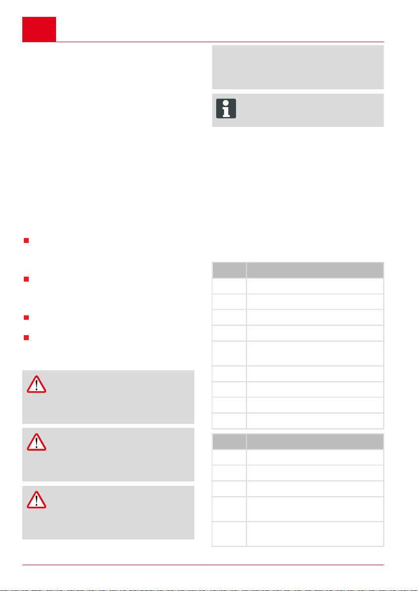
Motor starten und stoppen (14)
Motor starten:
1. Öffnen Sie den Benzinhahn durch Schieben
des Hebels (14/1) in Pfeilrichtung ON.
2. Wenn der Motor kalt ist:
Schieben Sie den Choke-Hebel (14/2) auf das
Choke-Zeichen. Verwenden Sie diese Position ausschließlich zum Starten des Motors.
3. Motordrehzahl bzw. Arbeitsgeschwindigkeit
einstellen:
Arbeitsgeschwindigkeit erhöhen: Schieben
Sie den Regler (14/3) für die Motordrehzahl in
Richtung "MAX. (Hase)".
Arbeitsgeschwindigkeit verringern: Schieben
Sie den Regler (14/3) für die Motordrehzahl in
Richtung "MIN. (Schildkröte)".
4. Drehen Sie den Gashebel (14/4) auf
Position "1".
In Position "1" läuft der Motor mit der am Regler für die Motordrehzahl eingestellten Drehzahl. In Position "0" läuft der Motor nicht.
5. Ziehen Sie das Starterseil am Griff (14/5) zügig heraus und lassen Sie es danach langsam
wieder aufrollen. Der Motor beginnt zu laufen.
Wenn der Motor nicht läuft: Prüfen Sie, ob alle
vorhergehenden Arbeitsschritte durchgeführt
wurden und ziehen Sie dann das Starterseil
erneut.
6. Wenn der Motor rund läuft: Schieben Sie
den Choke-Hebel (14/2) langsam bis zum Anschlag zurück. Beginnt der Motor zu stottern,
schieben Sie den Choke-Hebel wieder ein
wenig in Richtung Choke-Zeichen.
Motor stoppen:
1. Drehen Sie den Gashebel (14/4) auf Position
"0".
2. Schließen Sie den Benzinhahn (14/1).
Hackmesser zu- und abschalten (13)
Hackmesser zuschalten:
1. Führungsholm am Griff (13/1) anfassen.
2. Sicherheitstaste (13/2) drücken.
3. Kupplungshebel (13/3) fest nach unten an
den Führungsholm drücken.
Nach der Hälfte des Hebelweges beginnen sich
die Hackmesser zu drehen und die Motorhacke
setzt sich in Bewegung. Nachdem der Kupplungshebel vollständig nach unten gedrückt wurde, sind
die Hackmesser vollständig zugeschaltet.
Hackmesser abschalten:
1. Kupplungshebel (13/3) loslassen.
Die Motorhacke stoppt.
Bremssporn benutzen
Wenn Sie den Führungsholm der Motorhacke und
damit auch den Bremssporn nach unten drücken,
verlangsamt sich die Geschwindigkeit der Motorhacke bzw. sie bleibt stehen.
Wenn Sie den Führungsholm der Motorhacke und
damit auch den Bremssporn anheben, erhöht sich
die Geschwindigkeit der Motorhacke.
Rückwärtsgang zu- und abschalten, 7505 VR (15)
1. Zum Stoppen der Hackmesser: Kupplungshebel (15/3) loslassen.
2. Hebel (15/4) für Rückwärtsgang bis zum Anschlag nach oben ziehen.
3. Zum Starten der Hackmesser: Sicherheitstaste (15/2) drücken und Kupplungshebel
(15/3) fest nach unten an den Führungsholm
(15/1) drücken.
Gangschaltung bedienen, 7505 V2R (16)
Mit dem Ganghebel (16/1) können Sie 2 Vorwärtsgänge und 1 Rückwärtsgang schalten. Der
erste Vorwärtsgang ist für harte Böden bestimmt,
die Hackmesser drehen sich langsam. Der zweite
Vorwärtsgang ist für weniger harte Böden bestimmt, die Hackmesser drehen sich schneller.
1. Zum Stoppen der Hackmesser: Kupplungshebel (16/3) loslassen.
2. Ganghebel (16/1) so drehen, dass er mit dem
gewünschten Gang auf der Platte (16/2) für
die Ganganzeige übereinstimmt (1 = 1. Gang,
2 = 2. Gang, R = Rückwärtsgang).
3. Zum Starten der Hackmesser: Sicherheitstaste (16/4) drücken und Kupplungshebel
(16/3) fest nach unten an den Führungsholm
drücken.
Führungsholm seitlich verstellen (17)
Die Seitenverstellung des Führungsholms macht
es möglich, dass die bereits bearbeitete Fläche
nicht betreten werden muss. Der Führungsholm
ist nach links und rechts jeweils um 35° verstellbar.
1. Ziehen Sie den Exzenterhebel (17/1) nach
oben. Der Führungsholm (17/2) wird aus dem
Halter (17/3) ausgekuppelt.
2. Drehen Sie den Führungsholm (17/2) nach
links oder rechts bis zum Anschlag und halten
Sie ihn in dieser Position.
3. Drücken Sie den Exzenterhebel (17/1) nach
unten. Der Führungsholm (17/2) ist arretiert.
441582_a 13
Page 14
D
Wartung und Pflege
WARTUNG UND PFLEGE
WARNUNG!
Gefahr schwerer Verletzungen bei
Wartungs- und Pflegearbeiten!
Durch sich bewegende Maschinenteile
können Personen schwer verletzt werden.
Vor allen Wartungs- und Pflegearbeiten immer Motor abschalten und
den Zündkerzenstecker ziehen!
Motor kann nachlaufen. Nach dem
Ausschalten vergewissern, dass der
Motor steht!
Bei Wartungs- und Pflegearbeiten
an den Hackmessern immer Arbeitshandschuhe tragen!
Das Gerät nach jedem Gebrauch reinigen.
Gerät nicht mit Wasser abspritzen! Eindrin-
gendes Wasser (Zündanlage, Vergaser...)
kann zu Störungen führen.
HINWEIS
Wenn das Gerät zur Seite geneigt wird,
muss der Vergaser nach oben zeigen!
ACHTUNG!
Gefahr der Umweltverschmutzung
durch Altöl
Durch illegal - z. B. in das Kanalnetz,
in das Erdreich oder in Gewässer - entsorgtes Altöl entstehen schwere Umweltschäden!
Entsorgen Sie Altöl immer entsprechend den gesetzlichen Bestimmungen, z. B. bei Altölannahmestellen. Jede Verkaufstelle, die Öl verkauft, ist gesetzlich zur Annahme
von Altöl verpflichtet.
Lassen Sie Altöl nie in das Kanalnetz, in das Erdreich oder in Gewässer ab.
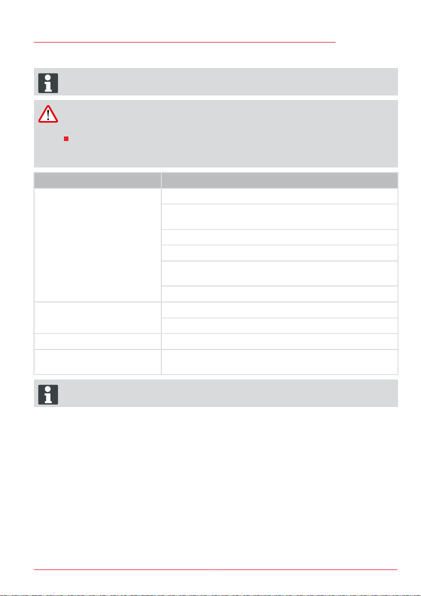
Fachmännische Überprüfung ist erforderlich:
nach Auffahren auf ein Hindernis
bei plötzlichem Stillstand des Motors
bei Getriebeschaden
bei defektem Keilriemen
bei verbogenem Messer
bei verbogener Motorwelle
Getriebeöl des Kettengetriebes wechseln (18)
Alle 100 Arbeitsstunden muss das Getriebeöl des
Kettengetriebes gewechselt werden (Menge: 0,5
l, Viskosität SAE 80). Zum Wechseln des Getriebeöls muss die Motorhacke warm sein.
1. Montieren Sie den Bremssporn ab.
2. Schrauben Sie die Verschlussschraube der
Einfüllöffnung (18/1) heraus.
3. Kippen Sie die Motorhacke nach hinten in Position A.
4. Saugen Sie das alte Öl mit einer Pumpe ab.
5. Füllen Sie neues Öl ein. Erforderliche Ölmenge ca. 0,5 l.
6. Messen Sie zur Überprüfung der eingefüllten
Ölmenge den Ölstand: Motorhacke nach hinten kippen. Das Öl muss aus der Einfüllöffnung ausfliesen, kurz bevor die Motorhacke
den Boden berührt.
7. Schrauben Sie die Verschlussschraube wieder in die Einfüllöffnung (18/1) ein.
8. Entsorgen Sie das Altöl entsprechend den gesetzlichen Bestimmungen bei einer Altölannahmestelle.
Getriebeöl des Schaltgetriebes wechseln, 7505 V2R (19) (20)
Alle 60 Arbeitsstunden muss das Getriebeöl des
Schaltgetriebes gewechselt werden (Menge: 0,9
l, Viskosität SAE 80). Zum Wechseln des Getriebeöls muss die Motorhacke warm sein.
Ölstand kontrollieren:
1. Stellen Sie die Motorhacke auf eine ebene
Fläche.
2. Ziehen Sie den Ölmessstab (19/1) heraus
und kontrollieren Sie, ob der Ölstand zwischen den Markierungen "Min." und "Max."
liegt. Wenn der Ölstand unter der Markierung
"Min." liegt, muss Öl nachgefüllt werden.
3. Stecken Sie den Ölmessstab wieder ein.
Öl ablassen:
1. Ziehen Sie den Ölmessstab (20/1) heraus.
2. Stellen Sie einen Auffangbehälter (B) mit mindestens 1 Liter Fassungsvermögen unter das
Schaltgetriebe (20/2).
3. Schrauben Sie die Ölablassschraube (20/3)
heraus.
4. Lassen Sie das Öl vollständig in den Auffangbehälter (B) ablaufen.
5. Schrauben Sie die Ölablassschraube (20/3)
wieder ein.
14 7505 VR / 7505 V2R
Page 15

Wartung und Pflege
Öl einfüllen:
1. Füllen Sie neues Öl (Menge: 0,9 l, Viskosität
SAE 80) über die Öffnung (A) des Ölmessstabes wieder in das Schaltgetriebe ein.
2. Stecken Sie den Ölmessstab (20/1) wieder
ein.
3. Kontrollieren Sie, ob der Ölstand korrekt ist
(siehe "Ölstand kontrollieren").
Motoröl wechseln
Siehe Betriebsanleitung des Motors.
Luftfilter und Zündkerze wechseln
Siehe Betriebsanleitung des Motors.
Bowdenzug des Gashebels nachstellen
Siehe Betriebsanleitung des Motors.
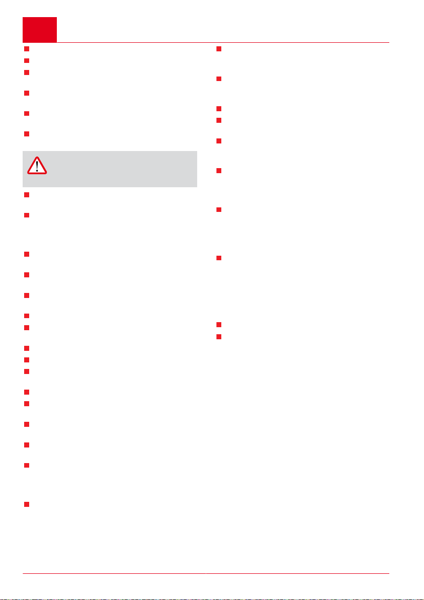
Bowdenzüge für Kupplungshebel und Rückwärtsgang (nur 7505 VR) nachstellen (21)
Die Feineinstellung eines Bowdenzuges erfolgt
mit der jeweiligen Stellschraube an den Bowdenzugenden. Eine Stellschraube befindet sich am
Hebel auf dem Führungsholm und die andere
Stellschraube befindet sich am Befestigungspunkt der Motorkupplung bzw. am Befestigungspunkt des Motorgetriebes.
Der Weg des Bowdenzuges für die Hackmesser
muss so eingestellt sein, dass sich die Hackmesser nach der Hälfte des Hebelweges am Kupplungshebel (21/1) beginnen zu drehen. Wenn der
Kupplungshebel (21/1) oder der Hebel (21/7) für
den Rückwärtsgang vollständig an den Führungsholm gedrückt wurde, muss die dazugehörige
Spannfeder (21/2) um 8-10 mm auseinandergezogen sein.
1. Lösen Sie am jeweiligen Bowdenzug die Kontermutter an der Stellschraube. Für den Kupplungshebel: (21/3) und (21/4). Für den Hebel
des Rückwärtsgangs: (21/5) und (21/6).
2. Drehen Sie die Stellschraube, um den Weg
des Bowdenzuges zu verlängern oder zu verkürzen.
3. Ziehen Sie die Kontermutter wieder fest.
LAGERUNG
WARNUNG!
Brandgefahr - Gefahr von schweren
Personen- und Sachschäden!
Durch explodierende Kraftstoffdämpfe
können Personen schwer verletzt werden und es können schwere Sachschäden entstehen.
Betanktes Gerät nur an einem gut
belüfteten Ort aufbewahren.
Betanktes Gerät nicht in Gebäuden aufbewahren, in denen Kraftstoffdämpfe mit offenem Feuer oder
Funken in Berührung kommen können.
441582_a 15
Page 16

D
1
Fwd
1
Rwd
TECHNISCHE DATEN
Technische Daten
7505 VR
Art.-Nr. 127321
ca. 1500 x 750 x 1150 mm ca. 1500 x 750 x 1150 mm
51 kg 58 kg
Honda GP 160 Honda GP 160
3200 min-1 / 3,6 kW 3200 min-1 / 3,6 kW
50 – 75 cm 50 – 75 cm
max. 125 min
1 2
-1
7505 V2R
Art.-Nr. 127322
max. 125 min
-1
1 1
7,39 m/s2 (K= +/-0,22 m/s2)
EN 709e, ISO 5349
83,8 dB(A) 83,8 dB(A)
95,4 dB(A) 95,4 dB(A)
16 7505 VR / 7505 V2R
7,39 m/s2 (K= +/-0,22 m/s2)
EN 709e, ISO 5349
Page 17
Hilfe bei Störungen
HILFE BEI STÖRUNGEN
HINWEIS
HINWEIS: Vor allen Wartungs- und Reinigungsarbeiten den Zündkerzenstecker abziehen.
WARNUNG!
Verletzungsgefahr und Sachschäden durch unsachgemäße Reparaturen!
Unsachgemäße Reparaturen können zu schweren Verletzungen und zu Sachschäden führen.
Versuchen Sie niemals, aufwändige Reparaturen ohne die erforderlichen Werkzeuge und
technischen Kenntnisse durchzuführen.
Bei nicht fachgerecht ausgeführten Reparaturen erlischt automatisch jeder Garantieanspruch
und jede Haftung des Herstellers.
Störung Beseitigung
Motor springt nicht an.
Benzinhahn öffnen und/oder Benzin einfüllen.
Bei kaltem Motor: Choke-Hebel auf das Choke-Zeichen schieben.
Gashebel auf Position "1" drehen.
Zündkerzenstecker auf die Zündkerze stecken.
Zündkerze ist defekt oder unsauber, falscher Elektrodenabstand:
Siehe Betriebsanleitung des Motors.
Luftfilter ist verschmutzt: Siehe Betriebsanleitung des Motors.
Luftfilter ist verschmutzt: Siehe Betriebsanleitung des Motors.Motorleistung lässt nach.
Hackmesser von Pflanzenresten reinigen.
Hackmesser drehen nicht. Bowdenzug für Hackmesser nachstellen.
Wenn die Hackmesser nicht fest mit der Getriebewelle verbunden sind: Autorisierte Service-Werkstätte aufsuchen.
HINWEIS
HINWEIS: Bei nicht behebbaren Störungen eine autorisierte Service-Werkstätte aufsuchen.
441582_a 17
Page 18

D
EG-Konformitätserklärung
EG-KONFORMITÄTSERKLÄRUNG
Wir erklären hiermit, dass dieses Produkt in der auf dem Markt vertriebenen Form die Anforderungen der harmonisierten EU-Richtlinien,
der EU-Sicherheitsstandards und die produktspezifischen Standards erfüllt.
Produkt Hersteller Bevollmächtigter
Motorhacke
Seriennummer
G2222225
Typ EU-Richtlinien Harmonisierte Normen
7505 VR
7505 V2R
AL-KO Geräte GmbH
Ichenhauser Str. 14
D-89359 Kötz
Deutschland
2006-42-EG
2014-30-EU
2000-14-EG
Konformitätserklärung Kötz, 2016-01-30
2000-14-EG Anhang ( V )
Andreas Hedrich
Ichenhauser Str. 14
D-89359 Kötz
Deutschland
EN 709: 1997 + A4:2009
EN ISO: 14982
Wolfgang Hergeth
Managing Direktor
18 7505 VR / 7505 V2R
Page 19
Translation of the original instructions for use
TRANSLATION OF THE ORIGINAL
INSTRUCTIONS FOR USE
Contents
About these instructions for use.......................19
Product description.......................................... 19
Safety instructions............................................20
Installation........................................................ 21
Start-up.............................................................23
Operation..........................................................23
Maintenance and care..................................... 24
Storage.............................................................25
Technical data..................................................26
Help in case of malfunctions............................27
EU declaration of conformity............................28
ABOUT THESE INSTRUCTIONS FOR USE
It is essential to read through these instructions for use carefully before start-up. This
is essential for safe working and trouble-free
handling.
Always safeguard these instructions for use
so that they can be consulted if you need any
information about the appliance.
Only pass on the appliance with these instructions for use to other persons.
Comply with the safety and warning information in these instructions for use.
Legends and signal words
DANGER!
Denotes an immediately dangerous situation which will result in fatal or serious
injury if not avoided.
WARNING!
Denotes a potentially dangerous situation which can result in fatal or serious
injury if not avoided.
CAUTION!
Denotes a potentially dangerous situation which can result in minor or moderate injury if not avoided.
CAUTION!
Denotes a situation which can result in
material damage if not avoided.
ADVICE
NOTE: Special instructions for ease of
understanding and handling.
PRODUCT DESCRIPTION
Designated use
This device is only intended for use on pre-cultivated soil.
This device is not suitable for use on solid soil,
e.g. compacted turf.
The continued use of this device with original
spare parts is only allowed in accordance with its
purpose. Any other use is not permitted.
Product overview
Item Assemblies
(01/1) Handlebar
(01/2) Oil tank
(01/3) Motor
(01/4) Petrol tank
(01/5) Guard plates with optional guard
plate extension
(01/6) Lateral protective discs
(01/7) Tiller blades
(01/8) Transport wheel
(01/9) Depth skid
Item Controls
(01/10) Clutch lever
(01/11) Safety button
(01/12) Throttle lever
(01/13) Cam lever for lateral adjustment of
the handlebar
(01/14) Wing nuts for height adjustment of
the handlebar
(01a/15) 7505 VR: Reverse lever
441582_a 19
Page 20
en
Product description
Item Controls
(01b/15) 7505 V2R: Gear lever for 2 forward
gears and 1 reverse gear
(01/16) Choke lever
(01/17) Petrol cock
(01/18) Controller for the motor speed
(01/19) Grip for starter rope
Safety symbols on the appliance
Safety symbols on the cultivator:
Read the operating instructions
before starting operation.
Rotating tool! Keep your hands
and feet away!
For the safety symbols on the motor or petrol tank,
see the operating instructions of the motor.
Operating symbols on the appliance
Push the lever of the petrol cock
ON in the direction of the arrow.
Adjusting the motor speed or
work speed:
Direction of the ”Hare” = increase work speed.
Direction of the ”Tortoise” = decrease work speed.
7505 VR:
Sticker for tiller blades:
1 = tiller blades in forward gear.
R = tiller blades in reverse gear.
0 = stop tiller blades.
Label for reverse gear Bowden
cable
7505 V2R:
Sticker for tiller blades:
1 = start tiller blades.
0 = stop tiller blades.
Sticker on the gas lever:
1 = Start motor.
0 = Stop motor.
Plate for gear display:
1 = 1st gear
Sticker on the handlebar:
Release the cam lever and turn
the handlebar.
Push the choke lever towards
the choke symbol.
20 7505 VR / 7505 V2R
SAFETY INSTRUCTIONS
Young people under 16 years of age, and
people who do not know the instructions for
use, are not allowed to use the machine.
The device should not be used on rocky terrain.
Comply with local regulations on the minimum age of people operating the machine.
Do not wear loose clothing.
N = idle
2 = 2nd gear
N = idle
R = reverse gear
Page 21
Installation
Wear sturdy, non-slip shoes.
Remove foreign bodies from the working
area.
The machine is not allowed to be used in
commercial applications.
Do not operate the machine if you are under
the influence of alcohol, drugs or medication.
Comply with working time regulations in force
in your country.
Only work with sufficient daylight or artificial
lighting.
CAUTION!
Always perform a visual check prior to
start-up.
Only use the machine if it is in perfect technical condition.
Note that the user is responsible for accidents
and damage that may befall other persons or
their property.
Do not disable safety and protective devices.
Do not place your hands and feet close to any
rotating parts.
Never lift or carry the machine when the en-
gine is running.
Make sure you can stand securely when
working.
The user is responsible for accidents invol-
ving other people and their property.
Do not leave the machine unsupervised.
Keep the exhaust and motor clean.
Only use appropriate containers to store pe-
trol.
Only refuel outdoors.
Renew the tank or tank cap if damaged.
Only replace damaged or worn parts by ge-
nuine spare parts.
Subject to changes in design and configura-
tion.
No one should be standing in front of the de-
vice and/or tiller blades when starting the motor - the tiller blade drive must be turned off.
When attaching and removing the transport
wheel and/or when adjusting the depth skid,
the motor must be turned off and the tiller blades must be upright.
When moving the device using the attached
transport wheel, turn off the motor and wait
for the tiller blades to come to a standstill.
The device may only be operated by maintaining the safety distance provided by the
handlebar.
Always operate parallel to the slope.
Do not operate the device up or down the
slope, as well as on slopes with a gradient of
more than 10°.
Do not open the tank cap or refuel with petrol
while the motor is still running and while the
machine is still hot.
Use a funnel or a filler pipe when refuelling so
that no fuel is spilled on the engine, the deck
or the ground.
Do not start the engine if petrol has overflowed. The appliance may be cleaned, and
any attempt at ignition may be made, only
when the petrol vapours have dissipated.
For safety reasons, never use the machine
with worn or damaged parts. The parts must
be replaced and are never allowed to be repaired. Use original spare parts. Non-equivalent spare parts can damage the motor and
endanger the operator.
Renew exhaust silencers if damaged.
Do not change the engine governor settings.
INSTALLATION
Assembling the transport wheel (01) (02)
1. Push the wheel mount (02/1) with the transport wheel into the front support point of the
frame.
2. Push the spring (02/2) and the washer (02/3)
onto the wheel mount (02/1).
3. Push the split pin (02/4) into the hole of the
wheel mount until it fits tightly.
Assembling the depth skid (01) (03)
1. Insert the depth skid (03/1) into the hole of the
frame up to the stop from below.
2. Place the washer (03/2) on the depth skid.
3. Insert the straight end of the spring split pin
(03/3) into the hole of the depth skid until the
spring split pin locks in place and cannot be
pulled out again.
Assembling the plate for the gear display and gear lever, 7505 V2R (04)
Assembling the plate for the gear display:
1. Insert the plate (04/1) for the gear display into
the holes in the frame (04/2).
441582_a 21
Page 22

en
Installation
Assembling the gear lever:
2. Insert the gear lever (04/3) into the eye (A) on
the frame (04/7).
3. Attach the gear lever on the gear shaft (04/4)
using the screw (04/5) and the nut (04/6).
Mounting the upper housing cover, 7505 V2R (05)
1. Place the housing cover (05/1) on the transmission (05/2). Ensure that the hole (A) is
above the hole (B).
2. Screw the screw (05/3) into the holes.
Mounting the handlebar (06)
1. Inserting and tightening the screw (06/1): Insert the screw (06/1) through the eye (06/2)
in which the Bowden cable is already located.
Put on the nut (06/3) and tighten.
2. Attaching grips (06/5) for the height adjustment: Place the washers (06/6) on the screws
(06/4) and lightly screw in the grips.
3. Fixing the handlebar (06/7) to the holder
(06/8): Press the cam lever (06/9) down.
Place the handlebar (06/7) on the holder
(06/8) and screw the grips tight.
To adjust the height of the handlebar, see section
“Setting the height of the handlebar".
Mount the Bowden cable for the clutch lever (08)
The Bowden cable is already mounted on the appliance; it only needs to be connected to the clutch
lever (08/3).
1. Insert the Bowden cable (08/1) with the T-terminal (08/4) into the opening (08/2) of the premounted clutch lever (08/3).
2. Insert the T-terminal (08/4) into the middle
support (08/3) of the clutch lever (08/3) and
pull the T-terminal firmly until it locks in place.
3. Insert the plastic terminal (08/5) into the support (A) and firmly press it down until it locks
in place.
For fine adjustment of the Bowden cable, see section “Readjusting the Bowden cable of the clutch
lever".
Mounting the Bowden cable for the reverse gear, 7505 VR (09)
The Bowden cable is already mounted on the appliance; it only needs to be connected to the lever
(09/3) for the reverse gear. The Bowden cable for
the reverse gear is marked with the label “R”.
1. Insert the Bowden cable (09/1) for the reverse gear with the cylindrical terminal into the
opening (09/2) of the lever (09/3) for the reverse gear.
2. Insert the cylindrical terminal (09/4) into the
middle support (A) of the lever (09/3) for the
reverse gear and pull on the cylindrical terminal firmly until it locks in place.
3. Insert the controller (09/5) of the Bowden cable into the support (B) of the lever.
Mounting the gas lever (07)
1. Insert the gas lever assembly (07/1) into the
hole on the left bar of the handlebar (07/2).
2. Place the spring washer (07/3) onto the threaded pin of the gas lever assembly (07/1) and
screw the nut (07/4) firmly onto the threaded
pin.
3. Check that the gas lever (07/5) can move freely.
Mount the wide tiller set, option (10) (11)
Mounting the tiller blades:
1. Remove the lateral protective discs (10/1)
from the tiller blade shaft (10/2).
2. Place the tiller blade shaft (10/3) of the wide
tiller set onto the already mounted tiller blade
shaft (10/2) in such way that the edge of the
tiller blades points towards the front side of
the cultivator.
3. Push both tiller blade shafts into each other,
turning both tiller blade shafts in such a way
that the holes of the two shafts coincide.
4. Push the split safety pin (10/4) through the holes of the tiller blade shafts and secure against
sliding out again with the safety locking mechanism (10/5). The safety locking mechanism must be rotated in rotation direction A,
exactly as displayed in the figure (10).
CAUTION!
Risk of injury due to detaching
machine parts!
If the safety locking mechanism rotates counter to the direction of rotation, the wide tiller set can detach
if the cultivator is running and injure
people.
Insert the safety locking mechanism in the direction of rotation.
5. Replace the lateral protective discs (10/1) and
attach them with the screw (10/6) and the nut
(10/7).
22 7505 VR / 7505 V2R
Page 23

Start-up
Mounting the guard plate extension:
1. Place the guard plate extension (11/1) on the
already available guard plate (11/2) as shown
in the figure (11).
2. Attach the guard plate extension to the existing guard plate with the screws (11/3).
START-UP
Adjusting Bowden cables
See chapter “Maintenance and care".
Adjusting the height of the handlebar (6)
The height of the handlebar depends on your
body height. The handlebar should be at waist
height.
1. Turn both grips (06/5) for the height adjustment of the handlebar open until the handlebar can be pressed down or up.
2. Press the handlebar down or up until it is at
the required height.
3. Retighten both grips for the height adjustment.
OPERATION
Fuel fill
See operating instructions of the motor.
Roll the cultivator to the place where it is to be used (12)
The cultivator is easy to roll to the place of operation using the transport wheel (12/1).
1. If the transport wheel is folded in: Pull out (direction A) the transport wheel (12/1) on the
wheel mount (12/2). Fold it down into the drive
position and release it so it can lock in place.
2. Lift the cultivator using the handlebar until it is
on the transport wheel (12/1).
3. Push the cultivator to the place of operation.
4. Folding in the transport wheel for tilling: Pull
out (direction A) the transport wheel (12/1) on
the wheel mount (12/2). Fold it upwards into
the horizontal position and release it so it can
lock in place.
Starting and stopping the motor (14)
Starting the motor:
1. Open the petrol cock by pushing the lever
(14/1) in the ON arrow direction.
2. If the motor is cold:
Push the choke lever (14/2) towards the
choke symbol. Only use this position for starting the motor.
3. Adjusting the motor speed or work speed:
Increasing the work speed: Push the controller (14/3) for the motor speed in the “MAX.
(Hare)” direction.
Decreasing the work speed: Push the controller (14/3) for the motor speed in the “MIN.
(Tortoise)” direction.
4. Rotate the gas lever (14/4) to position “1”.
In position “1” the motor runs at the speed set
on the controller. The motor does not start in
position “0”.
5. Use the grip (14/5) to quickly pull out the starter rope and then let it slowly roll up again.
The motor starts to run.
If the motor does not run: Check that all previous work steps have been carried out and
then pull the starter rope again.
6. When the motor is running smoothly: Slowly
push the choke lever (14/2) back to the stop.
If the motor starts stuttering, push the choke
lever slightly back in the direction of the choke
symbol.
Stopping the motor:
1. Rotate the gas lever (14/4) to position "0".
2. Close the petrol cock (14/1).
Starting and stopping the tiller blades (13)
Starting the tiller blades:
1. Hold the handlebar by the grip (13/1).
2. Press the safety button (13/2).
3. Press the clutch lever (13/3) on the handlebar
firmly downwards.
After the lever has travelled halfway, the tiller blades begin to rotate and the cultivator starts moving. After the clutch lever has been pressed fully
downwards, the tiller blades have been completely started.
Stopping the tiller blades:
1. Release the clutch lever (13/3).
The cultivator stops.
441582_a 23
Page 24
en
Operation
Use the depth skid
When the handlebar of the cultivator – and thus
also the depth skid – is pressed down, the speed
of the cultivator decreases or it stops.
When the handlebar of the cultivator – and thus
also the depth skid – is lifted upwards, the speed
of the cultivator increases.
Engaging/releasing reverse gear, 7505 VR (15)
1. To stop the tiller blades: Release the clutch
lever (15/3).
2. Pull the lever (15/4) for reverse gear upwards
up to the stop.
3. To start the tiller blades: Press the safety button (15/2) and firmly press the clutch lever
(15/3) on the handlebar (15/1) downwards.
Operating the gear shift, 7505 V2R (16)
The gear lever (16/1) can be used to switch 2
forwards gears and 1 reverse gear. The first forwards gear is intended for hard ground; the tiller
blades turn slowly. The second forwards gear is
intended for less hard ground; the tiller blades turn
faster.
1. To stop the tiller blades: Release the clutch
lever (16/3).
2. Turn the gear lever (16/1) in such a way that it
coincides with the required gear on the plate
(16/2) for the gear display (1 = 1st gear, 2 =
2nd gear, R = reverse gear).
3. To start the tiller blades: Press the safety button (16/4) and firmly press the clutch lever
(16/3) on the handlebar downwards.
Adjusting the sideways position of the handlebar (17)
Sideways adjustment of the handlebar makes it
possible not to walk on the surface already processed. The handlebar can be adjusted by 35° to
either side.
1. Pull the cam lever (17/1) upwards. The
handlebar (17/2) disengages from the holder
(17/3).
2. Turn the handlebar (17/2) to the side (left or
right) up to the stop and keep it in this position.
3. Press the cam lever (17/1) down. The handlebar (17/2) is locked in place.
MAINTENANCE AND CARE
WARNING!
Danger of serious injury during main-
tenance and care work!
Persons can be seriously injured by moving machine parts.
Always switch the motor off and pull
the spark plug connector prior to any
maintenance and care work.
Motor may continue running. After
switching off, make sure that the motor has stopped.
Always wear work gloves when carrying out maintenance and care jobs
on the tiller blades.
Clean the appliance after every use.
Do not spray the machine with water! Pene-
trating water (ignition system, carburettor...)
can lead to malfunctions.
ADVICE
When the device is tilted to the side, the
carburettor must be pointing upwards.
CAUTION!
Danger of pollution due to waste oil
Waste oil that is illegally disposed of, e.g.
in the sewage system, in the ground or
in water, can cause serious pollution.
Always dispose of waste oil in accordance with legal requirements,
e.g. at waste oil acceptance points.
Every point of sale that sells oil is legally bound to accept waste oil.
Never drain waste oil into the sewage system, the ground or into water.
Expert inspection is required:
After running into an obstacle
If the motor stops suddenly
If there is gear damage
If the V-belt is defective
If a blade is bent
If the motor shaft is bent
Replacing the gear oil of the chain gear (18)
The gear oil of the chain gear must be replaced
every 100 working hours (amount: 0.5 l, viscosity
SAE 80). The cultivator must be warm in order to
replace the gear oil.
24 7505 VR / 7505 V2R
Page 25
Maintenance and care
1. Remove the depth skid.
2. Unscrew the screw plug of the fill opening
(18/1).
3. Tilt the cultivator backwards into position A.
4. Suction up the waste oil with a pump.
5. Fill with new oil. Required oil amount approx.
0.5 l.
6. Measure the oil level to check the filled oil
amount: Tilt the cultivator backwards. Oil
must flow out of the fill opening just before the
cultivator touches the ground.
7. Screw the screw plug into the fill opening
(18/1) again.
8. Always dispose of waste oil in accordance
with legal requirements, e.g. at waste oil acceptance points.
Replacing the gear oil of the gearbox, 7505 V2R (19) (20)
The gear oil of the gearbox must be replaced
every 60 working hours (amount: 0.9 l, viscosity
SAE 80). The cultivator must be warm in order to
replace the gear oil.
Check the oil level:
1. Place the cultivator on a level surface.
2. Pull the oil dipstick (19/1) out and check that
the oil level is between “Min.” and “Max.”. If
the oil level is below the “Min.” marking, oil
must be refilled.
3. Insert the oil dipstick again.
Draining oil:
1. Pull out the oil dipstick (20/1).
2. Place a collecting container (B) with a capacity of at least 1 litre under the manual transmission (20/2).
3. Unscrew the oil drain plug (20/3).
4. Allow the oil to drain completely into the
collecting container (B).
5. Screw in the oil drain plug (20/3) again.
Filling in oil:
1. Fill the manual transmission with new oil
(amount: 0.9 l, viscosity SAE 80) again via the
fill opening (A) of the oil dipstick.
2. Insert the oil dipstick (20/1) again.
3. Check that the oil level is correct (see “Checking the oil level").
Changing the engine oil
See operating instructions of the motor.
Replacing the air filter and spark plug
See operating instructions of the motor.
Readjusting the Bowden cable of the gas lever
See operating instructions of the motor.
Readjust the Bowden cables for the clutch lever and reverse gear (only 7505 VR) (21)
The fine adjustment of a Bowden cable is carried
out with the respective setscrew on the Bowden
cable ends. One setscrew is on the lever on the
handlebar and the other at the attachment point
of the motor clutch or at the attachment point of
the motor gearbox.
The travel of the Bowden cable for the tiller blades
must be set in such a way that the tiller blades
start to turn after the clutch lever (21/1) has travelled halfway. If the clutch lever (21/1) or the lever
(21/7) for the reverse gear has been completely
pressed on the handlebar, the associated tension
spring (21/2) must be pulled apart by 8-10 mm.
1. Loosen the locknut of the setscrew on the respective Bowden cable. For the clutch lever:
(21/3) and (21/4). For the lever of the reverse
gear: (21/5) and (21/6).
2. Turn the setscrew to lengthen or shorten the
travel of the Bowden cable.
3. Tighten the locknut again.
STORAGE
WARNING!
Danger of fire - Danger of serious da-
mage to people and property.
Persons can be seriously injured due to
exploding fuel vapours and serious damage to property can occur.
Only store the fuelled appliance in a
well-ventilated area.
Do not store the fuelled appliance
in buildings where fuel vapours can
come into contact with open flames
or sparks.
441582_a 25
Page 26
en
1
Fwd
1
Rwd
TECHNICAL DATA
Technical data
7505 VR
Item no. 127321
Approx. 1500 x 750 x 1150 mm Approx. 1500 x 750 x 1150 mm
51 kg 58 kg
Honda GP 160 Honda GP 160
3200 min-1 / 3.6 kW 3200 min-1 / 3.6 kW
50 – 75 cm 50 – 75 cm
Max. 125 min
1 2
-1
7505 V2R
Item no. 127322
Max. 125 min
-1
1 1
7.39 m/s2 (K= +/-0.22 m/s2)
EN 709e, ISO 5349
83.8 dB(A) 83.8 dB(A)
95.4 dB(A) 95.4 dB(A)
26 7505 VR / 7505 V2R
7.39 m/s2 (K= +/-0.22 m/s2)
EN 709e, ISO 5349
Page 27
Help in case of malfunctions
HELP IN CASE OF MALFUNCTIONS
ADVICE
NOTE: Disconnect the spark plug connector before any maintenance and cleaning work.
WARNING!
Danger of injury and damage to property due to incorrect repairs.
Incorrect repairs can lead to serious injury and to damage of property.
Never try to carry out elaborate repairs without the required tools and technical know-how.
If repairs are carried out incorrectly, any guarantee claim and also any liability of the manufacturer will be automatically invalidated.
Malfunction Remedy
Engine does not start.
Open the petrol cock and/or fill in petrol.
If the motor is cold: Push the choke lever towards the choke
symbol.
Turn the gas lever to position “1”.
Connect the spark plug connector to the spark plug.
The spark plug is defective or dirty, wrong electrode spacing:
See operating instructions of the motor.
Air filter is dirty: See operating instructions of the motor.
Air filter is dirty: See operating instructions of the motor.Engine is losing power.
Clean the tiller blades of plant residues.
Tiller blades do not turn. Readjust the Bowden cable for the tiller blades.
If the tiller blades are not connected firmly with the gear shaft:
Contact an authorised service workshop.
ADVICE
NOTE: For faults that cannot be rectified, contact an authorised service workshop.
441582_a 27
Page 28

en
EU declaration of conformity
EU DECLARATION OF CONFORMITY
We hereby declare that this product in its marketed form conforms to the requirements of the harmonised EU Directives, EU safety standards and the product-specific standards.
Product Manufacturer Duly authorised person
Cultivator
Serial number
G2222225
Type EU directives Harmonised standards
7505 VR
7505 V2R
AL-KO Geräte GmbH
Ichenhauser Str. 14
D-89359 Kötz, Germany
Germany
2006-42-EC
2014-30-EU
2000-14-EC
Declaration of conformity Kötz, Germany 30/01/2016
2000-14-EC Appendix (V)
Andreas Hedrich
Ichenhauser Str. 14
D-89359 Kötz, Germany
Germany
EN 709: 1997 + A4:2009
EN ISO: 14982
Wolfgang Hergeth
Managing Director
28 7505 VR / 7505 V2R
Page 29
Traduction de la notice d’utilisation originale
TRADUCTION DE LA NOTICE
D’UTILISATION ORIGINALE
Table des matières
À propos de cette notice.................................. 29
Description du produit...................................... 29
Consignes de sécurité..................................... 30
Montage............................................................32
Mise en service................................................33
Utilisation..........................................................33
Maintenance et entretien................................. 35
Entreposage..................................................... 36
Caractéristiques techniques............................. 37
Aide en cas de pannes....................................38
Déclaration de conformité CE.......................... 39
À PROPOS DE CETTE NOTICE
Lisez impérativement la présente notice avec
attention avant la mise en service. C'est la
condition pour un travail sûr et une bonne maniabilité.
Conservez toujours cette notice de manière
à pouvoir la consulter facilement si vous avez
besoin d’informations sur l’appareil.
Si vous cédez l’appareil à un tiers, remettez-lui impérativement cette notice.
Lisez et respecter les consignes de sécurité
et les avertissements de la présente notice.
Explications des symboles et des mentions
DANGER!
Indique une situation de danger immédiat qui, si elle n'est pas évitée, entraîner
la mort, ou des blessures graves.
AVERTISSEMENT!
Indique une situation de danger potentiel
qui, si elle n'est pas évitée, peut entraîner la mort, ou des blessures graves.
MISE EN GARDE!
Indique une situation de danger potentiel
qui, si elle n'est pas évitée, peut entraîner des blessures légères à moyennes.
ATTENTION!
Indique une situation qui, si elle n'est pas
évitée, peut entraîner des dégâts matériels.
ADVICE
REMARQUE : Instructions spéciales
pour une meilleure compréhension et
maniabilité.
DESCRIPTION DU PRODUIT
Utilisation conforme
Cet appareil est destiné exclusivement à être utilisé sur un sol préalablement ameubli.
Cet appareil n'est pas adapté pour le travail de
sols durs, p.ex. les pelouses tassées.
Toute autre utilisation de cet appareil avec des
équipements complémentaires d'origine n'est autorisée qu'en fonction de leur but respectif. Aucune autre utilisation n'est autorisée.
Aperçu du produit
Pos. Composants
(01/1) Guidon
(01/2) Réservoir à huile
(01/3) Moteur
(01/4) Réservoir à essence
(01/5) Tôles de protection avec en option,
élargissement du de tôle
(01/6) Disques de protection latérale
(01/7) Lame
(01/8) Roue de transport
(01/9) Béquille de freinage
Pos. Éléments de commande
(01/10) Levier d'embrayage
(01/11) Bouton de sécurité
(01/12) Manette des gaz
(01/13) Levier excentrique pour le réglage
latéral du guidon
(01/14) Écrous à ailettes pour le réglage en
hauteur du guidon
441582_a 29
Page 30
fr
Description du produit
Pos. Éléments de commande
(01a/15) 7505 VR : Levier de marche arrière
(01b/15) 7505 V2R : Levier de vitesses pour 2
marches avant et 1 marche arrière
(01/16) Levier de starter
(01/17) Robinet d'essence
(01/18) Régulateur du régime moteur
(01/19) Poignée pour le câble de démarrage
Symboles de sécurité sur l’appareil
Symboles de sécurité sur la motobineuse :
Lire la notice d'utilisation avant
la mise en service.
Outil rotatif ! Ne pas approcher
les mains et les pieds !
Symboles de sécurité sur le moteur ou le réservoir
à essence : voir la notice du moteur.
Symboles d’utilisation sur l’appareil
Faire coulisser le levier du robinet d'essence vers ON.
Régler le régime du moteur et/
ou la vitesse de travail :
Vers le lièvre = Augmente la vitesse de travail.
Vers la tortue = Diminue la vitesse de travail.
7505 VR :
Autocollant pour la lame :
1 = Lame en marche avant.
R = Lame en marche arrière.
0 = Arrêt de la lame.
Étiquette du câble Bowden de
marche arrière
7505 V2R :
Autocollant pour la lame :
1 = Mise en marche de la lame
0 = Arrêt de la lame.
Autocollant sur la manette des
gaz
1 = Démarrer le moteur.
0 = Arrêter le moteur.
Autocollant sur le guidon :
Desserrer le levier d'excentrique
et tourner le guidon.
Plaque d’indication de vitesse :
1 = 1e vitesse
N = Ralenti
2 = 2e vitesse
N = Ralenti
R = Marche arrière
CONSIGNES DE SÉCURITÉ
Faire coulisser le levier de starter jusqu’au symbole du starter.
30 7505 VR / 7505 V2R
Les jeunes de moins de 16 ans et les personnes ne pouvant mesurer les dangers représentés par l’appareil ne doivent pas utiliser
l’appareil.
Ne pas utiliser l'appareil sur un terrain pierreux.
Respecter les réglementations locales concernant l'âge minimum de l'utilisateur.
Page 31

Consignes de sécurité
Ne pas porter de vêtements amples.
Porter des chaussures résistantes et à se-
melle antidérapante.
Retirer les corps étrangers présents dans la
zone de travail.
L'appareil n'est pas destiné à une utilisation
professionnelle.
L'appareil ne doit pas être utilisé sous
l'emprise de l'alcool, de drogues ou de médicaments.
Respecter la réglementation spécifique au
pays en ce qui concerne les horaires
d'exploitation.
Ne travailler que si la lumière du jour est suffisante ou prévoir un éclairage artificiel.
ATTENTION!
Toujours effectuer un contrôle visuel
avant la mise en service.
N'utilisez que des appareils dans un état impeccable.
À noter que l'utilisateur assume la responsabilité des accidents et des dommages qui
pourraient arriver à d'autres personnes ou à
leurs biens.
Ne pas mettre hors service les dispositifs de
sécurité et de protection.
Ne pas approcher les mains et les pieds des
parties rotatives.
Ne jamais soulever ou porter l'appareil
lorsque le moteur tourne.
Lors du travail, veiller à avoir une position assurée.
L'utilisateur est responsable en cas
d'accidents avec des tiers ou de dégâts liés
à leurs biens.
Ne pas laisser l'appareil sans surveillance.
Maintenir le pot d’échappement et le moteur
propres.
Conserver l'essence uniquement dans des
récipients prévus à cet effet.
Effectuer le plein uniquement à l'extérieur.
Remplacer le réservoir ou le bouchon de ré-
servoir endommagé.
Remplacer les pièces endommagées ou
usées par des pièces de rechange d'origine.
Sous réserve de modification de construction
ou de modèle.
Au démarrage du moteur, personne ne doit
se trouver devant l'appareil ou les outils de
travail (lame) ; l'entraînement de la lame dot
être arrêté.
Ne procéder au montage et au démontage
de la roue de transport ou au réglage de la
béquille de freinage que si le moteur est arrêté et la lame à la verticale.
En cas de déplacement avec la roue de transport montée, couper le moteur et attendre
que la lame soit complètement arrêtée.
Le respect de la distance de sécurité indiquée
par le guidon est obligatoire pour l'utilisation
de l'appareil .
Toujours travailler en travers de la pente.
Ne jamais travailler en montée ou en de-
scente, ni sur une pente à plus de 10°.
Pendant que le moteur tourne ou lorsque
la machine est chaude, ne pas ouvrir le
bouchon du réservoir ou faire le plein
d'essence.
Utiliser un entonnoir ou un tube de remplissage pour faire le plein afin d'éviter que du
carburant ne soit renversé sur le moteur, le
carter ou la terre.
Au cas où l’essence a débordé, le moteur
ne doit pas être mis en marche. Nettoyer
l’appareil et éviter toute tentative d’allumage
tant que les vapeurs d'essence ne se sont
pas évaporées.
Pour des raisons de sécurité, ne jamais utiliser le moteur avec des pièces usées ou endommagées. Les pièces doivent être remplacées et en aucun cas être réparées. Utiliser
des pièces de rechange d'origine. Des pièces
de rechange de qualité différente peuvent endommager le moteur et mettre l'utilisateur en
danger.
Remplacer les pots d'échappement endommagés.
Ne pas modifier les paramètres de réglage du
moteur.
441582_a 31
Page 32

fr
Montage
MONTAGE
Monter la roue de transport (01) (02)
1. Introduire le support de roue (02/1) avec la
roue de transport dans le logement avant du
cadre.
2. Faire coulisser le ressort (02/2) et la rondelle
(02/3) sur le support de roue (02/1).
3. Introduire la goupille (02/4) dans le trou du
support de roue jusqu’à ce qu’elle tienne bien
en place.
Monter la béquille de freinage (01) (03)
1. Introduire par le bas la béquille de freinage
(03/1) dans le trou du cadre, jusqu’à la butée.
2. Placer la rondelle (03/2) sur la béquille de freinage.
3. Enficher l'extrémité droite de la goupille à ressort (03/3) dans le trou de la béquille de freinage jusqu’à ce que la goupille s’encrante et
qu’il ne soit plus possible de l'extraire.
Monter la plaque d’indication de vitesse et le levier de vitesses, 7505 V2R (04)
Monter la plaque d’indication de vitesse :
1. Insérer la plaque (04/1) d’indication de vitesse
dans les alésages du cadre (04/2).
Monter le levier de vitesses :
2. Introduire le levier de vitesse (04/3) dans
l'œillet (A) du cadre (04/7).
3. Fixer le levier de vitesses à l’aide de
la vis (04/5) et l’écrou (04/6) sur l’arbre
d’entraînement (04/4).
Monter le recouvrement supérieur, 7505 V2R (05)
1. Poser le recouvrement (05/1) sur la boîte de
vitesses (05/2). Ce faisant, veillez à ce que
l’alésage (A) soit positionné au-dessus de
l’alésage (B).
2. Visser la vis (05/3) dans les alésages.
Monter le guidon (06)
1. Introduire et serrer la vis (06/1) : Introduire la
vis (06/1) dans l'œillet (06/2) dans lequel se
trouve déjà le câble Bowden. Placer dessus
l’écrou (06/3) et le serrer.
2. Mettre en place les poignées (06/5) de réglage en hauteur : Placer les rondelles (06/6)
sur les vis (06/4) et tourner les poignées sans
serrer.
3. Fixer le guidon (06/7) sur le support (06/8) :
Appuyer sur le levier d’excentrique (06/9)
avec un mouvement vers le bas. Placer le guidon (06/7) sur le support (06/8) et serrer les
poignées.
Pour régler la hauteur du guidon : voir la section
« Régler la hauteur du guidon ».
Monter le câble Bowden pour le levier d’embrayage (08)
Le câble Bowden est déjà monté sur l’appareil,
il faut simplement le connecter au levier
d'embrayage (08/3).
1. Insérer le câble Bowden (08/1) avec la pince
en T (08/4) dans l’ouverture (08/2) du levier
d’embrayage déjà en place (08/3).
2. Placer la pince en T (08/4) dans le logement
du milieu (08/3) du levier d’embrayage (08/3)
et tirer avec force sur la pince en T pour
qu’elle s’encrante.
3. Placer la pince en plastique (08/5) dans le logement (A) et appuyer avec force vers le bas
jusqu’à ce qu’elle s’encrante.
Pour un réglage plus précis du câble Bowden,
voir la section « Régler le câble Bowden du levier
d’embrayage ».
Monter le câble Bowden pour la marche arrière, 7505 VR (09)
Le câble Bowden est déjà monté sur l’appareil,
il faut simplement le connecter au levier (09/3)
de marche arrière. Le câble Bowden destiné à la
marche arrière porte l’étiquette « R ».
1. Introduire le câble Bowden (09/1) pour la marche arrière avec la pince cylindrique dans
l’ouverture (09/2) du levier (09/3) de marche
arrière.
2. Placer la pince cylindrique (09/4) dans le logement du milieu (A) du levier (09/3) pour la
marche arrière et tirer avec force sur la pince
cylindrique pour qu’elle s’encrante.
3. Introduire le régulateur (09/5) du câble Bowden dans le logement (B) du levier.
32 7505 VR / 7505 V2R
Page 33

Montage
Monter la manette des gaz (07)
1. Placer le composant de manette des gaz
(07/1) dans l’alésage sur la tige gauche du
guidon (07/2).
2. Placer la rondelle élastique (07/3) sur la tige
filetée du composant de manette des gaz
(07/1) et serrer l’écrou (07/4) sur la tige filetée.
3. Vérifier que la manette des gaz (07/5) est facilement manœuvrable.
Monter le jeu de lames supplémentaires, option (10) (11)
Monter la lame :
1. Démonter les disques de protection latérale
(10/1) de l’arbre de lame (10/2).
2. Placer l’arbre de lame (10/3) du jeu de lames
supplémentaires sur l’arbre de lame (10/2)
déjà en place de sorte que la section affûtée
de la lame soit tournée vers l’avant de la motobineuse.
3. Assembler ensemble les deux arbres de lame
et les tourner de sorte que les trous des deux
arbres coïncident.
4. Introduire la goupille de sûreté (10/4) dans les
trous des arbres de lame et la sécuriser en
place à l’aide du dispositif de blocage (10/5)
pour lui éviter de glisser. Le dispositif de blocage doit être tourné dans le sens de rotation
A, comme indiqué sur la figure (10).
MISE EN GARDE!
Risque de blessures si les pièces
mécaniques se détachent.
Si le dispositif de blocage est tourné
dans le sens de rotation opposé, le
jeu de lames supplémentaire peut
se détacher pendant que la motobineuse fonctionne et provoquer ainsi
des blessures.
Placer le dispositif de blocage
en respectant le sens de rotation.
5. Remettre en place les disques de protection
latérale (10/1) et les fixer à l’aide de la vis
(10/6) et de l’écrou (10/7).
Monter les rallonges de tôles de protection :
1. Placer la rallonge de tôle de protection (11/1)
sur la tôle de protection déjà en place (11/2),
comme le montre la figure (11).
2. À l’aide des vis (11/3), fixer la rallonge de tôle
de protection sur la tôle de protection déjà en
place.
MISE EN SERVICE
Régler les câbles Bowden
Voir le chapitre « Maintenance et entretien ».
Régler la hauteur du guidon (6)
La hauteur du guidon dépend de la taille de
l’utilisateur. Le guidon doit se situer à la hauteur
des hanches.
1. Tourner les poignées (06/5) pour le réglage
en hauteur du guidon de sorte à pouvoir
abaisser ou relever le guidon.
2. Abaisser ou relever le guidon jusqu’à ce qu’il
se trouve à la hauteur souhaitée.
3. Resserrer les deux poignées pour le réglage
en hauteur.
UTILISATION
Remplissage de carburant
Voir la notice du moteur.
Amener la motobineuse sur le lieu d’utilisation (12)
La roue de transport (12/1) permet de déplacer facilement et confortablement la motobineuse
jusqu'au lieu d'utilisation.
1. Lorsque la roue de transport est repliée :
Sortir la roue de transport (12/1) du support
de roue (12/2) (sens de la flèche A). La rabattre vers le bas en position d’utilisation et la
relâcher pour qu’elle s’encrante en position.
2. Relever la motobineuse par le guidon jusqu’à
ce qu’elle s’appuie sur la roue de transport
(12/1).
3. Pousser la motobineuse jusqu’au lieu
d’utilisation.
4. Replier la roue de transport pour le travail du
sol : Sortir la roue de transport (12/1) du support de roue (12/2) (sens de la flèche A). La
relever en position horizontale et la relâcher
jusqu’à ce qu’elle s’encrante en position.
Démarrer et arrêter le moteur (14)
Démarrer le moteur :
1. Ouvrir le robinet d'essence en faisant coulisser le levier (14/1) vers ON dans le sens de
la flèche.
2. Si le moteur est froid :
Faire coulisser le levier de starter (14/2)
jusqu’au symbole du starter. Utiliser cette position exclusivement pour le démarrage du
moteur.
441582_a 33
Page 34

fr
Utilisation
3. Régler le régime du moteur et/ou la vitesse
de travail :
Augmenter la vitesse de travail : Faire coulisser le régulateur (14/3) du régime du moteur
en direction de « MAX. (lièvre) ».
Diminuer la vitesse de travail : Faire coulisser
le régulateur (14/3) du régime du moteur en
direction de « MIN. (tortue) ».
4. Tourner la manette des gaz (14/4) pour la positionner sur « 1 ».
En position « 1 », le moteur tourne à la vitesse
définie au niveau du régulateur du régime du
moteur. En position « 0 », le moteur ne tourne
pas.
5. Tirer rapidement le câble de démarrage par la
poignée (14/5) et le laisser ensuite s’enrouler
lentement. Le moteur démarre.
Si le moteur ne démarre pas : Vérifier que toutes les étapes de travail précédentes ont bien
été réalisées et tirer une nouvelle fois sur le
câble de démarrage.
6. Quand le moteur tourne bien : ramener lentement le levier de starter (14/2) jusqu’à la butée. Si le moteur se met à tousser, faire légèrement coulisser le levier de starter vers le
symbole du starter.
Arrêter le moteur :
1. Positionner la manette des gaz (14/4) sur
« 0 ».
2. Fermer le robinet d'essence (14/1).
Activer et désactiver la lame (13)
Activer la lame :
1. Saisir le guidon par la poignée (13/1).
2. Appuyer sur le bouton de sécurité (13/2).
3. Appuyer fermement sur le levier d’embrayage
(13/3) sur le guidon.
En milieu de course du levier, la lame commence
à tourner et la motobineuse se met à avancer.
Quand le levier d’embrayage est entièrement enfoncé, la lame tourne à son maximum.
Arrêter la lame :
1. Relâcher le levier de vitesses (13/3).
La lame s’arrête.
Utiliser la béquille de freinage
Si le guidon de la motobineuse est appuyé
vers le bas, ce qui appuie simultanément la
béquille de freinage, la motobineuse ralentit et/ou
s’immobilise.
Si le guidon de la motobineuse est relevé, ce qui
relève simultanément la béquille de freinage, la
motobineuse accélère.
Activer et désactiver la marche arrière, 7505 VR (15)
1. Pour arrêter la lame : Relâcher le levier de
vitesses (15/3).
2. Tirer sur le levier (15/4) pour la marche arrière
avec un mouvement vers le haut, jusqu’à la
butée.
3. Pour démarrer la lame : Appuyer sur le bouton de sécurité (15/2) et appuyer fermement
sur le levier d’embrayage (15/3) sur le guidon
(15/1).
Changer les vitesses, 7505 V2R (16)
Le levier de vitesses (16/1) permet de permuter
sur 2 marches avant et 1 marche arrière. La première marche avant est destinée aux sols durs,
les lames tournent lentement. La deuxième marche avant est destinée aux sols plus meubles, les
lames tournent plus rapidement.
1. Pour arrêter la lame : Relâcher le levier de
vitesses (16/3).
2. Tourner le levier de vitesse (16/1) de sorte
qu’il coïncide avec la vitesse souhaitée sur la
plaque (16/2) d’indication de vitesse (1 = 1e
vitesse, 2 = 2e vitesse, R = marche arrière).
3. Pour démarrer la lame : Appuyer sur le bouton
de sécurité (16/4) et appuyer fermement sur
le levier d’embrayage (16/3) sur le guidon.
Régler le guidon sur le côté (17)
Le réglage latéral du guidon permet d’éviter de
marcher sur la surface du sol qui a déjà été travaillée. Le guidon peut être décalé vers le côté de
35°, vers la gauche ou vers la droite.
1. Tirer sur le levier d’excentrique (17/1) avec un
mouvement vers le haut. Le guidon (17/2) se
dégage du support (17/3).
2. Tourner le guidon (17/2) jusqu’à la butée vers
la gauche ou vers la droite et le maintenir en
position.
3. Appuyer sur le levier d’excentrique (17/1)
avec un mouvement vers le bas. Le guidon
(17/2) est fixé en place.
34 7505 VR / 7505 V2R
Page 35

Maintenance et entretien
MAINTENANCE ET ENTRETIEN
AVERTISSEMENT!
Risque de graves blessures lors
des travaux de maintenance et
d'entretien.
Les parties mécaniques mobiles peuvent blesser gravement les personnes.
Avant toute opération de maintenance ou d'entretien, toujours arrêter
le moteur et retirer le connecteur de
bougies d'allumage.
Il se peut que le moteur continue
de tourner par inertie. Après l'arrêt,
s'assurer que le moteur ne tourne
plus.
Toujours porter des gants de travail
lors de travaux de maintenance et
d'entretien sur les lames.
Nettoyer l'appareil après chaque utilisation.
Ne pas projeter d'eau sur l'appareil. La péné-
tration d'eau (système d’allumage, carburateur...) peut provoquer des pannes.
ADVICE
Lorsque l'appareil est incliné sur le côté,
le carburateur doit être dirigé vers le
haut.
ATTENTION!
Risque de pollution par l’huile usa-
gée.
L’huile usagée déversée de manière illégale p.ex. dans les égouts, dans le sol ou
dans les cours d'eau provoque de graves
pollutions.
Toujours éliminer l’huile usagée selon les dispositions légales, p.ex. en
l’apportant aux points de collecte
dédiés. Tout point de vente qui commercialise de l’huile est légalement
tenu de collecter les huiles usagées.
Ne jamais déverser l’huile usagée
dans les égouts, dans le sol ou dans
les cours d'eau.
Une vérification par un spécialiste est indispensable :
après un passage sur un obstacle,
en cas d'arrêt soudain du moteur,
en cas de dommage sur le réducteur,
en cas de dommage sur la courroie trapé-
zoïdale,
si la lame est pliée,
si l'arbre moteur est plié.
Vidange de l’huile de l’engrenage à chaîne (18)
Toutes les 100 heures de travail, l’huile de
l’engrenage à chaîne doit être remplacée (quantité : 0,5 l ; viscosité : SAE 80). Pour vidanger
l’huile d’engrenage, la lame doit être chaude.
1. Démonter la béquille de freinage.
2. Dévisser le bouchon fileté de l’orifice de remplissage (18/1).
3. Basculer la motobineuse vers l’arrière en position A.
4. Aspirer l’huile usagée à l’aide d’une pompe.
5. Remplir d’huile neuve. Quantité d’huile nécessaire : env. 0,5 l.
6. À des fins de vérification, mesurer comme suit
la quantité d’huile ajoutée et le niveau d’huile :
Basculer la motobineuse vers l’arrière. Juste
avant que la motobineuse ne touche le sol,
l’huile doit sortir de l’ouverture de remplissage.
7. Revisser le bouchon fileté de l’orifice de remplissage (18/1).
8. Éliminer l’huile usagée selon les dispositions
légales en l’apportant aux points de collecte
dédiés.
Vidanger l’huile à engrenages de la transmission , 7505 V2R (19) (20)
Toutes les 60 heures de travail, l’huile à engrenages de la transmission à chaîne doit être remplacée (quantité : 0,9 l, viscosité : SAE 80). Pour
vidanger l’huile d’engrenage, la lame doit être
chaude.
Contrôler le niveau d’huile :
1. Placer l'appareil sur une surface plane.
2. Sortir la jauge d’huile (19/1) et vérifier que
le niveau d’huile se situe entre les repères
« Min. » et « Max. ». Si le niveau d’huile se
situe sous le repère « Min. », il faut rajouter
de l’huile.
3. Remettre la jauge d’huile en place.
Purger l’huile :
1. Sortir la jauge d’huile (20/1).
2. Placer un récipient (B) d’au moins 1 litre de
contenance sous la transmission (20/2) qui
servira pour récupérer l’huile.
3. Dévisser la vis de purge d’huile (20/3).
441582_a 35
Page 36

fr
Maintenance et entretien
4. Laisser l’huile se déverser entièrement dans
le récipient de récupération (B).
5. Revisser la vis de purge d’huile (20/3).
Remplir d’huile :
1. Rajouter de l’huile neuve dans la transmission (quantité : 0,9 l ; viscosité SAE 80) par
l’ouverture (A) de la jauge d’huile.
2. Remettre la jauge d’huile (20/1) en place.
3. Contrôler que le niveau d’huile est correct
(voir « Contrôler le niveau d’huile »).
Vidanger l'huile
Voir la notice du moteur.
Remplacer le filtre à air et la bougie d’allumage
Voir la notice du moteur.
Régler le câble Bowden de la manette des gaz
Voir la notice du moteur.
Régler les câbles Bowden du levier
d’embrayage et de la marche arrière (uniquement pour 7505 VR) (21)
Le réglage précis d’un câble Bowden se fait à
l’aide de la vis de réglage correspondante située
aux extrémités du câble Bowden concerné. Il y a
une vis de réglage au niveau de levier sur le guidon et une autre vis de réglage sur le point de
fixation de l’embrayage/engrenage du moteur.
La course du câble Bowden pour la lame doit
être réglée de sorte à ce que les lames commencent à tourner au-delà de la mi-course du levier
d’embrayage (21/1). Quand le levier d'embrayage
(21/1) ou le levier (21/7) pour la marche arrière
est entièrement enfoncé sur le guidon, le ressort
de tension correspondant (21/2) doit être étiré sur
8 à 10 mm.
1. Desserrer le contre-écrou de la vis de réglage
du câble Bowden correspondant. Pour le levier d’embrayage : (21/3) et (21/4). Pour le levier pour la marche arrière : (21/5) et (21/6).
2. Tourner la vis de réglage afin de rallonger ou
de raccourcir la course du câble Bowden.
3. Resserrer le contre-écrou.
ENTREPOSAGE
AVERTISSEMENT!
Risque d’incendie - Risque de graves
blessures et de graves dégâts matériels.
L'explosion des vapeurs de carburant
peut provoquer de graves blessures et
de graves dégâts matériels.
Si le réservoir de carburant
de l’appareil est plein, conserver
l’appareil uniquement dans un lieu
bien ventilé.
Si le réservoir de carburant de
l’appareil est plein, ne pas laisser
l’appareil dans les lieux où les vapeurs de carburant risquent d'entrer
en contact avec des flammes nues
ou des étincelles.
36 7505 VR / 7505 V2R
Page 37

Caractéristiques techniques
1
Fwd
1
Rwd
CARACTÉRISTIQUES TECHNIQUES
7505 VR
Réf. 127321
env. 1500 x 750 x 1150 mm env. 1500 x 750 x 1150 mm
51 kg 58 kg
Honda GP 160 Honda GP 160
3200 min-1 / 3,6 kW 3200 min-1 / 3,6 kW
50 – 75 cm 50 – 75 cm
max. 125 min
1 2
-1
7505 V2R
Réf. 127322
max. 125 min
-1
1 1
7,39 m/s2 (K= +/-0,22 m/s2)
EN 709e, ISO 5349
83,8 dB(A) 83,8 dB(A)
95,4 dB(A) 95,4 dB(A)
441582_a 37
7,39 m/s2 (K= +/-0,22 m/s2)
EN 709e, ISO 5349
Page 38

fr
AIDE EN CAS DE PANNES
ADVICE
Aide en cas de pannes
REMARQUE : Avant tout travail de maintenance et de nettoyage, débrancher le connecteur
des bougies d'allumage.
AVERTISSEMENT!
Risque de blessures et de dégâts matériels si les réparations ne sont pas effectuées
correctement.
Les réparations réalisées incorrectement peuvent entraîner de graves blessures et d’importants
dégâts matériels.
Ne jamais tenter d’effectuer des réparations importantes sans l’outillage et les connaissances techniques nécessaires.
Si des réparations sont réalisées incorrectement, tout droit à la garantie est invalidé, ainsi que
la responsabilité du fabricant.
Panne Élimination
Le moteur ne démarre pas.
Ouvrir le robinet d’essence et/ou faire le plein.
En cas de moteur froid : Faire coulisser le levier de starter
jusqu’au symbole du starter.
Mettre le levier des gaz en position « 1 ».
Brancher le connecteur de bougie d'allumage sur la bougie.
La bougie d’allumage est défectueuse ou encrassée, distance
incorrecte entre les électrodes : Voir la notice du moteur.
Filtre à air encrassé : Voir la notice du moteur.
Filtre à air encrassé : Voir la notice du moteur.Baisse de puissance du moteur.
Nettoyer la lame pour éliminer les restes de végétaux.
La lame ne tourne pas. Régler le câble Bowden de la lame.
Si la lame est mal fixée à l’arbre d’entraînement : consulter un
atelier de réparation autorisé.
ADVICE
REMARQUE : si les pannes ne peuvent être supprimées, consulter un atelier de réparation
autorisé.
38 7505 VR / 7505 V2R
Page 39

Déclaration de conformité CE
DÉCLARATION DE CONFORMITÉ CE
Nous déclarons par la présente que ce produit, sous la forme mise sur le marché, répond aux dispositions des directives CE harmonisées, des normes de sécurité de l'UE et des normes spécifiques aux produits.
Produit Fabricant Mandataire
Motobineuse
Numéro de série
G2222225
Type Directives UE Normes harmonisées
7505 VR
7505 V2R
AL-KO Geräte GmbH
Ichenhauser Str. 14
D-89359 Kötz
Allemagne
2006-42-CE
2014-30-UE
2000-14-CE
Déclaration de conformité Kötz, 30/01/2016
2000-14-EG Annexe ( V )
Andreas Hedrich
Ichenhauser Str. 14
D-89359 Kötz
Allemagne
EN 709: 1997 + A4:2009
EN ISO: 14982
Wolfgang Hergeth
Managing Director
441582_a 39
Page 40

it
Traduzione del manuale per l'uso originale
TRADUZIONE DEL MANUALE PER
L'USO ORIGINALE
Indice
Su queste istruzioni per l'uso...........................40
Descrizione del prodotto.................................. 40
Indicazioni di sicurezza.................................... 42
Montaggio.........................................................43
Messa in funzione............................................44
Utilizzo..............................................................44
Manutenzione e cura....................................... 46
Conservazione..................................................47
Specifiche tecniche.......................................... 48
Supporto in caso di anomalie.......................... 49
Dichiarazione di conformità CE........................50
SU QUESTE ISTRUZIONI PER L'USO
Prima della messa in funzione, leggere attentamente queste istruzioni per l'uso. È il presupposto per lavorare in modo sicuro e per
una gestione regolare.
Conservare le presenti istruzioni per l'uso in
maniera da potervi leggere, qualora si rendesse necessaria, un'informazione a proposito
dell'apparecchio.
Consegnare l'apparecchio ad altre persone
solo insieme alle presenti istruzioni per l'uso.
Attenersi alle indicazioni di sicurezza e alle
avvertenze contenute nelle presenti istruzioni
per l'uso.
Descrizione dei simboli e parole segnaletiche
PERICOLO!
Mostra una situazione pericolosa imminente che ha come conseguenza la
morte o una seria lesione se non viene
evitata.
AVVISO!
Mostra una situazione potenzialmente
pericolosa che, se non viene evitata, ha
come conseguenza la morte o una seria
lesione.
CAUTELA!!
Mostra una situazione potenzialmente
pericolosa che, se non viene evitata, ha
come conseguenza una leggera o media
lesione.
ATTENZIONE!
Mostra una situazione che, se non viene
evitata, potrebbe avere come conseguenza dei danni materiali.
ADVICE
AVVISO: Indicazioni speciali volte a
migliorare la comprensione e l'uso.
DESCRIZIONE DEL PRODOTTO
Utilizzo conforme alla destinazione
La macchina è destinata esclusivamente alla lavorazione di un terreno già dissodato.
Non è indicata alla lavorazione di terreni compatti,
p.es. prati fortemente calpestati.
L'ulteriore utilizzo di questa macchina con accessori originali è consentito solo in conformità alla
destinazione specifica di tali accessori. Non sono
consentiti utilizzi differenti.
Panoramica prodotto
Pos. Componenti
(01/1) Stegola
(01/2) Serbatoio dell'olio
(01/3) Motore
(01/4) Serbatoio benzina
(01/5) Parafanghi con allargamento carter
protettivo opzionale
(01/6) Disco di protezione laterale
(01/7) Coltelli
(01/8) Ruota di trasporto
(01/9) Stabilizzatore
Pos. Comandi
(01/10) Leva della frizione
(01/11) Tasto di sicurezza
40 7505 VR / 7505 V2R
Page 41

Descrizione del prodotto
Pos. Comandi
(01/12) Leva dell'acceleratore
(01/13) Camma per la regolazione laterale
della stegola
(01/14) Dado a farfalla per la regolazione
dell'altezza della stegola
(01a/15) 7505 VR: Leva della retromarcia
(01b/15) 7505 V2R: Leva del cambio per 2
marce in avanti e 1 retromarcia
(01/16) Leva choke
(01/17) Rubinetto della benzina
(01/18) Regolatore per il numero di giri mo-
tore
(01/19) Impugnatura per la fune di avvia-
mento
Simboli di sicurezza sull'apparecchio
Simboli di sicurezza sulla motozappa:
Prima di mettere in funzione
leggere il libretto di istruzioni!
Spostare la leva choke sulla
tacca del choke.
Spostare la leva del rubinetto
della benzina in direzione della
freccia ON.
Impostare il numero di giri motore o la velocità di lavoro:
direzione "lepre" = aumentare la
velocità di lavoro.
Direzione "tartaruga" = diminuire la velocità di lavoro.
7505 VR:
Adesivo per i coltelli:
1 = coltello in marcia avanti.
R = coltello in retromarcia.
0 = spegnere il coltello.
Etichetta per la retromarcia del
tirante Bowden
7505 V2R:
Adesivo per i coltelli:
Attrezzo rotante! Non avvicinare
mani e piedi!
1 = inserire il coltello.
R 0 = spegnere il coltello.
Simboli di sicurezza sul motore o sul serbatoio
della benzina: vedere il manuale d'uso del motore.
Simboli per l'utilizzo sull'apparecchio
Adesivo sulla leva
dell'acceleratore:
1 = Avviare il motore.
0 = Arrestare il motore.
Piastra per l'indicatore di marcia:
1 = 1. marcia
N = folle
2 = 2. marcia
N = folle
R = retromarcia
Adesivo sulla stegola:
allentare la camma e girare la
stegola.
441582_a 41
Page 42

it
Indicazioni di sicurezza
INDICAZIONI DI SICUREZZA
Divieto di utilizzo dell'apparecchio a minori di
16 anni o persone che non abbiano letto il
manuale d'uso.
Non utilizzare la macchina su terreni molto
sassosi.
Attenersi alle disposizioni locali sull'età minima della persona addetta all'uso.
Non indossare abiti larghi.
Indossare scarpe robuste e antiscivolo.
Rimuovere eventuali corpi estranei dalla
zona di lavoro.
L'apparecchio non può essere utilizzato in
ambito professionale.
Non utilizzare l'apparecchio sotto l'effetto di
alcol, droghe o medicinali.
Attenersi alle disposizioni specifiche del pa-
ese per quanto riguarda i tempi operativi.
Lavorare solo in presenza di luce diurna o il-
luminazione artificiale sufficiente.
ATTENZIONE!
Prima della messa in funzione svolgere
sempre un'ispezione visiva.
Utilizzare l'apparecchio solo se in stato tecnico ineccepibile.
Ricordare che l’operatore o l’utilizzatore è
responsabile di incidenti e imprevisti che si
possono verificare ad altre persone o alle loro
proprietà.
Non disattivare i dispositivi di sicurezza e di
protezione.
Non avvicinare le mani e i piedi alle parti rotanti.
Non sollevare né trasportare mai la macchina
con il motore in funzione.
Durante il lavoro assicurarsi sempre di mantenere la stabilità.
L'utilizzatore è responsabile di incidenti che
coinvolgano altre persone e oggetti di loro
proprietà.
Non lasciare l'apparecchio incustodito.
Tenere puliti il tubo di scappamento e il mo-
tore.
Conservare la benzina solo nei contenitori
specificamente previsti.
Fare rifornimento solo all'aperto.
Se danneggiati, sostituire il serbatoio o il
tappo del serbatoio.
Sostituire parti danneggiate o usurate con ricambi originali.
Con riserva di modifiche strutturali e
dell'esecuzione.
All'avviamento (accensione) del motore nessuno deve trattenersi davanti alla macchina o
agli utensili di lavoro (coltelli) - l'azionamento
dei coltelli deve essere disattivato.
Svolgere il montaggio e lo smontaggio della
ruota di trasporto e la regolazione dello stabilizzatore esclusivamente a motore spento e
a coltelli fermi.
Se ci si sposta con la ruota di trasporto montata, arrestare il motore e attendere che i coltelli si fermino.
La macchina può essere utilizzata solo nel
rispetto della distanza di sicurezza data dalla
stegola.
Lavorare sempre in senso trasversale alla
pendenza.
Non lavorare in salita e in discesa né su pendenze con inclinazione superiore a 10°.
Non aprire il tappo del serbatoio e non introdurre la benzina mentre il motore è in funzione o a macchina molto calda.
Per fare rifornimento utilizzare un imbuto o
un tubo di riempimento in modo da evitare di
versare carburante sul motore, sulla scocca
o per terra.
Qualora sia fuoriuscita della benzina il motore
non deve essere avviato. È necessario pulire
l'apparecchio ed evitare qualsiasi tentativo di
accensione finché i vapori di benzina non si
sono volatilizzati.
Per motivi di sicurezza, non usare mai il motore con pezzi usurati o danneggiati. I pezzi
devono essere sostituiti e non devono mai essere riparati. Utilizzare pezzi di ricambio originali. Ricambi non equivalenti possono danneggiare il motore e metterne a rischio la sicurezza.
Se danneggiata sostituire la marmitta di scarico.
Non modificare le impostazioni del regolatore
del motore.
42 7505 VR / 7505 V2R
Page 43

Montaggio
MONTAGGIO
Montare la ruota di trasporto (01) (02)
1. Inserire il supporto della ruota (02/1) con la
ruota di trasporto nella punto di attacco del telaio.
2. Spingere la molla (02/2) e la rondella (02/3)
sul supporto della ruota (02/1).
3. Inserire la coppiglia (02/4) nel foro del supporto della ruota fino al completo inserimento.
Montare lo stabilizzatore (01) (03)
1. Inserire lo stabilizzatore (03/1) da sotto nel
foro del telaio supporto fino all'arresto.
2. Inserire la rondella (03/2) sullo stabilizzatore.
3. Inserire l'estremità diritta della coppiglia a
molla (03/3) nel foro dello stabilizzatore fino
a quando la coppiglia a molla scatta in posizione e non si lascia più estrarre.
Montare la piastra per l'indicatore di marcia e la leva del cambio 7505 V2R (04)
Montare la piastra per l'indicatore di marcia:
1. Inserire la piastra (04/1) per l'indicatore di
marcia nei fori del telaio (04/2).
Montare la leva del cambio:
2. Inserire la leva del cambio (04/3) nel golfare
(A) sul telaio (04/7).
3. Fissare la leva del cambio con l'aiuto di un
cacciavite (04/5) e il dado (04/6) sull'albero
motore (04/4).
Montare il coperchio dell'alloggiamento, 7505 V2R (05)
1. Collocare il coperchio dell'alloggiamento
(05/1) sulla trasmissione (05/2). Prestare attenzione a porre il foro (A) sul foro (B).
2. Avvitare la vite (05/3) nei fori.
Montare la stegola (06)
1. Inserire la vite (06/1) e fissarla: Inserire la vite
(06/1) nel golfare (06/2) dove si trova già il tirante Bowden. Inserire il dado (06/3) e avvitarlo saldamente.
2. Applicare la presa (06/5) per la regolazione
dell'altezza: Inserire le viti (06/4), le rondelle
(06/6) e avvitare la presa lasca.
3. Fissare la stegola (06/7) sul supporto (06/8):
Premere la camma (06/9) verso il basso. Inserire la stegola (06/7) sul supporto (06/8) e
stringere la presa.
Per impostare l'altezza della stegola: vedere la
sezione "Impostare l'altezza della stegola".
Montare il tirante Bowden per la leva della frizione (08)
Il tirante Bowden è già montato sull'apparecchio,
deve essere soltanto collegato alla leva della frizione (08/3).
1. Inserire il tirante Bowden (08/1) con il morsetto a T (08/4) nell'apertura (08/2) della leva
della frizione premontata (08/3).
2. Inserire il morsetto a T (08/4) nell'apertura
centrale (08/3) della leva della frizione (08/3)
e tirare il morsetto a T per farlo scattare in posizione.
3. Inserire la fascetta di plastica (08/5)
nell'apertura (A) e premere verso il basso fino
a farla scattare in posizione.
Per la regolazione del tirante Bowden, vedere la
sezione "Regolare il tirante Bowden della leva
della frizione".
Montare il tirante Bowden per la retromarcia, 7505 VR (09)
Il tirante Bowden è già montato sull'apparecchio,
deve essere soltanto collegato alla leva (09/3) per
la retromarcia. Il tirante Bowden per la retromarcia
è contrassegnato con l'etichetta "R".
1. Inserire il tirante Bowden (09/1) per la retromarcia con il morsetto a forma cilindrica
nell'apertura (09/2) della leva (09/3) per la retromarcia.
2. Inserire il morsetto a forma cilindrica (09/4)
nell'apertura centrale (A) della leva (09/3) per
la retromarcia e tirare il morsetto a forma
cilindrica per farlo scattare in posizione.
3. Inserire il regolatore (09/5) del tirante Bowden
nell'apertura (B) della leva.
Montare la leva dell'acceleratore (07)
1. Inserire il componente leva dell'acceleratore
(07/1) nel foro nell'asta sinistra della stegola
(07/2).
2. Inserire l'anello elastico (07/3) sui perni filettati del componente leva dell'acceleratore
(07/1) e avvitare il dado (07/4) sui perni filettati.
3. Verificare se la leva dell'acceleratore (07/5) si
muove liberamente.
441582_a 43
Page 44

it
Montaggio
Montare l'allargamento fresa, optional (10) (11)
Montare i coltelli:
1. Montare i dischi di protezione laterale (10/1)
lato albero frese (10/2).
2. Montare l'albero frese (10/3)
dell'allargamento fresa in modo che
sull'albero frese (10/2) già montato il taglio
della fresa sia rivolto all'esterno della motozappa.
3. Far scorrere entrambi gli alberi frese facendo
ruotare i due alberi in modo che i fori di entrambi gli alberi coincidano.
4. Inserire la coppiglia di sicurezza (10/4) nei fori
dell'albero frese e fissarla con l'arresto di sicurezza (10/5) antiscivolo. L'arresto di sicurezza
deve essere girato nella direzione A esattamente come mostrato nella figura (10).
CAUTELA!!
Pericolo di lesioni da distacco di
pezzi della macchina!
Quando la motozappa è in funzione,
l'allargamento fresa può staccarsi
nell'opposta direzione di rotazione
dell'arresto di sicurezza e ferire le
persone.
Impostare l'arresto di sicurezza
nella direzione di rotazione.
5. Ricollocare i dischi di protezione laterale
(10/1) e fissarli con la vite (10/6) e il dado
(10/7).
Montare l'allargamento carter:
1. Inserire l'allargamento carter (11/1) sulla lamiera protettiva già presente (11/2) come
mostrato nella figura (11).
2. Fissare l'allargamento carter sulla lamiera
protettiva con le viti (11/3).
MESSA IN FUNZIONE
Regolare i tiranti Bowden
Vedere il capitolo "Manutenzione e cura".
Impostare l'altezza della stegola (6)
L'altezza della stegola dipende dalla statura
individuale. La stegola deve trovarsi a livello
dell’anca.
1. Girare le due prese (06/5) per la regolazione
dell'altezza della stegola fino a quando è possibile spingere verso il basso o verso l'alto la
stegola.
2. Spingere la stegola verso il basso o verso
l'alto fino a quando arriva all'altezza desiderata.
3. Fissare saldamente le due prese per la regolazione dell'altezza.
UTILIZZO
Riempimento con carburante
Vedere il manuale d'uso del motore.
Spostare la motozappa nel luogo di utilizzo (12)
Con la ruota di trasporto (12/1) è possibile trasferire la motozappa sul luogo di utilizzo in modo
facile e pratico.
1. Quando la ruota di trasporto è alloggiata: Estrarre la ruota di trasporto (12/1) nel supporto della ruota (12/2) (direzione A). Piegarla
verso il basso nella posizione di guida e poi
rilasciarla per farla scattare in posizione.
2. Sollevare la motozappa con la stegola fino a
quando si trova sulla ruota di trasporto (12/1).
3. Spostare la motozappa nel luogo di utilizzo.
4. Piegare la ruota di trasporto per la fresatura del terreno. Estrarre la ruota di trasporto
(12/1) nel supporto della ruota (12/2) (direzione A). Piegarla verso l'alto nella posizione
orizzontale e poi rilasciarla per farla scattare
in posizione.
Arrivare e arrestare il motore (14)
Avviamento del motore:
1. Aprire il rubinetto della benzina spostando la
leva (14/1) nella direzione della freccia ON.
2. A motore freddo:
Spostare la leva choke (14/2) sul segno
choke. Utilizzare questa posizione esclusivamente per avviare il motore.
3. Impostare i giri motore o la velocità di lavoro:
aumentare la velocità di lavoro: spostare il regolatore (14/3) per i giri motore in direzione
"MAX. (Lepre)".
Diminuire la velocità di lavoro: Spostare il regolatore (14/3) per i giri motore in direzione
"MIN. (Tartaruga)".
44 7505 VR / 7505 V2R
Page 45

Utilizzo
4. Girare la leva dell'acceleratore (14/4) sulla
posizione "1".
Nella posizione "1" il motore funziona con i giri
impostati nel regolatore per i giri del motore.
Nella posizione "0" il motore non funziona.
5. Tirare rapidamente la fune avviamento
sull'impugnatura (14/5) e lasciarla riarrotolare
lentamente. Il motore inizia a girare.
Se il motore non gira: controllare se sono stati
eseguiti tutti i passaggi precedenti e poi tirare
di nuovo la fune.
6. Se il motore gira: far scorrere la leva choke
(14/2) lentamente indietro finché non si ferma.
Se il motore inizia a borbottare, spingere la
leva choke un po' indietro verso il segno
choke.
Arresto del motore:
1. portare la leva dell'acceleratore (14/4) in posizione "0".
2. Chiudere il rubinetto della benzina (14/1).
Accendere e spegnere i coltelli (13)
Accendere i coltelli:
1. afferrare la stegola sull'impugnatura (13/1).
2. Premere il tasto di sicurezza (13/2).
3. Premere la leva della frizione (13/3) verso il
basso sulla stegola.
A metà della corsa della leva i coltelli iniziano
a girare e la motozappa si mette in movimento.
Quando la leva della frizione è completamente
premuta verso il basso, i coltelli sono completamente in movimento.
Spegnere i coltelli:
1. Rilasciare la leva della frizione (13/3) .
La motozappa si arresta.
Utilizzare lo stabilizzatore
Se si preme la stegola della motozappa e quindi
anche lo stabilizzatore verso il basso, la velocità
della motozappa rallenta o si ferma.
Se si preme la stegola della motozappa e quindi
si solleva lo stabilizzatore, la velocità della motozappa aumenta.
Attivare o disattivare la retromarcia, 7505 VR (15)
1. Per arrestare i coltelli: rilasciare la leva della
frizione (15/3) .
2. Tirare verso l'alto la leva (15/4) per la retromarcia fino all'arresto.
3. Per avviare i coltelli: premere il tasto di sicurezza (15/2) e la leva della frizione (15/3)
verso il basso sulla stegola (15/1).
Azionare il cambio, 7505 V2R (16)
Con la leva del cambio (16/1) è possibile azionare
2 marce in avanti e 1 retromarcia. La prima marcia in avanti è prevista per i terreni duri, i coltelli
girano lentamente. La seconda marcia in avanti è
prevista per i terreni meno duri, i coltelli girano più
velocemente.
1. Per arrestare i coltelli: rilasciare la leva della
frizione (16/3) .
2. Girare la leva del cambio (16/1) in modo
da farla corrispondere alla marcia desiderata
sulla piastra (16/2) l'indicatore di marcia (1 =
1. marcia , 2 = 2. marcia, R = retromarcia).
3. Per avviare i coltelli: premere il tasto di sicurezza (16/4) e la leva della frizione (16/3)
verso il basso sulla stegola.
Regolare la stegola lateralmente (17)
La regolazione laterale della stegola consente di
non entrare nelle superfici già lavorate. La stegola
si può regolare rispettivamente a sinistra e a destra di 35°.
1. Tirare verso l'alto la camma (17/1). La stegola
si disinnesta (17/2) dal supporto (17/3).
2. Girare la stegola (17/2) a sinistra o a destra
fino all'arresto e mantenerla in questa posizione.
3. Premere la camma (17/1) verso il basso. La
stegola (17/2) è ferma.
441582_a 45
Page 46

it
Manutenzione e cura
MANUTENZIONE E CURA
AVVISO!
Pericolo di gravi lesioni durante le
operazioni di manutenzione e pulizia!
I pezzi in movimento della macchina
possono ferire gravemente le persone.
Prima di qualsiasi intervento di
manutenzione e cura, spegnere
sempre il motore e sfilare la spina
delle candele!
Il motore può presentare una certa
inerzia. Dopo lo spegnimento, accertarsi che il motore sia fermo!
Per eseguire operazioni di manutenzione e pulizia sui coltelli indossare
sempre guanti da lavoro!
Dopo l'uso pulire sempre la macchina.
Non esporre l'apparecchio a spruzzi d'acqua!
Infiltrazioni d'acqua (impianto di accensione,
carburatore...) possono comportare malfunzionamenti.
ADVICE
Se la macchina viene inclinata di lato,
il carburatore deve essere rivolto verso
l'alto!
ATTENZIONE!
Pericolo di inquinamento a causa di
olio usato
L'olio smaltito illegalmente, ad es. nei canali, nel suolo o nei corsi d'acqua, causa
danni all'ambiente!
Smaltire l'olio usato sempre secondo le disposizioni di legge, ad es.
nei punti di raccolta oli usati. Ogni
punto vendita che vende olio è obbligato per legge al ritiro dell'olio usato.
Non rilasciare mai olio usato nei canali, nel suolo o nei corsi d'acqua,
causa danni all'ambiente.
È necessario svolgere una verifica tecnica:
dopo aver investito un ostacolo
in caso di arresto improvviso del motore
in caso di danni al cambio
in caso di cinghia trapezoidale guasta
in caso di coltello piegato
in caso di albero motore piegato
Cambiare l'olio del cambio della trasmissione a catena (18)
Ogni 100 ore di lavoro l'olio del cambio della trasmissione a catena deve essere cambiato (quantità: 0,5 l, viscosità SAE 80). Per cambiare l'olio
del cambio la motozappa deve essere calda.
1. Smontare lo stabilizzatore.
2. Svitare il tappo a vite del bocchettone (18/1).
3. Inclinare verso il basso la motozappa in posizione A.
4. Aspirare l'olio vecchio con una pompa.
5. Riempire con olio nuovo. Quantità di olio necessaria ca. 0,5 l.
6. Misurare il livello dell'olio per verificare la
quantità di olio versato: Inclinare verso il
basso la motozappa. L'olio deve fuoriuscire
dal bocchettone poco prima che la motozappa tocchi terra.
7. Riavvitare il tappo a vite del bocchettone
(18/1).
8. Smaltire l'olio usato secondo le disposizioni di
legge in un punto di raccolta oli usati.
Cambiare l'olio del cambio manuale, 7505 V2R (19) (20)
Ogni 60 ore di lavoro l'olio del cambio manuale
deve essere cambiato (quantità: 0,9 l, viscosità
SAE 80). Per cambiare l'olio del cambio la motozappa deve essere calda.
Controllare il livello dell'olio:
1. Posizionare la motozappa su una superficie
piana.
2. Estrarre l'astina di livello (19/1) e controllare
se il livello dell'olio si trova tra le tacche "Min."
e "Max.". Se il livello dell'olio si trova sotto la
tacca "Min.", è necessario rabboccare l'olio.
3. Inserire nuovamente l'astina di livello.
Scaricare l'olio:
1. Estrarre l'astina di livello (20/1).
2. Collocare il recipiente di raccolta (B) con almeno 1 litro di capacità sotto il cambio manuale (20/2).
3. Svitare la vite di scarico olio (20/3).
4. Lasciare scolare completamente l'olio nel recipiente di raccolta (B).
5. Riavvitare la vite di scarico olio (20/3).
46 7505 VR / 7505 V2R
Page 47

Manutenzione e cura
Inserimento olio:
1. Riempire con olio nuovo (quantità: 0,9 l, viscosità SAE 80) nell'apertura (A) dell'astina di
livello nel cambio manuale.
2. Inserire nuovamente l'astina di livello (20/1).
3. Controllare se il livello dell'olio è corretto (vedere "Controllare il livello dell'olio").
Sostituire l'olio motore
Vedere il manuale d'uso del motore.
Cambiare il filtro dell'aria e la candela
Vedere il manuale d'uso del motore.
Regolare il tirante Bowden della leva dell'acceleratore
Vedere il manuale d'uso del motore.
Regolare i tiranti Bowden della leva della frizione e della retromarcia (solo 7505 VR) (21)
La regolazione di un tirante Bowden avviene mediante la rispettiva vite alle estremità del tirante.
La vite di registrazione si trova sulla leva della stegola e l'altra vite si trova sul punto di attacco della
frizione del motore o sul punto di attacco della
trasmissione del motore.
La corsa del tirante Bowden per i coltelli deve
essere impostata in modo che i coltelli inizino a
girare dopo la metà della corsa della leva sulla
leva della frizione (21/1). Dopo aver premuto completamente la leva della frizione (21/1) o la leva
(21/7) per la retromarcia sulla stegola, la molla di
trazione corrispondente (21/2) deve essere allungata di 8-10 mm.
1. Allentare su ogni tirante Bowden i controdadi
sulla vite di regolazione. Per la leva della frizione: (21/3) e (21/4). Per la leva della retromarcia: (21/5) e (21/6).
2. Girare la vite di regolazione per allungare o
accorciare la corsa del tirante Bowden.
3. Stringere nuovamente i controdadi.
CONSERVAZIONE
AVVISO!
Pericolo di incendio - Pericolo di gravi
lesioni a persone e cose!
L'esplosione di vapori di carburante può
ferire gravemente le persone e può
causare gravi danni materiali.
Tenere la macchina con carburante
soltanto in un luogo ben ventilato.
Non conservare la macchina con
carburante all'interno di edifici in
cui i vapori del carburante potrebbero entrare in contatto con fiamme
aperte o scintille!
441582_a 47
Page 48

it
1
Fwd
1
Rwd
SPECIFICHE TECNICHE
Specifiche tecniche
7505 VR
Cod. art. 127321
ca. 1500 x 750 x 1150 mm ca. 1500 x 750 x 1150 mm
51 kg 58 kg
Honda GP 160 Honda GP 160
3200 min-1 / 3,6 kW 3200 min-1 / 3,6 kW
50 - 75 cm 50 - 75 cm
max. 125 min
1 2
-1
7505 V2R
Cod. art. 127322
max. 125 min
-1
1 1
7,39 m/s2 (K= +/-0,22 m/s2)
EN 709e, ISO 5349
83,8 dB(A) 83,8 dB(A)
95,4 dB(A) 95,4 dB(A)
48 7505 VR / 7505 V2R
7,39 m/s2 (K= +/-0,22 m/s2)
EN 709e, ISO 5349
Page 49

Supporto in caso di anomalie
SUPPORTO IN CASO DI ANOMALIE
ADVICE
AVVISO: Prima di tutti gli interventi di manutenzione e di pulizia, sfilare il connettore della candela.
AVVISO!
Pericolo di lesioni e danni a causa di riparazioni improprie!
Riparazioni improprie possono provocare gravi lesioni e danni.
Non provare mai a eseguire riparazioni costose senza gli strumenti necessari e senza le
conoscenze tecniche.
Le riparazioni eseguite in modo improprio invalidano automaticamente ogni diritto di garanzia
e tutte le responsabilità del produttore.
Anomalia Eliminazione
Il motore non parte.
Aprire il rubinetto della benzina e/o aggiungere benzina.
A motore freddo: Spostare la leva choke sulla tacca del choke.
Portare la leva dell'acceleratore in posizione "1".
Inserire il relativo connettore sulla candela.
La candela è difettosa o sporca, distanza errata dell'elettrodo:
Vedere il manuale d'uso del motore.
Filtro dell'aria sporco: Vedere il manuale d'uso del motore.
Filtro dell'aria sporco: Vedere il manuale d'uso del motore.La potenza motore si affievolisce.
Pulire la motozappa da residui vegetali.
I coltelli non girano. Regolare il tirante Bowden dei coltelli.
Se i coltelli non sono ben collegati con l'albero motore: rivolgersi
a un'officina autorizzata per il servizio di assistenza.
ADVICE
AVVISO: In caso di guasti che non si possono eliminare rivolgersi a un'officina autorizzata per
il servizio di assistenza.
441582_a 49
Page 50

it
Dichiarazione di conformità CE
DICHIARAZIONE DI CONFORMITÀ CE
A questo mezzo dichiariamo che questo prodotto nella forma distribuita sul mercato soddisfa i requisiti delle direttive UE, degli standard
di sicurezza UE e degli standard specifici di prodotto armonizzati.
Prodotto Costruttore Procuratore
Motozappa
Numero seriale
G2222225
Tipo Direttive UE Norme armonizzate
7505 VR
7505 V2R
AL-KO Geräte GmbH
Ichenhauser Str. 14
D-89359 Kötz
Germania
2006-42-EG
2014-30-EU
2000-14-EG
Dichiarazione di conformità Kötz, 30/01/2016
2000-14-EG appendice ( V )
Andreas Hedrich
Ichenhauser Str. 14
D-89359 Kötz
Germania
EN 709: 1997 + A4:2009
EN ISO: 14982
Wolfgang Hergeth
Managing Director
50 7505 VR / 7505 V2R
Page 51

Original brugsanvisning
ORIGINAL BRUGSANVISNING
Indholdsfortegnelse
Om denne brugsanvisning............................... 51
Produktbeskrivelse........................................... 51
Sikkerhedsanvisninger..................................... 52
Montering..........................................................53
Ibrugtagning......................................................55
Betjening...........................................................55
Service og vedligeholdelse.............................. 56
Opbevaring.......................................................57
Tekniske data...................................................58
Hjælp ved forstyrrelser..................................... 59
EU-overensstemmelseserklæring.................... 60
OM DENNE BRUGSANVISNING
Læs denne brugsanvisning omhyggeligt, før
du tager redskabet i brug. Dette er en forudsætning for, at du kan arbejde sikkert og
håndtere redskabet uden at begå fejl.
Opbevar denne brugsanvisning, så du altid
kan slå op i den, når du har brug for informationer om redskabet.
Overdrag kun redskabet til andre personer
sammen med denne brugsanvisning.
Læs og overhold sikkerhedsanvisningerne
og advarslerne i denne brugsanvisning.
Symboler og signalord
FARE!
Indikerer en umiddelbar farlig situation,
som, hvis den ikke undgås, vil medføre
død eller alvorlig personskade.
ADVARSEL!
Indikerer en potentiel farlig situation,
som, hvis den ikke undgås, kan medføre
død eller alvorlig personskade.
FORSIGTIG!
Indikerer en potentiel farlig situation,
som, hvis den ikke undgås, kan medføre
mindre eller moderat personskade.
NB!
Indikerer en situation, som, hvis den ikke
undgås, kan medføre materiel skade.
ADVICE
BEMÆRK: Specielle anvisninger, der
gør dig i stand til at forstå og håndtere
batteriet bedre.
PRODUKTBESKRIVELSE
Tilsigtet brug
Dette redskab er kun beregnet til at bearbejde allerede løsnet jord.
Redskabet er ikke egnet til at behandle hårde undergrunde, f.eks. en stampet græsplæne.
Det er kun tilladt at anvende redskabet med originale reservedele iht. deres formål. Al anden anvendelse er ikke tilladt.
Produktoversigt
Pos. Moduler
(01/1) Styrestang
(01/2) Olietank
(01/3) Motor
(01/4) Brændstoftank
(01/5) Beskyttelsesplader med ekstra udvi-
delse til beskyttelsespladen
(01/6) Sidebeskyttelsesplader
(01/7) Fræserknive
(01/8) Transporthjul
(01/9) Jordspyd
Pos. Betjeningselementer
(01/10) Koblingshåndtag
(01/11) Sikkerhedsknap
(01/12) Gashåndtag
(01/13) Excenterhåndtag til styrestangens
justering i siden
(01/14) Vingemøtrikker til styrestangens jus-
tering i højden
(01a/15) 7505 VR: Håndtag til bakgear
(01b/15) 7505 V2R: Gearstang til 2 fremad-
gående gear og 1 bakgear
(01/16) Choker-håndtag
441582_a 51
Page 52

da
Produktbeskrivelse
Pos. Betjeningselementer
(01/17) Brændstofhane
(01/18) Regulator til motoromdrejningstallet
(01/19) Greb til startsnoren
Sikkerhedssymboler på redskabet
Sikkerhedssymboler på motorfræseren:
Læs brugsanvisningen før brug!
Roterende værktøj! Hold hænder og fødder på afstand!
Sikkerhedssymboler på motor eller brændstoftank: Se motorens brugsanvisning.
Betjeningssymboler på redskabet
Mærkat på gashåndtaget:
1 = start motor.
0 = stop motor.
Mærkat på styrestang:
Løsn excenterhåndtag og drej
styrestang.
Skub choker-håndtaget hen på
chokertegnet.
Skub brændstofhanens håndtag
mod ON.
Indstil motoromdrejningstallet
eller arbejdshastigheden:
Mod "hare" = arbejdshastighed
forøges.
Mod "skildpadde" = arbejdshastighed nedsættes.
7505 VR:
Mærkat til fræserkniv:
1 = fræserkniv i fremadgående
bevægelse.
R = fræserkniv under reversering.
0 = stands fræserkniv.
Etiket til bakgear-bowdenkabel
7505 V2R:
Mærkat til fræserkniv:
1 = tilkobl fræserkniv.
0 = stands fræserkniv.
Plade til gearviser:
1 = 1. Gear
N = tomgang
2 = 2. Gear
N = tomgang
R = bakgear
SIKKERHEDSANVISNINGER
Børn under 16 år og personer, der ikke har
læst brugsanvisningen, må ikke bruge redskabet.
Brug ikke redskabet i stenfyldt terræn.
Overhold lokale bestemmelser om brugerens
minimumsalder.
Bær ikke løst siddende tøj.
Brug solide, skridsikre sko.
Fjern fremmedlegemer i arbejdsområdet.
Redskabet må ikke bruges til erhvervsmæs-
sige formål.
Redskabet må ikke betjenes, hvis du er påvir-
ket af alkohol, narkotika eller medicin.
52 7505 VR / 7505 V2R
Page 53

Montering
Overhold nationale bestemmelser for anvendelsestider.
Arbejd kun med tilstrækkeligt dagslys eller i
kunstig belysning.
NB!
Foretag altid visuel kontrol inden ibrugtagning.
Redskabet må kun bruges i upåklagelig tilstand.
OBS. Brugeren er ansvarlig for de ulykker eller skader, der kan tilstøde andre personer eller deres ejendom.
Sikkerheds- og beskyttelsesanordningerne
må ikke deaktiveres.
Sørg for, at hænder og fødder ikke er i nærheden af roterende dele.
Løft eller bær aldrig redskabet, mens motoren er i gang.
Sørg for, at du altid har sikkert fodfæste, når
du arbejder.
Brugeren er ansvarlig for eventuelle ulykker
på andre personer og disse ejendom.
Redskabet må ikke efterlades uden opsyn.
Hold udstødning og motor rene.
Opbevar kun brændstof i dertil beregnede be-
holdere.
Tank kun op i det fri.
Udskift tanken eller tankdækslet, hvis de er
beskadigede.
Udskift beskadigede eller slidte dele med ori-
ginale reservedele.
Der tages forbehold for ændringer i konstruk-
tion og udførelse.
Når motoren startes, må der ikke stå per-
soner foran redskabet eller arbejdsværktøjet (fræserknivene). Drevet til fræserknivene skal være slået fra.
Transporthjulet må kun tages af og sættes
på, og jordspydet må kun indstilles, når motoren er slået fra, og fræserknivene står stille.
Sluk for motoren, og vent til fræserknivene
står stille, når redskabet flyttes med påmonteret transporthjul.
Det er kun tilladt at bruge redskabet, såfremt
den af styrestangen givne sikkerhedsafstand
overholdes.
Arbejd altid på tværs af skråninger.
Arbejd lige op og ned ad skråninger og ikke
på skråninger med en hældning på over 10°.
Tankdækslet må ikke skrues op, og der må
ikke fyldes brændstof på, så længe motoren
er i gang, eller hvis maskinen er varm.
Brug en tragt eller et påfyldningsrør, når der
tankes op, så der ikke spildes brændstof på
motoren, huset eller jorden.
Hvis brændstoffet er løbet over, må motoren ikke startes. Redskabet skal rengøres og
ethvert forsøg på tænding skal undgås, indtil
benzindampene er fordampet.
Brug af hensyn til sikkerheden aldrig motoren
med slidte eller beskadigede dele. Delene
skal udskiftes og må aldrig repareres. Brug
originale reservedele. Reservedele af ringere
kvalitet kan beskadige motoren og bringe din
sikkerhed i fare.
Udskift beskadigede lydpotter.
Foretag ikke ændringer på motorens regule-
ringsindstillinger.
MONTERING
Monter transporthjulet (01) (02)
1. Skub hjulholderen (02/1) med transporthjulet
op på rammens forreste holdepunkt.
2. Skub fjederen (02/2) og underlagsskiven
(02/3) på hjulholderen (02/1).
3. Skub splitten (02/4) ind i hjulholderens hul, til
den sidder fast.
Monter spydet (01) (03)
1. Før spydet (03/1) nedefra ind i rammens hul.
2. Sæt underlagsskiven (03/2) på spydet.
3. Sæt fjedersplittens (03/3) lige ende ind i hullet
på spydet, indtil fjedersplitten går i hak og ikke
kan trækkes ud igen.
Monter pladen til gearviser og gearvælger, 7505 V2R (04)
Monter pladen til gearviseren:
1. Sæt pladen (04/1) til gearviseren ind i rammens (04/2) huller.
Monter gearvælgeren:
2. Sæt gearvælgeren (04/3) ind i rammens
(04/7) øsken (A).
3. Fastgør gearvælgeren med bolten (04/5) og
møtrikken (04/6) på drivakslen (04/4).
Monter husets øvre afdækning, 7505 V2R (05)
1. Sæt husets afdækning (05/1) på gearkassen
(05/2). Kontroller, at hul (A) er over hul (B).
2. Skru bolten (05/3) ind i hullet.
441582_a 53
Page 54

da
Montering
Monter styrestangen (06)
1. Sæt bolten (06/1) i, og spænd den fast: Sæt
bolten (06/1) gennem øsknen (06/2), i hvilket
bowdenkablet sidder. Sæt møtrikken (06/3)
på, og spænd til.
2. Placer grebene (06/5) til justering af højden: Sæt underlagsskiverne (06/6) på bolten
(06/4), og skru grebene let på.
3. Fastgør styrestangen (06/7) på holderen
(06/8): Tryk excenterhåndtaget (06/9) ned.
Sæt styrestangen (06/7) på holderen (06/8),
og skru grebene fast.
For at indstille styrestangen i højden: Se afsnittet
"Indstilling af styrestangens højde".
Monter bowdenkablet til koblingshåndtaget (08)
Bowdenkablet er allerede monteret på redskabet.
Det skal kun forbindes med koblingshåndtaget
(08/3).
1. Sæt bowdenkablet (08/1) ind i åbningen
(08/2) på det forinden monterede koblingshåndtag (08/3) med T-klemmen (08/4).
2. Sæt T-klemmen (08/4) ind i den mellemste
holder (08/3) på koblingshåndtaget (08/3), og
træk kraftigt i T-klemmen, så den går i hak.
3. Sæt kunststofklemmen (08/5) ind i holderen
(A), og tryk den kraftigt ned, til den går i hak.
For at finjustere bowdenkablet, se afsnittet "Justering af koblingshåndtagets bowdenkabel".
Monter bowdenkablet til bakgearet, 7505 VR (09)
Bowdenkablet er allerede monteret på redskabet. Det skal kun forbindes med grebet (09/3) til
bakgearet. Bowdenkablet til bakgearet er angivet
med etiketten "R".
1. Stik bowdenkablet (09/1) til bakgearet med
den cylindriske klemme ind i åbningen (09/2)
på grebet (09/3) til bakgearet.
2. Sæt den cylindriske klemme (09/4) ind i den
mellemste holder (A) på koblingshåndtaget
(09/3) til bakgearet, og træk kraftigt i den cylindriske klemme, så den går i hak.
3. Sæt bowdenkablets regulator (09/5) ind i holderen (B) på håndtaget.
Monter gashåndtaget (07)
1. Sæt gashåndtagets modul (07/1) ind i boringen på styrestangens (07/2) venstre stang.
2. Sæt fjederringen (07/3) på gashåndtagmodulets (07/1) gevindbolt, og spænd møtrikken
(07/4) fast på gevindbolten.
3. Kontroller, om gashåndtaget (07/5) kan bevæges frit.
Monter fræserknivudvidelsen, option (10) (11)
Monter fræserknivene:
1. Tag sidebeskyttelsesskiverne (10/1) af fræserknivenes aksel (10/2).
2. Sæt fræserknivudvidelsens aksel (10/3) på
den formonterede fræserknivaksel (10/2) således, at fræserknivenes slebne side vender
mod motorfræserens forside.
3. Skub fræserknivenes to aksler ind i hinanden,
og drej derved begge aksler, så akslernes huller er over hinanden.
4. Stik låsesplitten (10/4) gennem akslernes huller, og fastgør den med sikringen (10/5), så
den ikke kan falde ud. Sikringen skal drejes i
rotationsretning A, som vist på billedet (10).
FORSIGTIG!
Der er risiko for kvæstelser pga.
maskindele, der løsner sig!
Drejer sikringen mod rotationsretningen, kan fræserknivudvidelsen
løsne sig under driften og kvæste
personer.
Isæt sikringen i rotationsretningen.
5. Sæt sidebeskyttelsespladerne (10/1) på igen,
og fastgør dem med bolten (10/6) og møtrikken (10/7).
Monter beskyttelsespladeudvidelsen:
1. Sæt beskyttelsespladeudvidelsen (11/1) på
den allerede monterede beskyttelsesplade
(11/2), som vist på billedet (11).
2. Fastgør beskyttelsespladeudvidelsen på den
allerede monterede beskyttelsesplade med
boltene (11/3).
54 7505 VR / 7505 V2R
Page 55

Ibrugtagning
IBRUGTAGNING
Indstilling af bowdenkabel
Læs kapitlet "Service og vedligeholdelse".
Indstil styrestangens højde (6)
Styrestangens højde skal tilpasses din kropsstørrelse. Styrestangen bør være i hoftehøjde.
1. Løsn begge greb (06/5) for at indstille styrestangens højde så meget, at styrestangen
kan trykkes ned eller trækkes op.
2. Tryk styrestangen så meget ned eller træk
den op, indtil den er i den ønskede højde.
3. Spænd derefter begge greb til højdeindstillingen.
BETJENING
Brændstofpåfyldning
Læs motorens brugsanvisning.
Kør motorfræseren hen til brugsstedet (12)
Kør motorfræseren let og bekvemt hen til brugsstedet med transporthjulet (12/1) monteret.
1. Er transporthjulet klappet ind: Træk transporthjulet (12/1) ud i hjulholderen (12/2) (mod A).
Klap hjulet ned til køreposition, og slip det, så
det går i hak.
2. Løft motorfræseren i styrestangen, til den står
op transporthjulet (12/1).
3. Skub motorfræseren hen til brugsstedet.
4. Klap transporthjulet ind, når jorden skal bearbejdes: Træk transporthjulet (12/1) ud i hjulholderen (12/2) (mod A). Klap hjulet op i en
vandret position, og slip det, så det går i hak.
Start og stop motoren (14)
Start motoren:
1. Åbn brændstofhanen ved at skubbe grebet
(14/1) mod ON.
2. Er motoren kold:
Skub choker-håndtaget (14/2) hen på chokertegnet. Brug kun denne position til at starte
motoren.
3. Indstil motorens omdrejningstal eller arbejdshastighed:
Forhøj arbejdshastigheden: Skyd regulatoren
(14/3) til motorens omdrejningstal mod "MAX.
(hare)".
Reducer arbejdshastigheden: Skyd regulatoren (14/3) til motorens omdrejningstal mod
"MIN. (skildpadde)".
4. Drej gashåndtaget (14/4) til position "1".
I position "1" kører motoren med det omdrejningstal, der er indstillet på regulatoren til motorens omdrejningstal. Motoren kører ikke i
position "0".
5. Træk startsnoren hurtig ud på grebet (14/5),
og før det langsomt tilbage derefter. Motoren
starter.
Starter motoren ikke: Kontroller, om alle anførte arbejdstrin er blevet udført, og træk derefter startsnoren ud igen.
6. Arbejder motoren korrekt: Skub choker-håndtaget (14/2) langsomt og helt tilbage. Går
motoren ujævnt, skal choker-håndtaget igen
skubbes en smule mod choker-tegnet.
Stop motoren:
1. Drej gashåndtaget (14/4) til position "0".
2. Luk for brændstofhanen (14/1).
Til- og frakobling af fræserknivene (13)
Tilkobling af fræserknive:
1. Tag fat i styrestangen ved grebet (13/1).
2. Tryk på sikkerhedsknappen (13/2).
3. Tryk koblingshåndtaget (13/3) fast ned på styrestangen.
Når håndtaget er trykket halvdelen ned, begynder
fræserknivene at rotere og motorfræseren sætter
i gang. Når koblingshåndtaget er trykket helt ned,
er fræserknivene koblet helt til.
Frakobling af fræserknive:
1. Slip koblingshåndtaget (13/3).
Motorfræseren stopper.
Brug jordspydene
Trykkes motorfræserens styrestang og dermed
også jordspydet ned, reduceres motorfræserens
hastighed eller den standser.
Løftes motorfræserens styrestang og dermed
også jordspydet op, øges motorfræserens hastighed.
Til- og frakobling af bakgearet, 7505 VR (15)
1. For at stoppe fræserknivene: Slip koblingshåndtaget (15/3).
2. Træk håndtaget (15/4) til bakgearet helt op.
3. For at starte fræserknivene: Tryk på sikkerhedsknappen (15/2), og tryk koblingshåndtaget (15/3) fast ned på styrestangen (15/1).
Betjen gearskiftet, 7505 V2R (16)
Der kan skiftes mellem 2 fremadgående gear og
1 bakgear med gearvælgeren (16/1). Det første
fremadgående gear er til hårde jordbunde, fræ-
441582_a 55
Page 56

da
Betjening
serknivene roterer langsomt. Det andet fremadgående gear er til mindre hårde jordbunde, fræserknivene roterer hurtigere.
1. For at stoppe fræserknivene: Slip koblingshåndtaget (16/3).
2. Drej gearvælgeren (16/1) således, at den svarer til pladen (16/2) til gearviseren med det
ønskede gear (1 = 1. gear, 2 = 2. gear, R =
bakgear).
3. For at starte fræserknivene: Tryk på sikkerhedsknappen (16/4), og tryk koblingshåndtaget (16/3) ned på styrestangen.
Juster styrestangen i siden (17)
Styrestangens sidejustering sikrer, at allerede bearbejdede flader ikke længere skal betrædes. Styrestangen kan justeres til venstre og højre med
hver især 35°.
1. Træk excenterhåndtaget (17/1) op. Styrestangen (17/2) kobles ud af holderen (17/3).
2. Drej styrestangen (17/2) helt til venstre og
højre, og hold den i denne position.
3. Tryk excenterhåndtaget (17/1) ned. Styrestangen (17/2) er låst fast.
SERVICE OG VEDLIGEHOLDELSE
ADVARSEL!
Fare for alvorlige kvæstelser under
service og vedligeholdelse!
Personer kan komme alvorligt til skade
på roterende maskindele.
Sluk altid for motoren før al service
og vedligeholdelse, og træk hætten
til tændrøret af!
Motoren kan have efterløb. Forvis
dig om, at motoren står stille, når du
har slukket for den!
Bær altid arbejdshandsker, når fræserknivene vedligeholdes eller efterses!
Rengør redskabet efter hver brug.
Sprøjt ikke vand på redskabet! Indtræn-
gende vand (tændingssystem, karburator...)
kan forårsage forstyrrelser.
ADVICE
Når redskabet vippes til siden, skal karburatoren pege opad!
NB!
Fare for miljøforurening pga. gammel
olie
Der opstår alvorlige miljøskader, hvis
bortskaffet gammel olie trænger ulovligt
ned i f.eks. kloaksystemet, jorden eller
vand!
Bortskaf altid den gamle olie
iht. gældende bestemmelser, f.eks.
ved indsamlingssteder for spildolie.
Hver forretning, som sælger olie, er
forpligtet til at tage gammel olie tilbage iht. loven.
Hæld aldrig gammel olie ud i kloaksystemet, i jorden eller vandet.
En fagmand skal udføre en kontrol:
efter påkørsel af en forhindring
hvis motoren pludselig står stille
hvis der er skader på gearet
hvis kileremmen er defekt
hvis en kniv er bøjet
hvis motorakslen er bøjet
Udskiftning af kædegearets gearolie (18)
Gearolien i kædegearet skal udskiftes efter 100
arbejdstimer (mængde: 0,5 l, viskositet SAE 80).
Motorfræseren skal være varm, når gearolien skal
udskiftes.
1. Afmonter jordspydet.
2. Skru påfyldningsåbningens (18/1) prop ud.
3. Vip motorfræseren bagud til position A.
4. Sug den gamle olie ud med en pumpe.
5. Fyld op med ny olie. Påkrævet oliemængde
ca. 0,5 l.
6. Mål olieniveauet for at kontrollere den påfyldte mængde: Vip motorfræseren bagud.
Olien skal flyde ud af påfyldningsåbningen,
lige inden motorfræseren berører jorden.
7. Skru påfyldningsåbningens (18/1) prop i igen.
8. Bortskaf altid den gamle olie iht. gældende
bestemmelser ved indsamlingssteder for spildolie.
56 7505 VR / 7505 V2R
Page 57

Service og vedligeholdelse
Udskift gearolien i skiftegearet, 7505 V2R (19) (20)
Gearolien i skiftegearet skal udskiftes efter 60 arbejdstimer (mængde: 0,9 l, viskositet SAE 80).
Motorfræseren skal være varm, når gearolien skal
udskiftes.
Kontroller olieniveauet:
1. Stil motorfræseren på en plan undergrund.
2. Træk oliemålepinden (19/1) ud, og kontroller,
om olieniveauet ligger mellem markeringerne
"Min." og "Max.". Ligger olieniveauet under
markeringen "Min.", skal der hældes olie i.
3. Sæt oliemålepinden i igen.
Aftap olie:
1. Træk oliemålepinden (20/1) ud.
2. Placer en opsamlingsbeholder (B) med
mindst 1 liter volumen under skiftegearet
(20/2).
3. Skru olieaftapningsskruen (20/3) ud.
4. Lad olien løbe helt ud i opsamlingsbeholderen
(B).
5. Skru olieaftapningsskruen (20/3) i igen.
Påfyldning af olie:
1. Fyld op med ny olie (mængde: 0,9 l, viskositet
SAE 80) i åbningen (A) på oliemålepinden i
skiftegearet.
2. Sæt oliemålepinden (20/1) i igen.
3. Kontroller, om olieniveauet er korrekt (se
"Kontroller olieniveauet").
Skift af motorolie
Læs motorens brugsanvisning.
Skift luftfilter og tændrør
Læs motorens brugsanvisning.
Juster gashåndtagets bowdenkabel
Læs motorens brugsanvisning.
Juster bowdenkabler til koblingshåndtaget og bakgearet (kun 7505 VR) (21)
Bowdenkablets finindstilling sker med den tilhørende indstillingsskrue for enden af bowdenkablerne. Der er en indstillingsskrue for enden af
grebet på styrestangen og en anden indstillingsskrue er ved motorkoblingens fastgørelsespunkt
eller på motorgearets fastgørelsespunkt.
Bowdenkablets vandring til fræserknivene skal
indstilles således, at fræserknivene begynder at
rotere, når halvdelen af koblingshåndtagets (21/1)
vandring er nået . Når koblingshåndtaget (21/1)
eller grebet (21/7) til bakgearet er trykket helt ind
ved styrestangen, skal den tilhørende spændefjeder (21/2) trækkes 8-10 mm fra hinanden.
1. Løsn kontramøtrikkerne på indstillingsskruen
på det pågældende bowdenkabel. Til koblingshåndtaget: (21/3) og (21/4). Til bakgearets greb: (21/5) og (21/6).
2. Drej indstillingsskruen for at forkorte eller forlænge bowdenkablets vandring.
3. Spænd kontramøtrikken til igen.
OPBEVARING
ADVARSEL!
Brandfare - fare for alvorlige kvæstel-
ser og tingsskader!
Dampe fra brændstof, som eksploderer,
kan forårsage alvorlige kvæstelser samt
alvorlige tingsskader.
Opbevar en fyldt tank på godt ventilerede steder.
Opbevar ikke et fyldt redskab i
bygninger, hvor brændstofdampene
kan komme i kontakt med åben ild
eller gnister.
441582_a 57
Page 58

da
1
Fwd
1
Rwd
TEKNISKE DATA
Tekniske data
7505 VR
Art.-nr. 127321
ca. 1500 x 750 x 1150 mm ca. 1500 x 750 x 1150 mm
51 kg 58 kg
Honda GP 160 Honda GP 160
3200 O/min / 3,6 kW 3200 O/min / 3,6 kW
50 – 75 cm 50 – 75 cm
maks. 125 O/min maks. 125 O/min
1 2
7505 V2R
Art.-nr. 127322
1 1
7,39 m/s2 (K= +/-0,22 m/s2)
EN 709e, ISO 5349
83,8 dB(A) 83,8 dB(A)
95,4 dB(A) 95,4 dB(A)
58 7505 VR / 7505 V2R
7,39 m/s2 (K= +/-0,22 m/s2)
EN 709e, ISO 5349
Page 59

Hjælp ved forstyrrelser
HJÆLP VED FORSTYRRELSER
ADVICE
BEMÆRK: Træk tændrørshætten af før alt vedligeholdelses- og rengøringsarbejde.
ADVARSEL!
Fare for kvæstelser og tingsskader pga. ukorrekt udførte reparationer!
Ukorrekt udførte reparationer kan forårsage alvorlige kvæstelser og tingsskader.
Prøv aldrig at foretage større reparationer selv uden at have de nødvendige værktøjer samt
den tekniske viden.
Garantien samt producentens ansvar bortfalder automatisk ved ikke fagligt korrekt udførte reparationer.
Forstyrrelse Afhjælpning
Motoren starter ikke.
Åbn brændstofhanen, og/eller hæld brændstof i.
Er motoren kold: Skub choker-håndtaget hen på chokertegnet.
Drej gashåndtaget til position "1".
Sæt tændrørshætten på tændrøret.
Tændrøret er defekt eller ikke rent, forkert elektrodeafstand: Læs
motorens brugsanvisning.
Luftfilter er snavset: Læs motorens brugsanvisning.
Luftfilter er snavset: Læs motorens brugsanvisning.Motorydelsen falder.
Rens fræserknivene for planterester.
Fræserknivene roterer ikke. Juster bowdenkablet til fræserknivene.
Er fræserknivene ikke fast forbundet med gearakslen: Tag kontakt til et autoriseret serviceværksted.
ADVICE
BEMÆRK: Kan forstyrrelser ikke afhjælpes, skal der tages kontakt til et autoriseret serviceværksted.
441582_a 59
Page 60

da
EU-overensstemmelseserklæring
EU-OVERENSSTEMMELSESERKLÆRING
Vi erklærer hermed, at dette produkt ved salg opfylder kravene i de harmoniserede EU-direktiver, EU-sikkerhedsstandarderne og de produktspecifikke standarder.
Produkt Producent Ansvarlig
Motorfræser
Serienummer
G2222225
Type EU-direktiver Harmoniserede standarder
7505 VR
7505 V2R
AL-KO Geräte GmbH
Ichenhauser Str. 14
D-89359 Kötz
Tyskland
2006-42-EF
2014-30-EU
2000-14-EF
Overensstemmelseserklæring Kötz, 2016-01-30
2000-14-EF bilag ( V )
Andreas Hedrich
Ichenhauser Str. 14
D-89359 Kötz
Tyskland
EN 709: 1997 + A4:2009
EN ISO: 14982
Wolfgang Hergeth
Managing Director
60 7505 VR / 7505 V2R
Page 61

Översättning av originalbruksanvisning
ÖVERSÄTTNING AV
ORIGINALBRUKSANVISNING
Innehållsförteckning
Om denna bruksanvisning............................... 61
Produktbeskrivning...........................................61
Säkerhetsanvisningar.......................................62
Montering..........................................................63
Idrifttagning.......................................................65
Användning.......................................................65
Underhåll och skötsel.......................................66
Förvaring.......................................................... 67
Tekniska data...................................................68
Felavhjälpning.................................................. 69
EG-försäkran om överensstämmelse...............70
OM DENNA BRUKSANVISNING
Det är viktigt att läsa igenom denna bruksanvisning noggrant före idrifttagningen. Detta är
en förutsättning för ett säkert och felfritt arbete.
Förvara alltid bruksanvisningen så att du alltid kan slå upp i den när du behöver informationer om apparaten.
Lämna bara vidare apparaten till andra personer tillsammans med denna bruksanvisning.
Läs och beakta säkerhets- och varningsanvisningar i denna bruksanvisning.
Teckenförklaring och signalord
FARA!
Anger en omedelbart farlig situation,
som om den inte undvika, kan leda till
dödsfall eller svåra personskador.
VARNING!
Anger en potentiellt farlig situation, som
om den inte undvika, kan leda till dödsfall
eller svåra personskador.
RISK!
Anger en potentiellt farlig situation, som
om den inte undvika, kan leda till mindre
eller medelsvåra personskador.
OBSERVA!
Anger en situation, som om den inte undvika, kan leda till materiella skador.
ADVICE
ANMÄRKNING: Speciella anvisningar
för bättre förståelse och handhavande.
PRODUKTBESKRIVNING
Avsedd användning
Redskapet är endast avsett för arbete på en redan
uppluckrad jord.
Redskapet lämpar sig inte för arbete på hårda underlag, t.ex. hårt packade gräsmattor.
Användningen av redskapet med tillbehörsdelar i
originalutförande är endast tillåtet för de avsedda
ändamålen. Annan användning är inte tillåten.
Produktöversikt
Pos. Komponentgrupper
(01/1) Styrstång
(01/2) Oljetank
(01/3) Motor
(01/4) Bensintank
(01/5) Skyddsplåtar med skyddsplåtsbredd-
ning (tillval)
(01/6) Sidoskyddsskivor
(01/7) Hackningsknivar
(01/8) Transporthjul
(01/9) Bromssporre
Pos. Manöverelement
(01/10) Kopplingsspak
(01/11) Säkerhetsknapp
(01/12) Gasreglage
(01/13) Excenterspak för sidojustering av
styrstången
(01/14) Vingmuttrar för sidojustering av styr-
stången
(01a/15) 7505 VR: Backspak
441582_a 61
Page 62

sv
Produktbeskrivning
Pos. Manöverelement
(01b/15) 7505 V2R: Växelspak för 2 växlar
framåt och 1 backväxel
(01/16) Chokereglage
(01/17) Bensinkran
(01/18) Reglage för motorvarvtal
(01/19) Handtag för startlina
Säkerhetssymboler på redskapet
Säkerhetssymboler på jordfräsen:
Läs bruksanvisningen innan du
börjar använda redskapet.
Roterande verktyg! Håll händer
och fötter på avstånd!
Säkerhetssymboler på motor resp. bensintank: se
motorns bruksanvisning.
Manöversymboler på apparaten
Skjut bensinkranen i pilens riktning till ON.
Inställning av motorvarvtal resp.
arbetshastighet:
Riktning "Hare" = Öka arbetshastigheten.
Riktning "Sköldpadda" = Minska
arbetshastigheten.
7505 VR:
Etikett för hackningskniv:
1 = Hackningskniv vid körning
framåt.
R = Hackningskniv vid backning.
0 = Stänga av hackningskniv.
Etikett för Bowdenwire backning
7505 V2R:
Etikett för hackningskniv:
1 = Starta hackningskniv framåt.
0 = Stänga av hackningskniv.
Etikett på gasspaken:
1 = Starta motorn.
0 = Stoppa motorn.
Platta för växelvisning:
1 = 1. Växel
Etikett på styrstången:
Lossa excenterspaken och vrid
styrstången.
Skjut choke-spaken till choketecknet.
62 7505 VR / 7505 V2R
SÄKERHETSANVISNINGAR
Ungdomar under 16 år eller personer som
inte är förtrogna med bruksanvisningen får
inte använda jordfräsen.
Redskapet får inte användas i storstenig terräng.
Beakta lokala bestämmelser beträffande
operatörens minimiålder.
Använd inte löst sittande kläder.
N = Tomgång
2 = 2. Växel
N = Tomgång
R = Backning
Page 63

Montering
Bär robusta, halkfria skor.
Ta bort främmande föremål från arbetsområ-
det.
Maskinen får inte användas i kommersiell
verksamhet.
Använd inte maskinen om du är påverkad av
alkohol, droger eller medicin.
Beakta landsspecifika bestämmelser när det
gäller drifttider.
Arbeta endast vid tillräckligt dagsljus eller be-
lysning.
OBSERVA!
Genomför alltid en visuell kontroll före
användning.
Jordfräsen får endast användas i tekniskt felfritt skick!
Observera att användaren är ansvarig för olyckor eller skador som kan ske med andra
människor eller deras egendom.
Säkerhets- och skyddsanordningar får inte
sättas ur funktion.
Håll händer och fötter på avstånd från roterande delar.
Lyft eller bär aldrig slåtterbalken när motorn
är igång.
Se till att du står stadigt under arbetet.
Användaren är ansvarig för olyckor som
drabbar andra personer och deras egendom.
Lämna aldrig maskinen utan uppsikt.
Håll avgassystemet och motorn ren.
Förvara bensinen uteslutande i därför av-
sedda behållare.
Tanka endast utomhus.
Byt ut skadad tank eller skadat tanklock.
Byt ut skadade eller slitna delar mot original-
reservdelar.
Med förbehåll för ändringar i konstruktion och
utförande!
Vid start av motorn får ingen stå framför
redskapet resp. arbetsverktyget (hackningsknivarna) – drivningen av hackningsknivarna
måste vara avstängd.
På- och avmontering av transporthjulet resp.
justering av bromssporren får endast göras
vid avstängd motor och stillastående hackningsknivar.
Vid körning med monterat transporthjul,
stanna motorn och vänta tills hackningsknivarna har stannat.
Redskapet får endast användas om man håller sig inom det säkerhetsavstånd som ges
mellan knivarna och styrstången.
Arbeta alltid på tvären i sluttningar.
Arbeta inte i uppförs- och nedförslutningar,
eller i sluttningar som lutar mer än 10°.
Tanklocket får inte öppnas och ingen bensin
fyllas på under tiden som motorn är igång eller när maskinen är varm.
Använd en tratt eller påfyllningsrör vid tankning så att inget bränsle spills på motorn, huset eller marken.
Om bensinen har svämmat över får inte motorn startas. Enheten ska rengöras och inga
tändningsförsök får göras förrän bensinångorna har dunstat.
Använd av säkerhetsskäl aldrig jordfräsen
om den har utslitna eller skadade delar. Delarna måste bytas ut och får aldrig repareras.
Använd originalreservdelar. Ej likvärdiga reservdelar kan motorn sågen och äventyra din
säkerhet.
Byt ut skadade ljuddämpare.
Ändra inte justeringarna i motorn.
MONTERING
Montera transporthjul (01) (02)
1. Skjut hjulhållaren (02/1) med transporthjulet
till ramens främre upptagningspunkt.
2. Skjut därefter fjädern (02/2) och underläggsbrickan (02/3) på hjulhållaren (02/1).
3. Skjut in sprinten (02/4) i hjulhållarens hål tills
den sitter fast.
Montera bromssporren (01) (03)
1. Sätt in bromssporren (03/1) underifrån i ramhålet ända till anslaget.
2. Sätt på underläggsskivan (03/2) på bromssporren.
3. Stick in fjädersprintens raka ände (03/3) så
långt i bromssporrens hål tills fjädersprinten
hakar i och inte längre går att dra ut.
441582_a 63
Page 64

sv
Montering
Montera platta för växelvisning och växelspak, 7505 V2R (04)
Montera platta för växelvisning:
1. Sätt in plattan (04/1) för växelvisning i ramens
borrhål (04/2).
Montera växelspak:
2. Sätt in växelspaken (04/3) i öglan (A) på ramen (04/7).
3. Fäst växelspaken med hjälp av skruven (04/5)
och muttern (04/6) i växellådsaxeln (04/4).
Montera det övre kappslingslocket, 7505 V2R (05)
1. Placera kappslingslocket (05/1) på växellådan (05/2). Kontrollera att borrhålet (A) ligger över borrhålet (B).
2. Skruva in skruven (05/3) i borrhålen.
Montera styrstången (06)
1. Stick in skruven (06/1) och fäst: Stick in skruven (06/1) genom öglan (06/2) i vilken redan
Bowdenwiren finns. Sätt på muttern (06/3)
och skruva fast den.
2. Sätt dit handtagen (06/5) för höjdinställningen: Sätt på underläggsbrickorna (06/6) på
skruvarna (06/4) och skruva in handtagen
löst.
3. Fäst styrstången (06/7) i hållaren (06/8):
Tryck ned excenterspaken (06/9). Sätt på
styrstången (06/7) på hållaren (06/8) och
skruva fast handtagen.
För att ställa in höjden på styrstången: se avsnittet
"Ställa in höjden på styrstången".
Montera Bowdenwiren till kopplingsspaken (08)
Bowdenwiren är redan monterad på redskapet.
Den behöver bara anslutas till kopplingsspaken
(08/3).
1. Sätt in Bowdenwiren (08/1) med T-klämman
(08/4) i öppningen (08/2) till den förmonterade
kopplingsspaken (08/3).
2. Sätt T-klämman (08/4) i den mittersta upptagningen (08/3) till kopplingsspaken (08/3) och
dra kraftigt i T-klämman så att den hakar i.
3. Sätt in plastklämman (08/5) i upptagningen
(A) och tryck kraftigt nedåt tills den hakar i.
För fininställning av Bowdenwiren, se avsnittet "Efterjustering av kopplingsspakens Bowdenwire".
Montera Bowdenwire för backväxel, 7505 VR (09)
Bowdenwiren är redan monterad på redskapet.
Den behöver bara anslutas till spaken (09/3) för
backväxeln. Bowdenwiren för backning är märkt
med etiketten "R".
1. Stick in Bowdenwiren (09/1) för backning med
den cylinderformiga klämman i öppningen
(09/2) på spaken (09/3) för backväxeln.
2. Sätt den cylinderformade klämman (09/4) i
den mittersta upptagningen (A) på spaken
(09/3) för backväxeln och dra kraftigt i den cylinderformade klämman så att den hakar i.
3. Sätt in Bowdenwirens regulator (09/5) i upptagningen (B) till spaken.
Montera gasspaken (07)
1. Stick in gasspaks-komponentgruppen (07/1)
i borrhålet på styrstångens (07/2) vänstra
stång.
2. Sätt på fjäderringen (07/3) på gasspaks-komponentgruppens (07/1) gängbult och skruva
fast muttern (07/4) på den gängade bulten.
3. Kontrollera om du kan röra gasspaken (07/5)
fritt.
Montera breddningshacksats, tillval (10) (11)
Montera hackningskniven:
1. Demontera sidoskyddsskivorna (10/1) från
hackkningsknivaxeln (10/2).
2. Sätt hackningsknivaxeln (10/3) i breddningshacksatsen på den redan monterade hackningsknivaxeln (10/2) så att hackningsknivarnas slipade sida pekar mot motorhackans
framsida.
3. Skjut de båda hackningsknivaxlarna i varandra och vrid samtidigt båda hackningsknivaxlar så att båda axlarnas hål stämmer överens.
4. Stick säkringssprinten (10/4) genom hackningsknivaxlarna och säkra den med säkringsarreteringen (10/5) mot att glida ut. Säkringsarreteringen skall vara vriden i rotationsriktning A, såsom visas på bilden (10).
64 7505 VR / 7505 V2R
Page 65

Idrifttagning
RISK!
Risk för personskador om mas-
kindelar lossnar!
Om säkerhetsarreteringen är vriden
mot rotationsriktningen kan breddningshacksatsen lossa när jordfräsen är igång och skada personer.
Sätt in säkringsarreteringen i rotationsriktningen.
5. Sätt på sidoskyddsskivorna (10/1) igen och
fäst dem med skruven (10/6) och muttern
(10/7).
Montera skyddsplåtbreddning:
1. Sätt på skyddsplåtbreddningen (11/1) på den
redan befintliga skyddsplåten (11/2) såsom
visas på bilden (11).
2. Fäst skyddsplåtsbreddningen på den befintliga skyddsplåten med skruvarna (11/3).
IDRIFTTAGNING
Ställa in Bowdenwire
Se kapitlet "Underhåll och skötsel".
Ställa in höjden på styrstången (6)
Höjden på styrstången beror på din kroppsstorlek.
Styrstången bör befinna sig i höfthöjd.
1. Skruva upp de båda handtagen (06/5) för
höjdjustering av styrstången så mycket att
styrstången går att trycka nedåt eller uppåt.
2. Tryck styrstången så långt nedåt eller uppåt
tills den är i önskad höjd.
3. Dra åt de båda handtagen för höjdinställningen.
ANVÄNDNING
Påfyllning av bränsle
Se bruksanvisningen till motorn.
Rulla jordfräsen till arbetsplatsen (12)
Med transporthjulet (12/1) kan du rulla jordfräsen
enkelt och bekvämt till arbetsplatsen.
1. När transporthjulet är infällt: Dra ut transporthjulet (12/1) i hjulhållaren (12/2) (riktning A).
Fäll ned det i körpositionen och släpp det så
att det hakar i.
2. Lyft jordfräsen i styrstången tills den står på
transporthjulet (12/1).
3. Skjut motorhacka till arbetsplatsen.
4. Fäll in transporthjulet för markbearbetningen:
Dra ut transporthjulet (12/1) i hjulhållaren
(12/2) (riktning A). Fäll upp det i den vågräta
positionen och släpp det så att det hakar i.
Starta och stoppa motorn (14)
Starta motorn:
1. Öppna bensinkranen genom att skjuta spaken (14/1) i pilens riktning till ON.
2. När motorn är kall:
Skjut choke-spaken (14/2) till Choke-tecknet.
Använd detta läge endast för att starta motorn.
3. Ställa in motorvarvtalet resp arbetshastigheten:
Öka arbetshastigheten: Skjut reglaget (14/3)
för motorvarvtalet i riktning "MAX. (hare)".
Minska arbetshastigheten: Skjut reglaget
(14/3) för motorvarvtalet i riktning "MIN.
(sköldpadda)".
4. Vrid gasspaken (14/4) till position "1".
I position "1" går motorn med det varvtal som
ställts i på reglaget för motorvarvtal. I position
"0" går inte motorn.
5. Drag ut startvajern snabbt med handtaget
(14/5) och rulla sedan upp det långsamt igen.
Motorn börjar gå.
Om motorn inte går: Kontrollera om alla föregående arbetssteg genomförts och dra sedan
återigen i startlinan.
6. När motorn går jämnt: Skjut långsamt tillbaka
choke-spaken (14/2) ända till anslaget. Om
motorn börjar hacka skjuter du choke-spaken
en aning i riktning mot choke-symbolen.
Stänga av motorn:
1. Vrid gasspaken (14/4) till positionen "0".
2. Stäng av bensinkranen (14/1).
Stänga av och sätta på hackningskniven (13)
Sätta på hackningskniven:
1. Fatta tag i styrstångens handtag (13/1).
2. Tryck på säkerhetsknappen (13/2).
3. Tryck kopplingsspaken (13/3) kraftigt nedåt i
styrstången.
Efter att spaken tryckts ned till hälften börjar hackningsknivarna att rotera och jordfräsen sätter sig i
rörelse. Efter att kopplingsspaken tryckts ned helt
och hållet är hackningsknivarna helt tillkopplade.
Stänga av hackningskniven:
1. Släpp kopplingsspaken (13/3).
Jordfräsen stannar.
441582_a 65
Page 66

sv
Användning
Använda bromssporren
Om du trycker ner jordfräsens styrstång och därmed också bromssporren blir jordfräsen långsammare eller stannar helt.
Om du lyfter jordfräsens styrstång och därmed
också bromssporren ökar jordfräsens hastighet.
Sätta på och stänga av backningen, 7505 VR (15)
1. För att stoppa hackningsknivarna: Släpp
kopplingsspaken (15/3).
2. Dra spaken (15/4) för backning helt uppåt
ända till anslaget.
3. För att starta hackningsknivarna: Tryck på säkerhetsknappen (15/2) och tryck kopplingsspaken (15/3) nedåt mot styrstången (15/1).
Manövrera växelspaken, 7505 V2R (16)
Med växelspaken (16/1) kan du växla 2 växlar
framåt och 1 backväxel. Den första växeln framåt
är avsedd för hårda jordar. Hackningsknivarna roterar långsamt. Den andra växeln framåt är avsedd för mindre hårda jordar. Hackningsknivarna
roterar snabbare.
1. För att stoppa hackningsknivarna: Släpp
kopplingsspaken (16/3).
2. Vrid växelspaken (16/1) så att den stämmer
överens med den önskade växeln på plattan
(16/2) för växelvisningen (1 = 1:a växeln, 2 =
2:a växeln, R = Backväxel).
3. För att starta hackningsknivarna: Tryck på säkerhetsknappen (16/4) och tryck kopplingsspaken (16/3) nedåt mot styrstången.
Justera styrstången i sidled (17)
Sidojusteringen av styrstången gör så att det inte
blir nödvändigt att gå på den redan bearbetade
ytan. Styrstången går att justera 35° åt vänster
och höger.
1. Dra excenterspaken (17/1) uppåt. Styrstången (17/2) kopplas bort ur hållaren (17/3).
2. Vrid styrstången (17/2) åt vänster eller höger
ända till anslaget och håll den in denna position.
3. Tryck ned excenterspaken (17/1). Styrstången (17/2) är arreterad.
UNDERHÅLL OCH SKÖTSEL
VARNING!
Risk för svåra personskador vid un-
derhålls- och skötselarbeten!
På grund av roterande maskindelar kan
personer skadas svårt.
Stanna alltid motorn och lossa
tändstiftskontakten före underhållsarbete!
Motorn kan fortsätta att snurra.
Försäkra dig om att motorn verkligen har stannat efter avstängningen.
Bär skyddshandskar vid underhåll
och skötsel av knivarna!
Rengör apparaten efter varje användning.
Spruta inte vatten på maskinen! Inträngande
vatten (tändningssystem, förgasare) kan leda
till funktionsstörningar.
ADVICE
När redskapet lutas åt sidan måste förgasaren vara vänd uppåt!
OBSERVA!
Risk för nedsmutsning av miljön med
förbrukad olja
Vid illegal - t.ex. tömning av olja i avloppet, marken eller i vattendrag uppstår
svåra miljöskador!
Avfallshantera alltid förbrukad olja
i enlighet med de lagstadgade
bestämmelserna, t.ex. hos mottagningsställen för förbrukad olja.
Varje försäljningsställe som säljer
olja är enligt lag skyldigt att ta emot
förbrukad olja.
Tappa aldrig förbrukad olja i avloppet, marken eller i vattendrag.
Fackmannamässig kontroll krävs:
efter påkörning av ett hinder
om motorn plötsligt stannar
vid skador på drivmekanismen
vid defekta kilremmar
vid böjda knivar
vid böjd motoraxel
66 7505 VR / 7505 V2R
Page 67

Underhåll och skötsel
Byta växellådsolja till kedjeväxellådan (18)
Var 100:e arbetstimme skall kedjeväxellådans växellådsolja bytas (mängd: 0,5 l, viskositet SAE
80). För att byta växellådsolja skall jordfräsen vara
varm.
1. Montera av bromssporrarna fram.
2. Skruva ut påfyllningsöppningens (18/1) förslutningsskruv.
3. Tippa jordfräsen bakåt till position A.
4. Sug bort den gamla olja med en pump.
5. Fyll på ny olja. Erforderlig oljemängd ca. 0,5 l.
6. För att kontrollera den påfyllda oljemängden
mäts oljenivån: Tippa jordfräsen bakåt. Oljan
skall rinna ut ur jordfräsen strax innan jordfräsen rör vid marken.
7. Skruva in påfyllningsöppningens (18/1) förslutningsskruv igen.
8. Avfallshantera den förbrukade olja i enlighet
med de lagstadgade bestämmelserna hos ett
mottagningsställe för förbrukad olja.
Byta växellådsolja i växellådan, 7505 V2R (19) (20)
Var 60:e arbetstimme skall växellådans växellådsolja bytas (mängd: 0,9 l, viskositet SAE 80). För
att byta växellådsolja skall jordfräsen vara varm.
Kontrollera oljenivån:
1. Placera jordfräsen på ett plant underlag.
2. Dra ut oljestickan (19/1) och kontrollera om
oljenivån ligger mellan markeringarna "Min."
och "Max.". Om oljenivån ligger under markeringen "Min." skall olja fyllas på.
3. Sätt tillbaka oljemätstickan.
Tappa av olja:
1. Dra ut oljemätstickan (20/1).
2. Placera en uppfångningsbehållare (B) med
minst 1 liters volym under växellådan (20/2).
3. Skruva ut oljeavtappningsskruven (20/3).
4. Låt oljan rinna ut helt och hållet i uppfångningsbehållaren (B).
5. Skruva in oljeavtappningsskruven (20/3) igen.
Fylla på olja:
1. Fyll på ny olja (volym: 0,9 l, viskositet SAE 80)
via oljemätstickans öppning (A) ned i växellådan.
2. Sätt tillbaka oljemätstickan (20/1).
3. Kontrollera att oljenivån är korrekt (se "Kontrollera oljenivån").
Byta motorolja
Se bruksanvisningen till motorn.
Byta luftfilter och tändstift
Se bruksanvisningen till motorn.
Efterjustera gasspakens Bowdenwire.
Se bruksanvisningen till motorn.
Efterjustera Bowdenwirar för kopplingsspak och backväxel (endast 7505) (21)
Fininställnignen av en Bowdenwire görs med respektive inställningsskruv i Bowdenwirarnas ändar. En inställningsskruv finns på spaken på styrstången och den andra inställningsskruven finns
på motorkopplingens infästningspunkt eller på
motorväxellådans infästningspunkt.
Bowdenwirens väg för hackningsknivarna skall
ställas in på ett sådan sätt att hackningsknivarna
börjar rotera efter halva spakvägen på kopplingsspaken (21/1). När kopplingsspaken (21/1) eller
spaken (21/7) för backning tryckts helt mot styrstången skall den tillhörande spännfjädern (21/2)
vara isärdragen 8-10 mm.
1. Lossa kontramuttern på inställningsskruven
på respektive Bowdenwire. För kopplingsspaken: (21/3) och (21/4). För backningsspaken:
(21/5) och (21/6).
2. Vrid inställningsskruven för att förlänga eller
förkorta Bowdenwiren.
3. Dra åt kontramuttern igen.
FÖRVARING
VARNING!
Brandfara - Risk för allvarliga per-
sonskador och materiella skador!
På grund av exploderande bränsleångor
kan personer skadas svårt och det kan
uppstå svåra materiella skador.
En tankad maskin får bara förvaras
på en välventilerad plats.
Förvara inte tankade maskiner i
byggnader där bensinångor kan
komma i kontakt med öppen låga eller gnistor!
441582_a 67
Page 68

sv
1
Fwd
1
Rwd
TEKNISKA DATA
Tekniska data
7505 VR
Art.-Nr. 127321
7505 V2R
Art.-Nr. 127322
ca. 1500 x 750 x 1150 mm ca. 1500 x 750 x 1150 mm
51 kg 58 kg
Honda GP 160 Honda GP 160
3200 varv
min
/ 3,6 kW 3200 varv
min
/ 3,6 kW
50 – 75 cm 50 – 75 cm
max. 125 varv
min
max. 125 varv
min
1 2
1 1
7,39 m/s2 (K= +/-0,22 m/s2)
EN 709e, ISO 5349
7,39 m/s2 (K= +/-0,22 m/s2)
EN 709e, ISO 5349
83,8 dB(A) 83,8 dB(A)
95,4 dB(A) 95,4 dB(A)
68 7505 VR / 7505 V2R
Page 69

Felavhjälpning
FELAVHJÄLPNING
ADVICE
ANMÄRKNING: Innan alla underhålls- och rengöringsarbeten måste tändstiftskontakten lossas.
VARNING!
Risk för personskador och materiella skador på grund av felaktiga reparationer!
Felaktiga reparationer kan leda till svåra personskador och materiella skador.
Försök aldrig utföra omfattande reparationer utan de erforderliga verktygen och tekniska
kunskaperna.
Vid ej fackmannamässigt korrekt utförda reparationer upphör alla garantianspråk och tillverkarens ansvar.
Fel Åtgärd
Motorn startar inte.
Öppna bensinkranen och/eller fyll på bensin.
Vid kall motor: Skjut choke-spaken till choke-tecknet.
Vrid gasspaken till läget "1".
Sätt tändstiftskontakten på tändstiftet.
Tändstiftet är defekt eller smutsigt. Felaktigt elektrodavstånd: Se
bruksanvisningen till motorn.
Luftfiltret smutsigt: Se bruksanvisningen till motorn.
Luftfiltret smutsigt: Se bruksanvisningen till motorn.Motoreffekten avtar.
Rengör hackningsknivarna från eventuella fastsittande växtrester.
Hackningsknivarna roterar inte. Efterjustera Bowdenwiren för hackningsknivar.
Om hackningsknivarna inte är fast förbundna med växellådsaxeln: Uppsök auktoriserade serviceverkstäder.
ADVICE
ANMÄRKNING: Uppsök en auktoriserad serviceverkstad vid störningar som inte går att åtgärda.
441582_a 69
Page 70

sv
EG-försäkran om överensstämmelse
EG-FÖRSÄKRAN OM ÖVERENSSTÄMMELSE
Vi förklarar härmed att denna produkt i den form som den säljs på marknaden uppfyller kraven i de harmoniserade EU-direktiven, EU:s
säkerhetsstandarder samt de produktspecifika standarderna.
Produkt Tillverkare Auktoriserad representant
Jordfräs
Serienummer
G2222225
Typ EU-direktiv Harmoniserade normer
7505 VR
7505 V2R
AL-KO Geräte GmbH
Ichenhauser Str. 14
D-89359 Kötz
Tyskland
2006-42-EG
2014-30-EU
2000-14-EG
Försäkran om överensstämmelse Kötz, 2016-01-30
2000-14-EG bilaga ( V )
Andreas Hedrich
Ichenhauser Str. 14
D-89359 Kötz
Tyskland
EN 709: 1997 + A4:2009
EN ISO: 14982
Wolfgang Hergeth
Verkställande direktör
70 7505 VR / 7505 V2R
Page 71

Перевод оригинального руководства по эксплуатации
ПЕРЕВОД ОРИГИНАЛЬНОГО
РУКОВОДСТВА ПО ЭКСПЛУАТАЦИИ
Оглавление
Информация о руководстве по
эксплуатации.........................................71
Описание продукта.........................................71
Указания по технике безопасности............... 73
Установка........................................................ 74
Ввод в эксплуатацию..................................... 76
Последовательность установки.................... 76
Техобслуживание и уход............................... 77
Хранение......................................................... 79
Технические характеристики......................... 80
Устранение неисправностей......................... 81
Заявление о соответствии ЕС.......................82
ИНФОРМАЦИЯ О РУКОВОДСТВЕ ПО ЭКСПЛУАТАЦИИ
Обязательно прочитайте данное
руководство по эксплуатации перед
вводом в эксплуатацию. Это необходимо
для безопасной и безотказной работы.
Всегда держите это руководство по
эксплуатации под рукой, чтобы прочитать
его, если вам потребуется информация об
устройстве.
Передавайте устройство другим лицам
только вместе с этим руководством по
эксплуатации.
Прочтите и соблюдайте указания по
технике безопасности и предупреждения,
приведенные в данном руководстве по
эксплуатации.
Условные обозначения и сигнальные слова
ОПАСНОСТЬ!
Указывает на опасную ситуацию,
которая, если ее не избежать,
приводит к смерти или серьезным
травмам.
ОСТОРОЖНО!
Указывает на потенциально опасную
ситуацию, которая, если ее не
избежать, может привести к смерти
или серьезным травмам.
ВНИМАНИЕ!
Указывает на потенциально опасную
ситуацию, которая, если ее не
избежать, может привести травмам
легкой и средней тяжести.
ВНИМАНИЕ!
Указывает на ситуацию, которая, если
ее не избежать, может привести к
имущественному ущербу.
ADVICE
ПРИМЕЧАНИЕ. Специальные
указания для облегчения понимания и
эксплуатации.
ОПИСАНИЕ ПРОДУКТА
Использование по назначению
Устройство предназначено только для
обработки предварительно разрыхленной
почвы.
Устройство не подходит для обработки
твердой почвы, например, утоптанных
газонов.
Другие варианты применения устройства с
дополнительными деталями оригинального
производства допускаются только в
соответствии с назначением упомянутых
деталей. Применение не по назначению не
допускается.
Обзор продукта
ПозицияУзлы
(01/1) Направляющая балка
(01/2) Масляный бак
(01/3) Двигатель
(01/4) Топливный бак
(01/5) Защитная пластина с
дополнительным расширением
(01/6) Шайбы ограждения
441582_a 71
Page 72

ru
Описание продукта
ПозицияУзлы
(01/7) Измельчительные ножи
(01/8) Транспортировочное колесо
(01/9) Тормозная шпора
ПозицияЭлементы управления
(01/10) Рычаг сцепления
(01/11) Кнопка безопасности
(01/12) Рычаг газа
(01/13) Эксцентриковый прижим для
регулировки направляющей балки
по горизонтали
(01/14) Гайка-барашек для регулировки
направляющей балки по
вертикали
(01a/15) 7505 VR: Рычаг задней передачи
(01b/15) 7505 V2R: Рычаг переключения
скорости для 2 передних передач
и 1 задней передачи
(01/16) Рукоятка подсоса
(01/17) Бензиновый кран
(01/18) Регулятор частоты вращения
двигателя
(01/19) Рукоятка троса стартера
Символы безопасности на устройстве
Символы безопасности на мотокультиваторе:
Перед вводом в эксплуатацию
прочтите руководство по
эксплуатации!
Осторожно — инструмент
вращается! Берегите руки и
ноги!
Символы безопасности на двигателе или
топливном баке: см. руководство по
эксплуатации двигателя.
Символы эксплуатации на устройстве
Наклейка на рычаге газа:
1 = пуск двигателя.
0 = останов двигателя.
Наклейка на направляющей
балке:
ослабьте эксцентриковый
прижим и поверните
направляющую балку
Вставьте рукоятку подсоса в
место обозначения подсоса.
Поверните рукоятку
бензинового крана в
направлении стрелки
«ON» (ВКЛ.).
Регулировка частоты
вращения двигателя или
рабочей скорости:
Направление «Hase» (Заяц) =
повышение рабочей скорости.
Направление
«Schildkröte» (Черепаха) =
снижение рабочей скорости.
7505 VR:
Наклейка на
измельчительных ножах:
1 = передняя передача
измельчительных ножей.
R = задняя передача
измельчительных ножей.
0 = отключение
измельчительных ножей.
Этикетка боуденовского троса
задней передачи
72 7505 VR / 7505 V2R
Page 73

Описание продукта
7505 V2R:
Наклейка на
измельчительных ножах:
1 = включение
измельчительных ножей.
0 = отключение
измельчительных ножей.
Пластина для индикации
передачи:
1 = 1-я передача
N = холостой ход
2 = 2-я передача
N = холостой ход
R = задняя передача
УКАЗАНИЯ ПО ТЕХНИКЕ БЕЗОПАСНОСТИ
Устройство запрещается использовать
детям в возрасте до 16 лет и лицам,
не ознакомленным с руководством по
эксплуатации.
Запрещается использовать устройство на
грубых каменистых почвах.
Соблюдайте местные предписания
относительно минимального возраста
оператора устройства.
Не носите свободную одежду.
Носите прочную, нескользящую обувь.
Убирайте посторонние предметы с места
работы.
Эксплуатация устройства в
профессиональных целях запрещена.
Не работайте с устройством под
воздействием алкоголя, наркотических
средств или лекарственных препаратов.
Соблюдайте национальные положения,
регламентирующие допустимое время
работы.
Работайте с устройством только при
достаточном дневном или искусственном
освещении.
ВНИМАНИЕ!
Перед вводом в эксплуатацию всегда
проводите визуальный осмотр.
Устройство должно использоваться
только в технически безупречном
состоянии.
Помните, что оператор несет
ответственность за несчастные случаи
и ущерб, который может быть нанесен
людям или их имуществу.
Не выводите из строя предохранительные
и защитные устройства.
Берегите руки и ноги от вращающихся
частей.
Не поднимайте и не переносите
устройство с работающим двигателем.
При работе следите за устойчивым
положением.
Оператор или пользователь отвечают за
жизнь и имущество других лиц.
Не оставляйте устройство без присмотра.
Держите выхлопную систему и двигатель
в чистоте.
Храните бензин только в
предусмотренных для этого емкостях.
Выполняйте заправку только вне
помещений.
Замените поврежденный бак или крышку
бака.
Замените поврежденные или изношенные
детали оригинальными запасными
частями.
Возможны изменения в конструкции и
исполнении.
При пуске двигателя категорически
запрещено находиться перед устройством
или рабочими инструментами
(измельчительными ножами), привод
измельчительных ножей должен быть
выключен.
Установку и снятие транспортировочного
колеса или изменение положения
тормозной шпоры разрешается
выполнять только при отключенном
двигателе и остановленных
измельчительных ножах.
При перемещении с установленным
транспортировочным колесом следует
заглушить двигатель и дождаться полной
остановки измельчительных ножей.
Использование устройства разрешается
только при соблюдении безопасного
расстояния, задаваемого направляющей
балкой.
441582_a 73
Page 74

ru
Установка
Следует работать устройством строго под
углом склона.
Не перемещайте работающее устройство
вниз и вверх по склону, а также на склонах
с углом более 10°!
При работе двигателя, а также
при разогретой машине запрещается
открывать крышку топливного бака или
доливать бензин.
Для заправки используйте воронку или
заливную трубу, чтобы топливо не попало
на двигатель, корпус или землю.
При переливе бензина запрещается
запускать двигатель. Следует очистить
устройство и избегать любой попытки
зажигания, пока не улетучатся пары
бензина.
По соображениям безопасности
запрещается использовать двигатель
с поврежденными или изношенными
деталями. Не пытайтесь ремонтировать
детали. Заменяйте их оригинальными
запчастями. Применение неравноценных
запчастей может стать причиной
повреждения двигателя и получения
травмы.
Замените поврежденные глушители.
Не изменяйте настройки регулятора
двигателя.
УСТАНОВКА
Установите транспортировочное колесо (01) (02)
1. Вставьте крепление колеса (02/1) и
транспортировочное колесо в переднюю
точку крепления рамы.
2. Насадите рессору (02/2) и прокладную
шайбу (02/3) на крепление колеса (02/1).
3. Вставьте шплинт (02/4) в отверстие
крепления колеса до упора.
Установите тормозную шпору (01) (03)
1. Вставьте тормозную шпору (03/1) в
отверстие рам снизу до упора.
2. Насадите прокладную шайбу (03/2) на
тормозную шпору.
3. Вставьте прямой конец пружинного
шплинта (03/3) в отверстие тормозной
шпоры так, чтобы он вошел в паз
пружинного шплинта и его нельзя было
вынуть.
Установите пластину для индикации передачи и рычаг переключения передач, 7505 V2R (04)
Установите пластину для индикации
передачи:
1. Вставьте пластину (04/1) для индикации
передачи в отверстия рамы (04/2).
Установите рычаг переключения передач:
2. Вставьте рычаг переключения передач
(04/3) в проушину (A) рамы (04/7).
3. Прикрепите рычаг переключения передач
к валу редуктора (04/4) с помощью винта
(04/5) и гайки (04/6).
Установите верхнюю крышку корпуса, 7505 V2R (05)
1. Установите крышку корпуса (05/1) на
редуктор (05/2). Следите за тем, чтобы
просверленное отверстие (A) находилось
над просверленным отверстием (B).
2. Вкрутите винты (05/3) в просверленные
отверстия.
Установите направляющую балку (06)
1. Вставьте и закрепите винты (06/1):
Вставьте винты (06/1) в проушины (06/2), в
которые уже вставлен боуденовский трос.
Насадите гайку (06/3) и затяните ее до
упора.
2. Наденьте рукоятки (06/5) для регулировки
по вертикали: Натяните подкладные
шайбы (06/6) на болты (06/4) и поверните
рукоятку блокировки.
3. Прикрепите направляющую балку (06/7)
к креплению (06/8): Прижмите
эксцентриковый прижим (06/9). Насадите
направляющую балку (06/7) на крепление
(06/8) и поверните рукоятку до упора.
Процедуру регулировки высоты
направляющей балки см. в разделе
«Регулировка высоты направляющей балки».
Установите боуденовский трос рычага сцепления (08)
Боуденовский трос уже вставлен в устройство,
и теперь его необходимо соединить с рычагом
сцепления (08/3).
74 7505 VR / 7505 V2R
Page 75

Установка
1. Вставьте боуденовский трос (08/1) с Tобразной клеммой (08/4) в отверстие (08/2)
предварительно установленного рычага
сцепления (08/3).
2. Вставьте T-образную клемму (08/4)
в центральное гнездо (08/3) рычага
сцепления (08/3) и сильно прижмите Tобразную клемму так, чтобы она вошла в
паз.
3. Вставьте пластмассовую клемму (08/5) в
гнездо (A) и сильно прижмите ее так, чтобы
она вошла в паз.
Процедуру тонкой регулировки боуденовских
тросов см. в разделе «Регулировка
боуденовского троса рычага сцепления».
Установите боуденовский трос задней передачи, 7505 VR (09)
Боуденовский трос уже вставлен в устройство,
и теперь его необходимо соединить с рычагом
(09/3) задней передачи. Боуденовский трос
задней передачи имеет маркировку «R» на
этикетке.
1. Вставьте боуденовский трос (09/1) задней
передачи с цилиндрической клеммой в
отверстие (09/2) рычага (09/3) задней
передачи.
2. Вставьте цилиндрическую клемму (09/4)
в центральное гнездо (А) рычага (09/3)
задней передачи и сильно прижмите
цилиндрическую клемму так, чтобы она
вошла в паз.
3. Вставьте регулятор (09/5) боуденовского
троса в гнездо (B) рычага.
Установите рычаг газа (07)
1. Вставьте узел рычага газа (07/1) в
просверленное отверстие на левой штанге
направляющей балки (07/2).
2. Насадите рессору (07/3) на штырь с
резьбой на узле рычага газа (07/1) и туго
затяните ее с помощью гайки (07/4).
3. Убедитесь в том, что рычаг газа (07/5)
может свободно перемещаться.
Установите набор культиваторных лап (необязательно) (10) (11)
Установите измельчительные ножи:
1. Установите шайбы ограждения (10/1) на
вал измельчительных ножей (10/2).
2. Установите вал измельчительного ножа
(10/3) набора культиваторных лап
на предварительно установленный вал
измельчительных ножей (10/2) так, чтобы
грань измельчительных ножей входила на
переднюю часть мотокультиватора.
3. Насадите оба вала измельчительных
ножей друг на друга и поверните их так,
чтобы проколы в обоих валах совпадали.
4. Протяните предохранительный шплинт
(10/4) через проколы в валах
измельчительных ножей и закрепите его с
помощью предохранительного фиксатора
(10/5), чтобы он не выскользнул.
Предохранительный фиксатор должен
вращаться в направлении A, как показано
на рисунке (10).
ВНИМАНИЕ!
Риск получения травмы из-
за отсоединения деталей
машины!
Если во время работы
мотокультиватора
предохранительный фиксатор
вращается в противоположном
направлении, то набор
культиваторных лап может
отсоединиться и привести к
травмам.
Установите
предохранительный
фиксатор в направлении
вращения.
5. Снова вставьте шайбы ограждения (10/1)
и закрепите их с помощью винта (10/6) и
гайки (10/7).
Установка защитной расширительной
пластины:
1. Вставьте защитную расширительную
пластину (11/1) на предварительно
установленную защитную пластину (11/2),
как показано на рисунке (11).
2. Закрепите защитную расширительную
пластину на предварительно
установленной защитной пластине с
помощью винта (11/3).
441582_a 75
Page 76

ru
Ввод в эксплуатацию
ВВОД В ЭКСПЛУАТАЦИЮ
Регулировка боуденовских тросов
См. раздел «Техобслуживание и уход».
Регулировка высоты направляющей балки (6)
Высота направляющей балки зависит от
вашего роста. Направляющая балка должна
находиться на уровне талии.
1. Поверните обе рукоятки (06/5) для
регулировки высоты направляющей балки
так, чтобы направляющую балку можно
было поворачивать вверх или вниз.
2. Поворачивайте направляющую балку
вверх или вниз до тех пор, пока она не
окажется на нужной высоте.
3. Опять сильно потяните за обе рукоятки
для регулировки высоты.
ПОСЛЕДОВАТЕЛЬНОСТЬ УСТАНОВКИ
Заполнение топливом
Смотрите руководство по эксплуатации
двигателя.
Транспортировка мотокультиватора в место эксплуатации (12)
С помощью транспортировочного колеса
(12/1) мотокультиватор можно легко и просто
транспортировать в место эксплуатации.
1. Если транспортировочное колесо убрано:
Вытащите транспортировочное колесо
(12/1) из крепления колеса (12/2)
(направление А). Уберите его вниз в
положение хода, а затем отпустите, чтобы
оно встало на место.
2. Поднимайте мотокультиватор на
направляющей балке, пока он не встанет
на транспортировочное колесо (12/1).
3. Транспортируйте мотокультиватор в
место эксплуатации.
4. Уборка транспортировочного колеса
для обработки почвы: Вытащите
транспортировочное колесо (12/1) из
крепления колеса (12/2) (направление
А). Уберите его вниз в горизонтальное
положение, а затем отпустите, чтобы оно
встало на место.
Пуск и останов двигателя (14)
Пуск двигателя:
1. Откройте бензиновый кран, поворачивая
рычаг (14/1) в направлении стрелки в
положение «ON» (ВКЛ.).
2. При холодном двигателе:
Поверните рукоятку подсоса (14/2) в место
обозначения подсоса. Используйте это
положение только для пуска двигателя.
3. Регулировка частоты вращения двигателя
или рабочей скорости:
Повышение рабочей скорости: Поверните
регулятор (14/3) частоты вращения
двигателя в направлении «MAX. (Hase)
(МАКС. Заяц)).
Снижение рабочей скорости: Поверните
регулятор (14/3) частоты вращения
двигателя в направлении «MIN. (Schildkröte)» (МИН. (Черепаха)).
4. Поверните рычаг газа (14/4) в
положение «1».
В положении «1» двигатель работает на
оборотах, установленных на регуляторе
частоты вращения двигателя. В
положении «0» двигатель не работает.
5. Быстро потяните трос стартера за рукоятку
(14/5), и он начнет медленно скручиваться.
Двигатель запустится.
Если двигатель не запустился: Убедитесь,
что все предыдущие шаги были
выполнены, а затем потяните за трос
стартера еще раз.
6. Когда двигатель работает: Медленно
поверните рукоятку подсоса (14/2) назад
до упора. Когда двигатель начнет работать
с перебоями, опять поверните рукоятку
подсоса немного назад в направлении
знака подсоса.
Останов двигателя:
1. Поверните рычаг газа (14/4) в положение
«0».
2. Закройте бензиновый кран (14/1).
Включение и выключение измельчительных ножей (13)
Включение измельчительных ножей:
1. Возьмитесь за рукоятку направляющей
балки (13/1).
2. Нажмите кнопку безопасности (13/2).
3. Плотно прижмите рычаг сцепления (13/3)
вниз к направляющей балке.
На половине хода рычага измельчительные
ножи начнут вращаться, а мотокультиватор
76 7505 VR / 7505 V2R
Page 77

Последовательность установки
начнет работать. После полного прижатия
рычага сцепления вниз измельчительные
ножи полностью включаются.
Выключение измельчительных ножей:
1. Отпустите рычаг сцепления (13/3).
Мотокультиватор остановится.
Использование тормозной шпоры
Если вы прижимаете направляющую балку
мотокультиватора и тормозную шпору вниз,
скорость мотокультиватора снижается или он
останавливается.
Если вы прижимаете направляющую балку
мотокультиватора и тормозную шпору вверх,
скорость мотокультиватора повышается.
Включение и выключение задней передачи, 7505 VR (15)
1. Чтобы остановить измельчительные ножи:
Отпустите рычаг сцепления (15/3).
2. Поверните рычаг (15/4) задней передачи
до упора вверх.
3. Чтобы запустить измельчительные ножи:
Нажмите кнопку безопасности (15/2) и
сильно прижмите рычаг сцепления (15/3)
вниз к направляющей балке (15/1).
Переключение передач, V2R 7505 (16)
С помощью рычага переключения передач
(16/1) можно включить 2 передних и 1
заднюю передачу. Первая передняя передача
предназначена для твердой почвы, при этом
измельчительные ножи двигаются медленно.
Вторая передняя передача предназначена
для менее твердой почвы, при этом
измельчительные ножи двигаются быстрее.
1. Чтобы остановить измельчительные ножи:
Отпустите рычаг сцепления (16/3).
2. Поверните рычаг переключения передач
(16/1) так, чтобы он соответствовал
желаемой передаче на пластине (16/2) для
индикации передач (1 = 1 передача, 2 = 2передача, R = задняя передача).
3. Чтобы запустить измельчительные ножи:
Нажмите кнопку безопасности (16/4) и
сильно прижмите рычаг сцепления (16/3)
вниз к направляющей балке.
Регулировка направляющей балки по горизонтали (17)
Регулировка направляющей балки по
горизонтали позволяет предотвратить
вытаптывание уже обработанного участка.
Направляющую балку можно перемещать
влево и вправо на 35 °.
1. Потяните эксцентриковый прижим (17/1)
вверх. Направляющая балка (17/2)
отсоединиться от держателя (17/3).
2. Потяните направляющую балку (17/2)
влево или вправо до упора и удерживайте
ее в этом положении.
3. Прижмите эксцентриковый прижим
(17/1). Направляющая балка (17/2)
заблокирована.
ТЕХОБСЛУЖИВАНИЕ И УХОД
ОСТОРОЖНО!
Риск получения серьезных травм
во время проведения работ по
техническому обслуживанию и
уходу!
Движущиеся детали машины могут
нанести серьезные травмы.
Перед началом любых работ по
техобслуживанию и уходу всегда
отключайте двигатель и снимайте
колпачок свечи зажигания.
Двигатель может вращаться
по инерции. После отключения
двигателя убедитесь в его полном
останове.
Во время обслуживания и ухода
за измельчительными ножами
всегда надевайте перчатки!
Чистите устройство после каждого
использования.
Не очищайте устройство струей воды!
Попадание воды внутрь (в систему
зажигания, карбюратор и т. д.) может
вызвать неисправности.
ADVICE
При наклоне устройства в сторону
карбюратор должен быть направлен
вверх!
441582_a 77
Page 78

ru
Техобслуживание и уход
ВНИМАНИЕ!
Риск загрязнения окружающей
среды отходами отработанного
масла
Незаконная утилизация
отработанного масла, например слив
в канализацию, почву или водные
источники, может нанести серьезный
вред окружающей среде!
Всегда утилизируйте
отработанное масло в
соответствии с правовыми
нормами, например, в пунктах
сбора отработанного масла.
Каждый розничный магазин,
который продает масло в
соответствии с законом, обязан
принять отработанное масло.
Отработанное масло
запрещается сливать в
канализацию, почву или водные
источники.
Требуется проверка силами специалиста:
после наезда на препятствие;
при внезапной остановке двигателя;
при повреждении редуктора;
при неисправном клиновом ремне;
при погнутом ноже;
при погнутом вале двигателя.
Замена редукторного масла в приводе цепи (18)
Необходимо заменять редукторное масло
в приводе цепи через каждые 100 часов
(количество: 0,5 л, вязкость: SAE 80).
Необходимо заменять редукторное масло при
разогретом мотокультиваторе.
1. Разберите тормозную шину.
2. Отвинтите резьбовую заглушку из
отверстия для залива (18/1).
3. Верните мотокультиватор обратно в
положение A.
4. Откачайте отработанное масло с
помощью насоса.
5. Залейте новое масло. Расход масла:
примерно 0,5 л.
6. Измерение количества заполненного
масла для проверки уровня масла:
Наклоните мотокультиватор назад. Масло
должно вытекать из заливного отверстия,
незадолго до того как мотокультиватор
коснется земли.
7. Снова привинтите резьбовую заглушку в
отверстие для залива (18/1).
8. Всегда утилизируйте отработанное масло
в соответствии с правовыми нормами в
пунктах сбора отработанного масла.
Замена отработанного масла в механизме переключения, 7505 V2R (19) (20)
Необходимо заменять редукторное масло в
механизме переключения через каждые 60
часов (количество: 0,9 л, вязкость: SAE 80).
Необходимо заменять редукторное масло при
разогретом мотокультиваторе.
Проверьте уровень масла:
1. Установите мотокультиватор на ровную
поверхность.
2. Выньте маслоизмерительный стержень
(19/1) и проверьте, находится ли уровень
масла между маркировками «Min.» (Мин.)
и «Max.» (Макс.). Если уровень масла
находится ниже маркировки «Min.» (Мин.),
необходимо долить масло.
3. Снова вставьте маслоизмерительный
стержень.
Слив масла:
1. Выньте маслоизмерительный стержень
(20/1).
2. Установите под механизмом
переключения (20/2) маслосборник (B)
емкостью минимум 1 литр.
3. Вывинтите резьбовую пробку отверстия
для слива масла (20/3).
4. Полностью слейте масло в маслосборник
(B).
5. Закрутите резьбовую пробку отверстия
для слива масла (20/3) обратно.
Заливка масла:
1. Залейте новое масло (количество: 0,9 л,
вязкость: SAE 80) обратно в механизм
переключения через отверстие (A) на
маслоизмерительном стержне.
2. Вставьте маслоизмерительный стержень
(20/1).
3. Убедитесь в правильности уровня масла
(см. раздел «Проверка уровня масла»).
78 7505 VR / 7505 V2R
Page 79

Техобслуживание и уход
Замена моторного масла
Смотрите руководство по эксплуатации
двигателя.
Замена воздушного фильтра и свечи зажигания
Смотрите руководство по эксплуатации
двигателя.
Регулировка боуденовского троса рукоятки подсоса
Смотрите руководство по эксплуатации
двигателя.
Регулировка боуденовских тросов рычага сцепления и задней передачи (только для модели 7505 VR) (21)
Тонкая регулировка боуденовских тросов
осуществляется с помощью одного
из регулировочных винтов на концах
боуденовских тросов. Один регулировочный
винт расположен на рычаге направляющей
балки, а другой — в точке крепления муфты
или привода двигателя.
Ход боуденовских тросов для
имельчительных ножей должен быть
отрегулирован таким образом, чтобы
измельчительные ножи начали вращаться
после того, как рычаг сцепления (21/1) пройдет
первую половину хода. Когда рычаг сцепления
(21/1) или рычаг (21/7) задней передачи
полностью прижаты к направляющей балке,
соответствующая стяжка (21/2) должна быть
растянута на 8-10 мм.
1. Ослабьте соответствующих контргайки
на регулировочном винте каждого
боуденовского троса. Для рычага
сцепления: (21/3) и (21/4). Для рычага
задней передачи: (21/5) и (21/6).
2. Поворачивайте регулировочный винт,
чтобы продлить или сократить ход
боуденовского троса.
3. Снова затяните контргайку.
ХРАНЕНИЕ
ОСТОРОЖНО!
Пожароопасность — риск
получения серьезной травмы
или нанесения имущественного
ущерба!
Взрыв топливных паров может
привести к серьезным травмам и
нанести серьезный имущественный
ущерб.
Храните заполненное топливом
устройство только в хорошо
проветриваемом месте.
Не храните заправленное
топливом устройство в зданиях,
в которых топливные пары могут
контактировать с открытым огнем
или искрами.
441582_a 79
Page 80

ru
1
Fwd
1
Rwd
ТЕХНИЧЕСКИЕ ХАРАКТЕРИСТИКИ
Технические характеристики
7505 VR
Арт. № 127321
примерно 1500 x 750 x 1150 мм примерно 1500 x 750 x 1150 мм
51 кг 58 кг
Honda GP 160 Honda GP 160
3200 мин.-1 / 3,6 кВт 3200 мин.-1 / 3,6 кВт
50 – 75 см 50 – 75 см
максимум 125 мин.
1 2
-1
7505 V2R
Арт. № 127322
максимум 125 мин.
-1
1 1
7,39 м/с2 (K= +/-0,22 м/с2)
EN 709e, ISO 5349
83,8 дБ(A) 83,8 дБ(A)
95,4 дБ(A) 95,4 дБ(A)
80 7505 VR / 7505 V2R
7,39 м/с2 (K= +/-0,22 м/с2)
EN 709e, ISO 5349
Page 81

Устранение неисправностей
УСТРАНЕНИЕ НЕИСПРАВНОСТЕЙ
ADVICE
ПРИМЕЧАНИЕ. Перед проведением любых работ по техническому обслуживанию и
чистке снимайте колпачок свечи зажигания.
ОСТОРОЖНО!
Опасность получения травм и нанесения имущественного ущерба в результате
неквалифицированного ремонта!
Неквалифицированный ремонт может привести к серьезным травмам и нанести
имущественный ущерб.
Ни в коем случае не проводите дорогостоящий ремонт без необходимых
инструментов и технических знаний.
В случае неправильно выполненных ремонтных работ все гарантийные претензии
аннулируются, и с производитель снимается какая-либо ответственность.
Неисправность Способы устранения
Двигатель не запускается.
Откройте бензиновый кран и (или) залейте бензин.
При холодном двигателе: Вставьте рукоятку подсоса в место
обозначения подсоса.
Установите рычаг газа в положение «1».
Установите колпачок свечи зажигания на свечу.
Свеча зажигания неисправна или загрязнена; неправильное
расстояние между электродами: Смотрите руководство по
эксплуатации двигателя.
Воздушный фильтр загрязнен: Смотрите руководство по
эксплуатации двигателя.
Сниженная мощность
двигателя.
Воздушный фильтр загрязнен: Смотрите руководство по
эксплуатации двигателя.
Очистите измельчительные ножи от остатков растений.
Измельчительные ножи не
вращаются.
Отрегулируйте боуденовский трос для измельчительных
ножей.
Если измельчительные ножи плохо прикреплены к валу
редуктора: Обратитесь в авторизованный сервисный центр.
ADVICE
ПРИМЕЧАНИЕ. В случае неустранимых повреждений обратитесь в авторизованный
сервисный центр.
441582_a 81
Page 82

ru
Заявление о соответствии ЕС
ЗАЯВЛЕНИЕ О СООТВЕТСТВИИ ЕС
Настоящим заявляем, что данный продукт в реализуемой на рынке форме соответствует требованиям гармонизированных
директив ЕС, стандартов безопасности ЕС и специальных стандартов, распространяющихся на данный продукт.
Продукт Производитель Уполномоченное лицо
Мотокультиватор
Серийный номер
G2222225
Тип Директивы ЕС Гармонизированные стандарты
7505 VR
7505 V2R
AL-KO Geräte GmbH
Ichenhauser Str. 14
D-89359 Kötz
Германия
2006-42-ЕС
2014-30-ЕС
2000-14-ЕС
Заявление о соответствии г. Кётц, 30.01.2016 г.
2000-14-EС Приложение ( V )
Андреас Хедрих (Andreas Hedrich)
Ichenhauser Str. 14
D-89359 Kötz
Германия
EN 709: 1997 + A4:2009
EN ISO: 14982
Вольфганг Хергет (Wolfgang Hergeth)
Управляющий директор
82 7505 VR / 7505 V2R
Page 83

Tłumaczenie oryginalnej instrukcji obsługi
TŁUMACZENIE ORYGINALNEJ
INSTRUKCJI OBSŁUGI
Spis treści
Informacje dotyczące poniższej instrukcji
obsługi....................................................83
Opis produktu...................................................83
Wskazówki dotyczące bezpieczeństwa............85
Montaż..............................................................86
Uruchomienie................................................... 87
Obsługa............................................................ 87
Konserwacja i pielęgnacja................................89
Przechowywanie...............................................90
Dane techniczne.............................................. 91
Pomoc w przypadku usterek............................ 92
Deklaracja zgodności WE................................ 93
INFORMACJE DOTYCZĄCE PONIŻSZEJ INSTRUKCJI OBSŁUGI
Przed uruchomieniem należy dokładnie
przeczytać niniejszą instrukcję eksploatacji.
Jest to konieczne dla zapewnienia bezusterkowej pracy i bezpiecznej obsługi.
Poniższa instrukcja obsługi winna być
przechowywana zawsze w sposób umożliwiający jej wykorzystanie w celu uzyskania
informacji dotyczących urządzenia.
Urządzenie może być przekazywane wyłącznie wraz z instrukcją obsługi.
Należy stosować się do wskazówek dot.
bezpieczeństwa i ostrzegawczych zawartych
w niniejszej instrukcji obsługi.
Objaśnienia rysunkowe i słowa ostrzegawcze
NIEBEZPIECZEŃSTWO!
Oznacza niebezpieczeństwo prowadzące do śmierci lub ciężkich obrażeń ciała.
OSTRZEŹENIE!
Oznacza potencjalne niebezpieczeństwo mogące prowadzić do śmierci
lub ciężkich obrażeń ciała.
PRZESTROGA!
Oznacza potencjalne niebezpieczeństwo mogące prowadzić do średnich
lub lekkich obrażeń ciała.
UWAGA!
Oznacza potencjalne niebezpieczeństwo mogące prowadzić do szkód
rzeczowych.
ADVICE
WSKAZÓWKA: Szczególne wskazówki
ułatwiające zrozumienie instrukcji i obsługę.
OPIS PRODUKTU
Użytkowanie zgodne z przeznaczeniem
Urządzenie to jest przeznaczone wyłącznie do
obróbki wstępnie spulchnionego podłoża.
Nie należy go stosować np. na udeptanych trawnikach.
Urządzenie z oryginalnymi częściami pomocniczymi można stosować wyłącznie zgodnie z tym
ustaleniem. Inny rodzaj zastosowania jest niedozwolony.
Przegląd produktu
Poz. Podzespoły
(01/1) Belka prowadząca
(01/2) Zbiornik oleju
(01/3) Silnik
(01/4) Zbiornik benzyny
(01/5) Osłony blaszane z opcjonalnym roz-
szerzeniem
(01/6) Boczne osłony tarczowe
(01/7) Nóż pielący
(01/8) Koło transportowe
(01/9) Płoza
Poz. Elementy obsługowe
(01/10) Dźwignia sprzęgła
(01/11) Wyłącznik bezpieczeństwa
(01/12) Dźwignia gazu
441582_a 83
Page 84

pl
Opis produktu
Poz. Elementy obsługowe
(01/13) Dźwignia mimośrodu regulacji bocz-
nej belki prowadzącej
(01/14) Nakrętka motylkowa regulacji wyso-
kości belki prowadzącej
(01a/15) 7505 VR: Dźwignia biegu wstecz-
nego
(01b/15) 7505 V2R: Dźwignia 2 biegów jazdy
do przodu i 1 wstecznego
(01/16) Dźwignia dławika
(01/17) Zawór benzyny
(01/18) Regulator prędkości obrotowej sil-
nika
(01/19) Uchwyt linki rozrusznika
Symbole bezpieczeństwa umieszczone na maszynie
Symbole bezpieczeństwa umieszczone na glebogryzarce:
Przed uruchomieniem przeczytaj instrukcję eksploatacji!
Naklejka na belce prowadzącej:
Poluzowanie dźwigni mimośrodu i obrót belki prowadzącej.
Ustaw dźwignie ssania na
znaku ssania.
Ustaw zawór benzyny w położeniu ON.
Ustaw prędkość obrotową silnika lub prędkość pracy:
Kierunek symbolu "zając" =
zwiększanie prędkości pracy.
Kierunek symbolu "żółw" = zmniejszanie prędkości pracy.
7505 VR:
Naklejka na nożu rekultywatora:
1 = nóż rekultywatora do
przodu.
R = nóż rekultywatora do tyłu.
0 = nóż rekultywatora wyłączony.
Etykieta cięgna biegu wstecznego
Narzędzie obrotowe! Nie zbliżać
dłoni ani stóp!
Symbole bezpieczeństwa umieszczone na silniku
lub na zbiorniku benzyny: patrz instrukcja obsługi
silnika.
Symbole dotyczące obsługi, umieszczone na maszynie
Naklejka na dźwigni prędkości
obrotowej:
1 = Uruchomienie silnika.
0 = Zatrzymanie silnika.
84 7505 VR / 7505 V2R
7505 V2R:
Naklejka na nożu rekultywatora:
1 = nóż rekultywatora włączony.
0 = nóż rekultywatora wyłączony.
Płytka wskaźnika biegu:
1 = 1. bieg
N = bieg jałowy
2 = 2. bieg
N = bieg jałowy
R = bieg wsteczny
Page 85

Wskazówki dotyczące bezpieczeństwa
WSKAZÓWKI DOTYCZĄCE
BEZPIECZEŃSTWA
Osoby poniżej 16. roku życia oraz niezaznajomione z instrukcją obsługi nie mogą używać
urządzenia.
Nie stosować urządzenia na kamienistym terenie.
Przestrzegać lokalnych przepisów określających wiek minimalny personelu obsługi.
Nie stosować luźnych części garderoby.
Stosować sztywne, zabezpieczające przed
poślizgiem obuwie.
Usunąć ciała obce ze strefy roboczej.
Urządzenie nie jest przeznaczone do eks-
ploatacji w ramach działalności gospodarczej.
Zabrania się eksploatacji urządzenia pod
wpływem alkoholu, środków odurzających
lub leków.
Przestrzegać przepisów krajowych dotyczących czasu eksploatacji.
Pracować tylko przy wystarczającym świetle
dziennym lub sztucznym oświetleniu.
UWAGA!
Przed uruchomieniem należy zawsze
dokonać oględzin.
Urządzenie użytkować tylko w nienagannym
stanie technicznym!
Należy mieć na uwadze, że użytkownik odpowiada za wypadki i szkody wyrządzone osobom trzecim lub ich własności.
Nie dezaktywować urządzeń ochronnych
i zabezpieczających.
Nie zbliżać kończyn do obracających się
części.
Nigdy nie podnosić ani nie przenosić urządzenia z uruchomionym silnikiem.
Podczas pracy należy zwrócić uwagę na zachowanie bezpiecznej pozycji.
Użytkownik odpowiada za wypadki z udziałem osób trzecich oraz uszkodzenie mienia
będącego ich własnością.
Nie wolno pozostawiać urządzenia bez nadzoru.
Wydech i silnik utrzymywać w czystości.
Benzynę przechowywać wyłącznie w zbiorni-
kach przeznaczonych do tego celu.
Tankować wyłącznie na wolnym powietrzu.
Uszkodzony zbiornik lub jego zamknięcie należy wymienić.
Uszkodzone lub zużyte części zastąpić oryginalnymi częściami zamiennymi.
Zastrzegamy sobie możliwość zmian konstrukcyjnych i zmian w poszczególnych wersjach.
Podczas uruchamiania (włączania) silnika
przed urządzeniem lub narzędziami roboczymi (noże pielące) nie mogą znajdować się
żadne osoby – napęd noży pielących nie
może pracować.
Montaż i demontaż koła transportowego
wzg. regulację płozy można przeprowadzać
wyłącznie przy wyłączonym silniku i nieruchomych nożach pielących.
Podczas jazdy z zamontowanym kołem
transportowym wyłączyć silnik i odczekać na
zatrzymanie noży pielących.
Użytkowanie urządzenia jest dozwolone
wyłącznie pod warunkiem zachowania bezpiecznego odstępu wyznaczonego przez
dźwigar prowadzący.
Należy zawsze pracować poprzecznie do
zbocza.
Nie jeździć w górę i w dół zbocza, oraz po
zboczach o nachyleniu przekraczającym 10°.
Nie wolno pozostawiać otwartego korka paliwa ani uzupełniać poziomu benzyny przy
pracującym silniku lub nagrzanej maszynie.
Podczas tankowania używać lejka lub rury do
napełniania, aby paliwo nie przedostało się
do silnika, korpusu lub na ziemię.
W razie rozlania benzyny nie wolno uruchamiać silnika. Należy oczyścić urządzenie
i unikać wszelkich prób rozruchu, aż ulotnią
się opary benzyny.
Ze względów bezpieczeństwa nigdy nie eksploatować silnika z zastosowaniem zużytych lub uszkodzonych części. Uszkodzone
części należy koniecznie wymieniać i nie
wolno ich nigdy naprawiać. Stosować oryginalne części zamienne. Części zamienne
gorszej klasy mogą doprowadzić do uszkodzenia maszyny i zagrożenia zdrowia operatora.
Wymienić uszkodzone tłumiki.
Nie zmieniać ustawień regulatora silnika.
441582_a 85
Page 86

pl
Montaż
MONTAŻ
Montaż koła transportowego (01) (02)
1. Wsunąć wspornik (02/1) z kołem transportowym do przedni punkt zawieszenia ramy.
2. Nasunąć sprężynę (02/2) oraz podkładkę
(02/3) na wspornik koła (02/1).
3. Wsunąć zawleczkę (02/4) w otwór wspornika
koła aż do oporu.
Zamontować hamulec (01) (03).
1. Wsunąć hamulec (03/1) od dołu w otwór ramy
aż do ogranicznika.
2. Nałożyć podkładkę (03/2) na hamulec.
3. Wsunąć prostą część zawleczki (03/3) w otwór hamulca, aż do jej zablokowania i uniemożliwienia wysunięcia.
Montaż płytki wskaźnika biegu i dźwigni biegu, 7505 V2R (04).
Montaż płytki wskaźnika biegu:
1. Zamontować płytkę (04/1) wskaźnika biegu w
otworze ramy (04/2).
Montaż dźwigni zmiany biegu:
2. Zamontować dźwignię zmiany biegu (04/3) w
jarzmie (A) ramy (04/7).
3. Zamocować dźwignię zmiany biegu za pomocą śruby (04/5) oraz nakrętki (04/6) do
wału przekładni (04/4).
Montaż górnej obudowy, 7505 V2R (05)
1. Nałożyć obudowę (05/1) na przekładnię
(05/2). Zwrócić uwagę, czy otwór (A) jest
ustawiony nad otworem (B).
2. Wkręcić śrubę (05/3) w otwory.
Montaż belki prowadzącej (06)
1. Montaż i mocowanie śruby (06/1): Włożyć
śrubę (06/1) przez jarzmo (06/2), przez które
przechodzi cięgno. Nałożyć nakrętkę (06/3) i
dokręcić ją.
2. Montaż uchwytów (06/5) regulacji wysokości:
Nałożyć podkładki (06/6) na śruby (06/4) i
lekko przykręcić uchwyty.
3. Zamocować belkę prowadzącą (06/7) do
mocowania (06/8). Nacisnąć dźwignię mimośrodu (06/9) ku dołowi. Nałożyć belkę prowadzącą (06/7) na mocowanie (06/8) i silnie
przykręcić uchwyty.
Regulacja wysokości belki prowadzącej: patrz
rozdział "Regulacja wysokości belki prowadzącej".
Montaż cięgna dźwigni sprzęgła (08).
Cięgno jest już zamontowane w urządzeniu, konieczne jest jedynie połączenie cięgna z dźwignią
sprzęgła (08/3).
1. Włożyć cięgno (08/1) z zaciskiem T (08/4) w
otwór (08/2) wstępnie zamontowanej dźwigni
sprzęgła (08/3).
2. Założyć zacisk T (08/4) w środkowe mocowanie (08/3) dźwigni sprzęgła (08/3) i silnie
dokręcić zacisk T w celu spowodowania jego
słyszalnego zablokowania.
3. Zamontować zacisk z tworzywa sztucznego
(08/5) w mocowaniu (A) i nacisnąć je silnie ku
dołowi aż do słyszalnego zablokowania.
W celu dokładnego ustawienia cięgna zapoznać
się z rozdziałem "Dokładne ustawienie cięgna".
Montaż cięgna biegu wstecznego, 7505 VR (09).
Cięgno jest już zamontowane w urządzeniu, konieczne jest jedynie połączenie cięgna z dźwignią
biegu wstecznego (09/3). Cięgno biegu wstecznego jest oznaczone etykietą "R".
1. Wsunąć cylindryczny zacisk cięgna (09/1)
biegu wstecznego w otwór (09/2) dźwigni
(09/3) biegu wstecznego.
2. Założyć cylindryczny zacisk (09/4) w środkowe mocowanie (A) dźwigni (09/3) biegu
wstecznego i silnie dokręcić zacisk w celu
spowodowania jego słyszalnego zablokowania.
3. Założyć regulator (09/5) cięgna w mocowanie
(B) dźwigni.
Montaż cięgna regulacji prędkości obrotowej (07)
1. Zamontować podzespół dźwigni regulacji
prędkości obrotowej (07/1) do otworu w lewym ramieniu belki prowadzącej (07/2).
2. Nałożyć pierścień sprężynujący (07/3) na trzpień gwintowany podzespołu dźwigni regulacji prędkości obrotowej (07/1) i silnie przykręcić nakrętkę (07/4) trzpienia.
3. Sprawdzić, czy ruch dźwigni regulacji prędkości obrotowej (07/5) jest swobodny.
86 7505 VR / 7505 V2R
Page 87

Montaż
Montaż zestawu rozszerzającego, opcja (10) (11).
Montaż noża rekultywatora:
1. Zdemontować boczne osłony tarczowe (10/1)
wału noża rekultywatora (10/2).
2. Nałożyć wał rekultywatora (10/3) zestawu
rozszerzającego na zamontowany uprzednio
wał noża rekultywatora (10/2) tak, aby zeszlifowany fragment noża był ustawiony w kierunku przodu rekultywatora.
3. Wsunąć oba wały noża rekultywatora w siebie
i obrócić je jednocześnie tak, aby otwory obu
wałów były ustawione na sobie.
4. Wsunąć zawleczkę zabezpieczającą (10/4)
przez otwory wałów noża rekultywatora i
zabezpieczyć ją za pomocą blokady bezpieczeństwa (10/5) przed wysunięciem. Blokada
bezpieczeństwa musi zostać obrócona w kierunku obrotów A, zgodnie z ilustracją (10).
PRZESTROGA!
Niebezpieczeństwo odniesienia
obrażeń ciała w wyniku poluzowania się elementów maszyny!
Obrót blokady bezpieczeństwa w
kierunku przeciwnym może spowodować poluzowanie się zestawu rozszerzającego w trakcie pracy rekultywatora i doprowadzić do obrażeń
ciała osób.
Zamontować blokadę bezpieczeństwa w kierunku obrotów.
5. Ponownie nałożyć boczne osłony wału (10/1)
i zamocować je za pomocą śruby (10/6) i nakrętki (10/7).
Montaż rozszerzenia osłony blaszanej:
1. Nałożyć rozszerzenie osłony blaszanej (11/1)
na aktualnie zamocowaną osłonę blaszaną
(11/2) zgodnie z ilustracją (11).
2. Zmocować rozszerzenie osłony blaszanej do
aktualnej osłony za pomocą śrub (11/3).
URUCHOMIENIE
Ustawianie cięgien Bowdena
Patrz rozdział "Konserwacja i pielęgnacja".
Regulacja wysokość belki prowadzącej (6)
Wysokość belki prowadzącej jest zależna od wysokości operatora. Belka prowadząca winna znajdować się na wysokości bioder.
1. Obrócić oba uchwyty (06/5) regulacji wysokości belki prowadzącej tak, aby umożliwić
ruch belki w górę lub w dół.
2. Ustawić belkę prowadzącą na odpowiedniej
wysokości.
3. Dokręcić oba uchwyty regulacji wysokości.
OBSŁUGA
Tankowanie paliwa
Patrz instrukcja obsługi silnika.
Ustawianie rekultywatora w miejscu zastosowania (12)
Koło transportowe (12/1) umożliwia łatwe i wygodne przetoczenie rekultywatora na miejsce
zastosowania.
1. Gdy koło transportowe jest złożone: Pociągnąć mocowanie (12/2) koła transportowego
(12/1) (kierunek A). Rozłożyć koło do ustawienia jazdy i puścić je aż do zablokowania.
2. Ustawić rekultywator na kole transportowym
(12/1) przytrzymując za belkę prowadzącą.
3. Przetoczyć rekultywator do miejsca zastosowania.
4. Składanie koła transportowego w celu rozpoczęcia pracy: Pociągnąć mocowanie (12/2)
koła transportowego (12/1) (kierunek A).
Złożyć koło do góry do ustawienia poziomego
i puścić je aż do zablokowania.
Uruchamianie i zatrzymywanie silnika (14)
Uruchamianie silnika:
1. Otworzyć zawór benzyny przesuwając dźwignię (14/1) w kierunku wskazanym strzałką do
położenia ON.
2. Przy zimnym silniku:
Ustawić dźwignię ssania (14/2) na znaku ssania. Tej pozycji wolno używać wyłącznie do
uruchamiania silnika.
3. Ustawianie prędkości obrotowej silnika lub
prędkości pracy:
Zwiększanie prędkości pracy: Przesunąć regulator (14/3) prędkości obrotowej silnika w
kierunku ustawienia maksymalnego "MAX.
(zając)".
Zmniejszanie prędkości pracy: Przesunąć regulator (14/3) prędkości obrotowej silnika
w kierunku ustawienia maksymalnego "MIN.
(żółw)".
441582_a 87
Page 88

pl
Obsługa
4. Obrócić dźwignię prędkości obrotowej silnika
(14/4) do położenia "1".
W położeniu "1" silnik pracuje z prędkością
ustawioną za pomocą regulatora. W pozycji
"0" silnik nie pracuje.
5. Silnie pociągnąć uchwyt cięgna rozrusznika
(14/5) i pozwól na jego powolne wciągnięcie.
Silnik rozpoczyna pracę.
Jeżeli silnik nie pracuje: Sprawdzić, czy wykonane zostały wszystkie poprzednie czynności
obsługowe i ponownie pociągnąć linkę rozrusznika.
6. Jeżeli silnik pracuje równomiernie: Powoli
wsunąć dźwignię ssania (14/2) aż do ogranicznika. Jeżeli silnik zacznie pracować
nierównomiernie, ponownie przesunąć dźwignię ssania w kierunku symbolu ssania.
Wyłączanie silnika:
1. Ustawić dźwignię przepustnicy (14/4)
w położeniu "0".
2. Zamknąć zawór benzyny (14/1).
Załączanie i wyłączanie noża rekultywatora (13)
Załączanie noża rekultywatora:
1. Uchwycić uchwyt (13/1) belki prowadzącej.
2. Nacisnąć wyłącznik bezpieczeństwa (13/2).
3. Docisnąć silnie dźwignię sprzęgła (13/3) belki
prowadzącej.
Po połowie skoku dźwigni rozpocznie się obrót
noża rekultywatora i rekultywator rozpocznie
jazdę. Po całkowitym przesunięciu dźwigni
sprzęgła do położenia dolnego, noże rekultywatora są całkowicie załączone.
Odłączanie noża rekultywatora:
1. Zwolnić dźwignię (13/3).
Rekultywator zatrzyma się.
Wykorzystać hamulec
Naciśnięcie belki prowadzącej i, przez to, hamulca ku dołowi spowoduje zwolnienie ruchu rekultywatora lub jego całkowite zatrzymanie.
Podniesienie belki prowadzącej i, przez to, hamulca ku dołowi spowoduje przyspieszenie ruchu
rekultywatora.
Włączanie i wyłączanie biegu wstecznego, 7505 VR (15)
1. Zatrzymywanie rekultywatora: Zwolnić dźwignię (15/3).
2. Wyciągnąć dźwignię (15/4) biegu wstecznego
ku górze aż do ogranicznika.
3. Włączanie rekultywatora: Nacisnąć wyłącznik
bezpieczeństwa (15/2) i silnie nacisnąć dźwignię sprzęgła (15/3) na belce prowadzącej
(15/1).
Obsługa zmiany biegów, 7505 V2R (16)
Dźwignia zmiany biegów (16/1) służy do włączania 2 dwóch biegów jazdy do przodu i 1 wstecznego. Pierwszy bieg jazdy do przodu jest przeznaczony do pracy w twardej glebie, noże rekultywatora obracać się będą z niską prędkością.
Drugi bieg jazdy do przodu jest przeznaczony do
pracy w miększej glebie, noże rekultywatora obracać się będą z wyższą prędkością.
1. Zatrzymywanie rekultywatora: Zwolnić dźwignię (16/3).
2. Obrócić dźwignię zmiany biegów (16/1) tak,
aby wskazanie biegu na płytce (16/2) pokrywało się z położeniem dla danego biegu (1 =
1. bieg, 2 = 2. bieg, R = bieg wsteczny).
3. Włączanie rekultywatora: Nacisnąć wyłącznik
bezpieczeństwa (16/4) i silnie nacisnąć dźwignię sprzęgła na belce prowadzącej (16/3).
Przesuwanie belki prowadzącej w bok (17)
Przesunięcie belki prowadzącej w bok pozwala
na uniknięcie wchodzenia po zrekultywowanej
glebie. Belka prowadząca może zostać przestawiona o 35° w obie strony.
1. Pociągnąć dźwignię mimośrodu (17/1) ku
górze. Belka prowadząca (17/2) zostanie wyciągnięta z mocowania (17/3).
2. Obrócić belkę prowadzącą (17/2) w lewo lub
w prawo do ogranicznika oraz przytrzymać ją
w tej pozycji.
3. Nacisnąć dźwignię mimośrodu (17/1) ku
dołowi. Belka prowadząca (17/2) jest zablokowana.
88 7505 VR / 7505 V2R
Page 89

Konserwacja i pielęgnacja
KONSERWACJA I PIELĘGNACJA
OSTRZEŹENIE!
Niebezpieczeństwo ciężkich obrażeń
ciała w trakcie przeprowadzania czynności konserwacyjnych i pielęgnacyjnych!
Ruchome elementy maszyny mogą
spowodować poważne obrażenia ciała
osób.
Przed rozpoczęciem prac związanych z konserwacją i pielęgnacją należy zawsze wyłączyć silnik i wyciągnąć końcówkę przewodu
świecy zapłonowej!
Możliwy jest dobieg silnika. Po
wyłączeniu upewnić się, że silnik się
zatrzymał!
Podczas wykonywania czynności
konserwacyjnych i pielęgnacyjnych
przy nożu rekultywatora należy
zawsze nosić rękawice robocze!
Po każdym zastosowaniu wyczyścić urządzenie.
Nie spryskiwać urządzenia wodą! Wnikająca do wnętrza urządzenia (instalacja zapłonowa, gaźnik) woda może prowadzić do wystąpienia zakłóceń.
ADVICE
Gdy urządzenie jest przechylone na bok,
gaźnik musi być skierowany ku górze!
UWAGA!
Niebezpieczeństwo zanieczyszczenia
środowiska naturalnego zużytym olejem
Nielegalna utylizacja oleju, np. wylewanie do kanalizacji, gruntu lub do wód
gruntowych powoduje powstanie znacznych szkód dla środowiska naturalnego!
Zużyty olej utylizować zawsze zgodnie z określonymi wymaganiami
prawnymi, np. zdając go w odpowiednich punktach. Każdy punkt
sprzedaży oleju jest prawnie zobowiązany do przyjęcia zużytego
oleju.
W żadnym wypadku nie wylewaj
oleju do kanalizacji, do gruntu lub do
wód gruntowych.
Kontrola specjalistyczna jest konieczna:
po najechaniu na przeszkodę
w razie nagłego zatrzymania silnika
w razie uszkodzenia przekładni
w przypadku uszkodzenia paska klinowego
w razie wygięcia noży
w razie wygięcia wału silnika
Wymiana oleju przekładniowego rekultywatora (18)
Wymiana oleju przekładniowego napędu łańcuchowego musi być przeprowadzona co każde
100 godzin pracy (ilość: 0,5 L, lepkość SAE 80).
W celu przeprowadzenia wymiany oleju, rekultywator musi być rozgrzany.
1. Zdemontować hamulec.
2. Wykręcić śrubę wlewu oleju (18/1).
3. Przechylić rekultywator do tyłu do położenia
A.
4. Odessać olej za pomocą pompy.
5. Wlać nowy olej. Konieczna ilość oleju wynosi
ok. 0,5 L.
6. Sprawdzić poziom wlanego oleju: Przechylić
rekultywator do tyłu. Olej musi zacząć wylewać się z otworu wlewowego krótko przed
zetknięciem się rekultywatora z podłożem.
7. Ponownie wkręcić śrubę wlewu oleju (18/1).
8. Zużyty olej utylizować zawsze zgodnie z
określonymi wymaganiami prawnymi, zdając
go w punkcie przyjmowania zużytego oleju.
Wymiana oleju w ręcznej skrzyni przekładniowej 7505 V2R (19) (20)
Wymiana oleju przekładni ręcznej musi być przeprowadzona co każde 60 godzin pracy (ilość: 0,9
L, lepkość SAE 80). W celu przeprowadzenia wymiany oleju, rekultywator musi być rozgrzany.
Kontrola poziomu oleju:
1. Ustawić rekultywator na poziomej powierzchni.
2. Wyciągnąć bagnet kontroli oleju (19/1) i
sprawdzić, czy poziom oleju sięga połowy pomiędzy znacznikami "Min." i "Max.". Jeżeli poziom oleju sięga poniżej znacznika "Min.", konieczne jest dolanie oleju.
3. Ponownie włożyć bagnet kontroli oleju.
Spuszczanie oleju:
1. Wyciągnąć bagnet kontroli oleju (20/1).
2. Ustawić pojemnik (B) o pojemności co najmniej 1 litra pod przekładnią ręczną (20/2).
3. Wykręcić śrubę spustu oleju (20/3).
441582_a 89
Page 90

pl
Konserwacja i pielęgnacja
4. Całkowicie spuścić olej do pojemnika (B).
5. Ponownie wkręcić śrubę spustu oleju (20/3).
Dolewanie oleju:
1. Wlać nowy olej (ilość: 0,9 L, lepkość SAE
80) przez otwór (A) bagnetu pomiarowego
skrzyni ręcznej.
2. Ponownie włożyć bagnet kontroli oleju (20/1).
3. Sprawdzić, czy poziom oleju jest prawidłowy
(patrz "Kontrola poziomu oleju").
Wymiana oleju w silniku
Patrz instrukcja obsługi silnika.
Wymiana filtra powietrza i świecy zapłonowej
Patrz instrukcja obsługi silnika.
Regulacja cięgna dźwigni regulacji prędkości obrotowej silnika
Patrz instrukcja obsługi silnika.
Regulacja cięgna dźwigni sprzęgła i biegu wstecznego (tylko 7505 VR) (21).
Dokładna regulacja cięgna następuje za pomocą
odpowiednich śrub regulacyjnych. Jedna śruba
regulacyjna znajduje się na dźwigni belki prowadzącej, druga zaś w punkcie mocowania sprzęgła
silnika lub w punkcie mocowania przekładni silnika.
Skok cięgna rekultywatora musi być ustawiony
tak., aby po połowie skoku dźwigni sprzęgła (21/1)
rekultywator zaczynał się obracać. Po całkowitym
naciśnięciu dźwigni sprzęgła (21/1) lub dźwigni
(21/7) biegu wstecznego na belce prowadzącej,
odpowiednia sprężyna (21/2) musi być rozciągnięta o 8-10 mm.
1. W celu przeprowadzenia regulacji odpowiedniego cięgła odkręcić nakrętkę blokującą
danej śruby regulacyjnej. Dotyczy dźwigni
sprzęgła: (21/3) oraz (21/4). Dotyczy dźwigni
biegu wstecznego: (21/5) oraz (21/6).
2. Obrócić śrubę regulacyjną w celu zwiększenia lub zmniejszenia skoku cięgna.
3. Dokręcić ponownie nakrętki kontrujące.
PRZECHOWYWANIE
OSTRZEŹENIE!
Niebezpieczeństwo pożaru - zagroże-
nie poważnych obrażeń ciała i szkód
materialnych!
Wybuch oparów paliwa może prowadzić do ciężkich obrażeń ciała oraz może
spowodować poważne szkody materialne.
Zatankowana maszyna może być
przechowywana tylko w miejscu o
dobrej wentylacji.
Zatankowanej maszyny nie
przechowywać w budynkach, w których opary benzyny mogą mieć kontakt z otwartym ogniem lub iskrami.
90 7505 VR / 7505 V2R
Page 91

Dane techniczne
1
Fwd
1
Rwd
DANE TECHNICZNE
7505 VR
Nr art. 127321
ok. 1500 x 750 x 1150 mm ok. 1500 x 750 x 1150 mm
51 kg 58 kg
Honda GP 160 Honda GP 160
3200 min-1 / 3,6 kW 3200 min-1 / 3,6 kW
50 – 75 cm 50 – 75 cm
maks. 125 min
1 2
-1
7505 V2R
Nr art. 127322
maks. 125 min
-1
1 1
7,39 m/s2 (K= +/-0,22 m/s2)
EN 709e, ISO 5349
83,8 dB(A) 83,8 dB(A)
95,4 dB(A) 95,4 dB(A)
441582_a 91
7,39 m/s2 (K= +/-0,22 m/s2)
EN 709e, ISO 5349
Page 92

pl
POMOC W PRZYPADKU USTEREK
ADVICE
Pomoc w przypadku usterek
WSKAZÓWKA: Przed rozpoczęciem prac związanych z konserwacją i czyszczeniem należy
wyciągnąć końcówkę przewodu świecy zapłonowej!
OSTRZEŹENIE!
Niebezpieczeństwo obrażeń ciała oraz szkód rzeczowych w wyniku nieprawidłowego
przeprowadzania napraw!
Nieprawidłowe przeprowadzanie napraw może spowodować poważne obrażenia ciała i szkody
materialne.
W żadnym wypadku nie dokonuj prób wykonania napraw nie posiadając odpowiednich narzędzi i wiedzy technicznej.
Nieprawidłowe wykonanie napraw oznacza unieważnienie gwarancji i zniesienie jakiejkolwiek
odpowiedzialności klienta.
Zakłócenie Pomoc
Silnik nie uruchamia się.
Otworzyć zawór paliwa oraz/lub wlać benzynę.
Zimny silnik: Ustaw dźwignie ssania na znaku ssania.
Dźwignię gazu ustawić w pozycji "1".
Nałożyć końcówkę przewodu świecy zapłonowej na świecę.
Świeca zapłonowa jest uszkodzona lub zabrudzona, nieprawidłowa szczelina pomiędzy elektrodami: Patrz instrukcja obsługi
silnika.
Zanieczyszczony filtr powietrza: Patrz instrukcja obsługi silnika.
Zanieczyszczony filtr powietrza: Patrz instrukcja obsługi silnika.Spadająca moc silnika.
Oczyścić rekultywator z resztek roślin.
Nóż rekultywatora nie obraca się. Ustawić cięgno rekultywatora.
Gdy noże rekultywatora nie są prawidłowo zamocowane do wału
przekładni: Skontaktować się z autoryzowanym serwisem.
ADVICE
WSKAZÓWKA: W przypadku problemów z usunięciem usterki we własnym zakresie skontaktować się z autoryzowanym serwisem.
92 7505 VR / 7505 V2R
Page 93

Deklaracja zgodności WE
DEKLARACJA ZGODNOŚCI WE
Niniejszym oświadczamy, że produkt we wprowadzonej przez nas na rynek wersji spełnia wymagania zharmonizowanych dyrektyw UE,
standardów bezpieczeństwa UE oraz standardów obowiązujących dla danego produktu.
Produkt Producent Pełnomocnik
Opielacz silnikowy
Numer seryjny
G2222225
Typ Dyrektywy UE Normy zharmonizowane
7505 VR
7505 V2R
AL-KO Geräte GmbH
Ichenhauser Str. 14
D-89359 Kötz
Niemcy
2006-42-EG
2014-30-EU
2000-14-EG
Deklaracja zgodności Kötz, 2016-01-30
2000-14-EG Załącznik ( V )
Andreas Hedrich
Ichenhauser Str. 14
D-89359 Kötz
Niemcy
EN 709: 1997 + A4:2009
EN ISO: 14982
Wolfgang Hergeth
Dyrektor zarządzający
441582_a 93
Page 94

hu
Eredeti kezelési útmutató
EREDETI KEZELÉSI ÚTMUTATÓ
Tartalomjegyzék
A kezelési útmutatóhoz....................................94
Termékleírás.....................................................94
Biztonsági utasítások....................................... 95
Összeszerelés..................................................96
Üzembe helyezés.............................................98
Használat..........................................................98
Karbantartás és ápolás.................................... 99
Tárolás............................................................101
Műszaki adatok.............................................. 102
Hibaelhárítás.................................................. 103
EK-megfelelőségi nyilatkozat......................... 104
A KEZELÉSI ÚTMUTATÓHOZ
Üzembe helyezés előtt feltétlenül olvassa el
gondosan ezt a kezelési útmutatót. Ez a zavarmentes munkavégzés és a hibamentes
kezelés feltétele.
Tárolja mindig úgy ezt a kezelési útmutatót,
hogy bármikor beleolvashasson, ha a berendezéssel kapcsolatos információra van szüksége.
Másik személynek csak ezzel a kezelési útmutatóval együtt adja tovább a készüléket.
Olvassa el és tartsa be a jelen kezelési útmutató biztonsági tudnivalóit és figyelmeztetéseit.
Jelmagyarázatok és jelzőszavak
VESZÉLY!
Olyan veszélyes helyzetet jelez, amely –
ha nem kerülik el – halálos vagy súlyos
sérüléseket eredményez.
FIGYELMEZTETÉS!
Olyan potenciálisan veszélyes helyzetet
jelez, amely – ha nem kerülik el – halálos vagy súlyos sérüléseket eredményezhet.
VIGYÁZAT!
Olyan potenciálisan veszélyes helyzetet
jelez, amely – ha nem kerülik el – kisebb
vagy közepesen súlyos sérüléseket eredményezhet.
FIGYELEM!
Olyan helyzetet jelez, amely – ha nem
kerülik el – anyagi károkat eredményezhet.
ADVICE
TUDNIVALÓ: Az érthetőséget és a használatot segítő, különleges tudnivalók.
TERMÉKLEÍRÁS
Rendeltetésszerű használat
Az eszköz csak fellazított talaj megmunkálására
használható.
Kemény talaj, pl. letaposott fű átforgatására nem
alkalmas.
Az eszköz csak eredeti alkatrészekkel és rendeltetésének megfelelően használható. Más jellegű
használata tilos.
Termékáttekintés
Poz. Szerelvények
(01/1) Vezetőnyél
(01/2) Olajtartály
(01/3) Motor
(01/4) Benzintartály
(01/5) Biztonsági lemezek opcionális
védőlap-szélesítővel
(01/6) Oldalsó védőtárcsák
(01/7) Vágókés
(01/8) Szállítókerék
(01/9) Féksarkantyú
Poz. Kezelőelemek
(01/10) Tengelykapcsoló kar
(01/11) Biztonsági gomb
(01/12) Gázkar
(01/13) Excenteres emelőkar a vezetőnyél
oldalváltásához
(01/14) Szárnyas anyacsavar a vezetőnyél
magasságának átállításához
(01a/15) 7505 VR: Hátrameneti kar
94 7505 VR / 7505 V2R
Page 95

Termékleírás
Poz. Kezelőelemek
(01b/15) 7505 V2R: Menetváltó kar 2 előre-
meneti és 1 hátrameneti fokozattal
(01/16) Fojtókar
(01/17) Benzincsap
(01/18) Motor fordulatszám-szabályozója
(01/19) Indítózsinór fogantyúja
Biztonsági jelzések a berendezésen
Biztonsági jelzések a motoros kapán:
Üzembe helyezés előtt olvassa
el az üzemeltetési útmutatót!
Forgó szerszám! Tartsa távol
kezét és lábát!
A motoron, ill. a benzintartályon lévő biztonsági jelzések a motor üzemeltetési útmutatójában
találhatók.
Kezelési jelzések a berendezésen
A benzincsap karját tolja el a
nyíl irányában ON állásba.
Motor-fordulatszám, ill. munkasebesség beállítása:
„Nyúl” irány = Munkasebesség
fokozása.
„Teknősbéka” = Munkasebesség csökkentése.
7505 VR:
Matrica a vágókésen:
1 = Vágókés előremeneti fokozatban.
R = Vágókés hátrameneti fokozatban.
0 = Vágókés kikapcsolva.
Hátrameneti bowdenhuzal címkéje
7505 V2R:
Matrica a vágókésen:
1 = Vágókés összekapcsolva.
0 = Vágókés szétkapcsolva.
Matrica a gázkaron:
1 = Motor indítása.
0 = Motor leállítása.
Matrica a vezetőnyélen:
Oldja ki az excenteres kart és
fordítsa el a vezetőnyelet.
A fojtókart tolja a fojtószelep
ábrájára.
441582_a 95
BIZTONSÁGI UTASÍTÁSOK
16 évnél fiatalabb gyermekek és a használati
útmutatót nem ismerő személyek a gépet
nem üzemeltethetik.
Ne használja a készüléket nagy köves terepen.
Helyi előírások meghatározhatják a kezelőszemély minimális életkorát.
Ne viseljen laza ruházatot.
Menetkijelző lemez:
1 = 1. N
fokozat = Üresjárat
2 = 2. N
fokozat = Üresjárat
R = Hátramenet
Page 96

hu
Összeszerelés
Erős, csúszásmentes cipőt viseljen.
A munkaterületen található idegen tárgyakat
távolítsa el.
A készüléket nem szabad iparszerűen mű-
ködtetni.
A készüléket ne kezelje alkohol, drogok vagy
gyógyszerek hatása alatt.
A működési időre vonatkozó országspecifi-
kus rendelkezéseket vegye figyelembe.
Csak megfelelő természetes fény vagy mes-
terséges megvilágítás mellett dolgozzon.
FIGYELEM!
Üzembe helyezés előtt mindig végezzen
szemrevételezéses ellenőrzést.
A berendezést csak akkor használja, ha műszakilag kifogástalan állapotban van.
Ügyeljen arra, hogy kezelő a felelős az olyan
balesetekért és anyagi károkért, melyeket
más személyeknek vagy azok tulajdonában
okozhatnak.
A biztonsági és védőberendezéseket ne iktassa ki.
Ne közelítse meg a forgó részeket a kezével
vagy a lábával.
A készüléket sohase emelje vagy szállítsa
járó motorral.
A munka során ügyeljen arra, hogy biztonságosan álljon.
Más személyek baleseteiért és azok tulajdonáért a használó viseli a felelősséget.
Ne hagyja felügyelet nélkül a készüléket.
Tartsa tisztán a kipufogót és a motort.
Benzint csak az erre szolgáló tartályban tárol-
jon.
Csak kültérben tankoljon.
A sérült tartályt vagy tanksapka zárat cserélje
ki.
A sérült vagy kopott alkatrészeket eredeti pó-
talkatrészekkel cserélje ki.
Szerkezeti és kivitelezési változtatások joga
fenntartva.
A motor indításakor ne tartózkodjon senki a
készülék, ill. a munkaszerszámok (vágókés)
előtt - a vágókés hajtását ki kell kapcsolni.
Csak kikapcsolt motor és álló vágókés mellett
szerelje fel és le a szállítókereket, ill. állítsa
a féket.
Felrakott szállítókerékkel járatás közben állítsa le a motort, és várja meg, hogy megálljanak a vágókések.
Az eszköz csak a vezetőnyél által meghatározott biztonsági távolság betartásával
használható.
A lejtőre merőlegesen kell dolgozni.
Ne dolgozzon vele lejtőn fel vagy le, és ne
legyen 10°-nál nagyobb a dőlése.
Ha jár a motor vagy forró a gép, nem szabad
kinyitni az üzemanyag tartályt és nem szabad
tankolni.
Tankoláshoz használjon tölcsért vagy betöltőcsövet, hogy ne kerüljön üzemanyag a motorra, a házra vagy a talajra.
Ha benzin ömlött ki, akkor a motor nem indítható. A készüléket tisztítsa meg és minden gyújtási kísérletet mindaddig mellőzzön,
amíg a benzingőz elpárolog.
Biztonsági okokból ne használja a motort kopott vagy sérült alkatrészekkel. Az alkatrészeket ki kell cserélni, és semmiképp sem szabad javítani. Használjon eredeti pótalkatrészeket. A nem azonos értékű pótalkatrészek
megrongálhatják a motort és veszélyeztethetik a használó biztonságát.
A sérült kipufogódobokat cserélje ki.
A motor szabályozási beállításait ne módo-
sítsa.
ÖSSZESZERELÉS
A szállítókerék felszerelése (01) (02)
1. Tolja be a keréktartót (02/1) a szállítókerékkel
a keret elöl található rögzítési helyébe.
2. A rugót (02/2) és az alátétlemezt (02/3) tolja
rá a keréktartóra (02/1).
3. A sasszeget (02/4) tolja be a keréktartó furatába addig, amíg szilárdan nem rögzül.
Féksarkantyú felszerelése (01) (03)
1. A féksarkantyút (03/1) alulról helyezze be ütközésig a keret furatába.
2. Húzza fel az alátétlemezt (03/2) a féksarkantyúra.
3. A rugós csapszeg (03/3) egyenes végét dugja
be a féksarkantyú furatába annyira, hogy a rugós sasszeg bepattanjon és már ne lehessen
kihúzni.
96 7505 VR / 7505 V2R
Page 97

Összeszerelés
A menetjelző lemezt és a menetváltó kart szerelje fel, 7505 V2R (04)
A menetjelző lemez felszerelése:
1. Helyezze be a menetjelző lemezt (04/1) a kereten (04/2) lévő furatokba.
Menetváltó kar felszerelése
2. Helyezze be a menetváltó kart (04/3) a kereten (04/7) található szemekbe (A).
3. A menetváltó kart a csavarral (04/5) és az anyacsavarral (04/6) rögzítse a hajtótengelyhez
(04/4).
Szerelje fel a felső házburkolatot, 7505 V2R (05)
1. Helyezze fel a házburkolatot (05/1) a hajtóműre (05/2). Eközben ügyeljen arra, hogy
az (A) furat a (B) furat felett legyen.
2. Csavarja be a csavarokat (05/3) a furatokba.
A vezetőnyél felszerelése (06)
1. Tegye be és rögzítse a csavart (06/1): A csavart (06/1) dugja át a szemen (06/2), amelyben már benne van a bowdenhuzal. Helyezze
fel az anyacsavart (06/3) és forgassa, amíg
megszorul.
2. Helyezze be a fogantyút (06/5) a magasság
átállításához: A csavarokra (06/4) húzza rá az
alátétlemezeket (06/6), majd a fogantyút lazán rögzítse.
3. A vezetőnyelet (06/7) rögzítse a tartóhoz
(06/8): Nyomja lefelé az excenteres kart
(06/9). Húzza fel a vezetőnyelet (06/7) a tartóra (06/8), majd a fogantyút rögzítse szorosan.
A vezetőnyél magasságának beállításához: lásd
„A vezetőnyél magasságának beállítása” című
részt.
A tengelykapcsoló kar bowdenhuzaljának felszerelése (08)
A bowdenhuzal már a készülékre van szerelve,
azt csak össze kell kötni a tengelykapcsoló karral
(08/3).
1. Helyezze be a bowdenhuzalt (08/1) a T-kapoccsal (08/4) az előre felszerelt tengelykapcsoló kar (08/3) nyílásába (08/2).
2. Helyezze a T-kapcsot (08/4) a tengelykapcsoló kar (08/3) középső befogójába (08/3),
majd erősen húzza meg a T-kapcsot, hogy
bekattanjon.
3. Helyezze be a műanyag kapcsot (08/5) a befogóba (A), majd nyomja erősen lefelé kattanásig.
A bowdenhuzal finom beállításához lásd „A tengelykapcsoló kar bowdenhuzaljának utánállítása”
című részt.
A hátramenet bowdenhuzaljának felszerelése, 7505 VR (09)
A bowdenhuzal már a készülékre van szerelve,
azt csak össze kell kötni a hátrameneti karral
(09/3). A hátrameneti kar bowdenhuzalja „R” címkével van megjelölve.
1. A hátrameneti fokozat bowdenhuzalját (09/1)
a henger alakú kapoccsal helyezze be a hátrameneti kar (09/3) nyílásába (09/2).
2. Helyezze a henger alakú kapcsot (09/4) a hátrameneti kar (09/3) középső befogójába (A),
majd erősen húzza meg kattanásig a henger
alakú kapcsot.
3. A bowdenhuzal szabályozóját (09/5) helyezze be a kar befogójába (B).
A gázkar felszerelése (07)
1. A gázkar alkatrészcsoportot (07/1) dugja be
vezetőnyél (07/2) bal oldali rúdján lévő furatba.
2. A rugós gyűrűt (07/3) húzza fel a gázkar
alkatrészcsoport (07/1) menetes csapjára,
majd szorosan csavarozza fel az anyacsavart
(07/4) a menetes csapra.
3. Ellenőrizze, hogy a gázkar (07/5) könnyen
mozgatható-e.
Szélesítő vágókészlet felszerelése, opcionális (10) (11)
Vágókés felszerelése:
1. Szerelje le az oldalsó védőtárcsát (10/1) a
vágókéstengelyről (10/2).
2. A szélesítő vágókészlet vágókéstengelyét
(10/3) helyezze fel a már felszerelt vágókéstengelyre (10/2) úgy, hogy a vágókés csiszolása a motoros kapa elülső oldala felé nézzen.
3. A két vágókéstengelyt tolja egymásba, majd
közben forgassa el mindkét vágókéstengelyt
úgy, hogy a két tengely furata egybevágó legyen.
4. Dugja át a biztosító sasszeget (10/4) a
vágókéstengelyek furatain, majd biztosítsa
a kicsúszás ellen a biztosítóreteszeléssel
(10/5). A biztosítóreteszelésnek pontosan
úgy kell az A forgásirányban elhelyezkednie,
ahogyan a (10) ábrán látható.
441582_a 97
Page 98

hu
Üzembe helyezés
VIGYÁZAT!
Sérülésveszély meglazult gépal-
katrészek miatt!
A biztosítóreteszelés forgásiránnyal
ellentétes irányba történő forgatása
esetén a szélesítő késkészlet a motoros kapa működése közben meglazulhat és személyi sérülést okozhat.
A biztosítóreteszelést helyezze
be forgásirányban.
5. Az oldalsó védőtárcsát (10/1) húzza fel ismét,
majd rögzítse a csavarral (10/6) és az anyacsavarral (10/7).
Védőlap-szélesítő felszerelése:
1. Helyezze fel a védőlap-szélesítőt (11/1) a már
meglévő védőlapra (11/2) úgy, ahogy a (11)
ábrán látható.
2. Rögzítse a védőlap-szélesítőt a meglévő
védőlapra a csavarokkal (11/3).
ÜZEMBE HELYEZÉS
Bowdenek beállítása
Lásd a „Karbantartás és ápolás” c. fejezetet.
A vezetőnyél magasságának beállítása (6)
A vezetőnyél magassága a használó testmagasságától függ. A vezetőnyélnek csípőmagasságban kell lennie.
1. Fordítsa el a vezetőnyél magasságának beállítására szolgáló két fogantyút (06/5) annyira,
hogy a vezetőnyelet felfelé vagy lefelé lehessen nyomni.
2. A vezetőnyelet nyomja lefelé vagy felfelé annyira, hogy a megfelelő magasságba kerüljön.
3. Mindkét magasságállító fogantyút húzza meg
ismét.
HASZNÁLAT
Feltöltés üzemanyaggal
Lásd a motor kezelési útmutatóját.
A motoros kapa eltolása a használat helyére (12)
A szállítókerékkel (12/1) a motoros kapa könnyen
és kényelmesen tolható a használati helyre.
1. Ha a szállítókerék be van hajtva: Húzza ki a
szállítókereket (12/1) a keréktartón (12/2) (A
irány). Hajtsa lefelé menetpozícióba, majd hagyja szabadon, hogy bekattanjon.
2. A motoros kapát emelje fel a vezetőnyéllel annyira, hogy szállítókeréken (12/1) álljon.
3. Tolja a motoros kapát a használat helyszínére.
4. Hajtsa be a szállítókereket a földmunka megkezdéséhez. Húzza ki a szállítókereket (12/1)
a keréktartón (12/2) (A irány). Hajtsa felfelé menetpozícióba, majd hagyja szabadon,
hogy bekattanjon.
Motor indítása és leállítása (14)
A motor indítása:
1. A (14/1) kart a nyíllal jelzett ON irányba eltolva
nyissa ki a benzincsapot.
2. Ha a motor hideg:
Tolja rá a fojtókart (14/2) fojtószelep ábrájára.
Ezt az állást kizárólag a motor indításához
használja.
3. A motor-fordulatszám, ill. a munkasebesség
beállítása:
A munkasebesség fokozása: A motor-fordulatszám szabályozóját (14/3) tolja el „MAX.
(Nyúl)” irányba.
A munkasebesség csökkentése: A motor-fordulatszám szabályozóját (14/3) tolja el „MIN.
(Teknősbéka)” irányba.
4. Fordítsa a gázkart (14/4) „1” állásba.
A motor „1” állásban a szabályozóval beállított motor-fordulatszámmal működik. A motor
„0” állásban nem működik.
5. Folyamatosan mozdulattal húzza ki az indítózsinórt a fogantyúnál (14/5), majd hagyja,
hogy lassan újra felcsévélődjön. A motor működni kezd.
Ha a motor nem működik: Ellenőrizze, hogy
minden előírt munkalépés megtörtént-e, majd
húzza meg újra az indítózsinórt.
6. Ha a motor egyenletesen forog: Lassan tolja
vissza ütközésig a fojtókart (14/2). Ha a motor akadozni kezd, akkor a fojtókart egy kissé
tolja ismét a fojtószelep ábrája felé.
A motor leállítása:
1. A gázkart (14/4) fordítsa „0” állásba.
2. Zárja el a benzincsapot (14/1).
98 7505 VR / 7505 V2R
Page 99

Használat
A vágókés össze- és szétkapcsolása (13)
A vágókés összekapcsolása:
1. Fogja meg a vezetőnyelet a fogantyúnál
(13/1).
2. Nyomja meg a biztonsági gombot (13/2).
3. Nyomja erősen lefelé a tengelykapcsoló kart
(13/3) a vezetőnyél felé.
A kar mozgási útjának fele után a vágókés forogni kezd, majd a motoros kapa mozgásba jön.
A tengelykapcsoló kar teljes lenyomása után a
vágókés teljesen összekapcsolt állapotban van.
A vágókés szétkapcsolása:
1. A tengelykapcsoló kart (13/3) engedje el.
A motoros kapa megáll.
A féksarkantyú használata
Ha a motoros kapa vezetőnyelét és ezzel a féksarkantyút is lefelé nyomja, akkor a motoros kapa
lelassul, illetve álló helyzetben marad.
Ha a motoros kapa vezetőnyelét és ezzel a féksarkantyút is megemeli, akkor a motoros kapa
gyorsul.
Hátramenet be- és kikapcsolása, 7505 VR (15)
1. A vágókés leállításához: A tengelykapcsoló
kart (15/3) engedje el.
2. A hátrameneti fokozat karját (15/4) ütközésig
húzza felfelé.
3. A vágókés elindításához: Nyomja meg a biztonsági gombot (15/2) és nyomja le erősen
a tengelykapcsoló kart (15/3) a vezetőnyél
(15/1) felé.
A menetkapcsoló kezelése, 7505 V2R (16)
A menetváltóval (16/1) 2 előremeneti és 1 hátrameneti fokozat kapcsolható. Az első előremeneti
fokozat kemény talajokhoz használható, amelyeket a vágókések lassan tudnak átforgatni. A
második előremeneti fokozat kevésbé kemény
talajokhoz használható, amelyeket a vágókések
gyorsabban tudnak átforgatni.
1. A vágókés leállításához: A tengelykapcsoló
kart (16/3) engedje el.
2. Fordítsa el a menetváltó kart (16/1) úgy, hogy
az állása egybe essen a menetkijelző lemezen (16/2) a kívánt fokozattal (1 = 1. fokozat,
2 = 2. fokozat, R = Hátramenet).
3. A vágókés elindításához: Nyomja meg a biztonsági gombot (16/4) és nyomja le erősen a
tengelykapcsoló kart (16/3) a vezetőnyél felé.
Vezetőnyél oldalsó átállítása (17)
A vezetőnyél oldalsó átállítása lehetővé teszi,
hogy a már megmunkált felületekre ne kelljen
rálépni. A vezetőnyél balra és jobbra 35°-kal átállítható.
1. Húzza felfelé az excenteres kart (17/1). A
vezetőnyél (17/2) kikapcsolódik a tartóból
(17/3).
2. Fordítsa el a vezetőnyelet (17/2) ütközésig
balra vagy jobbra, és tartsa ebben a helyzetben.
3. Nyomja lefelé az excenteres kart (17/1). A
vezetőnyél (17/2) reteszelve.
KARBANTARTÁS ÉS ÁPOLÁS
FIGYELMEZTETÉS!
Súlyos sérülések veszélyes a karban-
tartási és ápolási munkák közben!
A mozgó gépalkatrészek súlyos sérüléseket okozhatnak.
Minden karbantartó és állagfenntartó munka előtt ki kell kapcsolni a motort, a gyújtógyertya csatlakozót pedig ki kell húzni az aljzatból!
Előfordulhat a motor továbbjárása.
Kikapcsolás után győződjön meg arról, hogy leállt a motor!
A vágókésen végzett karbantartási
és gondozási munkáknál mindig viseljen munkakesztyűt!
A készüléket minden használat után tisztítsa
meg.
Ne érje fröccsenő víz az eszközt! A behatoló
víz károkat okozhat (a gyújtásban, a porlasztóban...).
ADVICE
Ha a készülék oldalra dől, felfelé kell állnia a porlasztónak!
441582_a 99
Page 100

hu
Karbantartás és ápolás
FIGYELEM!
Környezetszennyezés veszélye fáradt
olaj miatt
A nem megengedett módon - pl. a csatornahálózatba, a talajra vagy a természetes vizekbe - leengedett fáradt olaj súlyos környezeti károkat okoz!
A fáradt olajat mindig a helyi előírásoknak megfelelően kell ártalmatlanítani, pl. fáradtolaj-átvételi pontokon leadva. Minden olyan értékesítési hely, ahol olajat értékesítenek, törvény szerint köteles átvenni
a fáradt olajat.
Soha ne engedje a fáradt olajat a
csatornarendszerbe, a talajba vagy
a természetes vizekbe.
Szakszerű felülvizsgálat szükséges:
akadályba ütközés után
a motor hirtelen leállása esetén
a hajtás sérülésekor
meghibásodott ékszíjnál
elhajlott kés esetén
elhajlott motortengely esetén
A lánchajtás hajtóműolajának cseréje (18)
A lánchajtás hajtóműolaját 100 üzemóránként ki
kell cserélni (mennyiség: 0,5 l, viszkozitás: SAE
80). A hajtóműolaj cseréjéhez a motoros kapának
melegnek kell lennie.
1. Szerelje le a féksarkantyúkat.
2. Csavarja ki a betöltőnyílás (18/1) zárócsavarját.
3. Billentse hátrafelé a motoros kapát az A helyzetbe.
4. Egy szivattyúval szivattyúzza ki a fáradt
olajat.
5. Öntse be a friss olajat. A szükséges olajmennyiség kb. 0,5 l.
6. A betöltött olajmennyiség ellenőrzéséhez
mérje meg az olajszintet: Billentse hátra a motoros kapát. Az olajnak ki kell folynia a beöntőnyíláson kevéssel az előtt, hogy a motoros
kapa a talajhoz érne.
7. Csavarja vissza a betöltőnyílásba (18/1) a
zárócsavart.
8. A fáradt olajat a törvényi előírásainak megfelelően egy fáradtolajgyűjtő helyen leadva kell
ártalmatlanítani.
A sebességváltó olajának cseréje, 7505 V2R (19) (20)
A sebességváltó hajtóműolaját 60 üzemóránként
ki kell cserélni (mennyiség: 0,9 l, viszkozitás: SAE
80). A hajtóműolaj cseréjéhez a motoros kapának
melegnek kell lennie.
Olajszint ellenőrzése:
1. A motoros kapát állítsa sima felületre.
2. Húzza ki az olajszintmérő pálcát (19/1) és
ellenőrizze, hogy az olajszint a „Min.” és a
„Max.” jelzés között van-e. Ha az olajszint a
„Min.” jelölés alatt van, olajat kell betölteni.
3. Dugja be újra az olajszintmérő pálcát.
Olaj leeresztése:
1. Húzza ki az olajszintmérő pálcát (20/1).
2. Egy legalább 1 liter befogadására alkalmas
gyűjtőedényt (B) állítson a sebességváltó
(20/2) alá.
3. Csavarja ki az olajleeresztő csavart (20/3).
4. Hagyja, hogy az összes olaj lefolyjon a
gyűjtőedénybe (B).
5. Csavarja vissza az olajleeresztő csavart
(20/3).
Olaj betöltése:
1. Öntsön be friss olajat (mennyiség: 0,9 l, viszkozitás: SAE 80) a tengelykapcsolóba az olajszintmérő pálca nyílásán (A) keresztül.
2. Dugja vissza az olajszintmérő pálcát (20/1).
3. Ellenőrizze, hogy megfelelő-e az olajszint
(lásd: „Olajszint ellenőrzése”).
Motorolaj cseréje
Lásd a motor kezelési útmutatóját.
A levegőszűrő és a gyújtógyertya cseréje
Lásd a motor kezelési útmutatóját.
A gázkar bowdenhuzalának utánállítása
Lásd a motor kezelési útmutatóját.
A tengelykapcsoló kar és a hátrameneti fokozat (csak a 7505 VR típusnál) bowdenhuzalainak utánállítása (21)
Egy bowdenhuzal finombeállítása a bowdenhuzalok végén található állítócsavarokkal történik.
Az egyik állítócsavar a karnál a vezetőnyélen
található, a másik pedig motor-tengelykapcsoló
rögzítési pontjánál, ill. a sebességváltó rögzítési
pontjánál található.
A vágókéshez vezető bowdenhuzal útját úgy kell
beállítani, hogy a vágókés a tengelykapcsoló kar
(21/1) mozgási útjának a fele után kezdjen el foro-
100 7505 VR / 7505 V2R
 Loading...