Application Type: An enhancer that is stereo in and out.
Controls: Mix control, Bandwidth control, Threshold control
Indicators: Dual indicators with preset LED combinations to indicate the current threshold value.
6. MICRO CUE AMP:
Output: Single stereo headphone amp with left and right channels.
Inputs: Unit can link additional units
Functionality: Allows the musician to practice without hindrance while adding more inputs.
---
Frequently Asked Questions
1. Define the main capabilities of the device Alesis Micro Series?
Answer: Alesis Micro Series offers a range of basic functions for signal processing and music production including adding reverb, compressing, equalizing the sound and providing monitoring services.
2. Is it ok to Connect two MICRO EQ stereo devices and use two microphones to use the stereo function?
Answer: No, device MICRO EQ is a mono unit, which means it can be connected to other units and used for stereo applications but only in a pair.
3. What is the procedure for maintaining appropriate settings on the MICRO LIMITER?
Answer: Turn the input control clockwise until the first LED begins to glow. Then, set the release time of the limiter to achieve the desired dynamic effect on the instrument being processed.
4. Does the MICRO GATE have restrictions on why it doesn't cut out lower signals or silence the microphone completely? Avoid clipping the signal related to unwanted sounds?
Answer: Yes, the MICRO GATE only cut the horizontal microphone signals transmitted when the threshold decided by the user is crossed although the noise signals were not completely blocked.
5. What sort of power supply does Alesis Micro Series employ?
Answer: It employs a remote control powered Alesis Micro Series, which is tailored to run using 9 volts AC through a 3.5mm plug.
6. What about chaining the MICRO CUE AMP?
Answer: One can connect multiple MICRO CUE AMPS in tandem, if required, that augment the headphone outputs and allow for extensive sessions.
7. Why would anyone use the MICRO ENHANCER?
Answer: By using the Micro Enhancer the signal gets a boost of high frequency without the introduction of noise, hence suggesting an improvement in clarity and presence.
8. How do you connect the MICROVERB II in the studio?
Answer: Switch the left input on for a mono connection or use both the left and right inputs to make a stereo connection, adjust the marker to the desired input level and select reverb programs to set the desired atmosphere.
User Manual
Page 1
THE
ALES'S
MICRO
SERIES
USER'S GUIDE
FEATURING
NN,trEi,||/I'EE/R'IJ
aJaa-a f-
^rr,trDl'ltt t;rrrlF'D.@
aJaa-a tv -ltaaa
A'i',,!E,'|)'F,frJE'
aJaaata
ft'r|'t'l)Ecl
aJaa-a rlt
^,I,^Ef)El'/l'AIIAED@
aJaa-a tv-taa all' !v-t
rt'r|l'if1),trrrE
aJaa-ra
t-
rv
vtt-
J
- a-
tlltlt
--
t-
-! I
a
-
,.',tD
G.tJa.
I
Page 2
INTRODUCTION
THE
ALESIS
The Essential
Signal Processing/Music
MICRO
SERIES
Production
System
MIcRoVERS9I,
MICRO ENHANCERPanO
represent
the most
production
contained in
space
hassle.
With
now
the exception
fast,
Below
setup
your gear...
MICROVERB
providing
controlled
processing,
of
any engineer,
seasoned
the culmination
musical
tools
package
the Micro
be
achieved.
trouble-free
you'll
hints
and application ideas
so
the single most important
creation of ambience. Utilizing 16
MICROVERB ll
professionals
mlcno
functions
into
a
compact,
-
designed
Series in
And,
MICRO
of
operation.
find
a
you
can
ll has revolutionized
from 4
LIMITER9MIcRo
MICRO
years
of
powerful,
a
cost-effective, interlocking
for
your
of course,
EQ), full
brief description
get
the
places
track
working in
GATEPMIcRo EQ.
AMP.
CUE
research
of
of the six most
integrated
maximum
studio, record
six
all
to
most from
bedroom studio
world
units are
bandwidth,
of each unit,
help
the
awesome
class
by
system. Each
efficiency with minimum
quality
and designed for
get
you
your
music.
recording industry
aspect
power
recording
Togerher
Alesis
essential music
one-third rack
sounds can
full
stereo
followed
the most from
music
of
linear PCM
bit
in
hobbyists
rhey
to refine
unit
(with
by
by
-
the
hands
the
to
facilities.
is
The MICRO
compressor/limiter,
improves
smooths out fluctuating
ratio
searching
The MICRO
processor
noise
gated
the signal to
adjust automatically
for
between
reverb,
LIMITER,
punch
adds
noise ratio
dynamics. Attack
the most musically
GATE
that
musical
and
is
is
useful
for
tightening up
a combination
passages,
a soft-knee,
vocals
to
of tape
you
so
for
eliminating
won't waste valuable
correct settings.
for
creating
loose
program-dependent
instruments,
and
recorded
time and compression
noise
gate/special
incessant
special effects
timing in rhythm
greatly
tracks,
effects
background
tracks.
and
time
like
Page 3
INTRODUCTION
(especially
controls allow
open and
kick
drums
you
to set
the slope of
and bass
gate
the
cont'd
guitars).
length of time
the
it
as
begins
The delay and
that the
to close.
gate
rate
stays
MIGRO EO
The
switchable
requirements of stage and studio,
with
alteration.
The
equalizer, used
add brilliance
in
lost
this
enhancers.
The
that allows
also
keyboard for
CUE
outputs that
Next
hearing
be using all six
your
electric
any
MICRO
recording
the
without
MICRO CUE AMP is
you
features
AMPS
time
the
next live
is
a 3 band
bandwidth controls.
instrument or
ENHANCER
during
instruments
to
adding distortion, a
to expand
a second
private practicing.
together
you
need for
you
listen
Alesis MICRO
MICRO
performance.
tracking
process.
input which
to
to a
parametric
can be thought
and
and to
And
the
problem
a two channel
your
headphone
And
give
you
bigger sessions.
great
SERIES
recording,
SERIES
products
This manual will
equalizer complete
Perfectly suited
MICRO
the
microphone
mixdown when
restore
MICRO ENHANCER does
can be used
you
can even chain
all the additional
in
use.
EQ
requiring tonal
of as an automatic
presence
found in
headphone amplifier
monitoring system.
with
you
will very likely
Certainly
your
in
you
show
for
be used
can
you
need
and clarity
other signal
guitar
a
headphone
you
studio and
how.
with
the
to
lt
or
MICRO
be
should
in
Page 4
ACKNOWLEDGETAENTS
FOR lr,ilCRO
Reproduced whh
Recording Technioues
p.37-/o
EA
permission
ol the
by Robert
publisher,
E. Runstein copyright 1974.
Howard
W. Sams and
Co.
Modern
Reprinted with
Engineer/Pmducer.
Park,
Kansas.
pemission
@yright
from the
NovemberDecember
1 972, Intertec Publishing
issue of Recording
Corporalion,
Ovedand
Page 5
TABLE
OF
CONTENTS
Page 6
INSTALLATION
Before
moment
brief
might
some
Each
you
we've
get
unpacking your
look
to
through
and informative
have.
application
the highest
the most
some
MlcRo
made
hints
sERlEs
level
each
your
from
new
this
and it
helpful
for
each
unit is
professional
of
unit musical
music
Alesis
instruction
will
answer
setup
thoughts
unit.
designed
and
with
MlcRo
manual.
any
are inctuded
and
performance
easy
to use
the least
amount
sERlEs
unit,
we've
questions
that
along
engineered
and
so
that
of effort.
take
made
you
with
give
to
quatity.
you
can
a
it
lnstruments,
The
Alesis
ideally
suited for
signals.
of the
MICRO
connected
MfCRO
Microphones
MlcRo
Although
SERIES
to a mixing
SERIES
operation.
Of
MICROVERB
ENHANCER,
only appear
output)
tigure
FIGURE
INSTRUMENT
MICRO
the
either
on the
since both lett
1
-
1
INSTRUMENTOR
ll,
MONO
OR MICROPHONE
SERIES
use
either with
microphones
has high
can
units, it is
console
as described
SERIES
MICRO
left
same
units that
LIMITER,
right
or
side
and right
inputs
channels
MICRO
impedance
instrument
pickups
be connected
recommended
first
and
then
in
Figures
are
MTCRO
may
output
SERIES
TO
2
stereo,
GATE,
be used,
(example:
are
totally isolated.
CONNECTION
AMPLIFIER
LEFT
inputs
or
that
line
direcily into
that
they
connected
or 3 for
quietest
such
as the
and MTCRO
but
signalwill
left
input-left
OR MIXING
OUTPUT
CONSOLE
level
to
See
are
any
be
the
TO
Page 7
INSTALLATION
This is
only
mono
NOT true of
of the
MICROVERB
(present
Mixing Consotes
All of the
sends
SERIES
having
low
signal
The
console
In
the case of
unit can be
the auxiliary
connect an
of the
connected
ENHANCER
MICRO SERIES
can
system
easily
at all
enough
levels of budget
MICRO SERIES units
in several
used to effect
send and
aux send of the
MICRO ENHANCER
to both the
or
connect the output
back to either
this situation, the
(clockwise)
right
the
in
channels)
both
levels.
handle +4dBv
input or output
ways.
MICRO ENHANCER or
the
MICROVERB
of the
mix
returns
control
the aux
for maximum
cont'd
left input
MICROVERB
ll is
used,
at the
units can
ll, however'
input signal
the
dry side
handle
The input circuitry
(+20dBv
interface
gain
levels
to
recording systems.
may be connected
several
instruments at once by
return controls of the console.
mixing
or
left and
console
MICROVERB ll
right inputs of the
ll for
stereo operation)
to either
MlcRo ENHANCER or
input
or
channels.
should always be set
effect. See
figure 2
lf the
will
appear
of the
mix control'
mono or
the
of
peaks),
with the extremely
the
to
MICROVERB
of the
(or
2
aux sends
and
MICROVERB
Remember,
fully
as
stereo
MICRO
while
mixing
ll,
the
using
Simply
inputs
MICRO
then
ll
in
to the
FIGURE 2.
CONSOLE
STEREO
CONNECTION
VIA AUX SENDS
rry1622m
AUXSEND2
TO MIXING
LEFTINPUT
RIGHT INPUT
MICRO
SERIES
Page 8
INSTALLATION
The
recommended
LlMlrER,
directly
that
ENHANCER
only
one
See tigure
MlcRo
to
the insert
is
to
be
instrument
3
effected.
and
method
EQ,
or MlcRo
send
MICROVERB
(in
mono
contd
of interfacing
GATE is
and receive
This
method
ll
as
or
stereo)
patch
will
work
well,
but keep
at
a time will
for
to
connect
points
of
for
the MIGRO
the
unit
the
channel
the MlcRo
in
mind
that
be
effected.
FIGURE
CONSOLE
ln
units
greater
reverb
same space for
3. STEREO
VIA
the case of
individual
to
control
can then
CONNECTION
CHANNEL
INSERT
SENDINSERT RETURN
MICROVERB
the
voices
over the
be used
uniformity.
or
ambience
to tie all of
See figwe 4
INSERT
as
1622
u
ll, however,
instruments
of each sound. An
the sounds together into
TO MIXING
PATCH
allows
POINTS
LEFT
OUTPUT
dedicating
you
separate
to
exercise
"overall"
the
Page 9
INSTALLATION
Another way
recording
mixing
needed
console would
console. See figure 4 This would
effect
to
appropriate use for
in
and
some cases,
interface
to
the entire
the
the
MICROVERB
cont'd
MICRO
in-line
be
mix
MICRO
SERIES units to a
across the output of
be the case
would
and
be an especially
mixer
your
you
if
or
ENHANCER, MICRO LIMITER,
ll.
FIGURE
USING THE
The
-
4
STEREO
MAIN
a'*.'1622re
MICRO
are especially
units
are truly
"center
towards
stereo
shifting", which
one side
program.
CONNECTION TO THE
OUTPUTS
MAIN
SERIES
units
designed for
stereo with
common
means
due to
OUT LEFT
LEFT
OUTPUT
(with
stereo
short
MICRO
SERIES
the exception
program
material
parameter
that the
term
balance
peaks
MICRO
RIGHTOUTPUT
SERTES
of MTCRO
as all of
controls to
prevent
briefly leans
on one side
Ee)
the
of the
The
MICRO
be used
connected
monitori
since
in
ng
capabilities.
EQ
can
also be
it
is a mono
this manner
connected
unit. MIGRO
well
as
to expand
6
this way
but 2 units must
CUE AMP(s)
your
can be
headphone
Page 10
INSTALLATION
Mounting
All
of the
in
the Micro Rack
Assembly
device in
allows
or to
Power
volts AC
approach
level
(220V),
panel
powered
could
noise
the devices
stand alone
The MIGRO
signals,
and
space.
by a single supply, this
possibly
in the system,
in
units
quick
is
place.
SERIES
through a 3.5mm
keeps
allows
further reduces
Although
occur between
Alesis
the
Adapter,
and
simple with a
The
unique
lock
to
as single units.
is
stray
magnetic fields from interfering with low
easy conversion
many MICRO
cont'd
MICRO
where
design of
together to form
powered
plug.
the unit's
units,
SERIES
any three
single screw
the
remote
by a
This
to alternate
physical
SERIES
is not
advisable as
leading
rack-mountable
are
units
securing
MICRO
a solid
external
to excessive
SERIES case
rack
supply
power
power
size and
devices could be
ground
perfectly.
fit
each
package,
providing
supply
sources
valuable
loops
hum
and
9
Page 11
MICROVERBYI
zlr-sts
ltlGlllllrEEtZ"
aE-z
.\
.@:
@@T@m
(X
POWEN DEFEAT
oa-\
\-/
(
nuoc
o
\_/ \-/ \-/
ALESlscoRpoRATroN
LOS ANGELES,
Description
is a revolution in the development
MICROVERB
reverb
while
what
programs
in
that
reducing the
you
in
research by
naturally
in
unobstructed
ll
offers
polish
a
the sound of
Utilizing the
architecture,
professional
spring
units.
a single chip,
specifically
ll
represents
it
physical
now hold in the
can
MICROVERB ll are the
Alesis
space.
into
From small,
spaces to useful
powerful
level
any
Alesis R.l.S.C.
MICROVERB
the
digital
The
reverberation
entire
developed
for
the
complementary-metal-oxide-semiconductor
processing,
cards of components
The reverb
simulation
reverberation
of
and development
MICROVERB
the
while consuming
programs
is
to enhance
R
l{
CA
}( )( tt
ee25
)t
rN
a SEBVcE
u s
MADE
phenomenal
a
from large, bulky
size
palm
\_/
*#tE1::8yi8.,,j8.,.""6,11i,ilrt6".
price/performance
of
result of
phenomenon
the
intimate
gated
of sonic
flexibility that
reverb effects,
of sound as
room settings to
recording.
(Reduced
digital
processing
by the
MlcRovERB
ll
Instruction Set Computer)
provides
ll
with
the
system
Alesis
Research
ll.
replaces several
chip
very little
were developed on our
system.
Philosophically, the
a dramatic
\-/
PERSoNNEL
o
hardware
your
hand.
years
of
MICROVERB
will
expand
clean,
cost and simplicity
is
contained
Department
Using
high
(CMOS)
power.
interactive
performance,
of digital
ratio
to
The 16
exhaustive
it occurs
large
and
quiet,
of
on
speed
silicon
circuit
room
objective
adding
Page 12
MICROVERBYI
space,
pleasing
plates,
our
qualities,
reverse
Controls
The
MlcRovERB
reads
The
dqy
to
all
heard.
to reverbed
The
MICROVERB
MICROVERB
power,
than
and for
programs.
and include
types.
Input
Mix
signal
the
control
in
the red
control
sent to
right,
the way
The
Output
and
the
this
The
sets
ll
and
only
determines
the
then
only reverb
to
the left,
12
o'clock
signal.
control
ll. This
ll is not
depth.
simulated
reason,
programs
should
on
output.
position
sets
should
overloaded.
contd
Natural
reverb
we
such
unnatural
the level
be
occasionaltransients.
the
lf
will
then
only
the
be
spaces
types
use room
cover
terminology
wide
a
concepti
of
signal
set
so the
amount
the Mix
be
will result
of
control
heard.
dry
lf
(uneffected)
in
output level
set
so that the
tend
such
range
that is
overload
wet
the Mix
a 50/50 mixture
of
both
to
sound
as
springs
in
of
as
applied
more
desiribing
sizes
gated
to
Indicator
signal
is
(reverb)
set
all the way
control is
signat will
of
channels
unit being fed
and
and
and
the
or
set
be
dry
of
by
The
Program
Select
selects
programs.
ntCnOYERBllPrograms
SIALLI
SXALL2 AMBIENCE
STALL3
SIALT' SMAI I PI ATF
ED|UT T
TEDIUT2
several
input
should
presently
When
AMBIENCE
SMALLROOM
SMALL/MEOIUM
SMALL/MEOIUM
The
Overload Indicator
input
signal
be
ROOM
ROOM
conditions.
to the MICROVERB
increased.
being fed
indicator glows
the
TEDIUU3
TEDIUT'
TEDIUT5 MEDIUM/LARGE
T€OIUX 6 MEDIUM
When
to the MICROVERB
one of MICROVERB
MEDIUMROOM
MEDIUM
PLATEi
IMMEDIATE ATTACK
DELAYED
is
actually
When
STRONG
ROOM
PLATE/SOFTER
ATTACK
a
the indicator
ll is
too
the indicator
LANGE
LARGE2 MEDIUM/LARGE
LARGE3
LANGE4 ENDLESSSPACE
GATE.I POWERGATE
GAT€2 BRIGHTGATE
3 colored
low
glows
ll is
red,
the MICROVERB
ll's
16 reverb
1 LOW DIFFUSION
LARGE ROOM
LED
glows
and
the lnput
green,
VOCAI
ROOM
that shows
amber,
the signal
a usable level.
ll is
ROOM
the
level
being
Page 13
MICROVERBYI
contd
the
overloaded
The Bypass Jack,
reverb signal
SPST type
sometimes
Operation
MICROVERB
do the
1. Apply
a single
2. Increase the
occasional
on
most
maintain a
3.
level.
4.
signal
MTCROVERB
console, the
wet
signal).
5. Select
and
and allows
footswitch
comes
ll is
following:
a signal
instrument), or both
program peaks.
of the
Increase the Output control until
Adjust the
time.
good
signal
Mix control until the desired
is achieved.
lt is used
Mix control should
program
your
Input control
located on the
only
(such
with
amplifiers)
easy to
to either the
Input control until
This indicates
noise ratio.
to
REMEMBER:
of
should
the dry signal
as
will
in
use
left
with
choice.
almost
left input
and
The LED should
that
the aux sends
remain allthe
be decreased.
panel,
rear
at the
reverb
the
work for
right
the
there
this
any application.
jack
for mono
jacks
for
LED
ReC
is
there
is sufficient output
ratio
ln
cases
way to the
bypasses
outputs.
footswitch that
function.
(used
stereo.
briefly lights
remain
sufficient level
of dry
were the
recording
of a
the
Any
Simply
with
"green"
wet
to
(ail
right
to
As
instruments
repeating) type
Long melodic lines and
rooms. Remember,
your
How
The 16
ambient spaces.
the smallest
ll. One of the
good
a
ears and select
to use
rule of
such as
patterns
however, that
MICROVERB
programs
lts
4 track studio can own
greatest
thumb
drums and
the
in MICROVERB
compact,
differences between
for
instruments
usually
pads
program
work best
generally
your
ll in
atfordable
10
selecting
is
this
that sounds
studio
more
programs,
with
with
sound
only a starting
ll
offer
format
than
home
ostinato
smaller
better
best to
a
means
one
with
you!
wide range of
MIGROVERB
recordings and
rhythmic
(quickly
programs.
larger
point.
that
Use
even
Page 14
MICROVERBYI
flight
top
record
performance
have
a lot
MICROVERB
The
illustration
duction.
efforts, it
16
line
musical
occupied
indicate
due to the
small
wider, more
gram
ption_q1d
lines.
MICROVERB
alone
sole.
control
console
SNAREDRUM
LEAOVOCAL
BACKGROUNDVOCAIS
LEAD
RHYTHMGUfTARANDKEYBOARDS...
HORNSECTION...,,
STRINGS
PERCUSSIONANDCYMBALS.
while
does illustrate
processor
bit
clarity and
programs
These
performance.
by
each
physical
the
psychoacoustic
programs
open
Recornmended progralrs
suggestions
please
This
mix
Ileasily
The
mix
control
operation,
IMPoRTANT!
on MIORoVERB
panned
.
INSTRUMENTS
productions
reverb
of
digital reverbs
ll
shows
this setup
in
MlcRor/ERB
great
instrument:
have more
and spacious.
are
experiment.
uses
settings
or the
when
hard left
(guitiar,
processors.
changes
a typical
may
why
modern
resolution.
were
chosen for
There
is
placement
imaging
of a centered
are
based
on
I MlcRovERB
.....
Musical
brings
at least
apply to
settings
used with
II
should a lways
and right
sax,
svnth, etc.)
contd
is in
and
ail
that.
reverb
not represent
recordings
II allorvs
the
a well
defined
left
to right
of
each instrument,
characteristics
listed
by number
popular
current
style,
programs
II
portion
a
either the mix
can apply
the
sends and receives
for
the full
........MEDIUM4ORLARGE1
quality
the
Simply
the smaller
assignment for
the
capabilities
sound
you
to
create this
purpose
and
spatial image while
to the sends
of creating
sense
front
to
nelit to
uses
of digital
personal
simultaneously.
of this mixwithin
control
and number
stated,
studios
a no hotds
so spacioui
sense
of three
taste
dimensional
The
back.
and
the spreading
of each
program.
each
rwerb,
and creativity
MICRoVERB
on
receives
and
the big
your
of
of space with
'sound
a
blocks
the large
instrument.
but use
The
the reach
of a mixing
be
fully
set
clockwise,
and the returns
stereo effect.
PROGRAT
GATEI
oT2
.. MEDIUMs
LARGE 1
..
SMALLlor2 so-o50-100
.ARGE2
LARGE 150-10()
..
LARGEl OR
MEDIUM
2
UIXCONTROL
%Dty
60
of high
studios
usually
barred record
and
in the illustration
of a mixing
console
don't.
own recording
dramatic. Th6
crystal-
stage'
for
space
that is
of the
Notice
are
attoroaoifity
sound
that
programs
These
yor
imagF
guid-e-
1rcur
of a//studios.
II lor
stand
thb mix
on the
%h
40-50
pro-
the
the
are
pro-
ot
con-
BASSGUITAR...
H1H4T.............
SMALL2
SMALLT or2
11
Page 15
Rcldrlr dcFr
l-l o*
I.-,'
I
*tr
Mtffi
I
I.IIfiNTil
-
^-
-
W
-
nh reUo
fre rclalirre
blod(
dwcudy
represents
Soundd{p(afurcdon
otttp
Thewithof €dlHod<rcprcen0stplefr
dimersirn
d each
HHT3ffiffiS'#ffi.ffi'ffiffi
ild d.ill
btit*sbr€oi.ttEFg.Thefiontbbad(
serce cf
mbqwtidrbdePedentmthe
pogrrn}
ltvub
ot
deptt ct€aied
by €a.tl
Page 16
MICROVERBYI
STACKING
lf
16
together
starting
then
let
FIGURE
MICROVERB
programs
for
with
your
5.
aren't
a nearly
a
small
imagination
STACKING
endless
Room
rcrr
"@:.@:-.@i*'6j@?
cont,d
ils
enough,
feeding
run
MICRoVERB
try stacking
number
into
wild.
See ligure
TO
OR AMPLIFIER
tl
oureur
\
/
I
| |
/ \ /
2
of revbrb
Medium
a
5
IIs
CONSOLE
*#ffih-a
\
MrcRovERB
possibilities.
or Large
RIGHTOUTPUT
S-_, I
Room,
ils
Try
FROM
MIXER
INSTRUMENT
N
OR
13
Page 17
MICRO
LIMITER'
POWEN
r-\
svrc
\-/
"f&1R'"?tPS:^"'l"r
BACK
R
OulPUI L
{){)
\ ,/ \ ,/
4#F
*"?r+HilFAmUi'A:tr
Description
Alesis MICRO LIMITER is
The
compressor/limiter
limiting,
and
and special
vocals.
which is
effects on both
used
a true stereo
for
automatic
live
recorded
and
in/stereo out
gain
riding,
instruments
peak
A compressor/limiter, which can be thought of as an automatic
fader, very
exceeds a
input
quickly
predetermined
signal
needed
reduces
to cause a 1 dB
of the compressor/limiter
ratio
a
of 4 to
increase in
1,
output.
an 8
The MICRO LIMITER
the
green
LED
s are
lit
to 8:1). A compressor
fluctuations
effects
of an
(See
A compression
instrument
Applications).
ratio
into a limiter. A limiter is
little information
add
amplifiers or tapes.
special effects
fired,
the unit becomes a true
(See
gain
level.
is
called the compression
increase
dB
attenuates the signal once
and
The number
of dB
increase in
increase of the
the output
rafio.
of input
produces
Thus, for
can be thought of as a compressor
because of the
is
usually used to
vocal
or
of 10:1 or
used
to the
lt
also can be
Applications).
above changes
prevent
to
program
Once the
limiter with
low
compression
even out the
and sometimes
the compressor
short term
material) from overloading
for
used
certain types
yellow
fourth LED indicating
the
ratio
for
peaks (which
LED
signal
2 dB
a
when
(2:1
volume
special
s are
it
of
14
Page 18
MICRO
a
compression
MICRO
listening,
panel
of
The
MICRO
means
signals, regardless
for
low
fevel
increases.
FIGURE
5
F
l
o
INPUT LEVEL
The
MICRO
time which
compressor/limiters
characteristics
especially
thought
with
very few
with
compressor/limiters.
Unlike many
require
LIMITER
both
quick
is
LIMITER@contd
ratio
LIMITER
we
have
the unit.
LIMITER
that there
level
signals
See figure
6
LIMITER
allows
tailored for
of as
extensive
was
the
of its
"power
a
of the
other
technical knowledge
designed
and
easy
of
about 16:1.
is
more
eliminated
employs
is
always
level,
of
and
also employs
unit
on
detection
use with
undesirable
compressor/limiters
specifically
to use
the desired results.
since we
easily
these
the
some
but
the
automatically
quickty
and
designations
"soft-knee"
compression
compression
increases
6
program
to be more musical
the market.
Because
circuitry, which
rhythm
box",
a
adding
section,
punch
side effects normally
on
for
operation,
with
the musician
and requires
little
Alesis
at
sounding
to bass
feel
that
set
up
by
from
the front
approach,
applied
ratio
is
very
as
the
dependent
than
of the
unique
have
the unit
and
can be
drums
which
to
signal
attack
other
been
associated
the market which
the MICRO
in
mind
training
to
achieve
the
just
all
low
so
it
Controls
The
input
LllllTER,
be applied. Therefore,
control
but
also determines
sets not
the more
only the level
the
the amount
input
to the unit,
15
entering
limiting
of
the higher
the MICRO
which
will
the
Page 19
MICRO
compression
conjunction
LIMITER@cont'd
ratio.
with
This ratio
graph
the
is indicated by the
front of the unit.
the
on
input LED's
in
quickly
The release time control determines
recovers from a signal applied
fastest release time
the
The output control
signal
An in/out
comparison
Operation
instrument or effect desired, basic operation of
LIMITER is
input
side
meters
This is
aware that
seem dulland
level is lost due to the effects of
switch
purposes,
Although specific operation of the
the same.
jack
(or
both
for
the output.
To
determine the
your
on
covered
console or
more in
too much limiting will
lifeless.
while full to the
provided
is
allows
if necessary.
First,
jacks
Depress
right
amount of
to the
for
you
to bypass the
apply a signal to
for
stereo),
in/out
the
tape machine
next
the
cause the
how
input. Farthest to
right is the slowest.
matching levels so that
limiting.
MIGRO
MICRO LIMITER
the unit's
taking care to use
listen
and
(see
program
to the
best to
application).
switch
limiting, it is
section
limiter
the
the
LIMITER
will vary
MICRO
the
right
the
"in"
position.
look
to the
results.
material
left is
no
for
per
left
or
same
at the
Be
to
Next,
adjust the release time
(counterclockwise).
left
the
must
it
signals that are
drums) should
more
(like
bass) should
more
to the
Care should be taken
left
the
made
be
to the
right.
(release
carefully
percussive
have a
left. Program
have a longer release
time too short) as
by starting
This is
for
shorter
that contains a
when
the
best
have a high
or
release
release
the
with
the control
most
critical adjustment
results. As
treble
time,
lot
time, or the control
control
this setting
general
a
or the control set
low
of
is
may result
full
so
rule,
content
frequencies
set too
(like
set
far to
in
to
a
Page 20
MICRO
LIMITER@contd
slight
"pumping"
succession
synth
the
increased
product
However,
use
MICRO
setting
bit to
"breathing"
long),
squashed
control, it's
since fhe MICRO
point
Finally,
then
regardless
amount
or
of
part,
for
signal,
as they
lf
the
out, and adjust
causing
after
of
the
these
are
LIMITER,
of the release
right
the
will
release
program
the
dynamics.
better
you
and
set the
of
the
of
"breathing"
peaks
instance),
each
limiting
conditions
dependent
and either
go
control is
will most
output
position
harmonic
were fed
rapid
a
and
away!
may
keep
to
LIMITER
the
distortion.
might
the limiter
rise in
peak.
process
may
on
the
style of music
control.
the
set too
sound
When in
it
on a shorter
is most forgiving
likely
control by
output control
of the
Also,
occur. This
into
the limiter
would
background
Both
of these
and can
never
the type
Simply turn
slight distortion
far
dull and lifeless
doubt as to how
get
the desired results.
switching the in/out
switch.
respond
occur with
occur
instrument
of
played,
to the
right
setting
until the level is
phenomena
a
means
(a
conditions
during
the release
that if
staccato
to each
noise
as
the
any limiter.
your particular
fed into
well
as
"pumping"
or
(release
as a
to set
in
the
(towards
operation
called
a rapid
guitar
are a
control
time too
result
control in,
the
or
peak
of
gain
is
by-
the
as
the
a
and
of
release
left)
the
at this
same
Application
The
MICRO
functions,
1.
Even
instruments.
strings are louder
MICRO LIMITER
volumes
2.
Minimize
instrumentalist
LIMITER
depending
out the volume
An
example
produces
of the different notes.
the changes
momentarily
can be made
upon
control settings. These
of this would
than
others
perform
to
differences
on some
a
smoother bass line
in volume when
changes his
17
between
be that
instruments.
distance from
several
are:
some bass
by matching
a vocalist
different
registers
The
use of a
the mike.
on
guitar
the
or
Page 21
MICRO
Allow an
3.
preventing
transients
LIMITER@cont'd
instrument
(high
to be
level
recorded
peaks)
hotter onto
pinning
from
the
tape
meter.
by
vocal or
4. Make
decreasing
parts.
louder
only slightly
drums,
limiting the
by
transients.
explanations
will
least amount of
MICRO
begins to brighten
be at about
much
careful as
bass
limiter on the
and drums)
keeping
This actually
lncrease the
5.
lncrease the sustain
6.
compressing
7. Stop distortion
In the examples
get you
Adjust the
as
=
a
the signal
in
mix while
the
by allowing
rest.
its
by simply
the best
hassle.
LIMITER
it will
to the setting
longer setting).
undesirable
for adding
input
first red LED.
the
start to
market,
allowing
instrument
peaks
enables
increasing
"punch"
peak
the
dynamic
due to temporary
below,
watching the
results from
control
on the attack
become
of the
is
you
side effects to
and
the signal
certain
of
portion
of an
The
optimized
instrument such as electric
range.
we
can
punch
until the
portion
Be
careful
very dull and
Release control
MICRO
to add
"sit"
better
increasing
be
to
the overall
instruments such
of the
overloading
bypass the
meters
your
MICRO LIMITER
to an
for rhythm section
a
instrument
instrument
the signal.
of
not
LIMITER, unlike
maximum
the
minimum. See
in the
lower
the
made significantly
signal
signal
to
through
normal technical
listening.
and
(or
limit
lifeless.
(Remember:
by
mix
volume
level meter
as bass
by controlling
instruments)
This
the signal
Also,
any other
work
punch
figure 7
or
while
guitar
This
with the
should
too
be
more
(bass
while
18
Page 22
MICRO
LIMITER@cont,d
FIGURE
FROM
INSTRUMENT
LEFT INPUT
MICRO
Adjust
attack
until
way
FIGURE
GUITAR
LIMITER
the Input
portion
the
desired
to
the
8
LEFr f'rpur
7
OR MIXING
of
right).
CONSOLE
t
for
adding
control
the
signal. Now
amount
of
See figure
]
TOAMPLIFIER
sustain
until
the instrument
increase
sustain is
I
TO AMPLIFIER
OR MIXING
for
electric
the Release
OR
(this
MIXING
achieved
CONSOLE
guitar
',snaps"
may
be all
CONSOLE
on
the
control
the
An
unfortunate
noise
the
present.
is
after
the MfCRO
level
This
by-product
gradually
will
may
be
LIMITER
of
the increased
surge
overcome
to a high level
by inserting
to eliminate
19
release
the noise.
time is
when
no
a MICRO
See tigure
that
signal
GATE
g
Page 23
MICRO
LIMITER@cont'd
FIGURE
GUITAR
9
INPUT
LEFT
LEFT OUTPUT
TO AMPLIFIER
MIXING CONSOLE
OR
Another
input
LIMITER
played,
However, with
possible
signal
continues
which
may
prevents
the
MICRO LIMITER
for long,
sustaining
by-product
become
hold
to
increased
of
dull due to fact
on
transients
note while
to a
from
release
that the
the
making it
time
addition of a MICRO ENHANCER
and MICRO
guitar!
*e figure 10
GATE
20
you
have
the
perfect
is
that the
MICRO
next
one is
through.
after
setup
your
Page 24
MICRO
LIMITER@cont,d
FIGURE
GUITAR
LEFT
1O
INPUT
MICRO LIMITER
vocal
With
the in/out
meter,
The
Now
the
and/or listen
VU
or
switch IrllCRO
Input
control
the level meter
should
it would
moving
be
be an
switch in
level
meter
until the notes
is reacting
somewhat,
indication
TO AMPLIFIER
for
controlling level
"out"
the
position,
to the differences in
will
show a large
LIMITER
into
the circuit
allsound relatively
less
wildly
if it
since
that
the signal is
21
MIXING
OR
CONSOLE
of an instrument
watch
volume
the VU
or
between notes.
amount of movement.
and begin
to the signal.
in
stays
one
becoming
increase
to
the
same,
The meter
position
overlimited
or
level
and
then
Page 25
MICRO
lack
will
and
LIMITER@cont'd
dynamics.
Now adjust the
marked operation.
guide,
As a
Release
only
See
the
tigure 11
first
three or
this application.
FIGURE 11
INSTRUMENT.
When
very
can be
MICROPHONE OR MIXING CONSOLE
,-*r*-
set up
effective
1
in this manner,
peak
limiter.
used to stop any distortion
subsequent effects stages
The
overload.
because of
means
that the
MIGRO LIMITER
"soft
its
knee"
higher
the signal
willbe.
in
and Output
the
controls
LED s should be
four
TOAMP OR
LEFT
MICRO
This means that
from
(any
device
plugged
performs
as
MIXING CONSOLE
OUTPUT
LIMITER will
MICRO LIMITER
the
occurring
in
after
in
well
this application
signal detection characteristics,
peak
is,
more limiting
the
the
lit
it)
section
during
as a
act
in
due to
which
there
any
22
Page 26
MICRO
GATE'
FRONT
POWEN
?RGGER
o
v
u
BACK
(
'vrc
\*_-,/
ALE^s.ls_co^BpoFAIoru
LOSANGELES.CA.
Description
The Alesis
gate.
As
fence
signal
You
how
fast
GATE
might
gate.
is
can
much
it will
can be set
be
off) either when
below
a
actually eliminate
noise
the
gating
any
It
can also
reverb
the
sound effect,
MICRO
name
the
When
loud
control
suggests, a noise
there
enough),
how
pressure),
close. Because
to eliminate
a component
a signal
preset
threshold
all noise
that exists when
device.
be used for a variety
on a snare
tightening
or
suppressing leakage
R
OUTA''
L
r(
GATE
)( )( )(
\_/
\_/ \_/
-a-.815
ilioe,luse
is
a true stereo
*#f*Effi.#ffff
gate
is
enough
gate
the
much level
how long
of
this amount
any
of the signal
is not
(or
present,
pressure).
that is
pressure
will
open to let the
it will
take
gate
the
noises,
by closing the
or when
The
a component of
the signal is not
of special etfects such
drum to achieve
up
the sound
the
between drum mics.
R
NruT L
.-\
\,
*turE*FsNEL
in/stereo
is
sort of an
to open the
will
stay
of control, the MICRO
clicks, or buzzes which
MICRO
present.
popular
of a
o
iLTx
noise
out
electronic
the
gate
on
signal through.
gate
open, and
gate
(turning
the signal
GATE
drops
will not
the signal,
This is
80's
live
true of
gating
as
style drum
drum
kit
(the
how
just
(or
by
23
Page 27
MICRO GATEtcont'd
Controls
The Threshold
will
the
trigger.
(let
open
right) lowers
control sets the
the signal through).
the threshold
point
at
Turning
point,
making
which
this control clockwise
the
the
MICRO
gate
easier to
GATE
(to
The Rate
close,
(clockwise).
A Delay
MICRO GATE
below the threshold.
A
series of colored
current
indicates
through.
having
freely
signal
waiting
before
This input is
External
being triggered
inputs. An
keyboard), which has
tightened up and the
another
this case, the output of the snare
Trigger Input
track
hits,
through
stays
through the unit. The
An External Trigger input
plugged
the
on
control determines how fast
with
status of the
that the
A
risen
has
for
closing.
Trigger
instrument which was
gate
in
will
fastest
the
This
can also be thought of as a
control allows the user to determine
will
gate
green
above the threshold
dropped below threshold
period
a
sometimes called a
input
from
example of
of the MICRO GATE which then
into its normal inputs. Every
will
perfect
be determined by adjusting both the
position
wait
before closing after a signal
LED
MICRO
is
closed
"Open"
of time
is
to allow the
a source other than the one
is when
this
been
track saved by triggering
open allowing the sound of
sync.
The length
being all the
s are
and
LED indicates
yellow
(determined
can also be
"key"
played
played
24
MICRO GATE
the
way
release
included
also
GATE. A
no
point,
"Delay"
and the
input. The function
MICRO
instrument
an
imprecise rhythm,
with
with more
drum
of time
red
signal
found
track is
is
the the
and signal
LED indicates
MICRO
by the delay control)
on the
GATE to open by
(or
plugged
has
time the snare drum
that the
to the
time control.
how long the
has dropped
indicate
to
"Close"
being allowed
gate
rear
plugged
track
"keying")
precise
the
the keyboard
Rate
right
LED
is open,
flowing
is
that the
GATE
panel.
of the
into
(such
as
can be
from
time.
into
keyboard
keyboard
Delay
and
will
the
is
the
a
ln
the
Page 28
MICRO
GATEtcont'd
controfs.
FIGURE
KEYBOARD
desired,
An
TRACK
In/Out
figure 12
See
12
switch is
for
or
comparison
Operation
After
connecting
installation),
making
since
the status LED's will
make
sure that
bypassed.
provided
your
sure that
in/out
the
to bypass
purposes.
MICRO
GATE
the unit
switch is
flash
I
the
(refer
to the
is ready for
depressed.
even if
the
TRACK
SNARE
rnrooe
n rxeur
MICRO
section on
operation by
This
is important
gate
function
GATE
if
is
While
control
slowly turn
the exact moment
since the
not
final
full
closed
will require
(like guitars
is most
applying a signal
slowly to
the
the
Rate
that
signal
enough noise
step, turn
will
will
the
counterclockwise)
gate
is
achieved.
general
As
a
rule,
shorter rates,
pianos)
or
useful
for
to the MICRO
right
until
control to the
the signal
sound
"chopped"
the
green
right
stops.
be eliminated if
Delay
control
slowly to the
until the smoothest
percussive
will require
these sustaining
types of
while
25
sustaining
longer rates. The
types
GATE, turn
"Open"
until the
This
adjustment is
if
set
set too
too
far
far
right
transition
instruments
types of
programs
of
Threshold
the
LED flashes.
gate
turns off at
Now
critical
to the
to
right,
left. As
the
(starting
from
open
(like
drums)
from
instruments
Delay
control
it will
as
and
a
to
Page 29
MICRO
allow
effect
you
while
GATE@"ont'a
maintain
to
keeping the
the signal
noise floor to an
length
absolute
without the
minimum'
"chopped"
Be careful
gate
the
caused
is
this
set the signal
when
gating
up by the
prematurely.
open
Application
The MICRO GATE
performing
ways
to
Please remember
upon the actual
and the
nominally correct
good
starting
MICRO GATE
The MICRO GATE
gate")
when recording or
GATE
keeping annoying
also that
is being triggered
Threshold
the
by
to connect
to a strong,
drums,
kick drum
situations.
put
particular
with either
will turn off
device
this
equipment
point.
with individual
gate
the
MICRO
a
when
mic, for instance)
is
Below
to use.
that the control
playing
however, and
can be used
guitars,
playing
at the end
hums and buzzes
doesn't
spurious
by
being set
LIMITER before
constant
leakage
useful
used, the
style of
basses,
live. When set up correctly,
from other drums
in many everyday
just
are
the
should
instruments
as a
of each
"chatter",
just
a
level.
will often
few of
a
settings
style
musician.
noise suppressor
keyboards,
signal
out of
which
noise, clicks,
bit too
This
of
serve
the system.
low. A cure
gate
the
is
especially
cause
recording and
most common
the
vary depending
will
music being
The settings are
as a
microphones
or
microphones
or
envelope
means that
pops
and
for
in order to
true
(toms
picked
gate
the
played,
reasonably
"noise
(or
MIGRO
the
thereby
to
Plug
the
left or
the
output
side
output)
directly
Proceed as
guitar,
right input of the
keyboard, or
(if you
used the
into either a
in
the
above section
instrument
other
MICRO
right
mixing console
GATE.
input then
or
(Operation),
26
directly
Now
you
must use
amplifier.
taking
plug
care to
into
either
the same
right
the
set
Page 30
MICRO
GATE@,onra
the Rate
microphone
FIGURE
FROM
INSTRUMENT
MICRO
The
buzzes,
plugged
mixing
lf
the
FIGURE
control
is not
13
LEFT INPUT
GATE with
MICRO
and
into
the insert
console.
mixing
14
to where
"clipped"
MICROPHONE
OR
a mixing
GATE
can
generally
send
Se tigure
console
does not
the
signal
when
gate
the
TO AMPLIFIER
console
also
"tighten-up"
be used
recorded
and returns
14
have
insert
ats16122n
of the instrument
closes.
OR MIXING
LEFTOUTPUT
to
of the input
See tigure
CONSOLE
eliminate
tracks
channels
jacks,
or if
noise
by being
the insert
or
l3
and
of a
LEFT INPUT
INSERT
SENO
27
INSERT
LEFT
RETURN
OUTPUT
Page 31
MICRO
jacks
are dedicated
GATE'cont'd
MICRO GATE
the tape
same
inputs
as the
above example.
to another
in
between
the console.
of
effect,
the outputs
figure
See
possible
it is
of the
tape
15 Operation
plug
to
the
machine and
is the
FIGURE
15
FROM TAPE DECK
INPUI
LEFT
RIGHT INPUT
MICRO GATE as
reverbs
The
use of
or any
whole
other
new realm of
FIGURE 16
MICRO
a
reverb
FROM
TO
LEFT
variable
a
GATE
with fixed
flexibility.
MIXING
INPUT
LEFT
MICROVERB IIOR
decay
in
conjunction
decay characteristics
See
CONSOLE
RIGHT
REVERB
INPUTS OF
TAPE
OUTPUT
for
ltgure
INPUT
OTHER
CONSOLE
MIXING
RIGHT OUTPUT
MICROVERB
with a
ll or other
MICROVERB
will
16
open up
ll
a
LEFT OUTPUT
INPUT
LEFT
RIGHT
OUTPUT
RIGHT INPUT
LEFT OUTPUT
Page 32
MICRO
GATE*contd
To vary
right
until the
control
"correct"
music,
instruments
passages
muddy
just
turn the Rate
decay
time, which
lessening
reverb
It's
of
also
sounds,
large room
sounds
reverb
the
green
clockwise
reverb
how
and
use
with lots
and
confused if
the muddiness.
each successive
possible
heard
as
type
good
to
this effect have
the tail isn't
that
the
smooth).
gate
closes
FIGURE 17
decay
"Open"
until
time is
busy
the
the
same reverb
of
control
will leave
to
create
on most
program
you)
on
the
smoothest
Now
abruptly,
time,
turn
LED is lit,
the desired
usually
determined
Threshold
the
then slowly
decay
arrangement is. For
or the
16th
notes,
reverb
the
a bit more
the sense
The
correct length
note
dies
your
time
own special
mix
the
is
to the right
of spaciousness
just
as the next note
contemporary records.
(or
any
medium
the digital reverb.
decay tails
turn the Rate
making
LEFT INPUT
T I
RIGHT INPUT
(the gate
controlJar
sure that the reverb
time is
by
the tempo
example, if
parts
will
usually
long.
too
would
effect
or large
The
best
FROM
control
turn
to
the
the
rate
achieved. The
of
the
many
contain fast
sound
ln
this case,
to shorten
the
while
when
be
the
sounds.
gated
First,
program
programs
will
to the right
MIXING
drum
select
a
that
"chatter',
for
so
length
is
CONSOLE
if
LEFT
LEFT
OUTPUT
INPUT
LEFT
RIGHT
RIGHT
OUTPUT
LEFT INPUT
OUTPUT
INPUT
RIGHT
OUTPUT
RIGHT INPUT
TO MIXING
LEFT OUTPUTRIGHT
CONSOLE
OUTPUT
Page 33
MICRO
GATE'cont'd
not
control
striking effect,
the
high
the
set the
the
long
so
as to spill over onto
for
a smoother
release
insert a MICRO LIMITER between the
MICRO
The limiter
GATE. See
should be set
degree of
limiting
figure 17
for maximum
(at
least the
release time starting at about
release
reverb
"tail"
(rate
time
smooth.
control) as
the
MICRO GATE using the trigger
Another way
drum)
the
reverb in
free
the
with a
gate
with
the above
operation as the
instrument itself.
FIGURE 18
to achieve a
minimum
the dry signal of the
fashion. This
See
FROM AUX
LEFT INPUT
gated
gate
of
chatter
rate is now
figure 18
SENDS OF CONSOLE
RIGHT
next
drum
if necessary.
"punch"
first red LED
beat.
For
should
Vary
an even
settings
halfway. The object
long
function for
necessary to
as
gated
instrument sound
is
feed
to
the trigger
instrument while
assures the ultimate
controlled
INPUT
by the envelope of
the delay
more
reverb and
with
light).
here is
keep
reverb
(like
a snare
input
gating
in
chatter-
a
Set
to
of
the
LEFT OUTPUT
LEFT INPUTRIGHT INPUT
DBY SIGNAL
(EXAMPLE:
RIGHT
OUTPUT
TRIGGER
FROM INSTRUMENT
SNARE
INPUT
DRUM)
LEFT OUTPUT
30
TO MIXING CONSOLE
RIGHT OUTPUT
Page 34
MICRO
GATEtcontd
MICRO
Although
syncing etfects
also
GATE using
MICRO
the
be used
between two instruments
for
enhancements.
The most
(a
kick
60hz
the MICRO
Trigger
the
The
output
the drum
between
to
the drum
common of
drum, for instance)
(i.e.
from
a synthesizer)
GATE.
input
of the MICRO
sound
40
and
well
as
FIGURE 19
OSCILLATOR
OR SYNTHESIZERDRUM TRACK
the trigger function for
GATE
trigger
several interesting
these
is
the
tuning and
by adding a
to
the drum
A
signal
causing
at
the
mixing
80 Hz,
as tune
TO
from
gate
the
GATE
you
will
the drum
MIXING
CONSOLE
the drum
to
should then
console. By
be able to add
special effects
function is
usually
see figure 19, it
special effects and
fattening
low
oscillator
which is
is
when
open
mixed
be
tuning
both a
to a specific
pitch.
used
of a drum
tone of about
then
synced by
then
applied to
the
drum hits.
back
into
the oscillator
fullness
for
can
LEFT INPUT
A variation
synthesizer instead
snap
"snares"
or
LEFT OUTPUT
to the above would
to
a snare drum.
TRIGGER INPUT
be to inject white noise from
of
an oscillator tone. This would
figure 19
*e
31
a
add more
Page 35
MICRO
FRONT
O
BACK
Description
The Alesis
equalizer
controls.
with
EQ
FOW€F
tu^c
AtE:sls^991?gl|loN
LVO AIIgELEJ,
UA.
MICRO EQ is
sweepable frequencies
ee15
1Qt
MAOE IN
a mono
U S
A
oo.
*#EE$gV'€i,€!b"63n,H,"d*
SEfuICE 4FSqNEL
3 band semi-parametric
and switchable bandwidth
Equalization,
or
EQ, is
the ability to control
harmonic
the
balance, or timbre, of an instrument, and can be used to
compen$ate
sound equipment.
which
of
The most
for frequency
There
you
probably
are
deficiencies
are three different types
familiar
common type of equalizer
with.
the simple bass and/or treble control
systems,
amplitude
Hz
and
end
turnover
further
the
guitar
plateau,
10kHz in
limit
of the equalizer.
point
away
amplifiers, etc.
or shelf, beginning at the turnover
the diagram) and extending to the
of the shelf are also atfected, but
from
the turnover
The
The frequencies
in
either
is
the Shelving
normally found
term shelving
below
point.
microphones
of
equalizers,
This is
type.
on stereo
refers to the
point(s) (100
(or
(or
less
high
above)
and
low)
the
less
or
all
so
Turnover
Frequencles
Page 36
MICRO EQ cont'd
The
second type of equalizer is
people
most
many
and
fact
the
frequency spectrum. While
sections of the frequency
slightly more sophisticated
divides the
figure
FIGURE 20
to as the bandwidth.
musical octaves, so
5 bands,
more
1/3
for
equalizer
20
The range
sophisticated
octave bandwidth.
Generally
room
have
seen on
guitar
that the control
each band
tuning and
is
type amplifiers. This
frequency
frequencies
of
speaking, a
used
spectrum
This
on a simple
would have a 2
graphic
1l3rd
feedback
for normal
sound systems, some
settings actually
shelving equalizers work on broad
bandwidth, a
than the Shelving equalizer as
Bands
boosted or cut
bandwidth
equalizer with 31
octave equalizer
tonal
the Graphic
device
form
graphic
into
sections
in
each band
is normally measured in
graphic
control
shaping. See
equalizer containing only
octave bandwidth, and a
while a 1
Equalizer
home
gets
its name from
graph
a
equalizer
called
bands
bands. See
would have
is normally
or 2 octave
figure 21
which
stereos,
of the
is
it
is referred
a
used
33
Page 37
MICRO
EQ
cont'd
FIGURE
By far
the
that
This
either
frequencies
equalizers
found that
sutficient
is
designed
(wide)
parametric.
FIGURE
21
most
the
MlcRo
fixed, the
is
means that
tonal shaping
can
have a continuously
a switchable
but
llzoctave
to
22
2 Octave
versatile equalizer
While the
EQ.
parametric
fewer equalizer
far
feedback
or
be dialed
far
easier
a bandwidth
with
ligure
See
in
bandwidth
and
(narrow),
22
1 Octave
is the
graphic
allows
precisely.
faster
EQ always
for the bandwidth
suppression
variable
from
use.
to
control
thus
and
1/3
Octave
parametric
has a
sections
Although
bandwidth,
wide to
Hence,
switchable
is
are
since
many
narrow
referred
such
type
bandwidth
to be
required
offending
the
parametric
it has been
is not only
MICRO
the
lrom
2
to as semi'
as
varied.
for
EQ
octave
Octave
2
1/2Octave
34
Page 38
MICRO
Controls
Input
Level
EQ
cont'd
Mid
Freq
Freq
Level
Width
Frgq
Select
Low Freq
The
lnput
MICRO
sometimes
MICRO
free
signal
An In/Out
comparison
The
Lo Freq
alfows
The
Lo Freq
allows
the Lo
The
Lo Freq
one best
control
EQ.
EQ,
by
switch
purposes.
you
to select
you
to either
Freq
suited for
Width
sets
the level
Since
lead
the
controlling
Select
Level
Select knob
Width
adding large
to
overload
Input
control
allows
(the
frequency
any
(the
boost
controls
your
High
of signal
amounts
of the
will
the overall input
the user
outer ring
inner
ring
or
attenuate
up
to a maximum
the
application.
units connected
serve
to bypass
of the
between Z0 Hz
of the
any frequency
bandwidth
With
Freq
Width
that is
of equalization
to maintain
level.
dual
dual concentric
of
the
applied
a distortion
the MICRO
concentric knob)
1kHz.
and
selected
+15d8.
curve
to select
switch in
to the
after
Ee for
knob)
"out"
the
can
the
by
the
Page 39
MICRO
position,
depressed
the
position,
EQ
bandwidth
cont'd
bandwidth
the
is 2 octave
is
while with the switch
ll2octave.
in the
The Mid Freq Select
you
allows
The Mid
allows
Mid
the
The Mid
switch.
The Hi
allows
The Hi Freq
allows
Hi
the
The Hi Freq
switch.
The
signal,
Input control
to select any
Freq Level
you
to either
Freq
Select
Freq Width operates
Freq
Select
you
to select
Level
you
to either
Freq
Select
LED lights when the
Clip
and therefore
until the Clip
boost or attenuate
knob
any
(the
boost or attenuate
knob
Width
overloaded.
(the
frequency between
(the
inner
up to
(the
outer
frequency between
inner ring
up to
operates
ring
outer
a
LED no
of the
ring
of the
maximum of
a
identically to the
ring
of the
of
maximum of
identically to the
MICRO EQ
When this occurs,
longer
dual concentric
250 Hz and 6kHz.
dual concentric
frequency selected
any
+15d8.
Freq Width
Lo
dual concentric
1.5k
the dual
frequency
any
t15dB.
is
being
fires.
20kHz.
and
concentric
selected
Freq Width
Lo
fed
turn
knob)
knob)
by
knob)
knob)
by
hot
too
down the
a
Operation
The
1.
band
2. Sweep the
you
should
3.
in
a
way to use
best
by turning the
Start
(low,
mid,
find
the
light, turn down
Now, back off the
pleasing
your
MICRO EQ
Level control of
high)to maximum.
or
frequencies with
frequency
sound.
that
the Input control).
Level control untilthe
the
you
follows:
is
as
the desired
Frequency Select
(lf
wish
cut.
to
new amplitude
the Clip
frequency
knob
until
LED
results
Page 40
MICRO
4.
Depress
is
more
satisfying
you
lf
should find
3 bands,
volume
1.
band
2.
you
should light,
3. Now,
instead
4. Depress
is
more
then
level.
Start
by turning
(lo,
mid,
Sweep
find
the
back
of
boosting.
satisfying in
EQ
the Width
or
the frequencies
frequency
turn down
the Width
cont'd
switch
in
the overall
In
this
high)to
off
l12octave (in) position
the
you
that
case,
the Level
the Level
the 1/2octave (in) position
are
effect is
do the following:
maximum.
with
you
that
the lnput
control
switch
(lo,
mid,
adding large
the
control
the
wish
control)
(lo,
mid,
high)
or
same as
of the desired frequency
Frequency
to cut.
you
until
high)
or
to see if
or2 octave
amounts
simply raising
Select knob
(lf
are
cutting
to
see
or
2
the result
of
the
Clip LED
if
the
octave
(out).
Ee
the
(out).
in
all
the
until
level
result
As
with
any
with
discretion
make
the
sound worse
device
a
of
Remember:
you
and
long
way.
Below
some
must
Bass
is
a chart
popular
use
Bass Drum
signal
since
will
help
that will
instruments.
The
chart
your
ears
Guitar
processor,
too much
instead
your
sound a lot, remember
help
serues
as a
the MICRO
EQ, indiscriminately
of better. Although
you
zero
only
as a starting
guide.
Attack
or
700
or 1kHz,
at 60 or
2.5kHz
at
Slap at 2.5kHz,
80 Hz,
37
air at 10kHz
Ee
should
it is
that a little
in
on the key frequencies
point.
pluck
is increased
bottom
Hz,
80
string noise
bottom
be used
used,
wonderful
a
Ultimately,
at
added
at 60 or
can
goes
Page 41
MICRO
EQ
cont'ct
Snare
Hi hat and CymbalsShimmer
Toms
Floor toms
Electric
Acoustic
PianoBass at 80 or
Guitar
Guitar
Fatness at240Hz,
1
2.5kHz, bottom
to
Hz
80
at
clang
about
Attack
24OHz
Attack at SkHz,
or
Body
2.SkHz
Body
2.SkHz,
120H2
at
or
200
at SkHz,
12OHz
24OHz, clarity
at
240H2, clarity
at
bottom
2.5 to SkHz, air
crispness
7.5 to
gong
Hz
12OHz,
sound at
fullness at
fullness at 80
at
at 60 or
10kHz,
at
at
at 80 or
presence
10kHz,
at
Horns
Voice
Harmonica
honky-tonk sound
as bandwidth
resonance
Fuflness
at
shrill
Fuflness
at
SkHz,
at12 to
Fat
38
200
to
sibilance
24OHz
at
at
40
at
120 or
at
7.5
or
12OHz,
Hz,
24O
15kHz
SkHz
2.5kHz
at
is narrowed,
60hz
to
Hz,
240
boominess
presence
7.5kHz, air
at
at
Page 42
MICRO
EQ
cont'd
Conga
In
summary,
important
reprinted
Magazine:
1.
2.
sections.
from
The
encompasses
heard,
frequencies give
occur infrequently.
makes
The
fundamental
range
thin. Too
sound
the frequency
The following
his
article in Recording
very
low
bass
sounds which
such
the music
bass
can
boomy.
as thunder
the music
between
notes
change
much
boost in
sound muddy.
Resonant
presence
spectrum
between 16
Too
much
60 and 2SO
of the rhythm
the musical
this range
ring
can
is
de
Gar Kulka's
are
in
a sense
emphasis
balance, making
at 200
and slap
be divided
Engineer/producer
and 60 Hz
often felt more
the
of
section,
can make
to 240lHz,
at
5kHz
into
up
description
which
distance. These
power
Hz
even if
on
contains
so Eeing
this
it fat
the
range
music
six
than
they
the
this
or
The
3.
4. The
midrange
order harmonics
introduce
much. Boosting
instruments
octave
range
important
introducing
sounds formed
makes
can cause listening
upper midrange
between 250
most
of
a
telephone-like
the 500
sound horn-like,
them
speech
a lisping
sound tinny. Excess
between
recognition
quality
with
the lips
39
2000
and
musical
quality
1000
to
while
fatigue.
2
and
into
such
Hz
contains
instruments
to music if
Hz
octave
boosting
4kHz
sounds if
a voice
as
the 1 to 2kHz
output in
can mask
and making
"m",
"b",
the low-
and
can
boosted
makes
this
boosted,
and
too
the
the
"v"
Page 43
MICRO EQ
ant'd
indistinguishable.
especially
Dipping
slightly
audible
in mixes
presence
The
5.
the clarity and
Boosting
listener.
the
sound
As a result
mastering
of boost at
Reducing
more
The
6.
6 to
sounds.
produce
at 3kHz, can also
the
3kHz
peaking
without
where
range
this range
Adding
if
as
the overall
of
engineers make
SkHz to
the SkHz content
distant and transparent.
16kHz
Too
much
sibilance
Too much
range
3kHz on
having
the
definition of
this effect,
range
on
on
to decrease
voice
would
between 4
make
can
6dB of boost
level
make
controls the brilliance and clarity ot
emphasis in
vocals.
boost
cause
instrumental
vocals
has
many record
a
their
can
otherwise seem buried.
and 6kHz
voices
the music
at SkHz
been
practice
product
mix makes
of a
this
in
this
listening fatigue.
backgrounds and
make the vocals
instrumental level
the
is responsible for
and instruments.
seem closer to
makes a mix
increased
companies
of adding a
sound
range, however,
range,
by 3 db.
and
few
db
louder.
the sound
can
Application
Since
or microphone requiring
suggestions
different due to the
music
you
must
the correct
MICRO
The Rockmanru
thanks to
directly
does differ
MICRO
the
as to setup.
being
played,
use
settings.
EQ with Rockmanru
its
ease of
into
a console, however,
from what
EQ
can be used
uniqueness of the
the
arrangement, and the touch of the
your
ears
has
become a
use and
you
with
any
electric
tonal alteration, here
Since each
instrument itself,
(and
the above chart) to ultimately
staple
great
normally
40
of home recording studios
sounds.
the sound of the
hear
in
are
instrument will
When
headphones due to
the
instrument
some
generic
sound
the type of
player,
connected
Rockmanru
find
Page 44
MICRO EQ
cont'd
the tonal
Therefore,
adjustments
The
RockmanrM, restoring
2 MICRO EQb tor
Use
FIGURE
FROM
coloration that the supplied
+6
at
R&D
going
4kHz
at
200H2
provides
the
Scholz
when
+3
to
+3 to +6 at 500H2
-4
-6
to
MICRO EQ
23 - MICRO EO WITH ROCKMANTM
GUITAR
ROCKMANTM
suggest
direct.
the
lost
tonal
stereo.
you
that
perfect
qualities
headphones
make the
accompaniment
you
that
provide.
following EQ
for
are
used
the
to.
AtEts.s
lyHl}GllDriaFRa
+-lsnrsda
|lrolu
O
'@;*@rffiH@'hl5
MICRO
Generally
when
allows
instrument
for
ENHANCER.
EQ
Gonnected
speaking,
you
want
for
the individual
without
sending
signal
to
use
using
to
a Recording
it is
best
the MlcRo
control
an
aux
to
either
Console
to
use
the insert
Ee
of
the
signal
send, which
MrcRovERB
a
41
jacks
on an instrument.
just
of
can
be better
of
a console
one vocal
ll
or MlcRo
This
or
used
Page 45
MICRO
FIGURE
CONSOLE
24
EQ cont'd
-
MICRO
EO CONNECTED
RECORDING
TO
atersl622
MICRO
EQ
Many times
MICRO
The
required
FIGURE
to enhance
25 . MICRO
m
With
a
EQ
Reverbs
reverb
can
sound
easily
your
EQ
FROM
INSERT
Such
SEND
INSERT
RETURN
As MIGROVERB
is required
provide
any
mix. Connect
WITH
MIXER OR
rrh4rrEDeol?
REVERB
INSTRUMENT
--l
is artificially
that
coloration
follows:
as
I
NT
ll
that
bright.
might be
ourl
---lf-
TO
Es
o
'@;=-@='W-,@
CONSOLE
AMPLIFIER
OR
42
|IACqOEA
low
-t-.w,rue
rao
ll,oou.
@
T-l
Page 46
MICRO
EQ
contd
MICRO
To
of
series
EQ
restore
effects
before
instrument
The
exception
MlcRo
should
EQ
be first
etfects.
FIGURE
A.
FROM
-l^
B.
USED
26
MICRO
INSTRUMENT
MICRO
WTH
In-Line
a loss
pedals,
any
signal is
to
are
used
in
line
EO
USED
EQ
AND
EFFECTS
With
Other
of high
end, which
the MlcRo
other
MICRO
EQed
this is
at
the
in
order
WITH
etfects.
and not
when
same
to keep
EFFECTS
LIMITER
PEDALS
Effects
is
Ee
should
This
any noise
both
a MlcRo
time.
the
PEDALS
EFFECT
PEDAL
sometimes
be
connected
will
ensure
from
the
In
this
case,
signal
constant
EFFECTS
a
by-product
that
only
pedals.
LlMlrER
the limiter
to all
TO
AMPLIFIER
PEDAL
first
the
and
the
in
a
N
t
FROM
INSTRUMENT
PEDAL
TO
AMPLIFIER
EFFECTS
PEDAL
Page 47
MICRO
FRONT
ENHANCER'
a)
r''v( )( )
(r
ryrc
\-/ \__/
^LSS|S
BACK
aarooaD.rtu
LoSANGELES,
cA.
iloeuu s
El=!c3
Description
The Alesis MICRO ENHANCER
that adds
material in
Unlike
signal, the
when
high
ENHANCER differs
psychoacoustic
distortion
The MIGRO ENHANGER
parametric
performing
balance between the
wide variety
the addition of any
distortion elements
high frequency information
a different
most
other equalizers,
way
than a
MlcRo ENHANCER
it
already
exists
end sparkle
in
without
from,
program
the
boosting
and
enhancers on the
process
which is
ultimately objectionable.
can
equalizer,
many of the
in
a boost only
functions
Threshold, Mix,
of treble boost etfects
noise normally
normally
which
be thought of as a dynamic
associated
enhancers.
L
\_-/
in/stereo out device
end) to
noise as
{t{l
\_-/
rcEIS@CffiEW
EFSSmTTOUEO
e
is
a stereo
normal
boost
boosts treble
only
R IiFI't
$rcEffiI
(high
high frequency
material, thus adding the
noise. Also, the
is
superior to, other
market
mode,
parametric.
of a
and
since
it
as
Bandwidth controls, a
may be achieved, all
associated
with
psychoacoustic
with
program
equalizer.
well
as the
information
MICRO
types of
others use a
semi-
is
capable of
By varying
the
without
equalizers,
or
Controls
The Threshold
control,
in
conjunction
44
with the
multicolored
Page 48
MICRO
LED
s, determines
willwork
The
Mix
is
added
The
Bandwidth
is
added
counterclockwise
frequencies
(all
the way
are
added
ENHANCER@,O't,A
the
on high
control
to the
as
and mid frequencies.
determines how
signal
control
to
the signal. With
(all
are added; with
to the right)
well.
slope,
going
the way
or the way
much high frequency
through
determines how
to the left),
Bandwidth
the
upper
and
the
the unit.
much
Bandwidth
the
lower
MICRO
treble
only
control
midrange frequencies
ENHANCER
information
mid-range
or
control
very
the
at
high
maximum
An In/Out
ENHANCER
Operation
After
on installation),
(clockwise)
switch has
fire. This
indicate
but
work
on high
differ if
the
sound
high frequency
(the
slope is
FIGURE
BANDWIDTH
FREQUENCY
switch
for
comparison
connecting
begin
until
the red LED
pressed
been
unit's LED
the slope,
and mid frequencies.
the threshold
when
the
energy is
altered).
27A
Control Full
allows
your
by turning
s are not
is
red
See tigure 27N278
Left
the
purposes,
MICRO
lights. Make
to the
your
or
set so
LED is
way
the
that the
lit. This is
triggered
I
)
uJ
uJ
ENHANCER
the
user to bypass
if
so desired.
(refer
Threshold
"in"
position
typical input level
the MICRO
This means
first
due to
more LED
as
BANDWIDTH Control Full Rioht
control
sure that the In/Out
or the
ENHANCER
that
green
the
the MICRO
to
the section
to the
LED
the sound will
LED is
fact
s are triggered
FIGURE
right
will not
s
indicators,
will
lit from
that more
278
I
tr
E
45
Page 49
MICRO
Now begin
the desired amount
think of the
will
that
signal
(or
ENHANCER@"o,t'a
to turn the
Mix control as
the amount of
add
signals)
that
Mix control to
high frequency boost
of
an amount
frequency boost
high
you
send
to the
right
the
is
achieved.
control,
MICRO
(clockwise)
You
is
as this
desired
ENHANCER
the one
to the
.
until
can
Now
turn
highs and
to the
instrument or
Be
careful
instrument
an
more
In order to compare
depress
You should experiment
control
between
controls.
the
ENHANCER
Application
The MICRO ENHANCER
may
playing
and
instrument
Here are
remember that the control settings
actual equipment
particular
'correct
point.
midrange
right
specific
the
and
various settings
Also, don't be afraid
red LED on all the
be used
live, the
quietest
playing
however, and should serve
Bandwidth control
the
is
achieved.
(clockwise)
microphone
to avoid
applications.
ln/Out
LED indicators as the
is
treble
mics.
just
adding excessive
vocal
OR
the enhanced
button.
operating
variety
in a
MICRO ENHANCER can
booster on
few
a
used, the style
style of the
full
or at
reaches the
sound
with
different
of the
at
possibilities
Threshold,
to drive
time as this
its maximum.
is an extremely
of applications.
guitars,
musician.
Start
bandwidth,
harsh.
of
until the desired
with this control
and
point
of
midrange
the
See
sound to
settings
sound
the unit
keyboards, and
and
will vary depending
music being
The
as a
the original
of the
vary
will
Mix, and
hard so as to
is when the
versatile device and
During
be used as
helpful
settings
reasonably
balance
all
adjust
which
next section
it
greatest
will make
Threshold
dramatically
Bandwidth
recording or
the ultimate,
vocal
hints.
played,
are
good
of
way
the
the
until
clarity.
for
sound,
keep
MICRO
and
Please
upon the
and the
nominally
starting
Page 50
MICRO
MICRO
FIGURE
FROM INSTRUMENT
ENHANCER@
ENHANCER
28
OR MIXING
on Guitar
CONSOLE
cont'd
TOAMPLIFIEF
OR MIXER
MICRO
FIGURE
FROM II.ISTRUMENT
MICRO
FIGURE
FROM MIXING
MICRO
FIGURE
FROM MICROPHONE
ENHANCER
29
OR MIXING
ENHANCER
30
CONSOLE
ENHANCER
31
OR MIXER
on Electric
CONSOLE
Acoustic
on
Vocals
on
Bass
Piano
TO AMPLIFIEB
TO AMPLIFIER
OR MIXER
TO MIXER
MIXER
OR
47
Page 51
MICRO
MICRO ENHANCER
The
MICRO
plugging
console.
provided
missing
your guitar/RockmanrM
ENHANCER.
ENHANCER',onra
on Guitar through a RockmanrM
ENHANCER
the RockmanrM
This is
by the
when the headphones
because
there
headphones
in
all
figure
See
32
restores
the
high
directly into
is
a certain amount
supplied
are
glory
its
with
not
with
used.
end
is lost when
that
an amplifier or
of treble boost
RockmanrM
the
you
the
Now
help
can hear
of the
mixing
is
that
MICRO
FIGURE 32
LEFT INPUT I I RIGHT INPUTLEFTOUTPUT
MICRO ENHANCER
The MICRO ENHANCER
presence
and
when mixing. This is
recording formats where
recording
process
gives presence,
Connect
to the
the
*e
inputs
MICRO ENHANCER
figure
FIGURE
the
33
33
left
of the
during mixdown
can be used to add
limited
robs
important high frequency
crispness, and
right
and
MICRO
outputs of the
ENHANCER,
directly
bandwidth and
punch
ToAMPLTFTER oR
RIGHTOUTPUT
I I
high
particularly
useful
distortion
information
to home recording
into
mixing
then
the
console directly
plug
the outputs of
mixdown
MrxER
end
in home
efforts.
tape
sparkle
in
the
that
deck.
48
Page 52
MICRO
FRONT
CUE
AMP
R
INPUT1
L STEREOUNEOUT F
I}IPUT2 L
o,eooooo.
o\lss:91?9l{loN
LVO AI\UELE>,
UA
1Qr
MADE
eq15
IN
Description
The
Alesis MIGRO
equipped with 2
accept
up to 2 stereo
separate
low
AMP is a headphone
CUE
headphone
level
comfortable listening level. These 2
complete with their
channel and
wide
range
The
MIGRO CUE AMP
give you
of applications.
level
own
the ability
also allows the user to chain
units together to expand the headphone monitoring
recording
any
setup.
*#*13'.8vl3'^f'.'""63f,H36"'
U S A SEAVCT
OIFSO\TI.
channels and designed to
signals and boost them to a
separate stereo
controls on each
mix 2
to
sources together
capabilities of
amplifier
inputs
are
headphone
for
a
multiple
Gontrols
The
Input 1
the signal
receive. The
Out t headphone
levelfor
the
The
Input 2
control determines the
applied to the
left-hand Input 1
jack.
The right-hand Input 1
the Out 2
headphone
control determines the amount of amplification that
the signal applied to the
of amplification
on the back
input 1
amount
jack
control determines the
jack.
49
2
jack
on the back
input
that
panel
level for
will
the
control determines
panel
will
Page 53
MICRO
receive.
t headphone
Out
The right-hand
headphone
CUE
The left-hand
tnput 2 control
jack.
AMP
Input 2 control
jack.
cont'd
determines
determines
the
the
for the Out
level
level
for
the
2
The MICRO
jacks,
1 is a stereo
Out
left
the
2
Out
right Input
the
green
The
Input 1 Jacks
The
be
used
console,
keyboard
The lnput
used
be
console,
keyboard
paralleled
MICRO
Stereo
AMP units
available
with independent
each
Input 1 and
is
a stereo
LED
for connection
or used
for
2 Jacks
for connection
used as
or
for
with the
CUE
Line
together.
the Stereo
at
features
AMP
CUE
headphone
Input 2 controls.
headphone
1
and
indicates that
on
as
private
AMPS together.
Out
practicing.
on the back
private
Stereo
is
2 controls.
Input
the back
the stereo
to
input
an
the stereo
to
input
an
practicing.
Line
for chaining
used
Only
Line Out.
2
separate
level control
with
output
output
the unit
panel
for
an
panel
for
an
Out
signal
the
the
with the
is
on.
are
auxiliary sends
instrument such
are
auxiliary
instrument
The Input
Jack
additional
applied
headphone
inputs
over
volume
volume
stereo
a
a stereo
sends
such as
2
for
chaining
to
output
2.
1 and
controlled
controlled
which can
iack
mixing
of a
guitar
as
jack
which can
mixing
of a
guitar
Jack
Input
is also
additional
MICRO
is
2
by
by
or
or
CUE
Operation
After connecting
installation),
2 on the
Out
control
AMP
CUE
(8
ohms)
simply
front
the desired
until
will adequately
high
or
your
insert
panel,
(600
MICRO CUE
your
headphones
and turn
headphone
any set
drive
ohms)
impedance.
50
(refer
AMP
into either
Input 1 and/or
the
volume
is reached.
headphones,
of
to the section
Out
either
on
1
Input
MICRO
low
or
2
Page 54
MICRO
CUE AMP
contd
Please
MrcnO
turned
unwanted,
Note:
CUE AMP,
counterclockwise
stray noises
Application
The
Alesis
time
saver,
come in
don't limit
MICRO
The
headphone
accomplish
input
suitable for numerous
handy
yourself
CUE AMP
MICRO
outputs
this.
jacks.
terminate in
FIGURE
34 - MICRO
A.
you
lf
MICRO
wherever
Therefore,
a stereo
are
connecting
make
sure that
(to
the
from
being heard.
CUE AMP
an
extra
only
to these
Used For
CUE
to a
Additional
AMP is
system. Below
Femember:
sends
plug.
examples.
The
CUE AMP/CONSOLE
USINGTHEAUXSENDS
AUX
SEND 1
just
one source
the
unused input
left,
or off). This
is
a convenient
applications.
set of
headphones
Headphone
perfect
for
are several
MICRO
I
and 2
CUE AMp has
or
INTERFACE
TO
prevent
wiil
inexpensive
and
This litile
Outputs
adding
main
OTHER MICRO
CUEAMPS
your
to
control is
any
box will
is
need,
so
additional
methods
to
stereo
outs must
B.
USING THE
MAIN
MAIN
OUT LEFT
o
I
v
neaopHoues
OUTPUTS
g,@@g
HEADPHONES
51
F*O
STEREO LINE
OUT
Page 55
MICRO
Ghaining
Several MICRO CUE AMPS may
to
add an unlimited
Remember: The
2,
being
lnput 2 must
so
used
CUE
MICRO
in
this application.
AMP
CUE AMPS Together
number
Stereo Line
always
of
Out
be used as the
cont'd
be connected
headphone
jack
paralleled
is
together
outputs to a system.
main input when
in
order
with lnput
FIGURE
FROM MIXING
-t
.48
35. CHAINING MICRO
CONSOLE
-7-t
INPUT
2
lrccxD G
aE
STEREO LINE
/ \
@@9.@e9"
I
,roor*o*r,
MICRO
Instrument
MICRO
system.
volume,
CUE
Simply connect as shown
and
AMP
AMP makes
CUE
go
for it!
Used
For
the
AMPS
CUE
OUT
/ \
I|NPUT2
HEADPHONES
Quiet
perfect private
on the
Practicing With An
next
TOOTHER M|CRO
cUEAMPS
\ t-----.---.-----*'
.l
rehearsal monitor
page,
turn up the
52
Page 56
MICRO
FIGURE
CUE
36.
MICRO
INSTRUMENTS
FROM
GUITAR OR
KEYBOARD
AMP
CUE AMP
cont'd
WITH ELECTRIC
FROM
TAPE DECK,
DRUM
MACHINE,
ETC.
At.Cs.s
t@@.:
MICRO
Programming
Many
parts
programming,
for
time is
FIGURE
CUE AMP
times in
are
private
a
better
required.
the
programming
used on
37
rNPUr 1
I
lu!c'?fD
Used For
the middle
lnstead
MICRO
other
of a hot
of
CUE AMP
session while
recording.
INPUT
2
M,
AE
-ffiffii
-p-p-
HEADPHONES
Stand-Alone Drum
session,
using
up
can
new
valuable
pressed
be
your
oq
ourz
Machine
drum machine
studio time for
into
service
expensive
studio
ALESIS
HR-16/HR.168
,a'.gs
|!c!r!
'@@.9,
dE
-A^A-
-v:w
AE
\//a
OUT 2
Page 57
MICRO
MICRO
Programming
As in
companion
MICROVERB
environment
CUE AMP
CUE AMP
the above
device
ll
make
to
cont'd
Used
example,
for
synthesizer
you
and
your programming
For
Stand-Alone
MICRO
the
programming
have
a studio
Synthesizer
CUE AMP is
situations.
quality
a snap.
perfect
the
Add
a
monitoring
FIGURE
39.
MICRO
CUE AMP FOR
KEYBOARD
PROGRAMMING
FROM
KEYBOARD
I
lnr
At.Ets
FllrCHDArcltaDEgt
on*-.
--..
",@.@-@%o)ru
\
/
ot@
\
/
/
\
.6_rl
HEADPHONES
54
Page 58
SYSTEM
FIGURE
(MICRO
GUITAR
40
LIMITER
SET-UPS
-
GUITAR
KEYBOARDS.
OR
to MICRO
GATE to
A
MICRO
ENHANCER)
55
Page 59
SYSTEM
FIGURE
(MICRO
41 . GUITAR OR
LIMITER to
GUITAR
SET.UPS
KEYBOARDS
MICRO EQ to
-
B
MICRO
GATE)
56
Page 60
SYSTEM
SET-UPS
FIGURE
(MlcRo
42.
GUITAR
LIM|TER
ENHANCER)
KEYBOARDS.
OR
to MTCRO
LEFT
EQ
INPUT
MTCRO
ro
C
GATE
to
MtcRo
LEFTOTJTPUT
TO AMPLIFIER
OR MIXING
57
COT,ISOLE
Page 61
SYSTEM
SET-UPS
FIGURE 43
(MICRO
MICROVERB llto MICRO
.
GUITAR OR
LIMITER
GUTTAR
-t
')'-f'
o
f
.\__/
INPIT
to
LEFTNPUT
)-f' ) !l ,---@
\/
AELEISE OU|PUI
\J
,tV
KEYBOARDS.
MICRO EQ
ENHANCER)
r-errotnrur
I
rrurur
Mts
I
F!E|C3ID
ClAr
-J.15.1tu8
Frc
'@;*-@='ffinW;'
Lerrorrnn
I
urrrurur
I
ooo
. MN
a R€;l-CaA:A
:\g_,y4_.y4
lerrourrur
I
LEFT NPUT
I
-v
'
o
^
a
A=,oi
usr aos
!,,,o'
*,
D
MICRO
to
l\
GATE
urrourrur
I
T LEFT I.IPUT
58
Page 62
SYSTEM
SET.UPS
FIGURE
(MICRO
MICROVERB
44.
GUITAR
LIMITER
ll
GUTlrAR
-1
MICRO
to
|€Frcurpur
I
[*r*
LEFrqnpur
J
LEFT NRJT
I
OR KEYBOARDS.
to MTCRO
EQ
ENHANCER
' LEFT INRJT
oooooo
E
to MTCRO
MTCRO
to
GATE
CUE AMp)
to
LEFrourpur
I
r-err rrunrr
I
E:{}!G4o€tll.aFB
r-erra,rrnrr
I
r.lRJTl
I
[,"r-r
59
oooo
r*rntopE
oEcK
oR cor{solE
Page 63
SYSTEM
FIGURE
(MICRO
ROCKMAN
45 - with
LIMITER to
,'t€s's
I;GBO !.s!!EP g@..@@@@@O
A€S'=;ICFOG4trE
o z6,_zA,_-A,_;
'-
.W---W--NZ-
SET-UPS
-
RockmanrM
MICRO GATE
LEFT
OUTPUT
LEFT INPUT
A
RIGHT
RIGHT OUTPUT
RIGHT
MICRO
to
INPUT
,r,our
f1
INPUTIEIEL
INPUT
O @ O
;, ',i"
v,*ou,
ENHANCER)
t
,aLEsrs
o
OUTPUT
LEFT OUTPUT
INPUT
LEFT
;;eFO
RIGHT OUTPUT TO AMPLIFIER OR
EfllaffG=P
RIGHT OUTPUT
INPUT
RIGHT
@@@o
V,r,ou,
60
LFITEL
@
MIXING CONSOLE
Page 64
SYSTEM
FIGURE
(MICRO
ENHANCER)
-
46
with
LIMITER
SET-UPS
Rockmanru
to MTCRO
-
B
Ee
to MTCRO
a
hdt.-"'
:&xf.
GATE
to MTCRO
n.
61
Page 65
SYSTEM
FIGURE
(MICRO
MICRO ENHANCER to
47 - with
LIMITER to
SET.UPS
RockmanrM - C
MICRO EQ to
MICRO GATE
MICROVERB
ll)
to
62
RIGHTOUIPUT
reHTFPUT
THTOUIPI'T
Page 66
SYSTEM
FIGURE
(MICROVERB
48.
SET.UPS
GATED
ll
to MICRO
ENHANCER)
REVERB
LIMITER
MTCRO
to
GATE
MTCRO
to
FROM MIXING
a'E==
o A-.A:i6;"
t=t
CONSOTE
;llGgoclE
THRES/./oI-D
INPUT
LEFT
LEFT
OUTPUT
LEFT INPUT
LEFT
OUTPUT
LEFT INPUT
DELAY
LEFT
OUTPUT
RIGHT INPUT
RIGHT
RIGHT
RIGHT OUTPUT
RIGHT
RAIE
RIGHT OUTPUT
o
OUTPUT
INPUT
INPUT
o
;'
'
'n
ou'
@
"t*t
o
LEFT
,zx-Esrs
OUTPUT
LEFT INPUT
lleFOEf;|afGEF
RIGHT
OUTPUT
RIGHT INPUT
@@@@
V,ntow
63
LANEL
TO MIXING
@
CONSOLE
Page 67
SYSTEM SET-UPS
FIGURE 49. DURING RECORDING
(MICRO
LIMITER
to
MICRO
GATE
ENHANCER)
OR
MICROVERB llto MICRO
to
LIVE PERFORMANCE
FROM
INSTRUMENT OR
MIXING CONSOLE
INPUTRIGHT INPUT
LEFT
A€s=#eBO
INPUT NELEASE
LEFT OUTPUT
LEFT INPUT
A-es|s
e-(t-(t-o.;
+lcPoctr,
-\-1"\7'-\-1'
LEFT OUTPUT
LEFT
LEFT
LEFT
lJlllEP
INPUT
OUTPUT
INPUT
OUTPIIfINPU| LA/EL
RIGHT
RIGHT
RIGHT
RIGHT INPUT
6 @.@ @ @ @ @ @
RIGHT OUTPUT
RIGHT INPUT
@
,t9,
f1
OUTPUT
INPUT
OUTPUT
o
cl.osE
,*,our
/A
v
For
recommended
Series
performance
best
together. The
order
RIGHT
OUTPUTTO AMPLIFIER
with
for
connecting
settings
the
are
least
up to
MIXING
OR
system noise,
all of
the units
you.
CONSOLE
this
of the
is
the
llicro
Page 68
SPECIFICATIONS
MICRO ENHANCER
FREOUENCY
DYNAMIC
DISTORTION/<.1%
SIGNAL LEVELS/-10
INPUT
CONNECTIONS/2x114"
jack
power
POWER/9 volts
BANDWIDTH
20kHz
RESPONS92OHz
RANGE/1OOdB
THD at lkHz
DB
to
+4
IMPEDANCE/IMeg
input
A.C. 5 Volt
OF ENHANCED
Ohm each channel
phone
Amperes externallransformer
to
20kHz
OdB
dB nominal
jack
inputs,
SlGNAUmin
phone
2x114"
l2kHzto 20kHz
jack
outputs, 1x1/8"
max 2kHz to
MICRO
FREOUENCY
DYNAMIC
ilSTORnONt
SIGNAL
INPUT
CONNECflONS/2x114'
phone
POWER/9 volts
ATTACKTIM9Ims
OPENING
DELAY TIME/min
CLOSING
RELEASEmin
MICRO
FREOUENCY
DYNAMIC RANGUlnput
DfSTORnONk.2Y"THD
SIGNAL
CONNECflONS/2x1|4"
power
POWER/9 vohs A.C.5
ATTACK
RELEASE TlMBmin
RATIO/I:1 to infinity
GATE
RESPONSE/2OHz to
RANGE/1OOdB
THD
<.zYo
LEVELS/-10 DB to
IMPEDANC9IMeg
jack
trigger, 1x1/8"
A.C. 5 Volt Amperes
TIME/Sms
<2ms,
TIME/min <2ms,
20ms, max
at lkHz OdB
phone
power
max 1.5 sec.
2.5 sec.
LIMITER
RESPONSS20Hz
100d8, output
at lkHz OdB
LEVELS/-10d8 to
phone
jack
input
Volt
TIME
/Program dependent
10ms, max
2OKHz
dB
+4
nominal
Ohm each channel
jack
inputs,
jack
input
external transformer
max 2 sec.
ro 2okHzr 1 dB
dependent on Ratio
+4 dB nominal
jack
inputs, 2xll4
Amperes external translormer
150ms to 0.5ms
500ms
2x1t4-
phone
phone
jack
outputs, 1x1/4"
jack
outputs, 1x1/8"
65
Page 69
MICRO
FREOUENCY
FREOUENCY
High
DfSTORTIONI<.1"/"THD
DYNAMIC
CONNECTIONS/Ix1/4'
power
POWER/9
SIGNAL LEVELSF10
INPUT
EQ
RESPONSE/20H2
RANGESTLow
-
1.5kHz
Freq
RANGE/1OOdB
input
iack
volts A.C.
IMPEDANCFJI
to 2OkHz-All
at lkHz
phone
5 Volt Amperes
dB to
+4
Meg Ohm
to ZokHz
Freq
bands
OdB
iack
dB
--
nominal
to 1kHz,
ZoHz
t15dB
input, lxll4
externaltransformer
Mkl Freq
jack
phone
-
25OHz
oulput,
to 6kHz'
'lx'l18
MICRO CUE
FREOUENCY
DfSTORTION/<.2Y"THD
SIGNAL TO NOISE
CONNECflONS/2x114"
jack
power
POWER/9 vohs
oUTPUT
sOHMS
INPUT
inpul,2x114'
POWER/s1omW
IMPEDANCE/1Meg Ohm
MICROVERB
FREOUENCY
DYNAMIC RANGE/9OdB
Dl STORTION t . 1 %
SIGNAL LEVELS/lnput:
Output:
INPUT IMPEDANC9I
CONVERSION
PROCESSING
PROCESSOR
FORMAT/lnput:
DEFEAT/External,
LEVEL INUCAnON/Orange:
Overload
CONTROLS/lnpul Gain,
PROGRAMS/16
CONNECnONS/Stereo
Phone, Power:3.5mm
1/4"
POWEF/ 9V AC, SVoh-Amperes
dBV Peak
+20
AMP
RESPONS92OHz
at lkHz 0dB
/1OOdB
RATIO
ring-tip-sleeve slereo
A.C. 5 Volt
jack
phone
Amperes exlernal
into 600 oHMS, 260mW
each channel
II
RESPONSE/2OkHz
(Ty picall
-10
to
+20dBV
(Dry)
MEGOHMeach channel, 500kOHM, Mono
SCHEMBI6 Bit Linear PCM
MEMORYR2 Kibbytes
SPEED/3 Million Oper./Sec.
Matrixed Stereo, Full lmaged Stereo
SPST Switch
Mix Ratio, Oulpul
lnputs: 1 /4' Phone, Stereo Outpuls: 1/4'
(not
Power indication, Green: Signal Present,
Phone
to 2okHz
inputs, 2x1/4'phone
outputs
transformer
(Dry),
Peak, Output:
supplied)
15kHz
Level,
(Reverb)
Program
oulputs, 1x1l8"
iack
into 30 oHMS, 95mW into
i 2dB
+8.5
dBV Peak
(Reverb),
lnput
Red:
Phone, Defeal:
66
Page 70
ALEsls
wofimanship
only
by
. . . Io
card within
. .
free
of charge
representative.
telephone
whero
lo
authorized
prop€tly
and
som€
olher
update
any unit return€d
any
time without
.
repah
by
in material
AND
FITNESS
LIMITED
abov€
limitation
OTHER
INCLUDING,
INCONVENIENCE
LAW DAMAGES
incidental
.
state to
informalion
OORPORATION
for
a
the
ofuinal retail
b€
Protected
14
days
During
ths wananty psriod
any
To
obtain
numb€r
retum
the
retums
packaged.
form
of
prior
This
wananty
unauthorized
or workmanship
ANY IMPLIED
FOR A PARTICULAR
WARRANTY.
may not
IN NO
OTHER EVENT
OAMAGES
AMONG
FOR
or cons€quential
This
warranty
stale.
This
warranty
in
all
other countries
ALES'S
period
ol
90 days lrom
purciasor.
by th:is wananty,
purchase.
of
prcduct
wananty
printed
unit for service.
must
positive
HESULTING
OR ON
proves
that
s€rvice,
below
b€ sent
to ALESIS
Proof
ol
proot
for
repair.
notice.
do€s
not
p€rsonn€|,
in
ths
WARRANTIES,
Som€
states do not
apply
to
OTHER THINGS,
LOSS
PERSONAL
damages,
gives
you
applies
only to
please
LI
MITED
CALESIS')
the
the
ALESIS
shall,
to b€
d€tectiv€
purchaser
th€
to
obtain
a Return
Atl inqukies
purchas€
cover
WILL ALESIS
specilic legal
or an
must
product
that
the
ALESIS
reserves
claims for
and is limit€d
product.
INCLUDING
PURPOSE,
allow limitations
you.
FROM
THE
OAMAGE
OF USE
OF THE PRODUCT,
INJURY.
so the above
products
reter
to
Some
wanants
this
dats
ot original
puichaser
BREACH
rights,
must.complete
its
at
sole
on inspection
must tirst
Authorization
must
be accompanied
authorized
prosented
be
is within
right
the
damage
to lailuies
IMPLIED
ARE
LIMITED
BE
LIABLE FOF
OF ANY EXPRESS
TO PROPERTY,
states do not
limitation
and
sold
and
used in
your
local
WARRANTY
p.oduct
to b€ fr€€
purchase.
retail
and
absolute
by AIESS
call
or write
Number
ALESIS
in
form
the
the warranty
to change
du€
to abuse,
arising
during
WARRANTIES
IN DURATION
how
on
long
INCIDENTAL,
DAMAGE
AND, TO
allow
or exclusion
you
may
also nave-otner
th€ United
distriburor.
ot d€tec'ts
rnis
and r€tum
option,
or its
ALESIS
instructions
and
by
a d€scription
repair
tacility
ot a
bitt oi sateicancitted
period.
ALESIS
or improve
n€glecl,
noimal
OF
TO THE
an implied
CONSEQUENTIAL
OR IMPLIED
BASED
THE
EXTENT
the exclusion
may not
States
at
alteration
use
in matefiat
wananty
the
endos€d
eithsr
repair
autrJrizeo
the address
ol th6
postage
rasorves
design
that
ar€ due
MERCHANTABILITY
LENGTH
warranty
WARRANW,
ON
PERMITTED
timitation
or
apply
to
rilnis
wirich
America.
of
and
ii
enrorceaure
wananty
replace
or
servir:e
and
concerning
problem.
prepaid,
insured
ched<
th€ right
prodr,€i
ot the
or att€mptod
to defects
OF THIS
lasts,
so the
OR
of
you.
vary
from
For
wananty
BY
All
or
lo
at
AICAIS
COi?OnAnOX.
LONDON: Alesis
Your warranty
wlll
ONLY !F YOU
ANGELES:
tOS
Corporation, 15
ALESIS
3630 Holdreg€
Los Angeles,
(213)
wlll
Calitornia
&|6-7924
be
recelve waranty
IN
SEND
Letchworth
YOUR WARRANTY
Hot(h€dgsAy..riro,
36itr
point.
Avenu€
90016
In
effect
and
you
informailon
CARD
@
Letchworth. Henlordshire
Loc Angd.q
CA mrG$l
tND
SG6
rerq
4022
Loading...
+ hidden pages
You need points to download manuals.
1 point = 1 manual.
You can buy points or you can get point for every manual you upload.


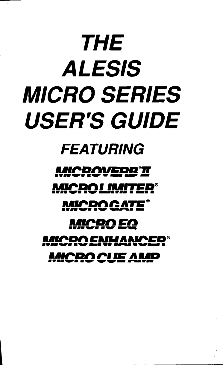

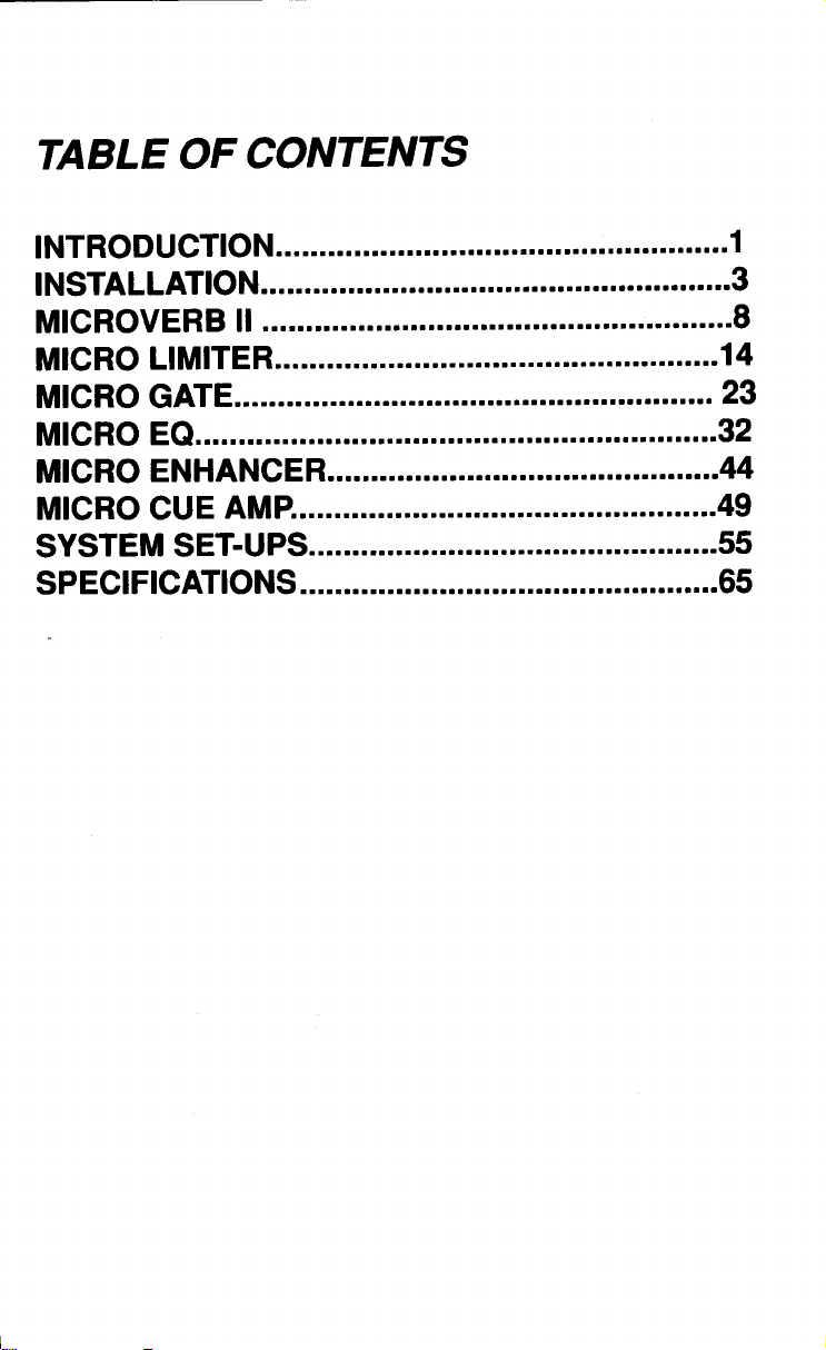
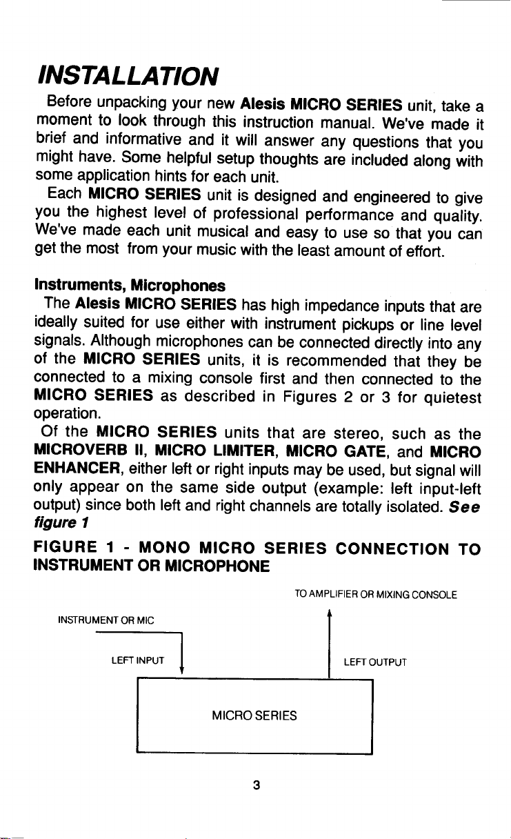
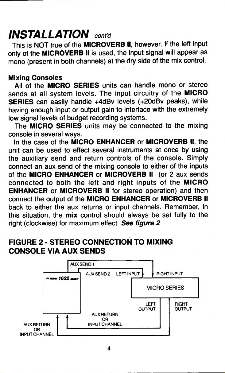
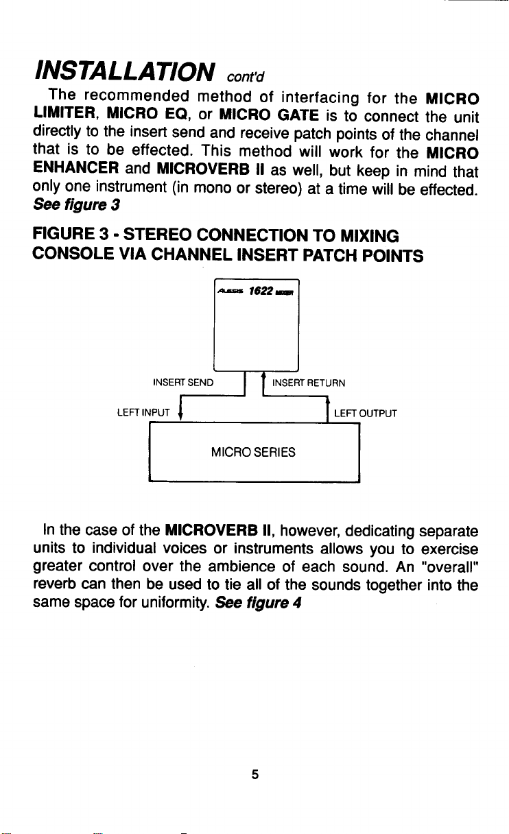
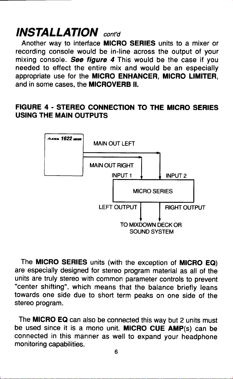

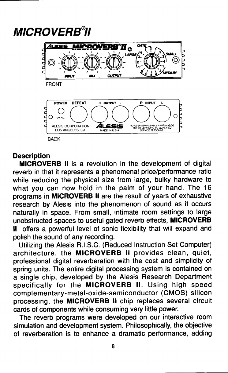

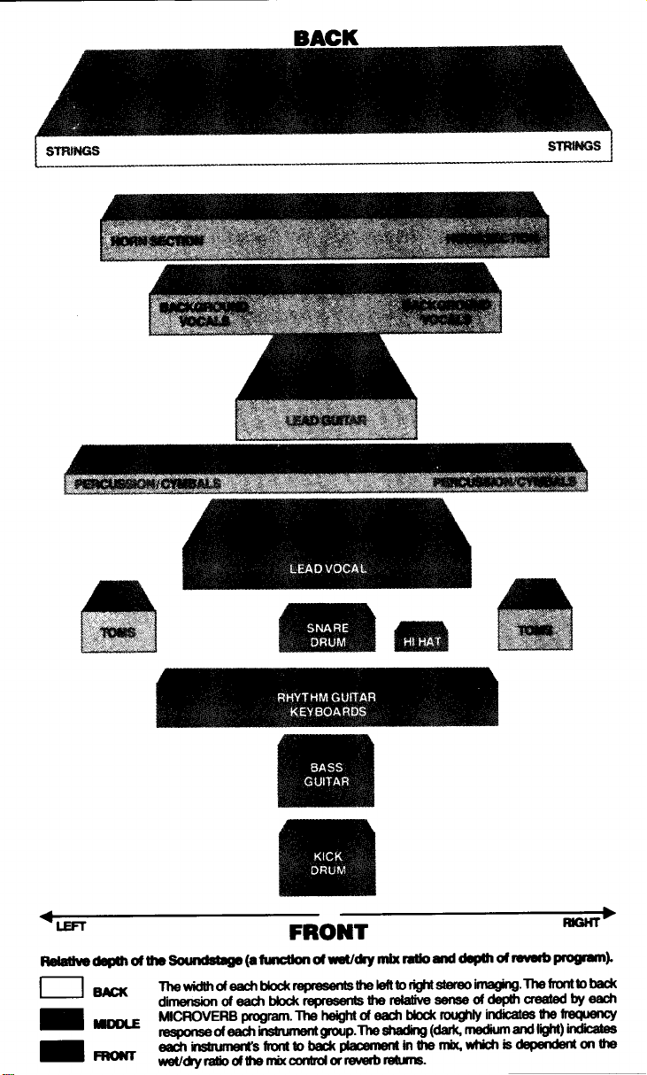
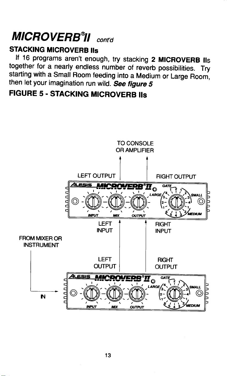
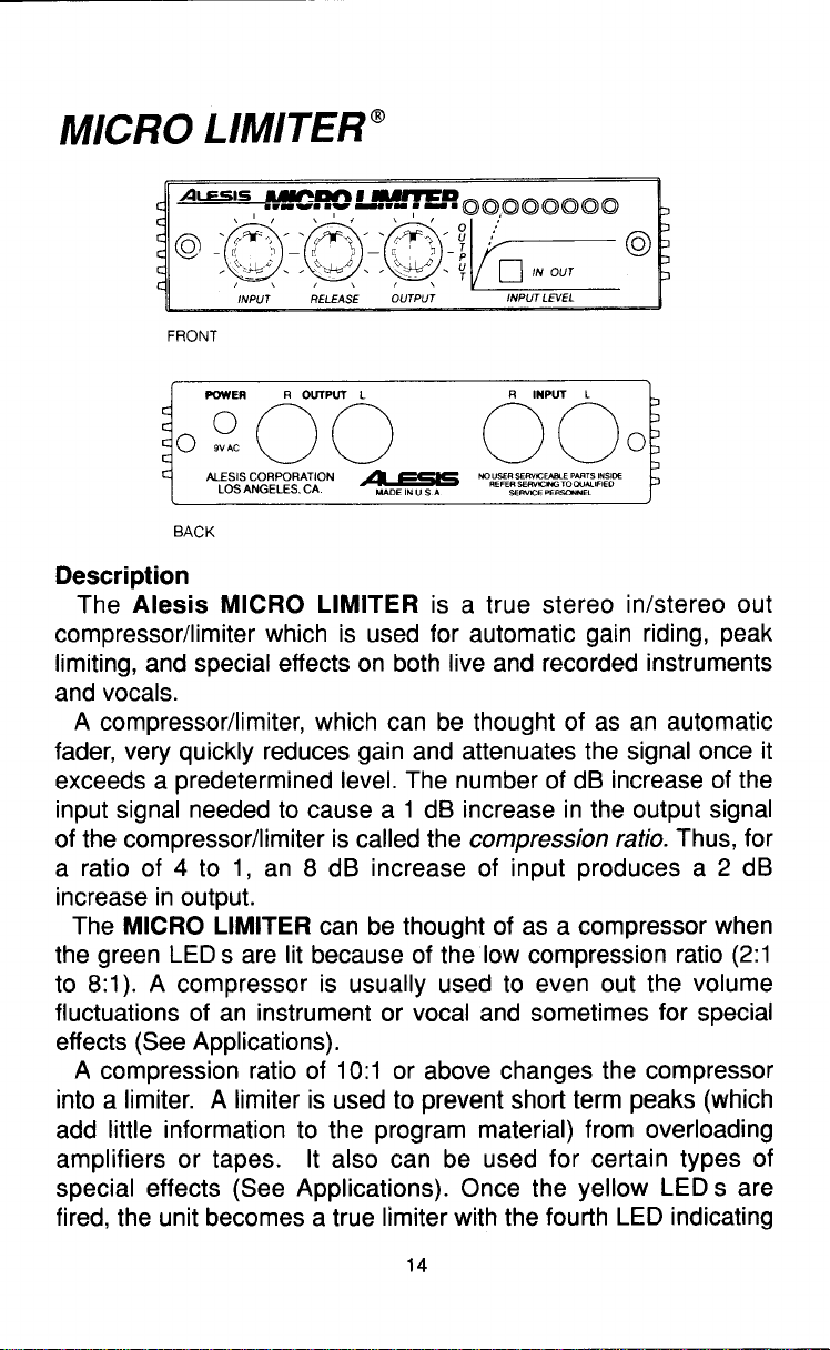
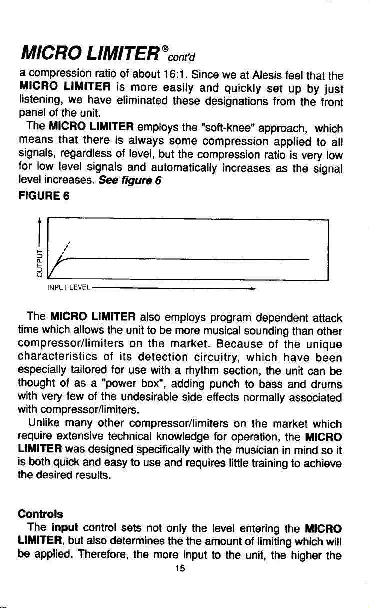


 Loading...