

Page 1

Installation
Guide:
OmniAccess
601, 602, and
604
June 2005
Page 2

Alcatel 26801 West Agoura Road Calabasas, CA 91301
818 880 3500
Copyright
Copyright © 2002-2005, Alcatel All rights reserved. No part of this documentation may be reproduced in any form or by any means without
prior written authorization from Alcatel.
Alcatel reserves the right to revise this documentation and to make changes in content from time to time without obligation to provide
notification of such changes.
Alcatel provides this documentation without warranty expressed, implied, statutory, or otherwise, and specifically disclaims any warranty of
merchantability or fitness for a particular purpose. Alcatel may make improvements or changes in the product(s) and/or the program(s)
described in this documentation at any time.
Trad em arks
Alcatel and the Alcatel corporate logo are trademarks of Alcatel All other trademarks appearing in this guide are the exclusive property of their
respective owners.
Software Notice
Alcatel assumes no responsibility for product reliability, performance, or both if the user modifies the .CFG file. Full responsibility for any
performance issues resulting from modifications made to the .CFG file, by the user, is assumed by the user.
Hardware Notice
CAUTION: To reduce the risk of fire, use only number 26 AWG or larger UL Listed or CSA Certified Telecommunication Line Cord
for all network connections.
CAUTION: Risk of explosion if battery is replaced by an incorrect type. Dispose of used batteries according to the instructions.
The Lithium battery in this product is part of a non-volatile memory device and will retain data for 10 years in the absence of power. Alcatel
does not consider the lithium battery in this unit a field replaceable or serviceable part and should not be accessed by the customer.
WARNING: Before working on this equipment be aware of good safety practices and the hazards involved with electrical circuits.
Documentation Feedback
The mission of the Technical Publications group at Alcatel is to provide quality documentation that enhances the user’s experience with Alcatel
products. We are constantly improving our guides and have a genuine interest in ensuring that our guides are easy to use and enable users to
quickly find information they need. We invite you to be part of this process; please email your comments regarding Alcatel product
documentation and web content to:
support@ind.alcatel.com
June 2005
Page 3

T
ABLE OF
Copyright ........................................................................................................................................... ii
Trademarks......................................................................................................................................... ii
Software Notice.................................................................................................................................. ii
Hardware Notice ................................................................................................................................ ii
Documentation Feedback................................................................................................................... ii
FIGURES
TABLES
1 ABOUT THIS GUIDE
Organization....................................................................................................................................... 2
Conventions ....................................................................................................................................... 3
Notices ........................................................................................................................................... 3
Documentation ................................................................................................................................... 4
About the Alcatel Router Documentation CD ............................................................................... 4
Navigation .................................................................................................................................. 4
Printing Documents.................................................................................................................... 4
Related Alcatel Guides................................................................................................................... 4
C
ONTENTS
2 PRODUCT INTRODUCTION
Overview............................................................................................................................................ 7
OmniAccess 601 ................................................................................................................................ 8
OmniAccess 601 Front Panel......................................................................................................... 8
OmniAccess 601 Back Panel ......................................................................................................... 8
OmniAccess 602 ................................................................................................................................ 10
OmniAccess 602 Front Panel......................................................................................................... 10
OmniAccess 602 Back Panel ......................................................................................................... 10
LEDs .............................................................................................................................................. 10
OmniAccess 604 ................................................................................................................................ 12
OmniAccess 604 Front Panel......................................................................................................... 12
OmniAccess 604 Back Panel ......................................................................................................... 12
LEDs .............................................................................................................................................. 12
3 INSTALLATION
Site Preparation .................................................................................................................................. 15
Environment................................................................................................................................... 15
Power Requirements ...................................................................................................................... 16
Network Connection ...................................................................................................................... 16
Cables Required ............................................................................................................................. 16
Installation Guide: 601, 602, and 604 Routers
Page 4

Tools Required ............................................................................................................................... 17
Unpacking and Inspecting .................................................................................................................. 18
Wall-Mounting Option ................................................................................................................... 19
Rack-Mounting Option .................................................................................................................. 20
Installing the OmniAccess 601, OmniAccess 602, and OmniAccess 604 Router............................ 21
Table Top Installation .................................................................................................................... 21
Wall-Mount Installation ................................................................................................................. 22
Rack-Mount Installation................................................................................................................. 24
Network Connections ......................................................................................................................... 25
Connecting the Ethernet Cable....................................................................................................... 25
Connecting the WAN Cable........................................................................................................... 25
Connecting Drop and Insert Cables ...............................................................................................26
Operator Interface .............................................................................................................................. 27
Local Management ......................................................................................................................... 27
Remote Management...................................................................................................................... 27
Console Messages .......................................................................................................................... 28
4 CONFIGURATION
Logging In .......................................................................................................................................... 29
Command Tips ............................................................................................................................... 29
Ethernet Configuration Tip ............................................................................................................ 29
Changing Login Parameters ...............................................................................................................31
Password......................................................................................................................................... 31
Administrator Account................................................................................................................... 31
System Host Name ......................................................................................................................... 32
Date and Time ................................................................................................................................ 32
Adding Users.................................................................................................................................. 33
Removing Users ............................................................................................................................. 33
Default Configuration ........................................................................................................................ 34
Configuring Drop and Insert Multiplexing ........................................................................................36
Rules............................................................................................................................................... 36
Recommendations .......................................................................................................................... 36
Examples ........................................................................................................................................ 36
E1 Configuration ........................................................................................................................ 36
T1 Configuration ........................................................................................................................ 37
Port Upgrade/Activation .................................................................................................................... 39
Installing the Software License Key .................................................................................................. 40
Switching Routing/IPMUX Modes ................................................................................................ 40
Switching to IPMux Mode .........................................................................................................40
Switching to Routing Mode .......................................................................................................40
Boot Process ....................................................................................................................................... 41
Upgrading System Software............................................................................................................... 42
Before Downloading the T1000.Z File .......................................................................................... 42
Upgrading Software ....................................................................................................................... 43
Booting From a Network TFTP Server..............................................................................................44
Interface Configuration ...................................................................................................................... 47
Bundle Configuration......................................................................................................................... 48
Routing Configuration........................................................................................................................ 50
Compact Flash Configuration ............................................................................................................ 52
Saving Configurations........................................................................................................................ 52
5 TROUBLESHOOTING
Alarms and System Status .................................................................................................................. 53
WAN Statistics ............................................................................................................................... 53
Network Tests .................................................................................................................................... 54
Ping Test......................................................................................................................................... 54
Other Tests ..................................................................................................................................... 54
Installation Guide: 601, 602, and 604 Routers
Page 5

Loopback Test............................................................................................................................ 54
BERT Test .................................................................................................................................. 54
Diagnostics Tips................................................................................................................................. 55
General Symptoms ......................................................................................................................... 55
A SPECIFICATIONS
System Specifications ........................................................................................................................ 60
WAN Interfaces ............................................................................................................................. 61
LAN Interfaces............................................................................................................................... 62
Cable Pinouts ................................................................................................................................. 63
MIBs................................................................................................................................................... 65
B COMPLIANCE AND STANDARDS
Compliance ........................................................................................................................................ 67
FCC Conformance ............................................................................................................................. 68
FCC Part 15.................................................................................................................................... 68
FCC Part 68.................................................................................................................................... 68
Incidence of Harm.......................................................................................................................... 69
Rights of the Telephone Company.................................................................................................69
Proper Disposal of Alcatel Equipment............................................................................................... 70
INDEX
CORPORATE POLICY
Standard Warranty ............................................................................................................................. 73
Hardware........................................................................................................................................ 73
Software ......................................................................................................................................... 73
Technical Support .......................................................................................................................... 73
Procedures ...................................................................................................................................... 73
Exclusions ...................................................................................................................................... 73
Non-Alcatel Products ..................................................................................................................... 73
Disclaimer of Warranty.................................................................................................................. 73
Limitation of Liability.................................................................................................................... 74
Equipment Malfunction ..................................................................................................................... 74
Contacting Alcatel.............................................................................................................................. 74
Installation Guide: 601, 602, and 604 Routers
Page 6

Page 7

F
IGURES
1 OmniAccess 601 Router Front Panel......................................................................................... 8
2 OmniAccess 601 Router Back Panel ......................................................................................... 8
3 OmniAccess 602 Router Front Panel......................................................................................... 10
4 OmniAccess 602 Router Back Panel ......................................................................................... 10
5 OmniAccess 604 Router Front Panel......................................................................................... 12
6 OmniAccess 604 Router Back Panel ......................................................................................... 12
7 Chassis Air Flow ........................................................................................................................ 15
8 Ethernet Cable............................................................................................................................ 16
9 WAN Cable................................................................................................................................ 17
10 Required Tools ........................................................................................................................... 17
11 Items Shipped with the OmniAccess 601, OmniAccess 602, and OmniAccess 604 Router.... 18
12 Wall-Mount Components...........................................................................................................19
13 Rack-Mount Components .......................................................................................................... 20
14 Table Top Installation .........................................................................................................
15 Wall Mounting the Model OmniAccess 601 Router ................................................................. 22
16 Wall Mounting the OmniAccess 602 and OmniAccess 604 Router......................................... 23
17 Rack Mounting the OmniAccess 602 and OmniAccess 604 Router ........................................ 24
18 Connecting the Ethernet Cable ................................................................................................. 25
19 Connecting the WAN Cable ..................................................................................................... 26
20 Connecting Drop and Insert Cables ........................................................................................... 26
21 Connecting the Console Cable (Local Management) ................................................................ 27
22 Connecting a Modem for Remote Management ....................................................................... 27
23 Initial CLI Prompt ...................................................................................................................... 29
....... 21
Installation Guide: 601, 602, and 604 Routers
Page 8

Page 9

T
ABLES
1 Guide Organization: Chapters..................................................................................................... 2
2 Guide Organization: Appendices ................................................................................................ 2
3 Text Conventions ........................................................................................................................ 3
4 LED and Port Descriptions ......................................................................................................... 8
5 OmniAccess 601 Back-Panel Ports............................................................................................. 9
6 LED Descriptions........................................................................................................................ 10
7 OmniAccess 602 Back-Panel Ports............................................................................................. 11
8 LED Descriptions........................................................................................................................ 12
9 OmniAccess 604 Back-Panel Ports............................................................................................. 13
10 Ethernet Interface Default Configuration ................................................................................... 34
11 IP Default Configuration............................................................................................................. 34
12 T1 Interface Default Configuration............................................................................................. 35
13 E1 Interface Default Configuration............................................................................................. 35
14 Default Console Port Settings ..................................................................................................... 35
15 Compact Flash File Commands .................................................................................................. 52
16 BERT Test Patterns..................................................................................................................... 54
17 Common Symptoms and Actions ............................................................................................... 55
18 Environment, Hardware, Memory, and Power ........................................................................... 60
19 Performance Monitoring ............................................................................................................. 61
20 T1 WAN Interface ...................................................................................................................... 61
21 E1 WAN Interface ...................................................................................................................... 62
22 Specifications: Ethernet LAN Interface ...................................................................................... 62
23 Miscellaneous.............................................................................................................................. 62
24 Pinouts: Alcatel-to-Terminal Console Cable (DB-9).................................................................. 63
25 Pinouts: Ethernet Cable (RJ-45) .................................................................................................63
26 Pinouts: WAN Cable (RJ-48C)................................................................................................... 63
27 DB-25 to RJ-45 Modem Adapter Pinouts................................................................................... 64
28 Standard MIBS............................................................................................................................ 65
29 Alcatel Enterprise MIBs.............................................................................................................. 66
30 Regulatory and Compliance Standards ....................................................................................... 67
Installation Guide: 601, 602, and 604 Routers
Page 10

Page 11

1
A
BOUT
Detailed instructions are provided in this guide for installing, configuring, and
troubleshooting the Alcatel OmniAccess 601, OmniAccess 602, and OmniAccess 604 router.
This guide is designed for network managers, administrators, and technicians who are
responsible for the installation and management of networking equipment in Enterprise
and Service Provider environments. Knowledge of Telecom technologies and standards
including T1, E1, and Ethernet is assumed.
This chapter provides information about the intended audience for this guide, how this
guide is organized, typographical conventions, the use of notices, and related
documentation.
T
HIS
G
UIDE
1
Installation Guide: 601, 602, and 604 Routers
Page 12

2
CHAPTER
1
About This Guide Organization
Organization
The following tables describe the content and organization of this guide.
Table 1 Guide Organization: Chapters
Chapter Description
1 About This Guide - defines the user audience, and describes the organization of this guide, use of
special notices, and other Alcatel user guides.
2 Product Introduction - provides a description of installation site requirements, and cables and
tools required for installing the Alcatel OmniAccess 601, OmniAccess 602, and OmniAccess
604 router.
3 Installation - describes the system front and back panels and how to install the Alcatel
4 Configuration - describes system configuration, logging in, factory defaults, changing the default
5 Troubleshooting - provides information about network indicators, tests, and general
OmniAccess 601, OmniAccess 602, and OmniAccess 604 router. Information is also provided
about the operator interface, network cabling, and the operator interface.
password, upgrading software, and the boot process.
troubleshooting tips. A summary of common problems and solutions is also included.
Table 2 Guide Organization: Appendices
Appendix Description
A Specifications - lists the electrical, physical, and networking characteristics of the Alcatel
OmniAccess 601, OmniAccess 602, and OmniAccess 604 router. Cable pinout and related MIB
file information is also provided.
B Compliance and Standards - provides regulatory information and compliance information
applicable to the Alcatel OmniAccess 601, OmniAccess 602, and OmniAccess 604 router.
Installation Guide: 601, 602, and 604 Routers
Page 13

Conventions
Notices
This guide uses the following typographical conventions:
Table 3 Text Conventions
Font Description
boldface font
screen font
Used for commands that you enter, words that you type, or keyboard keys that you press.
Used to display a screen capture.
Notice paragraphs alert you about issues that require your attention. The following paragraphs
describe the types of notices used in this guide.
NOTE: Notes provide tips and useful information regarding the installation and operation of Alcatel
systems.
ESD: ESD notices provide information about how to avoid discharge of static electricity and subsequent
damage to Alcatel systems.
3
CAUTION: Caution notices provide information about how to avoid possible service disruption or
damage to Alcatel systems.
WARNING: Warning notices provide information about how to avoid personal injury when working
with Alcatel systems.
Installation Guide: 601, 602, and 604 Routers
Page 14

4
CHAPTER
1
About This Guide Documentation
Documentation
Alcatel user guides, which are provided in portable document format (PDF), are included on
the Alcatel Router Documentation CD-ROM that ships with the OmniAccess 601, OmniAccess
602, and OmniAccess 604 router. The PDF files are also available on the Alcatel website:
http://eservice.ind.alcatel.com.
To view PDF files, Adobe Acrobat® Reader® 4.0, or newer, must be installed on your
workstation. If you do not have the Adobe Acrobat Reader installed on your system, you can
obtain it free from the Adobe website: www.adobe.com
About the Alcatel Router Documentation CD
This product ships with a CD that includes the following documentation:
Quick Start Guide: OmniAccess 600-series Routers
Installation Guide: OmniAccess 600-series Routers
Command Reference Guide
Router User Guide
Configuration Guide
Device Manager Web Interface User Guide
Supported standard and enterprise MIBs
Feature summaries
SNMP trap descriptions with default configurations
.
Related Alcatel Guides
Navigation
Upon inserting the Alcatel Router Documentation CD into your CD-ROM drive. Click a link to
open a pdf version of the target document. If you do not have Adobe Acrobat (version 4.0, or
later) or Acrobat Reader installed on your PC, click the Adobe button on the navigation screen
to go to the Adobe website, where you can download a free copy of the Acrobat Reader
application.
If a browser session is not opened, click “Start\Run,” enter the drive letter of your CD-ROM
drive in the “Open” entry box, and click “OK.”
Printing Documents
To print any pdf document on the CD, follow this procedure.
1 Open the desired document by clicking the document link in the CD navigation window.
2 Click the “Printer” icon on the Adobe Acrobat tool bar.
3 In the “Windows Print” dialog box, select a local default printer in the “Printers” drop
down selection box.
4 Click “OK.”
In addition to this guide, the following list includes other available Alcatel documentation:
Release Notes
Printed release notes provide the latest information. If release notes are provided
with your product, follow these instructions in addition to those provided in other
documentation.
Quick Start Guide: OmniAccess 600-series Routers
This guide is designed to assist users with the initial installation and deployment of
the Alcatel Model OmniAccess 601, OmniAccess 602, and Model OmniAccess 604
router. The guide provides a brief overview of the installation and initial configuration
processes for the Model OmniAccess 601, OmniAccess 602, and Model OmniAccess 604.
Installation Guide: 601, 602, and 604 Routers
Page 15

Command Reference Guide
This detailed guide provides a complete description of all Alcatel command line
interface (CLI) commands.
Router User Guide
This guide provides descriptions of commands available for Alcatel implementation of
BGP (including BGP4), OSPF, RIP and other routing protocols.
Configuration Guide
This guide provides example configurations.
Device Manager Web Interface User Guide
This guide explains how to configure the OmniAccess 600-series Alcatel router using
the WebUI.
5
Installation Guide: 601, 602, and 604 Routers
Page 16

Page 17

Overview
2
P
RODUCT INTRODUCTION
This chapter provides information about the Alcatel OmniAccess 601, OmniAccess 602, and
OmniAccess 604 router front and back panels, LEDs, cable connection ports, and panel
components.
This section describes front- and back-panel components of the Alcatel OmniAccess 601,
OmniAccess 602, and OmniAccess 604 router. Additional information is also provided in
following sections about external cables, wiring, and connection points.
The Alcatel OmniAccess 601, OmniAccess 602, and OmniAccess 604 are designed to provide
WAN-to-LAN networking connectivity for branch office communication and primary Internet
access for medium-size businesses. The OmniAccess 601, OmniAccess 602, and OmniAccess
604 are T1/E1 routers providing one, two, or four WAN ports, two 10/100 Fast Ethernet ports,
an AUX port, an ISDN backup port, and a local/remote management Console port.
7
The routers may be purchased with 1 to 4 ports active. If all the WAN ports are not all
activated at the time of purchase then additional ports can be activated via a software license
key. Software licence keys may be purchased to activate additional WAN ports to allow
scalable bandwidth as your needs grow. Contact Alcatel sales (1-818 880 3500) for more
information.
In addition to the command line interface, the Model OmniAccess 600-series routers support a
Web User Interface which can be used to configure basic operational and security features. For
more information on the Web UI, refer to the OmniAccess 600-series Router Web User
Interface User Guide.
Installation Guide: 601, 602, and 604 Routers
Page 18
8
CHAPTER
2
Product Introduction OmniAccess 601
OmniAccess 601
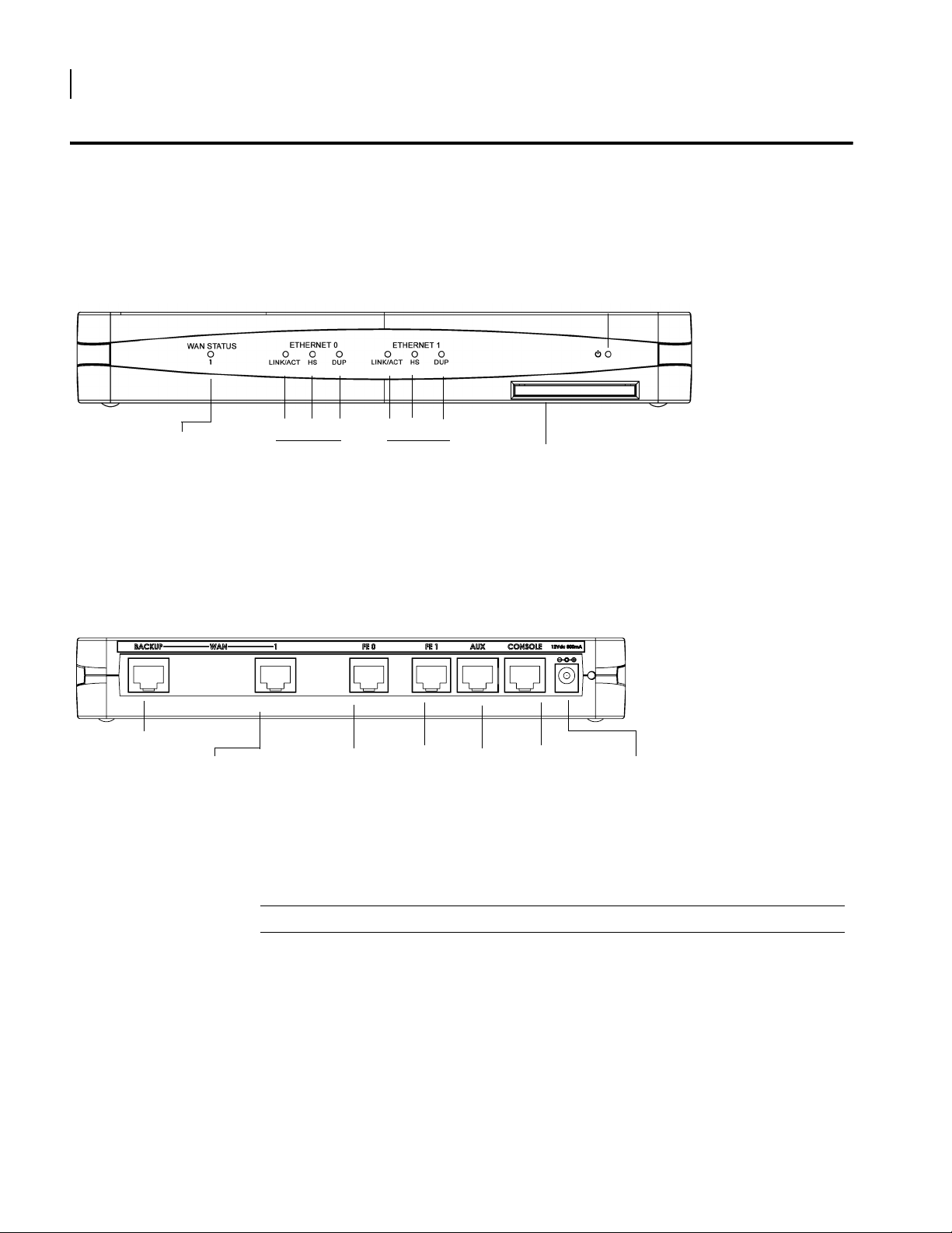
OmniAccess 601 Front Panel
The router front panel houses the system LEDs.
Figure 1 OmniAccess 601 Router Front Panel
Power LED
WA N Por t
LED
LINK/ACT HS
Ethernet 0 LEDs Ethernet 1 LEDs
OmniAccess 601 Back Panel
The OmniAccess 601 router back panel provides connections for one WAN port, two 10/100
Base-T Ethernet ports, one AUX port, one Console port, and a 12 VDC power input jack.
Figure 2 OmniAccess 601 Router Back Panel
Backup WAN Port
WA N Por t
The OmniAccess 601 front-panel LEDs indicate real-time unit status. Table 4 provides
information about how to interpret the LED states.
DUP
Fast Ethernet
Port 0
LINK/ACT HS
Fast Ethernet
Port 1
DUP
AUX Port
Compact Flash
Console
Port
12 VDC
Input Jack
Table 4 LED and Port Descriptions
Port Description Color
WAN STATUS 1 Indicates traffic activity
ETHERNET 0 / 1
Installation Guide: 601, 602, and 604 Routers
on this interface
LINK/ACT Indicates traffic activity
on this interface
HS Indicates traffic speed
on the interface
Green = normal activity
Red = alarm state
Yellow = test mode
Green = link is operational
Blinking Yellow = either receiving or sending
traffic
Red = packet collisions
Off = 10 Mbps
Green = 100 Mbps
Page 19

Table 4 LED and Port Descriptions (continued)
Port Description Color
DUP Indicates the type of
duplex mode
Power Indicates system power
status
Compact Flash Port for compact flash
Off = Half duplex
Green = Full duplex
Green = power on
Off = power off
—
module
Table 5 OmniAccess 601 Back-Panel Ports
Connector Description
WAN 1 WAN connection port. This port accepts cables with RJ-48C connectors.
Backup WAN An ISDN backup option is supported in releases 8.3 and higher. This option
provides a backup if the primary network connection is lost. This port
accepts cables with RJ-45 connectors.
FE 0 / 1 Ethernet LAN connection ports. These ports accept cables with RJ-45
cable connectors.
AUX Reverse telnet connection. This port accepts a cable with an RJ-45 cable
connector.
Console Console management port. This port accepts a cable with an RJ-45 cable
connector.
DC power 12 VDC power connection. This port accepts the 2 mm. power connector
on the DC power supply cable that ships with the OmniAccess 602 router.
9
Installation Guide: 601, 602, and 604 Routers
Page 20
OmniAccess 602
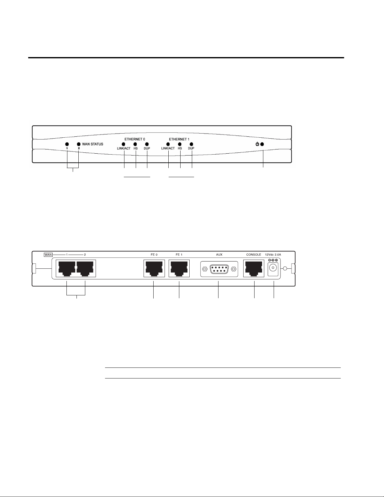
OmniAccess 602 Front Panel
The router front panel houses the system LEDs.
Figure 3 OmniAccess 602 Router Front Panel
WAN Port
LEDs 1-2
LINK/ACT HS
OmniAccess 602 Back Panel
The OmniAccess 602 router back panel provides connections for two WAN ports, two 10/100
Base-T Ethernet ports, one AUX port, one Console port, and a 12 VDC power input jack.
Figure 4 OmniAccess 602 Router Back Panel
WAN Ports 1 - 2 Fast Ethernet
LEDs
The OmniAccess 602 front-panel LEDs indicate real-time unit status. Table 6 provides
information about how to interpret the LED states.
DUP LINK/ACT HS
Ethernet 0 LEDs Ethernet 1 LEDs
Port 0
Fast Ethernet
Port 1
DUP
AUX Port
Console
Port
Power LED
12 VDC
Input Jack
Table 6 LED Descriptions
Port Description Color
WAN STATUS 1/ 2 Indicates traffic activity
on this interface
Green = normal activity
Red = alarm state
Yellow = test mode
ETHERNET 0 / 1
LINK/ACT Indicates traffic activity
on this interface
Green = link is operational
Blinking Yellow = either receiving or sending
traffic
Red = packet collisions
Page 21

Table 6 LED Descriptions (continued)
Port Description Color
HS Indicates traffic speed
on the interface
DUP Indicates the type of
duplex mode
Power Indicates system power
status
Table 7 OmniAccess 602 Back-Panel Ports
Off = 10 Mbps
Green = 100 Mbps
Off = Half duplex
Green = Full duplex
Green = power on
Off = power off
Connector Description
WAN 1 - WAN 2 WAN connection ports. These ports accept cables with RJ-48C
connectors.
FE 0 / 1 Ethernet LAN connection ports. These ports accept cables with RJ-45
cable connectors.
AUX Reverse telnet connection. This port accepts a cable with a male DB-9
connector.
Console Console management port. This port accepts a cable with an RJ-45 cable
connector.
DC power 12 VDC power connection. This port accepts the 2 mm. power connector
on the DC power supply cable that ships with the OmniAccess 602 router.
11
Installation Guide: 601, 602, and 604 Routers
Page 22
12
CHAPTER
2
Product Introduction OmniAccess 604
OmniAccess 604
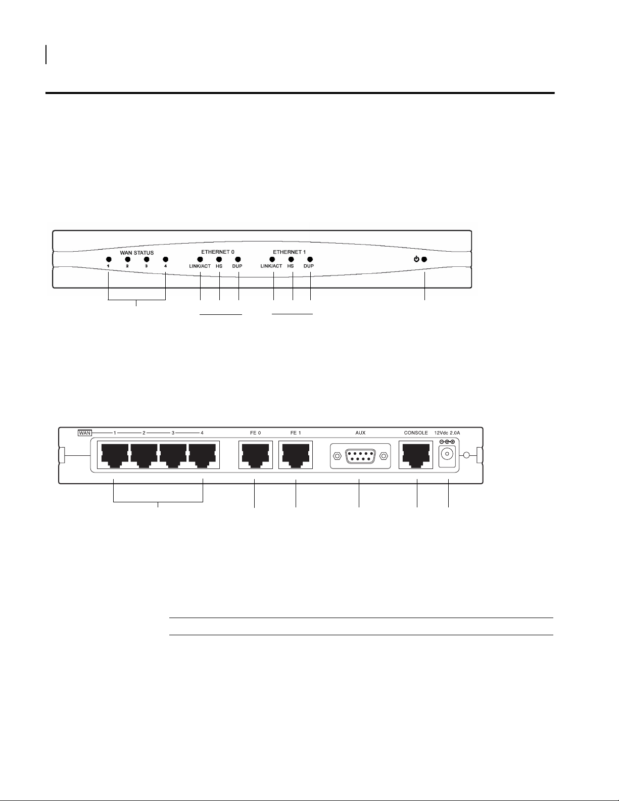
OmniAccess 604 Front Panel
The router front panel houses the system LEDs.
The following section identifies and describes the OmniAccess 604 router network ports and
LEDs.
Figure 5 OmniAccess 604 Router Front Panel
WAN Port
LEDs 1-4
LINK/ACT HS
OmniAccess 604 Back Panel
The OmniAccess 604 router back panel provides connections for four WAN ports, two 10/100
Base-T Ethernet ports, one AUX port, one Console port, and a 12 VDC power input jack.
Figure 6 OmniAccess 604 Router Back Panel
WAN Ports 1 - 4 Fast Ethernet
LEDs
The OmniAccess 604 front-panel LEDs indicate real-time unit status. Table 8 provides
information about how to interpret the LED states.
Ethernet 0 LEDs
DUP
Port 0
LINK/ACT HS
Ethernet 1 LEDs
Fast Ethernet
Port 1
DUP
AUX Port
Power LED
Console
Port
12 VDC
Input Jack
Table 8 LED Descriptions
Port Description Color
WAN STATUS 1-4 Indicates traffic activity on
ETHERNET 0/1
Installation Guide: 601, 602, and 604 Routers
this interface
Green = normal activity
Red = alarm state
Yellow = test mode
Page 23

Table 8 LED Descriptions (continued)
Port Description Color
LINK/ACT Indicates traffic activity on
this interface
Green = link is operational
Blinking Yellow = either receiving or sending
traffic
Red = packet collisions
HS Indicates traffic speed on
the interface
DUP Indicates the type of duplex
mode
Power Indicates system power
status
Off = 10 Mbps
Green = 100 Mbps
Off = Half duplex
Green = Full duplex
Green = power on
Off = power off
Table 9 OmniAccess 604 Back-Panel Ports
Connector Description
WAN 1 - WAN 4 WAN connection port. These ports accept cables with RJ-48C connectors.
If drop and insert is configured, then ports 1 and 2 are reserved for that
feature.
FE 0 - FE 1 Ethernet LAN connection ports. These ports accept cables with RJ-45 cable
connectors.
AUX Reverse telnet connection. This port accepts a cable with a male DB-9
connector.
Console Console management port. This port accepts a cable with an RJ-45 cable
connector.
DC power 12 VDC power connection. This port accepts the 2 mm. power connector
on the DC power supply cable that ships with the OmniAccess 604 router.
13
Installation Guide: 601, 602, and 604 Routers
Page 24

Page 25

Site Preparation
3
I
NSTALLATION
This chapter describes how to install and prepare the Alcatel OmniAccess 601, OmniAccess
602, and OmniAccess 604 router for operation. Information is also provided describing the
system front and back panels, operator interface, how to mount the chassis, and how to
connect network and power cables.
Before you install the OmniAccess 601, OmniAccess 602, and OmniAccess 604, familiarize
yourself with the network interface and power connections described in this chapter.
Before installing a Alcatel OmniAccess 601, OmniAccess 602, and OmniAccess 604 router,
ensure that the site conditions comply with the following requirements and that the mounting
equipment, tools, and cables are available at the installation site.
15
Environment
Site location is important for the proper operation of the OmniAccess 601, OmniAccess 602,
and OmniAccess 604 router. Place the unit in a clean, dry environment with adequate air
circulation. Allow additional clearance around the system for foot traffic and access to cable
connectors on the rear panel.
Figure 7 shows the convection cooling vents on top of the unit. To prevent an
over-temperature condition, which could result in system failure or performance degradation,
make sure that these vents are not obstructed.
NOTE: In normal operation, the router will be “warm to the touch.”
Figure 7 Chassis Air Flow
CAUTION:
of the router and such action could lead to equipment damage.
Refer to Appendix A for more information about environmental requirements.
Do not stack routers on top of each other. Doing so will defeat the convection cooling ability
Installation Guide: 601, 602, and 604 Routers
Page 26

16
CHAPTER
Installation Site Preparation
3
Power Requirements
The OmniAccess 601, OmniAccess 602, and OmniAccess 604 router operates on 12 VDC power.
A 12 VDC power supply and an AC power cord are shipped with the router.
Network Connection
To successfully complete the installation, the router must be connected to a network. Before
you start the installation, make sure that a live network connection is available at the
installation site.
Cables Required
The OmniAccess 601, OmniAccess 602, and OmniAccess 604 router ships with a Console cable.
You will need to obtain additional cables for your specific application. The following additional
cables are required to install the OmniAccess 601, OmniAccess 602, and OmniAccess 604
router.
One or two RJ-45, male/male, category 5, 26 AWG (minimum), twisted-pair,
straight-through cable (Ethernet LAN connection)
See Table 25 on page 63 for cable pinout information.
Refer to Figure 8 on page 16 to identify this cable.
Figure 8 Ethernet Cable
One or two RJ-48C, male/male, category 5, 26 AWG (minimum), twisted-pair,
straight-through WAN cable
See Table 26 on page 63 for cable pinout information.
Refer to Figure 9 to identify this cable.
Installation Guide: 601, 602, and 604 Routers
Page 27

Tools Required
17
Figure 9 WAN Cable
The following tools are required to install the Alcatel OmniAccess 601, OmniAccess 602, and
OmniAccess 604 router.
Figure 10 Required Tools
#2 Phillips screwdriver
#3 Phillips screwdriver 1/4 inch flat blade screwdriver
Installation Guide: 601, 602, and 604 Routers
Page 28

18
CHAPTER
Installation Unpacking and Inspecting
3
Unpacking and Inspecting
After opening the shipping carton, remove and save all packing materials and boxes.
NOTE: Save the packing materials. If you need to return the product, you will need to repack the unit
with the original packing material. See the Procedures section in Standard Warranty on page 73 for
details about product returns.
Check the packing slip and contents of the shipping carton to ensure that you have
received the following items.
Figure 11 Items Shipped with the OmniAccess 601, OmniAccess 602, and OmniAccess 604 Router
Alcatel router (OmniAccess 604 shown) Quick Start Guide, CD ROM, product information
Power supply for OmniAccess 602 and
OmniAccess 604 - OmniAccess 601 power supply
plugs directly into an AC outlet
AC power cord Female Console cable to PC adapter
RJ-45 Console cable
Installation Guide: 601, 602, and 604 Routers
Power supply cord retainer bracket Male DB-25 modem adapter
Page 29

Wall-Mounting Option
1
19
Inspect the OmniAccess 601, OmniAccess 602, and OmniAccess 604 and the shipping carton for
damage that may have occurred during shipping. If you discover damage or that items are
missing, contact Alcatel Technical Support. Refer to the Alcatel website for contact
information: http://eservice.ind.alcatel.com.
An optional wall-mounting assembly is available for mounting the OmniAccess 601,
OmniAccess 602, and OmniAccess 604 router on a vertical surface. The wall-mount
components are shipped in the same box with the OmniAccess 601, OmniAccess 602, and
OmniAccess 604 router, and are shown in the following figure:
Figure 12 Wall-Mount Components
OmniAccess 602 and OmniAccess 604
Wall-mount bracket
Power supply strap
Hollow wall anchors Wall-mount screws: (4) 6 x 1 inch Phillips pan head
Router to wall-mount bracket screws: (4) 4-40 x .250 inch
Phillips pan head
OmniAccess 60
Installation Guide: 601, 602, and 604 Routers
Page 30

20
CHAPTER
3
Installation Unpacking and Inspecting
Rack-Mounting Option
An optional rack-mounting tray is available for installing two Model OmniAccess 602 or Model
OmniAccess 604 routers in an equipment rack. The following items are shipped in a separate
carton:
Figure 13 Rack-Mount Components
Rack Tray
2) Mounting Brackets
4) 10-24 x .5 Phillips Pan
Head Screws for
Equipment Rack
(4) Velcro Tie Wraps
(4) 10-24 x .5 Phillips Pan
Head Screws for
Equipment Rack
(2) Rack Carriage Assemblies
(2 sets) Velcro Mounting Pads
(6) 6-32 x .25 Phillips Flat
Head Mounting Bracket
Screws
4) 4-40 x .25 Phillips Pan
Head Rack Carriage Screws
Installation Guide: 601, 602, and 604 Routers
Page 31

Installing the OmniAccess 601, OmniAccess 602, and OmniAccess 604 Router
The OmniAccess 601, OmniAccess 602, and OmniAccess 604 router can be installed on a table
top, in a Telco equipment rack (using the optional rack-mounting tray), or on a vertical surface
(using the optional wall-mounting assembly). The router ships with a Console cable. You will
need to obtain additional cables for your specific application. Refer to Figure 8 and Figure 9.
The illustrations in this section use a Model OmniAccess 602 to show how the router is
connected. The backplanes for the Model OmniAccess 601 and Model OmniAccess 604 are
slightly different but use the same port labeling conventions. If you don’t see the port
identified in an illustration below, refer to the backplane illustration for your router model in
Product Introduction.
CAUTION: Do not block the cooling vents on the top of the unit.
NOTE: For problem-free operation, the router should be located in an area with adequate ventilation.
Table Top Installation
To install the OmniAccess 601, OmniAccess 602, and OmniAccess 604 for operation on a table
top, follow this procedure. Refer to Figure 14 (which shows a Model OmniAccess 602).
Figure 14 Table Top Installation
21
110/120 VAC Outlet
Threaded Hole
12 VDC Port
Cable Retainer
1 Place the unit on the table surface.
2 Insert the DC power cable into the DC input jack on the front of the unit.
3 Attach the cable retainer bracket behind the molded strain relief on the power supply
cable near the DC input jack.
4 Engage and secure the captive screw on the retainer in the threaded hole adjacent to the
input jack on the router.
5 Connect the appropriate ends of the AC power cord to the power supply and a
110/120 VAC outlet.
NOTE: Ensure that the cables are router out of the way of foot traffic.
Installation Guide: 601, 602, and 604 Routers
Page 32

22
CHAPTER
Installation Installing the OmniAccess 601, OmniAccess 602, and OmniAccess 604 Router
3
Wall-Mount Installation
Follow this procedure to attach the Alcatel OmniAccess 601, OmniAccess 602, and OmniAccess
604 router to a vertical surface.
Figure 15 Wall Mounting the Model OmniAccess 601 Router
Installation Guide: 601, 602, and 604 Routers
Page 33

Figure 16 Wall Mounting the OmniAccess 602 and OmniAccess 604 Router
23
1 Attach the router to the wall mount assembly using four (provided) Phillips pan head 4-40
x .250 inch screws.
Ensure that the router is oriented in a manner that allows the LEDs to be visible.
2 Attach the assembly with the mounted router to the wall surface with four (provided) 6 x
1 inch (for OmniAccess 602 and OmniAccess 604) or 4 x 1 (for OmniAccess 601) Phillips pan
head screws and hollow wall plastic anchors.
NOTE: The provided hollow wall anchors are not designed for installation in hard walls. These anchors
should only be installed in a sheet rock (gypsum wall board) wall.
3 Fit the AC strap over the power supply and then place the power supply on the wall mount
bracket within the four locating tabs.
4 Engage and tighten the AC strap captive screw to secure the power supply to the wall
mount assembly.
5 Attach the cable retainer to the DC power cord behind the molded strain relief on the
cable.
6 Insert the DC power cable jack into the 12 VDC port on the back of the router.
7 Engage and tighten the captive screw on the cable retainer in the threaded hole adjacent
to the DC input jack on the router.
8 Connect the appropriate ends of the AC cord to the secured power supply and a 110/120
VAC o u tl e t .
Installation Guide: 601, 602, and 604 Routers
Page 34

24
CHAPTER
Installation Installing the OmniAccess 601, OmniAccess 602, and OmniAccess 604 Router
3
Rack-Mount Installation
To mount the OmniAccess 602, and OmniAccess 604 in an equipment rack, follow this
procedure. (This procedure does not apply to the Model OmniAccess 601.) Refer to Figure 17.
Figure 17 Rack Mounting the OmniAccess 602 and OmniAccess 604 Router
1 Determine the mounting position for the rack tray in the equipment rack (front or mid
mount) and attach the mounting brackets using the four (provided) 6-32 x .250 inch flat
head Phillips screws.
2 Attach the router to the carriage assembly using four (provided) Phillips pan head 4-40 x
.250 inch screws.
3 Engage the carriage assembly in the rack tray rails and slide the assembly all the way in.
4 Fit the AC strap over the power supply and then place the power supply on the rack tray
between the raised tab and the back edge of the tray.
5 Engage and tighten the AC strap captive screw to secure the power supply to the rack
tray.
6 Attach the cable retainer bracket to the DC power cord behind the molded strain relief on
the cable.
7 Insert the power cable jack into the 12 VDC port on the back of the router.
8 Engage and tighten the captive screw on the cable retainer bracket in the threaded hole
adjacent to the DC input jack on the router.
9 Coil the excess cable and secure it on the tray behind the router.
10 Mount the tray in the equipment rack using either four (provided) Phillips pan head 10-24
x .5 inch screws or four (provided) Phillips pan head 12-32 x .5 inch screws, whichever fits
the equipment rack.
11 Connect the network cables to the router. Secure the cables in the clips located on the
bottom of the carriage assembly. Refer to Network Connections on page 25.
12 Connect the appropriate ends of the AC cord to the secured power supply and a 110/120
VAC o ut l et .
13 Using a small flat blade screwdriver, engage and tighten the captive screw to secure the
carriage assembly to the rack tray.
Installation Guide: 601, 602, and 604 Routers
Page 35

Network Connections
The following sections describe how to connect various network cables to the Alcatel
OmniAccess 601, OmniAccess 602, and OmniAccess 604 router.
Connecting the Ethernet Cable
The front panel on the router accommodates one LAN connections. Use a category 5,
twisted-pair Ethernet cable with RJ-45 connectors to connect to the LAN. Refer to Figure 8 on
page 16 to identify this cable.
Follow this procedure to connect the OmniAccess 601, OmniAccess 602, and OmniAccess 604
to an Ethernet LAN network.
1 Connect the RJ-45 connector of a category 5 rated Ethernet cable to either the Ethernet 0
or Ethernet 1 port on the back panel.
2 Connect the RJ-45 connector on the other end of the cable to the LAN port.
Make sure that the cable connectors are locked and secure in the ports. See Table 25 on page
63 for pinout information about this cable.
Figure 18 Connecting the Ethernet Cable
25
Connecting the WAN Cable
The back panel accommodates up to two WAN (model specific) cables. Use 26 AWG (minimum)
category 5, twisted-pair cable with RJ-48C connectors for this interface. Refer to Figure 9 on
page 17 to identify this cable.
Follow this procedure to connect a WAN port to the network:
1
2 Insert the RJ-48C connectors on the other ends of the cables in the WAN ports on the front
Ethernet LAN Port
Fast Ethernet Port 0
CAUTION: To reduce the risk of fire, use only number 26 AWG or larger UL Listed or CSA Certified
Telecommunication Line Cord for all network connections.
Insert the RJ-48C connectors on one end of one cable in the appropriate port on the
Service Provider’s demarcation point.
panel of the Alcatel router.
Fast Ethernet Port 1
Make sure that the cable connectors are locked and secure in the ports. See Table 26 on page
63 for pinout information about this cable.
Installation Guide: 601, 602, and 604 Routers
Page 36

26
CHAPTER
3
Installation Network Connections
Figure 19 Connecting the WAN Cable
Connect to Service
Provider’s Demarcation
Point
WAN Port 1
Figure 19 shows the WAN cabling for a Model OmniAccess 602. A Model OmniAccess 601 only
has one WAN port. A Model OmniAccess 604 has four WAN ports.
Connecting Drop and Insert Cables
WAN ports 1 and 2 can alternatively be used for drop and insert traffic. Port 1 is designated for
voice; port 2 is used for data traffic. Use two 26 AWG (minimum) category 5, twisted-pair
cables with RJ-48C connectors to establish this connectivity.
Figure 20 Connecting Drop and Insert Cables
Connect to the Local PBX Port
Connect to Service Provider’s
Demarcation Point
RJ-48C WAN Cables
To connect drop and insert cables, follow this procedure. Refer to Figure 20.
1 Insert the RJ-48C connector of one end of one WAN cable in WAN port 1 on the router.
2 Connect the other end of this cable to the local PBX port.
3 Insert the connector on one end of the second cable to WAN port 2 on the router.
4 Connect the other end of this cable to the Service Provider’s demarcation point.
For information about configuring drop and insert, refer to the Command Reference Guide.
Installation Guide: 601, 602, and 604 Routers
Page 37

Operator Interface
Local Management
The OmniAccess 601, OmniAccess 602, and OmniAccess 604 can be locally configured,
operated, and managed using an operator console connected to the Console port. A terminal
(VT-100 or equivalent) or workstation with terminal emulation software can be used for the
operator console. Connect the console to the OmniAccess 601, OmniAccess 602, and
OmniAccess 604 router Console port using an RJ-45 cable with switched ends. If your terminal
equipment requires a special cable, see Table 24 on page 63 for connector pinout information.
To connect the Console cable:
Connect the RJ-45 Console cable to the Console port on the router.
1
2 Connect the other end of the RJ-45 Console cable to the RJ-45 end of the adapter.
3 Connect the DB-9 end on the adapter to the management terminal or workstation.
Figure 21 Connecting the Console Cable (Local Management)
RJ-45 to DB-9 Adapter
27
Remote Management
Console Port
A modem can be connected to the Console port and used to configure, operate, and manage
the OmniAccess 601, OmniAccess 602, and OmniAccess 604 remotely.
Figure 22 Connecting a Modem for Remote Management
DB-25 Modem Adapter
Modem
Console Port
Installation Guide: 601, 602, and 604 Routers
Page 38

Console Messages
Follow this procedure to connect the OmniAccess 601, OmniAccess 602, and OmniAccess 604
to a modem. Refer to Figure 22.
1 Connect the male end of the DB-25 adapter to the female DB-25 port on the modem.
2 Connect one end of a supplied RJ-45 cable to the RJ-45 port in the DB-25 adapter.
3 Connect the other end of the RJ-45 cable to the Console port on the OmniAccess 601,
OmniAccess 602, and OmniAccess 604.
4 Refer to the Alcatel Support website for modem configuration information.
If a workstation is used for the remote management console, use VT-100 terminal emulation
software or equivalent, and configure the software as specified for modems.
Alarm messages are displayed at the console when system logging is configured. Refer to the
configure system logging console command and related system logging commands in the
Command Reference Guide for more information about how to configure specific alarm
events.
For more information about command usage for T1 products, refer to the Command Reference
Guide. These guides are available on the Alcatel website:http://eservice.ind.alcatel.com.
Page 39

Logging In
4
C
ONFIGURATION
This chapter describes how to login; change the default password, configure the router and
users, and change the factory default configuration. The boot process and software upgrade
process is also discussed in detail.
If you have not established a local console connection, see Operator Interface on page 27 for
more information.
The following figure shows the login sequence and the initial prompt after login is complete.
29
Command Tips
Figure 23 Initial CLI Prompt
login: username
password:
username logged in on Fri August 6 05:28:01 2004
from console
Initial CLI Prompt
NOTE: The default host name is Alcatel.
Use the following command tips and shortcuts with command line interface commands.
To display all commands, type tree.
To access help associated with a command, type help <command name>. You may also use
the ? key after any command.
To exit back one level in the command hierarchy, type exit and press Return.
To exit the command mode and/or return to the base CLI prompt, press the key
combination Ctrl-Z.
Type the first two letters of a command, and then press the Ta b key to automatically spell
out the command.
Scroll through the available commands using the Tab key.
Alcatel-model>
Alcatel CLI
Ethernet Configuration Tip
To avoid Ethernet mismatch problems, the OmniAccess 601, OmniAccess 602, and OmniAccess
604 router and the network device to which it is attached should both be configured
identically for speed and duplex. For example, if the router is configured for auto-negotiation
Installation Guide: 601, 602, and 604 Routers
Page 40

30
CHAPTER
4
Configuration Logging In
and the far end is configured manually, the router detects the speed, but defaults to
half-duplex mode. To ensure correct operation, either manually configure each device for
speed and duplex settings, or configure both devices to auto-negotiate.
Installation Guide: 601, 602, and 604 Routers
Page 41

Changing Login Parameters
The System Administrator login consists of two components: the user name and the password.
The initial login name is always alcatel, but you can change this to suit your needs after
logging in for the first time. The default password for user alcatel, switch, should be changed
as soon as possible to ensure only authorized access to the router.
For more information about command usage for T1 products, refer to the Command Reference
Guide: Domestic Products. For information about command usage for E1 products, refer to the
Command Reference Guide: International Products. These guides are available on the Alcatel
website: http://eservice.ind.alcatel.com.
Password
This procedure enables the system administrator to change any or all user passwords, or any
user to change their password on the OmniAccess 601, OmniAccess 602, and OmniAccess 604.
The password must be 3-10 characters.
To change the password:
1
Access the password configuration mode.
example:
Alcatel> password
The system prompts for the current user name.
31
Administrator Account
Ty pe alcatel, and then press Return.
2
The system prompts for the old password.
Ty pe switch, and then press Return.
3
The system prompts for the new password.
Type your new password, and then press Return.
4
The system prompts you to verify the new password.
Typ e t h e new password again and then press Return.
5
A message is appears confirming that the password has been changed.
This procedure changes the administrator login name (Level 1 access) to a user-specified
name. The default is alcatel.
To change the account name:
1
Access the configure mode.
example:
Alcatel> configure term
2 Change the account name.
example:
Alcatel/configure> admin_name Greg
This example above changes the Level 1 user name to Greg.
The system displays a confirming message: “Administrator account name changed to Greg.”
NOTE: Changing the administrator login name does not change the administrator’s password. Use the
password procedure to change the password.
Installation Guide: 601, 602, and 604 Routers
Page 42

32
CHAPTER
Configuration Changing Login Parameters
4
System Host Name
Use the configure hostname command to assign a host name to the Alcatel router. Once
assigned, the host name becomes the command line interface (CLI) prompt name.
To configure the host name:
1
Access the terminal configuration mode: Alcatel> configure term
2 Ty pe hostname, and then type a new host name.
3 Press Return.
example:
Alcatel/configure> hostname Fremont
In the above example, the new host name for the system is Fremont. The CLI prompt changes
to Fremont, accordingly.
example:
Fremont/configure>
Date and Time
Date and time are set using the configure date and the configure utc commands.
To configure the date, enter the month, day, and year. For example, to set the date to April
30, 2005, enter:
Router/configure> date 04 30 2005
To set the current time for the router in Universal Time Coordinated time, specify the time
zone offset ahead (+) or behind (-) the time in Greenwich England), the number of hours ahead
or behind Greenwich time, and the number of minutes ahead or behind the time in Greenwich.
For example, to set the local Pacific Standard Time to UTC time, enter:
Router_LA/configure> utc - UTCHours 8
Installation Guide: 601, 602, and 604 Routers
Page 43

Adding Users
The configure user command allows the system administrator to add up to 15 users (login ID)
and assign each user an access privilege (levels 2-4). Only the system administrator (level 1)
can add, modify, or remove this information.
To add a new user:
1
Enter the terminal configuration mode: Alcatel> configure term
2 Ty pe user name, enter the name that you want to add, and then enter the access level to
be assigned to that name (optional). The user name may be up to 30 characters. The
password must be 3-10 characters.
example:
Alcatel/configure> user John level 2
The system prompts you to enter a new password.
3 Enter the new password.
The system prompts you to re-enter the new password.
4 Re-enter the new password.
The system confirms that the password is set and confirms the name of the added user.
You can use the show user_accounts command to view user information.
33
Removing Users
The no user name command allows the system administrator to remove configured user
names from the Alcatel system.
To remove a user name:
1
Ty pe no user name, followed by the user’s name.
example:
Alcatel/configure> no user John
Press Return.
2
The user name is removed from the system.
Installation Guide: 601, 602, and 604 Routers
Page 44

34
CHAPTER
4
Configuration Default Configuration
Default Configuration
For more information about command usage, refer to the appropriate Alcatel Command
Reference Guide (either the domestic or international version).
There are four ways to restore factory default configuration settings. Remember to reboot the router
after performing any of the following procedures.
Clear the contents of the system.cfg file
clear cfg_file system.cfg
Delete the system.cfg file
rm system.cfg
Rename and remove the system.cfg file
copy system.cfg system.bk
Restore factory defaults
system reset-to-factory
After performing any of the above options, the system.cfg file no longer exists. Subsequently,
a “file not found” error message is displayed upon rebooting the system. This message will not
impact operation, and it should be ignored.
NOTE: If you change any of the factory default settings, issue the save local command to retain the
changed configuration before rebooting.
The following tables show the factory default configuration for the Alcatel OmniAccess 601,
OmniAccess 602, and OmniAccess 604 router.
Table 10 Ethernet Interface Default Configuration
Parameter Default
speed auto (negotiates 10 Mbps or 100 Mbps)
address uses the current address stored in the system.cfg file (if one exists), otherwise an IP address
must be configured from the command line interface
duplex auto (negotiates half-duplex or full-duplex)
Table 11 IP Default Configuration
Parameter Default
IP routing
IP multiplexing
1, 2 IP routing and IP multiplexing are mutually exclusive of each other. Only one can be enabled at a time.
1
enabled
2
disabled
Installation Guide: 601, 602, and 604 Routers
Page 45

Table 12 T1 Interface Default Configuration
Parameter Default Value Optional Values
framing esf d4
linecode b8zs ami
clock_source internal line
linemode csu dsx
lbo 0 dB 7.5 db
15 db
22.5 db
cable length 1 (0 - 110 ft.) 2 (110 - 220 ft.)
3 (220 - 330 ft.)
4 (330 - 440 ft.)
5 (440 - 550 ft.)
6 (550 - 660 ft.)
fdl ANSI and ATT unit protocol enabled ANSI (only)
ATT (only)
yellow_alarm disabled generate
detect
generate and detect
35
Table 13 E1 Interface Default Configuration
Parameter Default Value Optional Values
framing crc non-crc
disabled
linecode HDB3 no optional value
clock_source internal line
linemode short_haul long_haul
jitter enabled disabled
lbo 43 db 12 db
yellow_alarm generate and detect no optional value
Table 14: Default Console Port Settings
Setting
9600 bps
8 data bits
1 stop bit
no parity
XON/XOFF flow control
Installation Guide: 601, 602, and 604 Routers
Page 46

36
CHAPTER
4
Configuration Configuring Drop and Insert Multiplexing
Configuring Drop and Insert Multiplexing
Use the Drop and Insert feature to terminate IP traffic on the Alcatel OmniAccess 602 and
OmniAccess 604 routers1 while passing through the DS0s that carry voice traffic.
NOTE: The pass through Channel Associated Signaling (CAS) on the E1 interfaces is not supported in
this release. CAS is fully supported on the T1 interfaces. Common Channel Signaling (CCS) is supported
when configured for ISDN.
NOTE: ISDN uses the last DS0 available to the link for the signaling channel. When carrying ISDN PRI
traffic DS0 number 24 must be passed through on the T1, and DS0 number 31 must be passed through for
the E1.
Rules
Port 1 should always be connected to the network (not the local PBX).
Port 2 should always be connected to the local PBX (not the network).
Configure the Link settings first.
Configure the clock on Port 1 second, and always set it to LINE.
Configure the clock on Port 2 third, and always set it to BTCLK.
Configure the mode last.
Recommendations
Examples
Configure IP (terminating) bundle starting at the lowest numbered DS0, and the Voice (Pass
Through) bundle starting at the highest numbered DS0.
Below are two typical configuration examples for T1 and E1 interfaces.
E1 Configuration
host/configure> interface bundle data
host/configure/interface/bundle data> link e1 1:1-15
host/configure/interface/bundle data> encapsulation ...
host/configure/interface/bundle data> exit
host/configure> interface drop_insert voice
host/configure/interface/drop_insert voice> link e1 1 2
timeslots 17-31
host/configure/interface/drop_insert voice> clock_source 1 line
host/configure/interface/drop_insert voice> clock_source 2
btclk
host/configure/interface/drop_insert voice> mode 2 1
1.Note that this feature is not supported on the Alcatel OmniAccess 601.
Installation Guide: 601, 602, and 604 Routers
Page 47

In this example, the data bundle name is data, and the DS0s are configured starting from DS0
number one. The DS0s are called timeslots in the configuration screen. The configuration of
the bundle is the same as the non-drop and insert configurations. This data bundle is pointed
toward the network, and the corresponding DS0s on E1 number 2 are not configured.
NOTE: Alcatel starts counting DS0s from 1 for both T1 and E1. Be careful when connecting to other
equipment as some vendors start counting from 0.
The voice bundle name is voice, and the DS0s are configured counting back from DS0 number
31.
The link command always pertains to port 1, so the command will always be link e1 1 2
timeslots X signaling Y where X is one or more DS0s and Y is 1 for CAS, or 2 for CCS or
ISDN signaling. Signaling type defaults to CAS and is optional.
Notice that DS0 number 16 is not configured. This DS0 is automatically configured to pass
through when the mode is set to CAS.
The clock references are set pursuant the rules above.
37
The mode always pertains to port 2, so the command will always be mode 2 X where
for data only, 1 for voice and data, or 2 for voice only (typically, mode will be 1.)
X = 0
T1 Configuration
host/configure> interface bundle data
host/configure/interface/bundle data> link t1 1:1-12
host/configure/interface/bundle data> encapsulation ...
host/configure/interface/bundle data> exit
host/configure> interface drop_insert voice
host/configure/interface/drop_insert voice> link t1 1 2
timeslots 13-24
host/configure/interface/drop_insert voice> clock_source 1 line
host/configure/interface/drop_insert voice> clock_source 2
btclk
host/configure/interface/drop_insert voice> mode 2 1
In this example, the data bundle name is data, and the DS0s are configured starting from DS0
number one. The DS0s are called timeslots in the configuration screen. The configuration of
the bundle is the same as the non-drop and insert configurations. This data bundle is pointed
toward the network, and the corresponding DS0s on T1 number 2 are not configured.
NOTE: Alcatel starts counting DS0s from 1 for both T1 and E1. Be careful when connecting to other
equipment as some vendors start counting from 0.
The voice bundle name is voice, and the DS0s are configured counting back from DS0 number
24.
The link command always pertains to port 1, so the command will always be link t1 1 2
timeslots X signaling Y where X is one or more DS0s and Y is 1 for CAS, or 2 for CCS or
ISDN signaling. Signaling type defaults to CAS and is optional.
Installation Guide: 601, 602, and 604 Routers
Page 48

38
CHAPTER
Configuration Configuring Drop and Insert Multiplexing
4
Note that there is no signaling DS0 on a T1. The signaling on the T1 will be a Robbed Bit from
within each individual voice DS0, or will be carried within the Facility Data Link (FDL) of an
Extended Super Frame (ESF) mode T1.
The clock references are set pursuant the rules above.
The mode always pertains to port 2, so the command will always be mode 2 X where
data only, 1 for voice and data, or 2 for voice only (typically, mode will be 1.)
X = 0 for
Installation Guide: 601, 602, and 604 Routers
Page 49

Port Upgrade/Activation
The Alcatel OmniAccess 601, OmniAccess 602, and OmniAccess 604 router base system ships
with one active WAN port. Activating additional ports requires only a simple change to the
router configuration with a software key that may be purchased to activate up to three
additional WAN ports. This key is different than the software upgrade key.
To obtain a port upgrade key, contact your reseller or Alcatel. You will be asked to provide the
serial number, model number, and the number of ports that are currently active on your
router.
The following procedure describes how to activate additional WAN ports in the OmniAccess
601, OmniAccess 602, and OmniAccess 604 router.
1 From the command line interface, issue the following command:
Alcatel> configure terminal
2
Alcatel> system licenses < option >
The option parameters are:
n enable_1_port
n enable_2_ports
You will be prompted for the port upgrade license key.
39
Issue the following command:
Enter the license key provided.
3
The license key is case sensitive.
Reboot the router.
4
Installation Guide: 601, 602, and 604 Routers
Page 50

40
CHAPTER
Configuration Installing the Software License Key
4
Installing the Software License Key
A software key is required to enable the OmniAccess 601, OmniAccess 602, and OmniAccess
604 router for
upgrade key, contact your reseller or Alcatel. You will be asked to provide the serial number
and model number. This key is different than the port activation key.
To install the software licence key to enable advanced VPN on the Alcatel OmniAccess 601,
OmniAccess 602, and OmniAccess 604 router, issue the following command:
Alcatel> system licenses advance_vpn
You will be prompted to enter the advance_vpn licence key that you received from Alcatel.
Switching Routing/IPMUX Modes
The Model OmniAccess 602 and OmniAccess 604 are able to switch between IPMux and
dynamic routing modes. The Model OmniAccess 601 supports only dynamic routing mode.
Switching to IPMux Mode
To s w i t c h f r o m d y n a m i c routing to IPMux mode, issue the following command:
Alcatel/configure> no system routing
advanced features (such as IPSec VPN). To obtain a software license
A message is displayed warning you to issue the save local command before the router reboots
and you must confirm that you want to change to IPMux mode. Enter Y and press the Return
key. The OmniAccess 602 and OmniAccess 604 reboot into IPMux mode.
Switching to Routing Mode
To switch from IPMux to dynamic routing mode, issue the following command:
Alcatel/configure> system routing
A message is displayed warning you to issue the save local command before the router reboots
and you must confirm that you want to change to routing mode. Enter Y and press the Return
key. The OmniAccess 601, OmniAccess 602, and OmniAccess 604 reboots into dynamic routing
mode.
Installation Guide: 601, 602, and 604 Routers
Page 51

Boot Process
41
When power is applied to the Alcatel system, the Flash is checked for a downloadable boot
image. If a boot image file is found in the Flash, the file is executed. Otherwise, the boot
image is executed from the factory image stored in the boot ROM. Next, the Alcatel operating
system is loaded from the T1000.Z file residing in the Flash. Power-up diagnostics such as flash
test, memory test, etc. are run and then the Ethernet and WAN interfaces are installed. The
router is then configured using settings previously saved in the system.cfg file. Once these
settings are configured, the router is ready for operation and user login.
Installation Guide: 601, 602, and 604 Routers
Page 52

42
CHAPTER
Configuration Upgrading System Software
4
Upgrading System Software
The Alcatel command line interface (CLI) provides commands that allow you to upgrade the
OmniAccess 601, OmniAccess 602, and OmniAccess 604 router with new software. Every
system is furnished with a software image file (T1000.Z) and a boot image file (T1000.bin).
Using the TFTP protocol, the latest versions of these files can be loaded onto a Alcatel router
from any accessible TFTP server.
A software upgrade consists of two files: T1000.Z and T1000.bin. The .Z file is the operating
system for the Alcatel system; the .bin file contains the downloadable boot images.
NOTE: Alcatel systems do not support two simultaneous downloads.
NOTE: Refer to the appropriate Command Reference Guide (domestic or international products) for
specific command parameters, options, and context.
Before Downloading the T1000.Z File
If you must issue the file/download command, do so only when the source of the download
file is currently answering a ping command and there is no immediate concern about
unscheduled power outages. This situation is a cause for concern because a problem can arise
when there is insufficient Flash space to hold a backup copy of the downloaded T1000.Z file.
When this occurs, the system prompts for approval to continue. However, if power fails or
there are network problems during the file download, the system may not be able to boot
from flash because the file may be incomplete or corrupt. If this occurs, you can boot using
FTP. Refer to Booting From a Network TFTP Server on page 44 for this procedure.
Installation Guide: 601, 602, and 604 Routers
Page 53

Upgrading Software
To upgrade the T1000.Z and T1000.bin files:
1
Download T1000.Z and T1000.bin from the Alcatel Support page on the website and place
it on a server that is running a TFTP daemon.
2 Ensure that network connectivity exists between the Alcatel system being upgraded and
the TFTP server holding the new file. Pinging the server from the Alcatel system is a good
method to use to prove connectivity.
3 Download files to the Flash. The general format for the download commands is:
file/download server_ip source_file local_file
server_ip The IP address of the server holding the upgrade files.
source_file Path and file name of the file to be downloaded.
local_file File name to be used in local flash memory.
For example, a typical sequence might consist of:
downloading all files to the main board:
file/download 10.10.1.1 software/T1000.Z T1000.Z
file/download 10.10.1.1 software/T1000.bin T1000.bin
4 Move the .bin images to the downloadable boot area:
file/copy_boot T1000.bin
file/validate_boot T1000.bin (This should validate the copy_boot procedure.)
5 Make sure you are booting the images from the Flash and then reboot the system:
configure> boot T1000.Z
Then type “Y” to reboot the router.
43
After reboot, log in and verify the proper software version with the following command:
6
show version
Installation Guide: 601, 602, and 604 Routers
Page 54

Booting From a Network TFTP Server
In the rare and unlikely situation where a software version upgrade fails, a network boot may
be performed as described in the following procedure.
1 Assume that the new T1000.Z download failed when the following command was issued:
Router> file/download 192.168.10.1 software/router/T1000.Z
This command line is appropriate when the new upgrade T1000.Z file resides on a tftp server
host with IP address 192.168.10.1, in a directory named software/router.
Upon a download failure (and corruption or deletion of the T1000.Z file in Flash), the
OmniAccess 601, OmniAccess 602, and OmniAccess 604 router may not be able to boot.
2 Make note of which Ethernet interface (0 or 1) connects the system to the tftp server
host.
3 Connect a terminal or terminal emulator to the console port of the Alcatel system using
the cable supplied. Configure the terminal for 9600 bps, 8 data bits, 1 stop bit, no parity,
and XON/XOFF flow control.
4 Power cycle the OmniAccess 601, OmniAccess 602, and OmniAccess 604.
5 Press and hold the Enter (Return) key while the system boots (usually 10-15 seconds).
6 The following (or similar) text is output to the terminal:
Copyright (c) ...
Copyright (c) ...
CPU: Alcatel
Variation: 8.3.2
RSP Version 1.1/2
Creation date Sep 8, 2000, 19:14:24
Press any key to stop auto-boot....
1
[Alcatel Boot. reboot in 1 minute if CR not pressed]:
[Alcatel Boot]:
[Alcatel Boot]:
.
.
.
[Alcatel Boot]:
7 Ty pe c, and press the Enter key.
NOTE: At any point in this procedure, online help can be accessed by typing ? and pressing the Enter
key.
8 If Ethernet 0 is connected to the tftp server host, change fl0 (flash boot) to lnPci0.
The following text is output to the terminal:
Page 55

[Alcatel Boot]: c
‘_’= clear field; ‘=’ = go to previous field; ^D = quit
boot device : f10 lnPci0
processor number ) 0
9 Press the Enter key.
The following text is output to the terminal:
host name : host
10
To keep this parameter, press the Enter key.
The following text is output to the terminal:
file name : /flash1/T1000.Z
Enter the path-qualified file name: type /software/router/T1000.Z (or whatever is
11
consistent with the download command in the above example) and press the Enter key.
The following text is output to the terminal:
45
inet on ethernet [e] : 10.1.0.1:fff0000
Input the address for the Alcatel system to use as an tftp client to the tftp host. Type
12
111.2.3.3:ffffff00 (or whatever is appropriate for your network configuration) and press
the Enter key.
Note that the netmask is specified in hexadecimal after a colon (here a 24-bit netmask). You must
be in the same subnet as the tftp host or the same subnet as the default router through which you
will access the tftp host.
The following text is output to the terminal:
inet on backplane [b] :
13
Press the Enter key. The following text is output to the terminal:
host inet [h] : 10.11.12.13
14 At this point, the tftp host address must be entered. Type 192.168.10.1 (or whatever is
consistent with the downloadNCM command in the above example) and press the Enter
key.
The following text is output to the terminal:
gateway inet [g] : 10.11.12.13
If a gateway does not exist between the Alcatel router and the tftp server, then this can
15
be left blank. However, it is required if the router and the tftp server reside in different
subnets. For this example you would enter 111.2.3.254.
The following text is output to the terminal:
user [u] : wind
Installation Guide: 601, 602, and 604 Routers
Page 56

16 Make sure to type wind. Then set the password also to wind. Press the Enter key.
The following text is output to the terminal:
ftp password [pw] [blank = use rsh] : wind
Set the flags. Type 0x8a. Press the Enter key.
17
The following text is output to the terminal:
flags [f] : Ox8a
Set the target name. Press the Enter key.
The following text is output to the terminal:
target name [tn] :T1000
The name that you use to configure the Alcatel router will become the system prompt.
Ensure that the startup script parameter is blank. The “other” parameter may be blank or left as
“lnPci.”
After entering all the parameters described above, the Alcatel boot prompt, “[Alcatel Boot]” is
displayed.
18
Verify that the settings are correct. Press the Enter key to display the following text:
[Alcatel Boot]: P
boot device
unit number : 0
processor number : 0
host name : host
file name :
inet on ethernet [e] : 10.1.0.1:fff0000
host inet [h] : 10.11.12.13
gateway inet [g] : 111.2.3.254
user [u] : wind
ftp password [pw] : ****0
flags [f] : 0x8a
target name [tn] : T1000
ether [e] : lnPci
: lnPci
tftpdir/8.0/T1000.Z
[Alcatel Boot]:
19 Typ e @ and press the Enter key to boot from the network.
20 Download the new images. Refer to Upgrading Software on page 43.
Page 57

Interface Configuration
The following are examples of T1, CT3, and DS3 interface configurations. To scroll through
the options available at any command prompt, press the Tab key. For descriptions of the options
available at any command prompt, type help and press Enter.
E1 Interface
Router> configure term
Router/configure> module e1 4
Router/configure/module/e1 4> clock_source line
Router/configure/module/e1 4> framing crc
Router/configure/module/e1 4> exit 2
Router/configure> cabletype monitor_port 1 twisted_pair
Router/configure> module e1 4
Router/configure/module/e1 4> linecode hdb3
Router/configure/module/e1 4> yellow_alarm gen_det
Router/configure/module/e1 4> exit 3
T1 Interface
Router> configure term
Router/configure> module t1 4
Router/configure/module/t1 4> clock_source line
Router/configure/module/t1 4> framing esf
Router/configure/module/t1 4> linecode b8zs
Router/configure/module/t1 4> yellow_alarm gen_det
Router/configure/module/t1 4> exit 3
47
Installation Guide: 601, 602, and 604 Routers
Page 58

48
CHAPTER
Configuration Bundle Configuration
4
Bundle Configuration
Alcatel systems support PPP, MLPPP, FR, MFR, and Cisco-compatible HDLC for WAN data
transmission.
NOTE: Bundle names cannot exceed eight characters.
E1/PPP Bundle
Router> configure term
Router/configure> interface bundle HongKong
Router/configure/interface/bundle HongKong> link e1 4
Router/configure/interface/bundle HongKong> encapsulation ppp
Router/configure/interface/bundle HongKong> ip address 199.1.1.1 255.255.255.0
Router/configure/interface/bundle HongKong> exit 3
NxE1/MLPPP Bundle
Router> configure term
Router/configure> interface bundle Paris
Router/configure/interface/bundle Paris> link e1 5-8
Router/configure/interface/bundle Paris> encapsulation ppp
Router/configure/interface/bundle Paris> ip address 200.1.1.1 255.255.255.0
Router/configure/interface/bundle Paris> exit 3
NxE1/MFR Bundle
Router> configure term
Router/configure> interface bundle Madrid
Router/configure/interface/bundle Madrid> link e1 3-4
Router/configure/interface/bundle Madrid> encapsulation fr
Router/configure/interface/bundle Madrid> fr
Router/configure/interface/bundle Madrid/fr> intf_type dce
Router/configure/interface/bundle Madrid/fr> lmi
Router/configure/interface/bundle Madrid/fr/lmi> keepalive 12
Router/configure/interface/bundle Madrid/fr/lmi> exit
Router/configure/interface/bundle Madrid/fr> pvc 16
Router/configure/interface/bundle Madrid/fr/pvc 16> shaping cir 1920000
Router/configure/interface/bundle Madrid/fr/pvc 16> exit
Router/configure/interface/bundle Madrid/fr> enable interface
Router/configure/interface/bundle Madrid/fr> exit 4
Fractional E1/Cisco-compatible HDLC Bundle
Router> configure term
Router/configure> interface bundle London
Router/configure/interface/bundle London> link e1 3:1-6
Router/configure/interface/bundle London> encapsulation hdlc
Router/configure/interface/bundle London> hdlc keepalive 20
Router/configure/interface/bundle London> ip address 192.168.2.1 255.255.255.0
Router/configure/interface/bundle London> exit 3
Installation Guide: 601, 602, and 604 Routers
Page 59

Fractional T1/Cisco-compatible HDLC Bundle
Router> configure term
Router/configure> interface bundle Denver
Router/configure/interface/bundle Denver> link t1 3:1-6
Router/configure/interface/bundle Denver> encapsulation hdlc
Router/configure/interface/bundle Denver> hdlc keepalive 20
Router/configure/interface/bundle Denver> ip address 192.168.2.1 255.255.255.0
Router/configure/interface/bundle Denver> exit 3
T1/PPP Bundle
Router> configure term
Router/configure> interface bundle Boston
Router/configure/interface/bundle Boston> link t1 4
Router/configure/interface/bundle Boston> encapsulation ppp
Router/configure/interface/bundle Boston> ip address 199.1.1.1 255.255.255.0
Router/configure/interface/bundle Boston> exit 3
NxT1/MLPPP Bundle
Router> configure term
Router/configure> interface bundle Houston
Router/configure/interface/bundle Houston> link ct3 1 5-8
Router/configure/interface/bundle Houston> encapsulation ppp
Router/configure/interface/bundle Houston> ip address 200.1.1.1 255.255.255.0
Router/configure/interface/bundle Houston> exit 3
The following are examples of frame relay and PPP bundles configured for DS3 WAN
transmission
49
The following is an example of a bundle configured for NxT1 transmission. Bundles can also
be configured for fractional T1 and single T1 connections.
NxT1/MFR Bundle
Router> configure term
Router/configure> interface bundle Seattle
Router/configure/interface/bundle Seattle> link t1 3-4
Router/configure/interface/bundle Seattle> encapsulation fr
Router/configure/interface/bundle Seattle> fr
Router/configure/interface/bundle Seattle/fr> intf_type dce
Router/configure/interface/bundle Seattle/fr> lmi
Router/configure/interface/bundle Seattle/fr/lmi> keepalive 12
Router/configure/interface/bundle Seattle/fr/lmi> exit
Router/configure/interface/bundle Seattle/fr> pvc 16
Router/configure/interface/bundle Seattle/fr/pvc 16> shaping cir 3072000 bcmax 30720000 bcmin
1536000
Router/configure/interface/bundle Seattle/fr/pvc 16> exit
Router/configure/interface/bundle Seattle/fr> enable interface
Router/configure/interface/bundle Seattle/fr> exit 4
Frame Relay Bundle
Router> configure term
Router/configure> interface bundle Rome
Router/configure/ interface/bundle Rome> link e1 3
Installation Guide: 601, 602, and 604 Routers
Page 60

50
CHAPTER
Configuration Routing Configuration
4
Router/configure/ interface/bundle Rome> encapsulation fr
Router/configure/ interface/bundle Rome> fr
Router/configure/ interface/bundle Rome/fr> intf_type dce
Router/configure/ interface/bundle Rome/fr> lmi
Router/configure/ interface/bundle Rome/fr/lmi> keepalive 12
Router/configure/ interface/bundle Rome/fr/lmi> exit
Router/configure/ interface/bundle Rome/fr> pvc 16
Router/configure/ interface/bundle Rome/fr/pvc 16> shaping cir 2048000
Router/configure/ interface/bundle Rome/fr/pvc 16> exit
Router/configure/ interface/bundle Rome/fr> enable interface
Router/configure/ interface/bundle Rome/fr> exit 4
Routing Configuration
Alcatel products support RIP, OSPF, and BGP4 routing protocols.
RIP
Configuring RIP for Ethernet 0 and WAN 1 interfaces.
Router> configure terminal
Router/configure> router rip
Router/configure/router rip> interface ethernet0
Router/configure/router rip/interface ethernet0> exit
Router/configure/router rip> interface wan1
Router/configure/router rip/interface wan1> exit 3
OSPF
Configuring OSPF between a LAN and a WAN over multiple CT3 links running MLPPP.
Router> configure terminal
Router/configure> interface ethernet 0
Router/configure/interface/ethernet 0> ip address 10.10.10.1 24
Router/configure/interface/ethernet 0> exit 2
Router/configure> interface bundle Dallas
Router/configure/interface/bundle Dallas> link ct3 1 1-10
Router/configure/interface/bundle Dallas> encapsulation ppp
Router/configure/interface/bundle Dallas> ip address 20.20.20.1 24
Router/configure/interface/bundle Dallas> exit 2
Router/configure> router routerid 10.10.10.1
Router/configure> router ospf
Router/configure/router/ospf> area 760
Router/configure/router/ospf/area 760> exit
Router/configure/router/ospf> interface Dallas area_id 760
Router/configure/router/ospf/interface Dallas> cost 10
Router/configure/router/ospf/interface Dallas> exit
Router/configure/router/ospf> interface ethernet0 area_id 760
Router/configure/router/ospf/interface ethernet0> cost 10
Router/configure/router/ospf/interface ethernet0> priority 0
Router/configure/router/ospf/interface ethernet0> exit 3
Installation Guide: 601, 602, and 604 Routers
Page 61

BGP4
Configuring EBGP between two different autonomous systems.
Router/configure> interface bundle Chicago
Router/configure/interface/bundle Chicago> link ct3 1 1-10
Router/configure/interface/bundle Chicago> encapsulation ppp
Router/configure/interface/bundle Chicago> ip address 20.20.20.1 24
Router/configure/interface/bundle Chicago> exit
Router/configure> router bgp 10
Router/configure/router/bgp 10> neighbor 20.20.20.2 20
Router/configure/router/bgp 10/neighbor 20.20.20.2 20> exit 3
Configuring IBGP between two neighbors in the same autonomous system.
Router/configure> interface ethernet 0
Router/configure/interface/ethernet 0> ip address 10.10.10.1 24
Router/configure/interface/ethernet 0> exit
Router/configure> router bgp 10
Router/configure/router/bgp 10> neighbor 10.10.10.2 10
Router/configure/router/bgp 10/neighbor 10.10.10.2 10> exit 3
Redistributing static and connected routes.
Router/configure> ip route 9.9.0.0 255.255.0.0 10.10.10.10
Router/configure> router bgp 10
Router/configure/router/bgp 10> redistribute static
Router/configure/router/bgp 10> redistribute connected
Router/configure/router/bgp 10> exit 2
51
Installation Guide: 601, 602, and 604 Routers
Page 62

Compact Flash Configuration
The Model OmniAccess 601 supports compact flash memory. For a list of supported flash sizes
and vendors supported, refer to the release notes that shipped with the Model OmniAccess 601
router.
To configure and use compact flash memory, the following file commands are supported in
TiOS 8.1 or later:
Table 15: Compact Flash File Commands
Command Name
compare_boot
copy
copy_boot
download
format
invalidate_boot
ls
rename
rm
show_boot
upload
version
Description
Compare bootrom files between flash and bootrom images
Copy the file from flash to flash
Copy the bootrom image to flash bootrom image area
Download a file from the network to main flash
Format the flash
Invalidate the Flash Bootrom Image
List the file names on the flash
Rename a file on the flash
Remove a file from the flash
Display Flash Bootrom Data
Upload a file to host
List versions of the image files from the flash
Saving Configurations
Use the following command to save new configurations to system memory.
Router> write memory
Use the following command to save new configurations to a network host for archiving and
back-up purposes. Identify the host name or IP address, the host directory the file is being
transferred to, and the new name as follows.
Router> write network 10.1.100.149 /maindir/config01.txt
NOTE: Before powering down the router, execute a write memory command to save the router
configuration.
NOTE: When saving to a network host, the host directory and file name must already exist.
Page 63

This chapter provides general troubleshooting tips in addition to network tests and diagnostics
information for the Alcatel OmniAccess 601, OmniAccess 602, and OmniAccess 604 router.
Alarms and System Status
The OmniAccess 601, OmniAccess 602, and OmniAccess 604 router reports various alarms
upon detecting certain irregular conditions in the incoming WAN signals. For more information
about the command line interface and system commands, refer to the appropriate Alcatel
Command Reference Guide (either the domestic or international version).
NOTE: The slot and/or interface number is required for commands displaying information on specific
interfaces. If this information is not included when the command is issued, the system prompts for it. For
more information about a command, access command help by typing help <command name> and
pressing Return.
T
ROUBLESHOOTING
53
5
WAN Statistics
To view alarms, use the appropriate derivative (T1/E1) of the following command:
show module alarms t1
Use this command to view the current alarms for any T1 WAN link of the system.
You can display the current configuration and operating status of each WAN link using use the
appropriate derivative (T1/E1)of the following command:
show module configuration t1
Use this command to view the current configuration of the selected WAN link, along
with its line status.
In addition to WAN status and alarms, the router collects and stores various types of
performance statistics. This data helps you analyze the quality of a WAN link between the
OmniAccess 601, OmniAccess 602, and OmniAccess 604 router and the far-end WAN
equipment.
To display WAN statistics, use a derivative of the following command:
show module userstats t1
Use this command to view user statistics gathered for the WAN interface.
Installation Guide: 601, 602, and 604 Routers
Page 64

54
CHAPTER
5
Troubleshooting Network Tests
Network Tests
If the system is not working correctly after verifying that the cabling is correct between the
Alcatel router and the external network equipment, run these basic tests to isolate the
problem to the LAN port, WAN link, or serial interface ports.
Ping Test
The Ping test checks connectivity between the Alcatel system and another host system on the
LAN. If an “unknown host” error occurs after initiating this test, the destination host is either
unreachable or unstable, or it does not exist. If a 100 percent packet loss error occurs, the
LAN is either down or unstable.
ping
Use this command to check connectivity with another system.
Other Tests
To isolate problems with a faulty WAN link, perform line or payload loopbacks at either end of
the link and perform a BERT test. These functions isolate a problem to either the OmniAccess
601, OmniAccess 602, and OmniAccess 604, far-end equipment, interconnect cabling at either
end, or the link between the two systems.
Loopback Test
To perform line and payload loopbacks at either end, use the appropriate derivative (T1/E1) of
the following commands.
The following loopback command is available.
test t1 loopback
BERT Test
This command is used to initiate a bit error rate test. The following BERT test command is
available to test specific links.
test t1 bert
The pattern parameter may have any of the following values:
Table 16 BERT Test Patterns
Pattern Description
2^11 Pseudorandom pattern with no more than 10 consecutive zeros and no more than 11
2^15 Pseudorandom pattern with no more than 14 consecutive zeros and no more than 15
2^23 Pseudorandom signal with no more than 22 consecutive zeros and no more than 23
QRW Quasi-random waveform pattern (default). This pattern simulates live data.
consecutive ones.
consecutive ones. Use this pattern for testing at data rates above 19.2 kbps
(G.703-standard test).
consecutive ones. This pattern provides the highest stress of all BERT patterns.
Installation Guide: 601, 602, and 604 Routers
Page 65

Diagnostics Tips
General Symptoms
The information in the following tables may help to isolate or resolve certain system
problems.
The following table provides general diagnostics information that applies the OmniAccess 601,
OmniAccess 602, and OmniAccess 604 router.
Table 17 Common Symptoms and Actions
Symptom Cause Action
Power LED does not
illuminate with power
applied.
Power LED is illuminated
green, but the terminal or
workstation connected to the
system Console port does
not display a CLI command
prompt or other text.
Ethernet LINK/ACT LED is
not illuminated or flashing.
Ping test fails. The Ethernet LAN is not
WAN Status LED is not
illuminated.
WAN Status LED is red. The link is faulty. (The
No power is applied. 1 Verify that the AC power cord is functional.
2 Make sure the power supply is working properly.
3 Verify that the DC power cord is functional.
The connecting terminal
is faulty or not
configured properly, the
interface cable is faulty,
or the system Console
port is faulty.
The Ethernet LAN is not
active or the LAN cable
is faulty.
working, the destination
host is not responding,
or the LAN cable(s) are
faulty.
The link is not in service Enable the link using the appropriate derivative of the
system has detected an
abnormal incoming
signal.)
1 Verify that the interface cable is connected to the
console port and that the cable is properly assembled.
See Table 24 on page 63 for information about the
console cable.
2 Make sure the terminal is powered up.
1 Make sure the Ethernet LAN cable is properly
connected between the hub or switch and the Alcatel
OmniAccess 601, OmniAccess 602, and OmniAccess
604 router.
2 If you are using a non-Alcatel LAN cable, refer to
Table 25 on page 63 to check the cable pinouts.
3 Make sure both the router and the adjacent LAN nodes
are powered on.
1 Make sure the Ethernet LAN cable is properly
connected between the hub or switch and the Alcatel
router.
2 Make sure cables are properly connected between the
service provider’s switch, hub, or LAN and the Alcatel
router.
3 If you are using a non-Alcatel LAN cable, refer to
Table 25 on page 63 to check the cable pinouts.
4 Verify that the LAN is properly configured at the
command line. Also, check IP addresses, subnetting,
and routing configurations.
5Use the show arp command for target addresses.
6 If excessive collisions exist on the LAN, switch to a
less congested LAN segment.
configure module t1 enable command.
If a LOS (loss of signal) alarm is present:
1 Check the WAN cable connections to the system. If you
are using non-Alcatel cable(s), see Cable Pinouts on
page 63 for more information.
2 If the cable is good, perform a BERT test on the link.
3 If the BERT test passes, check the WAN link between
the two ends with external test equipment. If the link is
good, the Alcatel router is faulty.
55
Installation Guide: 601, 602, and 604 Routers
Page 66

56
CHAPTER
5
Troubleshooting Diagnostics Tips
Table 17 Common Symptoms and Actions (continued)
Symptom Cause Action
WAN Status LED is yellow.
WAN Status LED blinks
green or yellow.
System cannot lock onto a
BERT pattern from the far
end.
BERT error rate exceeds 1%
of transmitted bits.
The link is faulty
(far-end system has
detected an abnormal
incoming T1 signal).
The link is not properly
configured at one or both
ends or it is operating
marginally.
The BERT test has
failed.
The link is faulty or
deteriorating.
Perform the BERT test (and other steps above from the far
end) in conjunction with a T1 line loopback at the Alcatel
router.
1 If frame errors are present, look for a configuration
mismatch between the Alcatel system and the far-end
system.
2 If CRC-6 errors or BPVs are present, check the Line
Build Out (LBO) configuration settings at both ends.
Try using another BERT pattern. If the problem continues,
call your WAN service provider.
1 If an all-ones or all-zeros test is in progress, check the
Line Build Out (LBO) configuration.
2 If a QRW test is in progress, check for the same link
configuration at the far end.
Installation Guide: 601, 602, and 604 Routers
Page 67

Table 17 Common Symptoms and Actions (continued)
Symptom Cause Action
System fails to boot, and
stops at [Alcatel Boot].
1 T1000.Z file is
non-existent or has
become corrupt
2 Flash is corrupt.
1 Connect your terminal to the Console port on the
2 Configure the modem for 9600/8/None, and no flow
3 Power cycle the Alcatel router continuously by pressing
4 Type c, and press Enter.
5 The following prompts will be displayed. Type the
6 At this point, you will be at the Alcatel prompt [Alcatel
7 Once the system is booted and you have logged in, you
8 When the format is complete, follow the upgrade
NOTE: Remember to connect to the TFTP server that
contains the T1000.Z file.
57
Alcatel router.
control.
the Enter key until you see the following prompt:
[Alcatel Boot]
bolded entries and press Enter.
boot device: lnPci (Lower case “L”, not “1”.)
processor number: 0
host name: host
file name: “The path and file name on your tftp server
(e.g., tftpboot/NCM.Z)”
inet on ethernet (e): x.x.x.x:ffffff00 (This is the
system’s Ethernet address:netmask.)
inet on backplane (b): Not needed.
host inet (h): x.x.x.x (The ip address of the tftp server.)
gateway inet (g): x.x.x.x (Your router’s address- not
necessary in the same subnet.)
user (u): wind (This is a required field.)
ftp password (pw) (blank = use rsh): wind (This is a
required field.)
flags (f): 0x8a
target (tn): Alcatel
startup script (s): Not needed.
other (o): lnPci (This is a lowercase “L”, not a “1”.)
Boot]. Type @ and press Enter. This will boot the
system from the network.
must format the Flash by issuing the following
command:
file format NCM
procedures to finish the process. (See Upgrading
System Software on page 42.)
Installation Guide: 601, 602, and 604 Routers
Page 68

Page 69

A
S
PECIFICATIONS
This appendix includes technical information about the operating environment, power
application, interfaces, cable pinouts, MIBs, and physical cables and adapters used to connect
the Alcatel OmniAccess 601, OmniAccess 602, and OmniAccess 604 router to a network.
59
Installation Guide: 601, 602, and 604 Routers
Page 70

60
APPENDIX
A
Specifications System Specifications
System Specifications
The following tables provide various technical specifications for the Alcatel OmniAccess 601,
OmniAccess 602, and OmniAccess 604 router.
Table 18 Environment, Hardware, Memory, and Power
Environment
Operating temperature 32° F to 104° F (0° C to 40° C)
Storage temperature – 32° F to 158° F (0° C to 70° C)
Relative humidity 5 to 90%, non-condensing @ 104° F (40° C)
Altitude 0 to 13,123 ft. (0 to 4,018 meters)
Dimensions
Height
Width
Depth
Weight
Memory
Default
Default
Storage for multiple configurations
AC Power
Frequency range
Nominal voltage range
Average power consumption
DC Power
Voltage range
Average power consumption
1.32 inches (3.35 cm)
8.65 inches (21.97 cm)
6.61 inches (16.79 cm)
1.5 lbs (.675 kg)
128 MB DRAM (OmniAccess 601)
256 MB DRAM (OmniAccess 602 and OmniAccess 604)
16 MB Flash (OmniAccess 601 and OmniAccess 602)
32 MB Flash (OmniAccess 604)
50 to 60 Hz
100 to 240 V RMS
15 watts
+12 VDC
11.52 watts
Installation Guide: 601, 602, and 604 Routers
Page 71

Table 19 Performance Monitoring
Statistics Storage
Statistics for the last 24 hours in 15-minute increments
Statistics for 24-hour increments
Reporting
G.821 performance reports
Alarm history
Interface statistics
Alarms
RRAI
TAIS
TRAI
RAIS
RLOF
LORC
RLOS
Threshold alarms
61
receive yellow
transmit alarm indication signal
transmit yellow
receive alarm indication signal
receive loss of frame
loss of receive clock
receive loss of signal
WAN Interfaces
The following tables provide specifications for T1 WAN and E1 WAN interfaces.
Table 20 T1 WAN Interface
Receive line rate 1.544 Mbps ± 32 ppm
Line code b8zs or ami
Framing d4 or esf
Interface ESF FDL AT&T TR-54016-1986
AT&T TR-54016-1989
ANSI T1.403-1989
Input signal DSX-1
0 to – 24 db
Output signal 0
–7.5 db
– 15 db
Equalization 0 to 655 ft. (DSX-1)
Impedance 100 ohm
Connectors RJ-48C
Timing internal
network
Pulse density AT&T TR-62411; HDLC Inversion, forced
Installation Guide: 601, 602, and 604 Routers
Page 72

62
APPENDIX
A
Specifications System Specifications
Table 21: E1 WAN Interface
Receive line rate 2.048 Mbps ± 50 ppm (payload = 1.984 Mbps)
Line code HDB3
Framing crc
non-crc (ITU G.704)
unframed
Input signal 0 to -32 db
Output signal ITUG.703
Impedance 75 ohm
Connectors RJ-48C
Timing internal
120 ohm
network
LAN Interfaces
The following table provides information about Ethernet interface.
Table 22 Specifications: Ethernet LAN Interface
Two 10/100 Base-T, 802.3 auto-negotiating, full or half-duplex
The following table provides information about service levels, protocols supported, and
management interface connectors.
Table 23: Miscellaneous
Service Levels and Connectivity
DS0
NxDS0
T1
E1
NxT1
NxE1
10/100 Base-T
Protocol Support
WAN
PPP
MLPPP
HDLC
Frame Relay
Multilink Frame Relay (MFR)
FRF.15 (End-to-End)
FRF.16 (UNNI/NNI)
Management Interfaces
Console: RJ-45
AUX: DB-9
Installation Guide: 601, 602, and 604 Routers
Page 73

Cable Pinouts
The following tables provide cable pinout information for the console (RJ-45), Ethernet
(RJ-45), T1(RJ-48C), and modem (DB-9 to DB-9) or (DB-25 to DB-9) cables.
Table 24 Pinouts: Alcatel-to-Terminal Console Cable (DB-9)
Alcatel
DCE Pin Signal Direction
1 data carrier detect <— 1
2 transmit data —> 2
3 receive data <— 3
4 data terminal ready —> 4
5 signal ground <—> 5
6 data set ready <— 6
7 request to send —> 7
8 clear to send <— 8
9 not used 9
Workstation
DTE Pin
Pin 5
Pin 9
RS-232 DCE on DB-9 Female
Pin 1
Pin 6
63
Table 25 Pinouts: Ethernet Cable (RJ-45)
Alcatel
Pin Signal Direction
LAN
Signal
1 TxD+ —> TxD+
2 TxD– —> TxD–
3 RxD+ <— RxD+
4 not used not used
5 not used not used
6 RxD– <— RxD–
7 not used not used
8 not used not used
Table 26 Pinouts: WAN Cable (RJ-48C)
Pin Signal
1 receive from network ring (R)
2 receive from network tip (T)
3 no connection
4 send toward network ring (R)
5 send toward network TIP (T)
6 not used
7 not used
8 not used
Pin 8
Pin 1
Pin 8
Pin 1
Installation Guide: 601, 602, and 604 Routers
Page 74

64
APPENDIX
A
Specifications System Specifications
Table 27: DB-25 to RJ-45 Modem Adapter Pinouts
RJ-45 Pin Signal DB-25 Pin
1 no connection -
2 no connection -
3 RxD 3
4 Ground 7
5 Ground 7
6 TxD 2
7 no connection -
8 no connection -
Installation Guide: 601, 602, and 604 Routers
Page 75

MIBs
65
Alcatel systems support standard and enterprise MIBs. The following tables provide
information about supported MIBs.
Table 28 Standard MIBS
Standard MIB Description
RFC 1213 Standard MIB-II objects.
The following groups or variables are not supported for this MIB:
n egp
n at
RFC 1315 MIB objects for frame relay DTE interface.
The following SNMP SET operation variables on frDlcmiTable are not supported for this MIB:
n frDlcmiAddress
n frDlcmiAddrsssLen
n frDlcmiMaxSupportedVCs
n frDlcmiMulticast
RFC 1403 Defines the interoperability of using BGP as the border gateway routing protocol and OSPF as
the interior gateway routing protocol.
RFC 1406 MIB objects for DS1 interface.
The following Far End tables are not supported for this MIB:
n dsx1FarEndCurrentTable
n dsx1FarEndIntervalTable
n dsx1FarEndTotalTable
RFC 1643 MIB objects for Ethernet-like interface.
The following variables are supported for this MIB:
n dot3StatsFCSErrors
n dot3StatsDeferredTransmissions
n dot3StatsFrameTooLongs
The remainder are not supported.
RFC 1657 Describes MIB objects used for BGP4 routing protocol.
RFC 1724 Describes MIB objects used for RIP routing protocol.
RFC 1850 Describes MIB objects used for OSPF routing protocol.
RFC 1997 Facilitates and simplifies the control of routing information. This rfc suggests a grouping of
destinations so that the routing decision can also be based on the identity of a group.
RFC 2096 Describes objects used for the display of CIDR multipath IP routes.
RFC 2233 MIB objects for interface table extensions including StackTable and ifXTable. IfStackTable
shows the sub-layer relationships of interfaces.
The following groups or variables are not supported for this MIB3:
n ifTestTable
n ifRcvAddressTable
n In the ifXTable, all High Counters (HC)(ifHC***) variables requiring 64-bit counters are
not supported.
RFC 2787 Describes MIB objects used for managing Virtual Redundancy Protocol (VRRP) routers.
Installation Guide: 601, 602, and 604 Routers
Page 76

Table 29 Alcatel Enterprise MIBs
Alcatel MIB Description
bundle.mib Defines objects related to bundle and link configuration.
chassis.mib Defines objects related to chassis serial number and model number.
config.mib Defines objects related to saving configurations for network and flash.
dsx-tc.mib Defines textual conventions for DSX MIBs. This MIB should be compiled before any
dsx-te1.mib Defines objects for interface cards that support TE1. These include configuration and
environment.mib Defines environment-related objects, e.g., temperature, fans, etc.
ethernet.mib Defines objects related to configuration and statistics for Ethernet interfaces.
fr.mib Defines objects related to configuration and statistics for frame relay and MFR
ghdlc.mib Defines objects related to configuration and statistics for generic HDLC bundles.
ip.mib Defines objects related to IP addressable interfaces and static routes.
ppp.mib Defines objects related to PPP/MLPPP bundles for configuration and statistics.
products.mib Defines registration objects (sysObjectID) for various Alcatel products.
qos.mib Defines objects related to QOS monitoring and configuration. This release contains
smi.mib Defines the top-level object assignments for the Alcatel MIB tree. This MIB should be
snmp.mib Defines objects related to SNMP community and trap_host configurations.
system.mib Defines objects related to system information, e.g., IP address, host name, and DNS.
other DSX MIBs. This MIB does not contain any objects that can be used for
management operations.
statistics for ANSI/ATT/IETF and USER. These objects only pertain to Layer 1.
bundles.
only Random Early Detect (RED) objects and class-based queuing.
compiled before any other Alcatel MIBs are compiled. This MIB does not contain any
objects that can be used for management operations.
Page 77

Compliance
B
C
OMPLIANCE AND
This appendix includes information about regulatory compliance and FCC conformance rules
that apply to the Alcatel OmniAccess 600-series router.
The following table provides compliance information about the Alcatel OmniAccess 601,
OmniAccess 602, and OmniAccess 604 router.
Table 30 Regulatory and Compliance Standards
Safety
IEC60950 (1999) and EN60950 (2000)
UL and cUL
EMC
FCC part 15
FCC Class A digital device
IC ES003
EN300 386-2
EN61000-3-2
EN61000-3-3
VCCI
Telecom
TIA/EIA/IS-968
CS-03
TBR 12 & 13
JATE
SDT 225-100-706
S
TANDARDS
67
Installation Guide: 601, 602, and 604 Routers
Page 78

68
APPENDIX
B
Compliance and Standards FCC Conformance
FCC Conformance
This section provides information about Alcatel product conformance with FCC rules.
FCC Part 15
Alcatel products comply with FCC Part 15 (also known as CFR42, Chapter 2, Part 15) of the
Federal Communications Commission (FCC) rules concerning radio frequency emissions for
Class A computing devices. The following section is required by the FCC.
CAUTION: In accordance with FCC Part 15, Section 15.21, changes or modifications made by the buyer
that are not expressly approved by Alcatel, could void the buyer’s authority to operate this equipment.
This equipment has been tested and found to comply with the limits for a Class A digital
device, pursuant to Part 15 of the FCC rules. These limits are designed to provide reasonable
protection against harmful interference when the equipment is operated in a commercial
environment. This equipment generates, uses, and can radiate radio frequency energy and, if
not installed and used in accordance with the instruction manual, may cause harmful
interference to radio communications. Operation of this equipment in a residential area is
likely to cause harmful interference, in which case the user will be required to correct the
interference at his own expense.
You can determine whether your equipment is causing interference by turning it off. If the
interference stops, it was probably caused by the Alcatel equipment. If the equipment causes
interference to radio or television reception, try to correct the interference by using one or
more of the following measures:
Turn the television or radio antenna until the interference stops
Move the equipment to one side or the other of the television or radio
Move the equipment farther away from the television or radio
FCC Part 68
This equipment complies with Part 68 of the FCC rules. The FCC Part 68 label is located on the
bottom chassis panel. This label contains the FCC Registration Number and Ringer Equivalence
Number (REN) for this equipment. If requested, this information must be provided to your
telephone company.
Connection to the telephone network should be made by using standard modular telephone
jacks, type RJ-48C. The RJ-48C plug and/or jacks used must comply with the FCC Part 68
rules.
MFRs Port
Identifier
WAN Ports 1-2 04DU9-1SN
Facilities
Interface
Code
04DU9-1ZN
Service
Order
Code
6.0N RJ-48C
Network
Connectors
Installation Guide: 601, 602, and 604 Routers
Page 79

Incidence of Harm
If your telephone equipment causes harm to the telephone network, the telephone company
will notify you in advance that temporary discontinuance of service may be required. But if
advance notice is not practical, the telephone company will notify you as soon as possible.
Also, you will be advised of your right to file a complaint with the FCC if you believe it is
necessary.
Rights of the Telephone Company
Your telephone company may make changes in its facilities, equipment, operations, or
procedures that could affect the proper functioning of your equipment. If they do, you will be
notified in advance in order for you to make necessary modification to maintain uninterrupted
service.
69
Installation Guide: 601, 602, and 604 Routers
Page 80

Proper Disposal of Alcatel Equipment
The OmniAccess 601, 602, and 604 routers at end of life are subject to separate collection and
treatment in the EU Member States, Norway, and Switzerland and therefore are marked with
the symbol shown at the left. Treatment applied at end of life of these products in these
countries shall comply with the applicable national laws implementing Directive 2002/96EC on
Waste of Electrical and Electronic Equipment (WEEE).
The WEEE Directive 2002/96/EC and RoHS (Restriction of Hazardous Substances) Directive
2002/95/EC sets collection, recycling and recovery targets for various categories of electrical
products and their waste.
The Restriction on Hazardous Substances Directive (RoHS) (2002/95/EC), which accompanies
the WEEE Directive, bans the use of heavy metals and brominated flame-retardants in the
manufacture of electrical and electronic equipment. Specifically, restricted materials under
the RoHS Directive are Lead ( Including Solder used in PCB's), Cadmium, Mercury, Hexavalent
Chromium, and Bromine.
Alcatel declares compliance with the European Union (EU) WEEE Directive (2002/96/EC). For
more information on WEEE, refer to:
http://www.dti.gov.uk/sustainability/weee/
Page 81

NOTE: If you are viewing this guide with Adobe Acrobat, click the page
number of the index topic to go to that topic in the guide.
I
NDEX
Numbers
601 back panel 8
601 Front Panel 8
602 Back panel 10
602 Front Pane 10
604 Back panel 12
604 Front Panel 12
A
account name, changing 31
adapter, console cable 27
adding users 33
alarms 53
Alcatel, contacting 74
B
BERT test 54, 56
bin file 42
boot image, upgrading 42
boot process 41
C
cable
other required 16
pinouts, Ethernet 63
pinouts, WAN 63
CD, product documentation 4
changing
account name 31
password 31
commands, show 53
compact flash configuration 52
configuration, restoring defaults 34
configuring
adding users 33
host name 32
removing users 33
connectors
12 VDC 8
DB-9 9
RJ-45 (Ethernet) 25
Console cable adapter 27
contacting Alcatel 74
contents, shipping carton 18
, 10, 12
, 11, 13
D
default
account name 31
configuration 34
E1 configuration 35
Ethernet configuration 34
IP configuration 34
password 31
restoring default configuration 34
T1 configuration 35
deleting users 33
diagnostics tips 55
disclaimer of warranty 73
documentation feedback ii
documentation, related 4
documents, printing 4
download command 42
Drop and Insert 36
E
EMC compliance 67
enterprise mibs 66
environment 15
equipment malfunction 74
Ethernet 25
cable pinouts 63
default configuration 34
LAN specifications 62
LED 55
exclusions, warranty 73
F
FCC compliance 67
feedback, documentation ii
file
download command 42
system.cfg 34
T1000.bin 41
T1000.Z 41
front panel 12
, 42
H
hardware warranty 73
host name 32
HS LED 8
, 11, 13
I
images, upgrading software 42
installation
preparing for 15
rack mount 24
required items 16
table top 21
wall mount 22
interface
E1 WAN specifications 62
Ethernet LAN specifications 62
LAN 25
operator 27
T1 WAN specifications 61
WA N 2 5
IP default configuration 34
L
LAN interface 25
LED
DUP 12
Ethernet 12
HS 12
LINK/ACT 12
Power 12
WA N 1 2
local management 27
log in 29
loopback test 54
, 55
, 55
M
managing the router 27
MIBs
enterprise 66
standard 65
modem, connecting to a 27
mounting
rack 24
table top 21
wall 22
N
navigation, CD 4
network
cables 16
tests 54
non-Alcatel products 73
O
operating system, upgrading 42
operator interface 27
P
Part 68, FCC compliance 67, 68
password, changing 31
ping test 54, 55
pinouts
Page 82

Alcatel to console (RJ-45) 63
Ethernet cable 63
RJ-45 console cable 63
RJ-48C T1 cable 63
port
Console 9
Ethernet 34
power
LED 55
printing documents 4
procedures, corporate policy 73
product packaging 18
, 11, 13
R
rack mount installation 24
regulatory compliance 67
remote management 27
removing users 33
Restriction on Hazardous Substances
Directive 70
S
safety compliance 67
shipped items 18
site preparation 15
software upgrade 42
software warranty 73
standard warranty 73
statistics, WAN 53
system administrator, changing account
name 31
system alarms 53
system.cfg 34
W
wall mount installation 22
WA N
statistics 53
T1 25
WAN STATUS LED 8
warranty, exclusions 73
warranty, standard 73
website, Alcatel 74
, 11, 13
T
T1
cable pinouts 63
WAN interface 25
WAN specifications 61
T1000.bin file 41, 42
T1000.Z file 41
table top installation 21
Technical Support 74
Telco standards 67
test
BERT 54
loopback 54
network 54
ping 54
tips, diagnostics 55
tools, installation 16
, 56
, 55
U
upgrade, software 42
users
adding 33
removing 33
Page 83

C
ORPORATE
P
OLICY
Standard Warranty
Hardware
Alcatel warrants that the Hardware sold hereunder shall be free of defects in workmanship for a period of one (1) year from the Date of Shipment. In the event
that Alcatel receives notice from the Customer during the warranty period that any Hardware does not conform to this warranty, Alcatel, shall, at its sole
option, either repair or replace the non-conforming Hardware. If said notice is received within ninety (90) days of shipment from the Alcatel factory in 26801
West Agoura Road Calabasas, CA 91301, such replacement shall be “Next Business Day.” If said notice is received after ninety (90) days from shipping from
Alcatel, the Customer must ship the defective Hardware to Alcatel for repair. Such repair shall take no more than ten (10) business days. Cost of shipping to
Alcatel shall be at the Customer’s expense. Cost of shipping the repaired unit to the Customer shall be at Alcatel’s expense. Under the terms of any such
warranty, Hardware may be replaced with refurbished or new Hardware at Alcatel’s option.
For instructions on obtaining Return Material Authorization (RMA), which is required before Hardware under warranty can be returned to Alcatel, refer to
Procedures below.
Software
Alcatel warrants that the media on which the Software is recorded shall be free from defects in material and workmanship under normal use for a period of
ninety (90) days from the Date of Shipment. The Customer’s sole and exclusive remedy, and Alcatel sole and exclusive liability, shall be replacement of the
media in accordance with this limited warranty. The Customer shall be entitled to free Software upgrades (bug fixes and feature enhancements not listed as
separate cost options of the Alcatel price list) from the Alcatel website for the first ninety (90) days after shipment from Alcatel.
Technical Support
Online, phone, and email Technical Support is provided free of charge for a period of ninety (90) days from the Date of Shipment. Technical Support is
available online at the Alcatel website: www.alcatel.com, by phone at: 800 995 2696 (within the United States) or 800 995 4507 (outside the United States), or
by email at: support@ind.alcatel.com. Technical Support provides the following services:
Technical Support will assist the Customer in determining if problems encountered with Alcatel products are due to errors or limitations in the current
Alcatel operating system and advise the Customer on the availability of Software updates or workarounds.
Technical Support will provide assistance to the Customer regarding questions concerning the installation of Software updates and configuration questions
arising from Software updates.
Technical Support will work with the Customer to develop and implement appropriate network configurations.
Procedures
A product may only be returned with the prior written approval of Alcatel. Such approval shall reference a Return Material Authorization (RMA) number
issued by authorized Alcatel Technical Support personnel. To contact Alcatel Technical Support, call 800 995 2696 (within the United States) or 800 995 4507
(outside the United States), or email at support@ind.alcatel.com. Transportation costs, if any, incurred in connection with the return of a defective item to
Alcatel shall be borne by the Customer. Transportation costs incurred in connection with the re-delivery of a repaired or replaced item to the Customer shall
be borne by Alcatel. However, such costs shall be borne by the Customer if Alcatel reasonably determines that the product is not defective. If Alcatel
determines, in its sole discretion, that the allegedly defective product is not covered by the terms of the warranty provided hereunder, or that a warranty claim
is made after the warranty period, the cost of repair by Alcatel, including all shipping expenses, shall be reimbursed by the Customer. Alcatel, shall have no
liability with respect to data contained in any system returned to Alcatel.
For complete contact information for Alcatel, see
Exclusions
The foregoing warranties and remedies are for the Customer’s exclusive benefit and are non-transferable. Any and all warranties shall be void regarding
System components that are damaged or rendered unserviceable by: (1) acts or omissions of non-Alcatel personnel; (2) misuse, theft, vandalism, fire, water,
or other peril; (3) alterations of or additions to the System or any element thereof performed by personnel not certified by Alcatel to perform such alterations
and additions or (4) the Customer’s failure to meet environmental specifications.
Non-Alcatel Products
In circumstances where a product not manufactured or created by Alcatel is sold by Alcatel hereunder to complete an order, the Customer’s sole remedy shall
be pursuant to the original manufacturer’s/licensor’s warranty to the Customer, to the extent permitted by the original manufacturer/licensor.
Disclaimer of Warranty
The limited warranties referred to in paragraphs above shall be in lieu of all other warranties whether expressed, implied, statutory, or otherwise. Alcatel
specifically disclaims any implied warranties of merchantability or fitness for a particular purpose.
Contacting Alcatel below.
73
Page 84

74
Limitation of Liability
Alcatel and its suppliers exclude themselves from any liability for any lost revenue or profit, loss of business, loss of information or data, or for special,
indirect, consequential, incidental, or punitive damages of any kind caused out of or in connection with the sale, installation, maintenance, use, performance,
failure, or interruption of its products, even if Alcatel and its authorized resellers have been advised of the possibility of such damages. In no event shall
Alcatel or its supplier’s total liability to the Customer, whether in contract negligence, strict liability, tort or otherwise, exceed the price paid by the Customer.
The foregoing limitations shall apply even if any remedy provided herein shall fail its essential purpose.
Equipment Malfunction
In the event this equipment should fail to operate properly, disconnect the unit from the telephone line and contact Alcatel Technical Support at the address
and phone number listed in below. DO NOT DISASSEMBLE THIS EQUIPMENT. This equipment does not contain any user-serviceable components. If the
equipment is causing harm to the network, the telephone company may request that you disconnect this equipment from the telephone network until the
problem is resolved.
Contacting Alcatel
Telephone 818 880 3500
Fax 818 880 3505
Mail 26801 West Agoura Road
Sales 818 880 3500
Support 800 995 2696 (US)
Email support@ind.alcatel.com
Internet http://eservice.ind.alcatel.com
Calabasas, CA 91301
800 995 4507 (International)
 Loading...