

Page 1

ACT 250
TURBOMOLECULAR PUMP CONTROLLER
FOR ATP 150 AND ATP 400
ATP Series User’s Manual addendum
Page 2

Contents
ACT 250 addendum
Alcatel Vacuum Technology France - ACT 250 addendum
1
January 2001
Commissioning
Presentation
■ The ACT 250 controller . . . . . . . . . . . . . . ■ p. 3
■ Main characteristics . . . . . . . . . . . . . . . . ■ p. 3
■ Accessories. . . . . . . . . . . . . . . . . . . . . . ■ p. 4
■■ Pump supply cable
■■ “End-user” kit
■ Control modes for ACT 250 “box”
controller
. . . . . . . . . . . . . . . . . . . . . . . ■ p. 5
■■ Local control mode
■■ Remote control
■ Control modes for ACT 250 “OEM”
controller
. . . . . . . . . . . . . . . . . . . . . . . ■ p. 6
■■ Local control mode
■■ Remote control
■ ACT 250 controller technical characteristics . . ■ p. 7
■■ Dimensions
■ Safety instructions . . . . . . . . . . . . . . . . . ■ p. 9
■ ACT 250 electrical connections. . . . . . . . . . ■ p. 10
■ Characteristics of the ACT 250
“Remote” connector
. . . . . . . . . . . . . . . . ■ p. 11
■■ Voltage control mode
■■ Principle of voltage-controlled
opto-isolated inputs
■■ Signalling on output contacts
■ Wiring the ACT 250 “Remote” connector . . . ■ p. 13
■■ Use in local mode
■■ Use in remote control mode
Page 3

Contents
ACT 250 addendum
Alcatel Vacuum Technology France - ACT 250 addendum
2
January 2001
Use
Commissioning
(continued)
■ Controlling the pump from the
ACT 250 controller
. . . . . . . . . . . . . . . . . ■ p. 24
■ Controller functions. . . . . . . . . . . . . . . . . ■ p. 26
■■ Precautions
■■ Operation in local mode
■■ Fault management
■ RS 232/485 serial link . . . . . . . . . . . . . . ■ p. 14
■■
Wiring the RS 232 or RS 485
serial link
■■ Configuring the RS 232 or RS 485
serial link
■■ Use
■ Detailed description of RS commands. . . . . . ■ p. 15
■■ Syntax conventions applicable to
all commands
Page 4

Presentation
Alcatel Vacuum Technology France - ACT 250 addendum
3
January 2001
The ACT 250 controller
Dear Customer,
You have just bought an
ACT 250 controller. In
order to ensure the best
possible performance of the
equipment and your
complete satisfaction in
using it, we advise you to
read this addendum
carefully before attempting
to service or use your
controller.
Insertable “box” version
Part No. 108320
Integrable “OEM” version
Part No. 108151
ACT 250 controller
Main characteristics
This controller drives ATP 150 or ATP 400 pumps,
providing their power supply and enabling remote control.
The ACT 250 controller is available as:
■ an insertable “box” version with case,
■ an integrable “OEM” version without case.
This version can replace the “box” version when
integrating the pump in a complex installation or device.
■ Dry contact signal outputs
■ Opto-isolated control inputs
■ RS 232 / 485 serial links
■ Operate at all voltages from 85 to 265 V, 50/60 Hz
The ACT 250 controller is a new product, not described in Edition 09 of the ATP Series
Pump User Manual.
This addendum provides the additional information needed to use the controller.
Page 5

Presentation
Alcatel Vacuum Technology France - ACT 250 addendum
4
January 2001
Accessories
Pump power supply
cable
The controller is connected to the pump using a
corresponding power supply cable, ordered separately.
Cable length (m) Part No.
1 105086
1.5 A458885
3.5 101812
5 101810
10 101811
15 105303
20 A458478
Kit Part No.
USA 108935
Europe 108936
UK 108948
“End-user” kit
This kit, ordered separately, is needed to use the ACT in
local mode. It includes:
■ 1 mains cable,
■ 1 connector plug,
■ 4 legs.
Page 6
Presentation
Alcatel Vacuum Technology France - ACT 250 addendum
5
January 2001
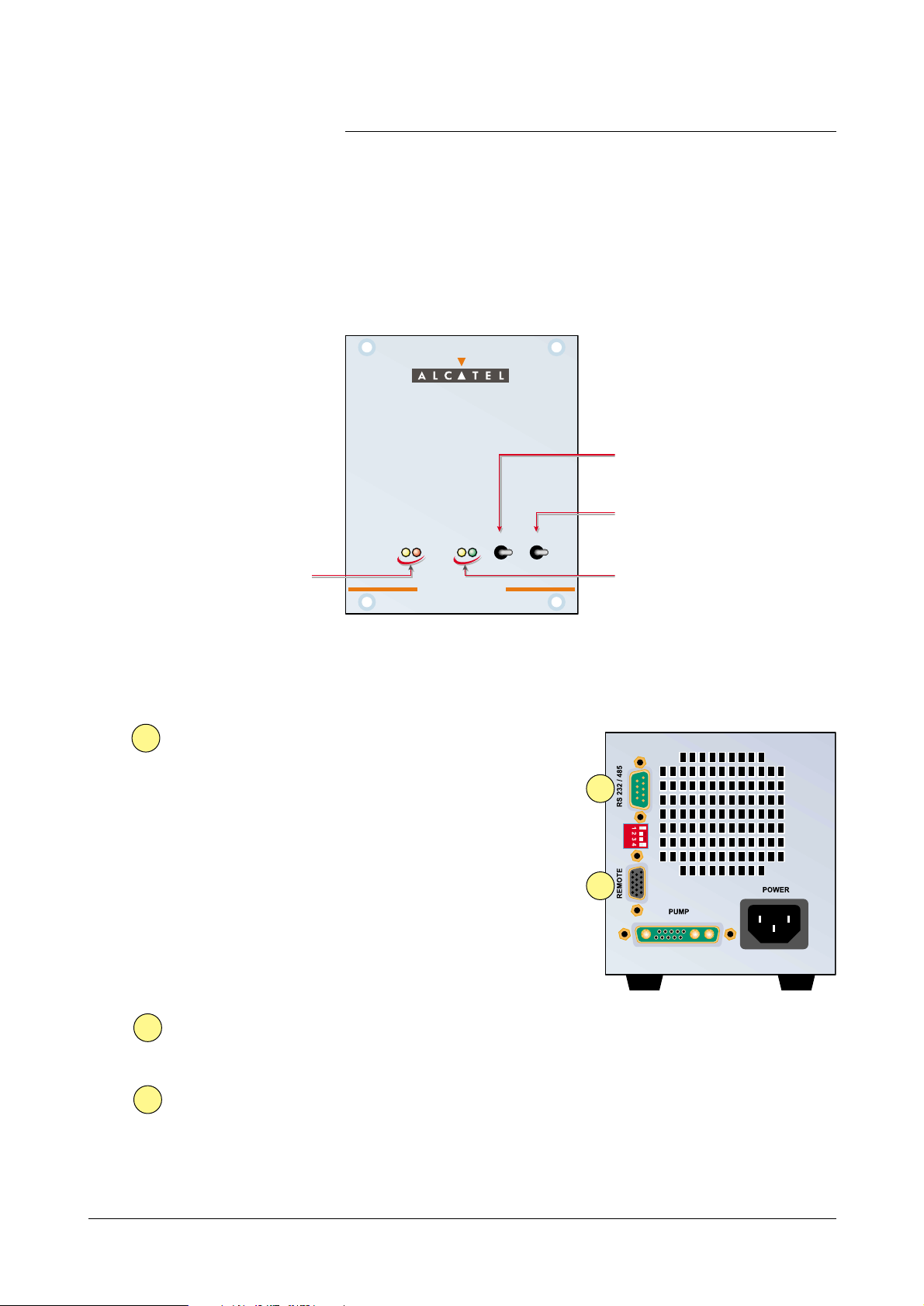
ACT 250 “box” controller control modes
Local control mode
1
2
Pump start-up switch
Pump stop switch
Pump status indicatorsController power and fault
indicators
Remote control
The remote control
Established by the
REMOTE
connector which:
- provides remote control of
the START, STOP, STANDBY,
EXTERNAL SAFETY and
MODE SELECT functions;
- replicate the available
monitoring parameters
(At speed / Starting / Fault)
on dry contacts.
The RS232 serial link is used to control and monitor the
pump using a computer.
The RS485 serial link is used to connect several pumps in
a network.
The wiring characteristics are given on page 13
RS 232 serial link
RS 485 serial link
1
2
2
There are three possible remote control modes:
There are two possible control modes:
local control and remote control.
POWER FAULT SPEED
START STOP
A C T 2 5 0A C T 2 5 0
Page 7
Presentation
Alcatel Vacuum Technology France - ACT 250 addendum
6
January 2001
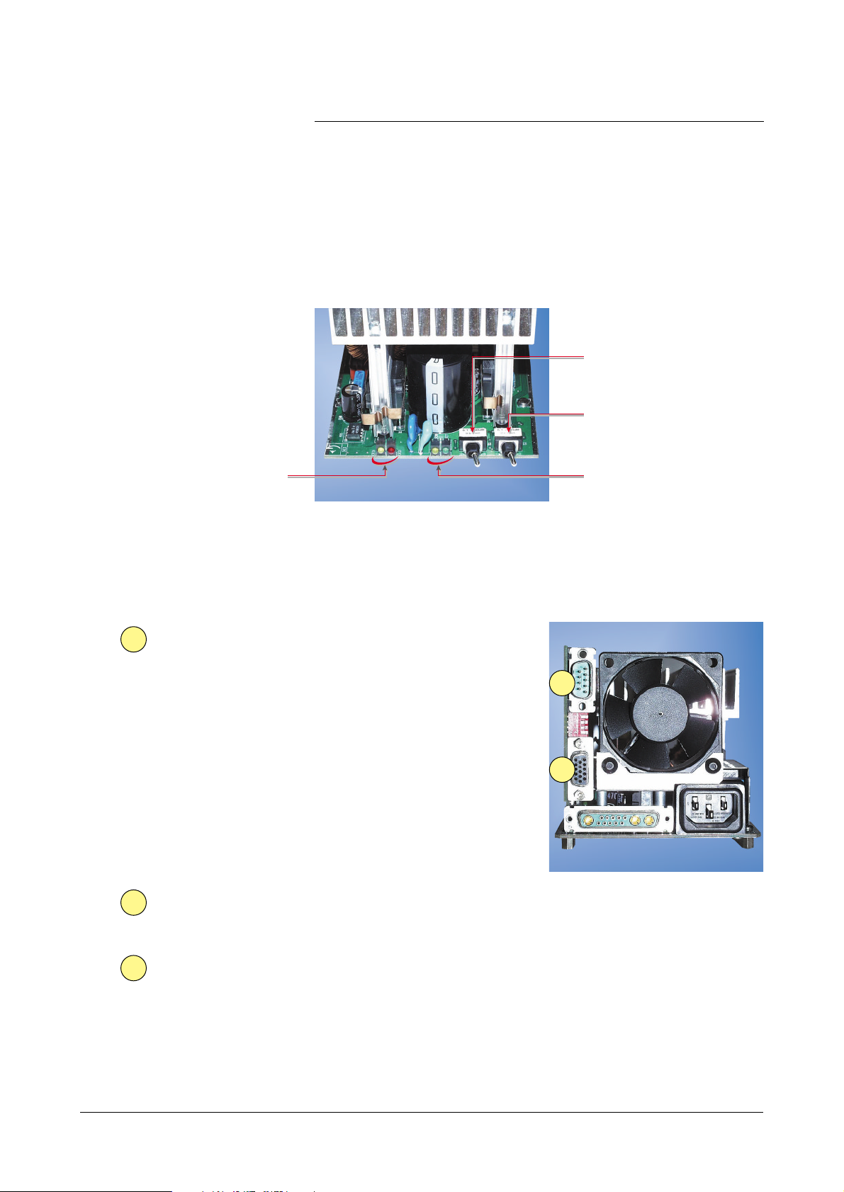
ACT 250 “OEM” controller control modes
Pump start-up switch
Pump stop switch
Pump status indicators
Controller power and fault
indicators
Local control mode
2
1
Remote control
The remote control
Established by the
REMOTE
connector which:
- provides remote control of
the START, STOP, STANDBY,
EXTERNAL SAFETY and
MODE SELECT functions;
- replicate the available
monitoring parameters
(At speed / Starting / Fault)
on dry contacts.
The RS232 serial link is used to control and monitor the
pump using a computer.
The RS485 serial link is used to connect several pumps in
a network.
The wiring characteristics are given on page 13
RS 232 serial link
RS 485 serial link
1
2
2
There are two possible control modes:
local control and remote control.
There are three possible remote control modes:
Page 8

Presentation
Alcatel Vacuum Technology France - ACT 250 addendum
7
January 2001
ACT 250 controller technical characteristics
Characteristic Unit ACT 250 “box” ACT 250 “OEM”
Weight kg 1.8 1.3
Dimensions H xWxD mm 128.4 × 106.3 × 220 95 × 100 × 212
3U × 1/4 Rack
Nominal voltage V 85 - 265
Frequency Hz 50/60
Maximum power W 300
Maximum ambient
° CT ≤ 50
temperature
Storage temperature ° C –15/+70
Customer mains
A T10A
circuit breaker rating
ACT 250 “box”
dimensions
(in mm)
0
MP
z
50
50
R
T
S
D
,
,3
,4
,
0
22
106
91
1
PU
2
0H
4
22
POWE
FAUL
ACT 2
PEE
4
28
Page 9

Presentation
Alcatel Vacuum Technology France - ACT 250 addendum
8
January 2001
ACT 250 controller
technical characteristics
5
MP
E
Y
Ø
,2
W
U
S
S
O
,1
.
,
7
a
.
ACT 250 “OEM”
dimensions
(in mm)
Attached using four M3 screws or mounted in an Alcatel
cabinet
RS232/48
REMOT
POWER SUPPL
xi
m
PU
LT
A
ER SUPPLY
O
PEED
PEED
T
TART
3
P
T
153
15
0
mini
,75
18,6
Page 10

Commissioning
Alcatel Vacuum Technology France - ACT 250 addendum
9
January 2001
Safety instructions
Before switching on the controller, the user should
study the manual and follow the safety
instructions listed in the compliance certificate
booklet supplied with the pump.
See sheet B10 in the ATP pump User Manual.
Page 11

Commissioning
Alcatel Vacuum Technology France - ACT 250 addendum
10
January 2001
ACT 250 controller electrical connections
Connect the RS232/485 serial link
cable to the connector (cable and PC
supplied by customer)
■ If the controller is remote controlled, make the various
connections on the REMOTE connector (see page 13 for
wiring details).
■ If the controller is used in local mode, the
pump can only operate if the connector plug
(ordered separately) is connected to the REMOTE
connector (see page 13 for wiring details).
Connect the controller to
the pump using the cable
(ordered separately)
Connect the
fan
(air-cooled
ATP)
Remote cable
or
Connector plug
(standard
wiring) to use
the unit in local
mode.
ATP 150
or ATP 400
pump
PC
Connect the controller to the mains
(cable ordered separately).
An earth connection must be provided.
RS configuration
Page 12
Commissioning
Alcatel Vacuum Technology France - ACT 250 addendum
11
January 2001
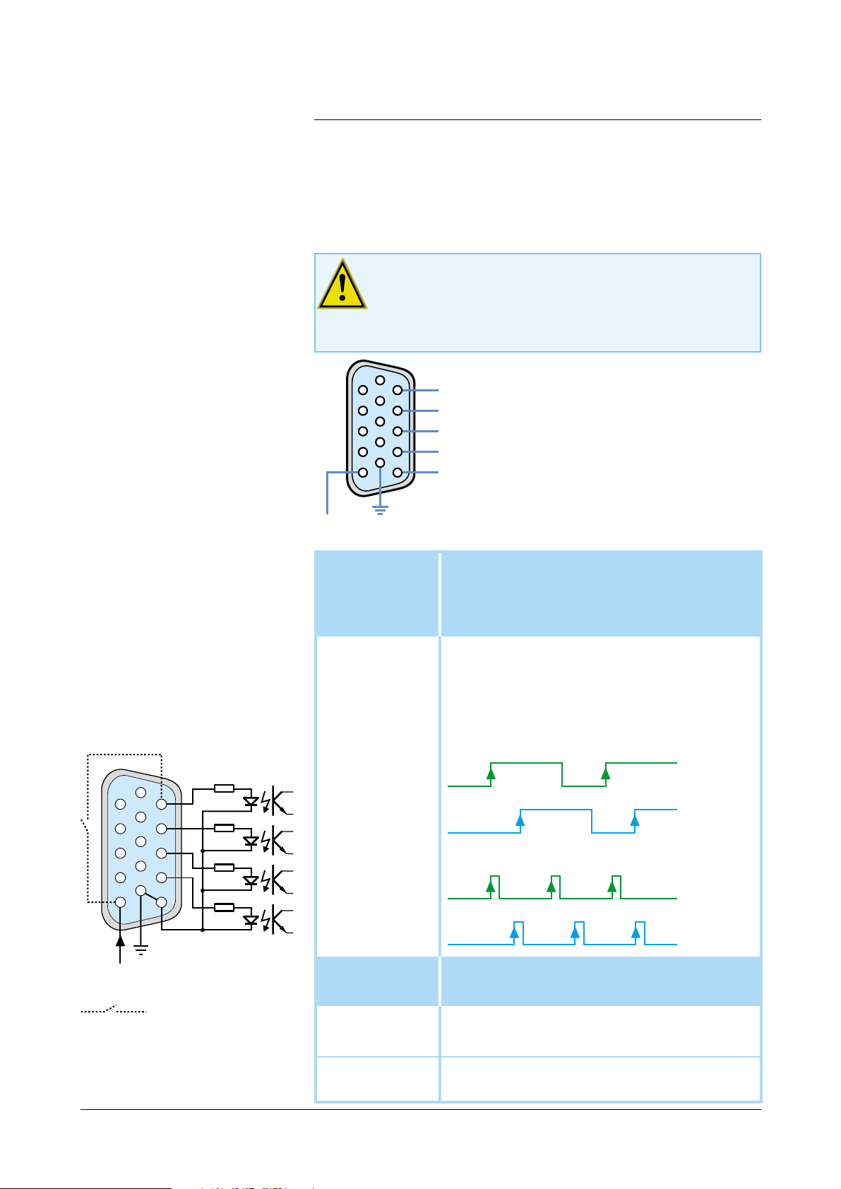
ACT 250 remote connector characteristics
When units containing the control circuits are
equipped with dry contact outputs, it is the
customer's responsibility to use the outputs in
compliance with safety regulations.
Voltage control mode
Principle of voltage-
controlled optocoupled
inputs
Cable supplied
by customer
The inputs are activated when
an AC or DC voltage is
applied. The voltage should be
between 15 and 24 Volts.
(15-pin Sub-D female
connector).
Ext. safety
11
Select Mode
12
Standby Mode
13
Start/Stop
14
15
Inactive = the external safety device is activated
(e.g. an emergency stop)
Active = pump operation authorised
Select “status” or “pulse” command mode. This
affects the START/STOP and STANDBY commands.
■ 12 -
inactive
= “
status
” mode
■ 12 -
active
= “
pulse
” mode
Inactive = operation at nominal speed
Active = operation at reduced speed
Inactive = Stop
Active = Start
Common for inputs
Example : Ext. safety activated
External contact
supplied by customer
6
11
1
12
13
14
10
15
5
6
1
10
5
+
15 V 0 V
11
12
13
14
15
+
+
+
+
–
Stop
nominal
speed
Start
Stop
standby standby
StartStop
nominal
speed
Start
StartStop
Ex. pin 14
Ex. pin 13
Ex. pin 14
O V
+15 V
nominal
speed
standby standby
nominal
speed
Ex. pin 13
Page 13

Commissioning
Alcatel Vacuum Technology France - ACT 250 addendum
12
January 2001
ACT 250 remote connector
characteristics
Signalling on output
contacts
These are dry contacts (48 V AC - 1 A) which replicate
pump status information.
When the output contact is closed:
1 - 6 The pump has reached the selected speed
2 - 7 The pump is accelerating
3 - 8 No fault signal
4 - 9 Not used
6
1
7
2
8
3
9
4
Page 14

Commissioning
Alcatel Vacuum Technology France - ACT 250 addendum
13
January 2001
ACT 250 remote connector wiring
Use in local mode
■ Standard connector plug (factory wired)
Use in remote control
mode
■ Without galvanic isolation (not recommended)
Wiring seen from solder side.
■ With galvanic isolation (recommended)
Wiring seen from solder side.
compulsory screen
customer
device
ACT unit
ground
device ground
compulsory screen
customer
device
15 V –> 24 V
ACT unit
ground
device ground
Wiring seen from solder side
➞ Ext. safety
➞ Select. Mode
➞ Standby Mode
➞ Start/Stop
➞ Common for
inputs
➞ Ext. safety
➞ Select. Mode
➞ Standby Mode
➞ Start/Stop
The voltage used to power the contacts is supplied by the
ACT 250 (terminal 5). The disadvantage of this method is
the risk of exposing this voltage to external interference
(see also diagrams on page 11 ).
6
11
1
12
10
15
5
6
11
1
12
13
14
10
15
5
1
5
6
11
12
13
14
10
15
Page 15

Commissioning
Alcatel Vacuum Technology France - ACT 250 addendum
14
January 2001
RS 232 / 485 serial link
Wiring the RS 232 or
RS 485 serial link
See sheet B 110 in the ATP Series Pump User Manual.
Configuring the RS 232
or RS 485 serial link
The link is configured using switches on the rear panel of
the controller.
Switch description 0 1
1 parity type odd even
2 parity no yes
3 baud rate 9600 4800
4 RS type RS 485 RS 232
Factory configuration: 9600 baud, NO parity, RS 232
Use
See the detailed list of commands on page 15
01
Page 16

Commissioning
Alcatel Vacuum Technology France - ACT 250 addendum
15
January 2001
Detailed description of RS commands
Syntax conventions
applicable to all
commands
Status values
Error messages
ADR
Syntax
Result
adr = address, from 000 to 255
<CR> Carriage Return (ascii 13)
<LF> Line Feed (ascii 10); shown in brackets as it is not
compulsory.
ok : command executed correctly
Err0 : adjustment error (out of bounds)
Err1 : command error (syntax)
Err2 : parameter error (e.g. non-hexadecimal character)
Err3 : context error
Err4 : checksum error
Specifies the address of the device for networking
#adrADRaaa<CR>[<LF>]
adr = address of device before this command
aaa = new address of device
condition : 000 ≤ aaa ≤ 255
#aaa,ok or Err2
This command is used to allocate a specific number to each device
on the network
(loop for RS232 or parallel for RS485).
Note: it is important to note the number allocated to
each device.
Page 17

Commissioning
Alcatel Vacuum Technology France - ACT 250 addendum
16
January 2001
Detailed description of RS commands
CKS
Syntax
Result
CYC
Syntax
Result
Enables or disables checksums on reply strings
#adrCKSON<CR>[<LF>]
Enables the ASCII checksum character at the end of a
reply string
or
#adrCKSOFF<CR>[<LF>]
Disables the ASCII checksum character at the end of a
reply string
#adr,ok,S for CKSON
#adr,ok for CKSOFF
This feature enables the user to test whether a transmission error has
occurred for the reply string.
S is a character whose ASCII value is the 7-bit checksum of all ASCII
character values from the start of the reply string to the character
preceding the S. The 8th bit of S (most significant bit) is always 1.
Starts the specified running-in cycle
#adrCYC1<CR>[<LF>] to start running-in program 1,
or
#adrCYC2<CR>[<LF>] to start running-in program 2
#adr,ok
Running-in program 1 should be executed after a pump maintenance
operation (change of bearings).
At the end of the program, the pump maintenance parameters are
updated and the “maintenance requested” alert can be cleared.
Program 2 is used after regreasing (ATP series only), or after
prolonged storage (ATH 20/40 only).
Page 18

Commissioning
Alcatel Vacuum Technology France - ACT 250 addendum
17
January 2001
Detailed description of RS commands
DLI
Syntax
Result
See also: DLR
DLR
Syntax
Result
See also: DLI, LNG, SEP, SHT
Enables DataLogger operation (RS232 only)
#adrDLR<CR>[<LF>]
#adr,sssss,nnnnn,iiii,ttttt,uuuu.o,www,ppp,vvv
Returns current values :
sssss : current speed (rpm)
nnnnn : speed set point (rpm)
iiii : current value (mA)
ttttt :
pump operating time (hours)
uuuu.o:
(reserved)
www : pwm
(reserved)
ppp : pump temperature (°C)
vvv : variator temperature (°C)
The main characteristics of the pump and its controller are sent over
the RS link, at the rate defined by the DLI command.
Note: any new characters arriving on the serial port (RS 232) will
cancel the automatic DataLogger transmission.
Defines the DataLogger transmission interval
#adrDLIxxx<CR>[<LF>]
xxx: DataLogger transmission interval in seconds
condition: 001 ≤ xxx ≤ 255
#adr,ok or Err2
Note: if ok, the interval sent is stored in user memory.
Page 19

Commissioning
Alcatel Vacuum Technology France - ACT 250 addendum
18
January 2001
Detailed description of RS commands
HDR
Syntax
Result
IDN
Syntax
Result
Identifies the device which is communicating, and its
software version
#adrIDN<CR>[<LF>]
#adr, VS.... - Vx.zz’
or
#adr, VS.... - Vx.zz for “Alcatel pump type”
Returns the type of Variator Supervisor, the software version (x), the
software edition (zz), and the type of pump for which this variator is
set up.
Defines the start character for a command reply string
#adrHDRnnn<CR>[<LF>]
nnn: 3-digit decimal value of the ascii code of the
corresponding character (with leading zeros).
condition : 020 •nnn •255
?adr,ok ? is the desired character.
#adr,ErrX if error
Allows the user to distinguish between the first character in a “command” string
(for which # cannot be changed) and the first character of a “reply” string.
Affects the first character of all replies.
Default value: the hash sign, # (ascii code = 035)
If ok, the selected value is automatically stored in user memory.
ECH
Syntax
Result
Enables or disables command echoing
#adrECHON<CR>[<LF>]
enables all characters received to be echoed over the serial port
or
#adrECHOFF<CR>[<LF>]
disables characters received from being echoed over the serial port.
#adr,ok
Comments:
- This command is disabled in RS 485 operation, the value OFF
is required.
- Using a loop-type RS 232 network requires “ECHON”.
Page 20

Commissioning
Alcatel Vacuum Technology France - ACT 250 addendum
19
January 2001
Detailed description of RS commands
LEV
Syntax
Result
LNG
Syntax
Result
See also: SHT
Returns the state of the parameters defined by SET
#adrLEV<CR>[<LF>]
#adr,nnnnn,sssss,aaaa,hhhhh or
#adr,nnnnn rpm,sssss rpm,aaaa mA,hhhhh hours
Returns the current values:
nnnnn : speed set point
sssss : stand-by speed
aaaa : max. current set point
hhhhh : alert level for pump bearing maintenance
Returns the strings sent with the identification sub-strings
#adrLNG<CR>[<LF>]
#adr,ok
AVT>
Allows the parameters returned by the DLR, LEV and SPD commands
to be identified with sub-strings. DLR, LEV, SPD.
Also generates the “AVT>” prompt each time a <CR> character is
received.
NSP
Syntax
Result
See also: RPM, SBY
Switches the speed set point to the nominal speed value
#adrNSP<CR>[<LF>]
#adr,ok
The speed set point for the pump is set to its nominal value.
This configuration is automatically saved in user memory.
This mode of operation prevents the use of the “RPM” command.
Page 21

Commissioning
Alcatel Vacuum Technology France - ACT 250 addendum
20
January 2001
Detailed description of RS commands
OPT
Syntax
Result
See also: SEL
Used to select possible user choices
#adrOPT2 n<CR>[<LF>]
choice of temperature unit:
n = 0 : degrees Centigrade
n = 1 : degrees Fahrenheit
#adr,ok
Comment: The choice of the temperature unit affects
the results of the DLR and STA strings.
RPM
Syntax
Result
See also: NSP, SBY
Defines the speed set point in stand-by mode
#adrRPM nnnnn<CR>[<LF>] or #adrRPMnnnnn<CR>[<LF>]
#adr,ok or #adr,ErrX
X = 1, out of range; 2, parameters ; 3, context (not in Stand-by mode)
Comment: if ok, the new speed is automatically stored in user
memory.
Saves the internal parameters in user memory
#adrSAV<CR>[<LF>]
#adr,ok
Saves the current context (except for running-in cycles). If this
command is sent when the pump is powered up, it can for example
allow automatic re-start in the event of a power cut.
SAV
Syntax
Result
Page 22

Commissioning
Alcatel Vacuum Technology France - ACT 250 addendum
21
January 2001
Detailed description of RS commands
SBY
Syntax
Result
See also: NSP, RPM
Switches the speed set point to the stand-by value
#adrSBY<CR>[<LF>]
#adr,ok
Resets the stand-by speed to its last stored value, and allows it to be
modified if an “RPM” command is sent.
This configuration is automatically stored in user memory.
SEL
Syntax
Result
Returns the state of the parameters defined by OPT
#adrSEL<CR>[<LF>]
#adr,a,u
a: Reserved
u: Returns the choice of temperature unit::
u = 0: degrees Centigrade u = 1: degrees Fahrenheit
Defines the character which separates the parameters
in a reply
#adrSEPnnn<CR>[<LF>]
3-digit decimal value of the ASCII code of the desired character (with leading zeros if necessary).
condition: 000 ≤ nnn ≤ 255
#adr,ok or #adr,ErrX if error
Allows the user to select the character which separates
the parameters returned by the DLR, STA and LEV
commands. Default value: comma “,” ASCII code = 044
If ok, the selected value is automatically stored in user memory.
SEP
Syntax
Result
Page 23

Commissioning
Alcatel Vacuum Technology France - ACT 250 addendum
22
January 2001
Detailed description of RS commands
SET
Syntax
Result
See also: LEV
SHT
Syntax
Result
See also: LNG
SPD
Syntax
Result
See also: LNG, SHT
Defines the internal operating parameters
#adrSET1 hhhhh<CR>[<LF>] : maintenance time limit
000<hhhhh<65535
#adr,ok or #adr,ErrX
Return the DataLogger string without the identification
sub-string
#adrSHT<CR>[<LF>]
#adr,ok
The strings sent following DLR, LEV and SPD commands are sent
without parameter identification sub-strings (e.g. without units).
Returns the current speed
#adrSPD<CR>[<LF>]
#adr,nnnnn
#adr,nnnnn rpm
Page 24

Commissioning
Alcatel Vacuum Technology France - ACT 250 addendum
23
January 2001
Detailed description of RS commands
STA
Syntax
Result
TMP
Syntax
Result
Returns the status of the internal dynamic parameters
#adrSTA<CR>[<LF>]
#adr,xxxxxx,yyyyyy,zzzzzz,sssss,iiii,www,ppp,vvv,ttttt<CR><LF>
adr: address
543210
xxxxxx status bits: yyyyyy fault bits:
5 - RS echo (1->off) 5 - variator temperature
4 - String long (0) / short (1) 4 - motor temperature
3 - On (1) / Off (0) 3 - excess current
2 - reduced or nominal 2 - sensors or start-up
speed reached(1) 1 - external
1 - standby (1) 0 - pump not connected
0 - running-in (1)
zzzzzz alert bits: sssss current speed value in rpm
5 - reserved (future use) iiii current value in mA
4 - reserved (future use) www reserved (pwm value)
3 - variator temperature ppp pump temperature value
2 - motor temperature vvv variator temperature
1 - start-up time exceeded (future) ttttt pump operating time value
0 - operating time exceeded
Reminder: The “#” character at the start of the reply
string can be set with the “HDR” command.
The “,” character which separates the parameters in
the reply string can be modified with the “SEP”
command.
Defines the turbomolecular pump operating state
#adrTMPON<CR>[<LF>] : start pump rotation
#adrTMPOFF<CR>[<LF>]: stop pump
#adr,ok or #adr,Err3 if the pump is already in the state
requested (context error)
Page 25

Use
Alcatel Vacuum Technology France - ACT 250 addendum
24
January 2001
Controlling the pump from the ACT 250 controller
Once all connections are complete, plug the controller into
the mains.
A C T 2 5 0A C T 2 5 0
POWER FAULT SPEED
START STOP
Indicator lights
“box” version
“OEM” version
Yellow lit
Controller on
Red lit
Controller fault
Red flashing
Controller alert
Yellow lit
pump rotation
speed
accelerating
Green flashing
The pump rotation speed is
greater than the selected
speed (speed reduction during
operation)
Green lit
The pump has attained the
selected speed.
Page 26

Use
Alcatel Vacuum Technology France - ACT 250 addendum
25
January 2001
Controlling the pump from the ACT 250
controller
START
STOP
Starting the pump with
the START switch
Stopping the pump with
the STOP switch
The pump is started up to reach the selected speed. The
yellow rising speed indicator light comes on. When the
pump reaches its selected speed, the yellow indicator light
goes off and the green indicator light comes on.
The rotation speed monitoring indicator lights go off.
The pump motor is no longer powered, the pump
decelerates.
Page 27
Use
Alcatel Vacuum Technology France - ACT 250 addendum
26
January 2001
Controller functions
Precautions
Local mode operation
The Start and Stop functions use switches located on the
front panel of the “box” version and on the board for the
“OEM” version.
The “OEM” version of the ACT 250 has been
designed with electrical safety and
electromagnetic compatibility standards in mind.
It is the user’s responsibility to provide external shielding
to comply with EMC and electrical safety standards.
POWER FAULT SPEED
START STOP
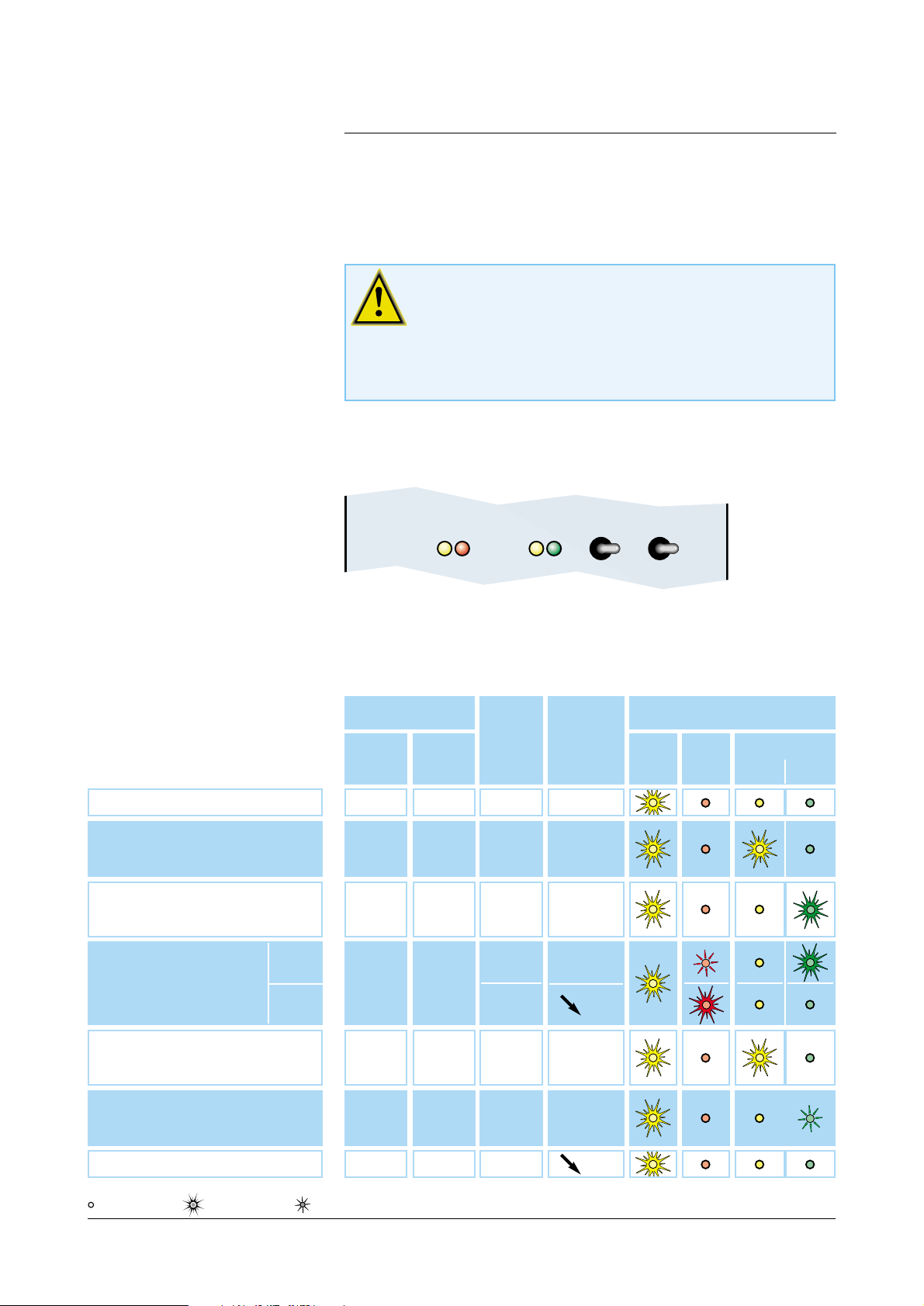
The pump’s operating status is shown by the state of the
“POWER” indicator (yellow) and the three “FAULT” (red)
and “SPEED” (yellow and green) indicators.
Indication of rotation
during operation
(controller on)
Pump
motor on
Pump
rotation
speed
State of indicators
Power
Yellow
Fault
Red
Speed
Yellow Green
Press button
START STOP
1 Before start-up
2 During start-up
3 Pump at nominal speed
5 Overload
7 Pumping stopped
0
1
0
0
0
0
0
0
0
1
NO
YES
YES
YES
NO
0
< selected
speed
= selected
speed
< selected
speed
0
6 Speed set point lowered
0 0 YES
> selected
speed
indicator off indicator on indicator flashing
4 Alert
Fault
Alert or fault
triggered
(see page 27 )
0 0
YES
NO
≤ selected
speed
0
Page 28

Use
Alcatel Vacuum Technology France - ACT 250 addendum
27
January 2001
Controller functions
Fault monitoring
■ Alerts are indicated by:
- flashing red indicator. The pump power supply is
maintained.
■ Faults are indicated by:
- lit red indicator. The pump is stopped as soon as a fault
is detected.
Alerts and faults shown by the indicator light include:
- controller overheating,
- pump motor overheating,
- cable disconnected (pump / controller)
- external safety device open,
- overcurrent on speed variator.
Alerts and faults can be identified using the serial link (see
page 23, STA command).
Page 29

France
Alcatel Vacuum Technology - France
98, avenue de Brogny - BP 2069
74009 ANNECY - Cedex
Tel : (33) 4 50 65 77 77
Fax : (33) 4 50 65 77 89
Germany
Alcatel Hochvakuum Technik GmbH
Am Kreuzeck 10
D – 97877 WERTHEIM
Tel: (49) 9342 96100
Fax: (49) 9342 961030
Italy
Alcatel Vacuum Systems S.p.A
Via Trento, 30
20059 VIMERCATE (MI)
Tel : (39) 039 686 3855
Fax : (39) 039 667 125
Japan
Alcatel Japan LTD
13 fl. Dai Tokyo - Kasai Shinjuku bldg
3 - 25 - 3 - Yoyogi, Shibuya - ku
TOKYO 1510053 - JAPAN
Tel : (81) 3 5302 4350
Fax : (81) 3 5302 4332
Korea
Alcatel Vacuum Technology Korea
5thFloor, Sunghyun B/D
10-5, Karak-Dong, Songpa-Ku
Seoul - SOUTH KOREA
Tel : (82) 2 409 6277
Fax : (82) 2 409 6279
United Kingdom
Alcatel Vacuum Technology UK Ltd
8 Bain Square
Kirkton Campus
Livingstone - WEST LOTHIAN
EH - 547 DQ - SCOTLAND
United Kingdom
Tel. (44) 1 506 418 000
Fax. (44) 1 506 418 002
USA
Alcatel Vacuum Products
67 Sharp Street
HINGHAM, MA. 02043
USA
Tel :1(781) 331 4200
Fax :1(781) 331 4230
Alcatel Vacuum Technology - France - 98, avenue de Brogny - BP 2069 - 74009 ANNECY Cedex France
Tel. (33) 4 50 65 77 77 - Fax (33) 4 50 65 77 89 - Telex 385 153 F
Web site: www.alcatel.com
Publication: Alcatel - Realization: AXESS (33) 4 75 42 35 90 - Edition 01 - January 2001
 Loading...