

Akai DVR-4015-VSS Service Manual

DVD PLAYER
Model:
DVR4015VSS
SERVICE MANUAL
www.akai.ru

目录
▲ Safety information ----------------------------3
General guid-----------------------------3
1.
Low zeta potential leaking inspection ---3
2.
High zeta potential leaking inspection --3
3.
▲ Device avoiding ES(Electric Susceptible)
Influence of ESD (Electric Susceptible
Discharge)-----------------------------------------3
Technical specification ----------------------4
▲
Mechanical diagram ------------------ ------8
▲
Mechanical Parts------------------------- 9
Packing and accessories ---------------------10
▲
Disassemble and assemble-------------------11
▲
Take out disc from trouble player ----11
1.
PCB position ------------------------11
2.
Disassemble and assemble parts of the unit
▲
▲ Attachment 3---------------------------32
Component list
▲
AV output board component list --------33
1.
Decoder board component list ----------36
2.
Control board component list -----------39
3.
-----------------------------------------------12
Can open the tray by electricity -----12
1.
Can not open the tray by electricity --12
2.
Assemble the unit -------------------12
3.
▲ Attachment 1----------------- 13
▲ Block Diagram/Electric circuit diagram
Block diagram ------------------------14
1.
Electric circuit diagram ---------------15
2.
Decoder board diagram ---------------16
3.
AV output board diagram -------------20
4.
Control board diagram ----------------23
5.
▲ Attachment 2------------------24
▲ PCB Diagram
1. Upper decode board PCB diagram ----25
Lower decoder board PCB diagram ---26
2.
AV output board PCB diagram --------27
3.
4. Control board PCB diagram -----30

SAFETY INFORMATION
General guide
1.Observe the original circuit during maintenance. if short
circuit occurs, change the over-hot or damaged components.
2.Observe all the protective device after maintenance, such
as whether the shielding cover or paper is assembled well.
3.To avoid electric shock, please inspect electricity leakage
after maintenance
1.Take out AC cord and connect a piece of wire between two
legs of the outlet.
2.Use Gear R x 10K of the voltmeter to measure the spares
Device avoiding ES(Electric Susceptible)
Influence of ESD (Electric Susceptible Discharge
exceeded the restrained figure, electric shock should be
possibly suffered. Do maintain the unit and inspect once
more before return to the user.
Device avoiding ES influence of ESD.
Some solid semi-conductor devices are easy to be
damaged by static electricity. These devices are generally
called ES device. The typical devices are IC, field effect
Low zeta potential leaking inspection
component and semi-conductor laser diode.
The following technology helps to abate the danger of
ESD on body before handle any semi-conductor or
semi-conductor component. Or wear the ESD bangle availed
on AC outlet and exposed metallic part with short circuit.
The resistance between screw cap, control shaft should be
unlimited.
from the market to eliminate the threaten of static electricity
on human body.
2.Put the electronic parts with ES device on the surface of
creepage checking circuit
to have discover metal
accessory of equipment
AC voltage table
uF
Ω
cold water
canal(earthing)
picture 1
High zeta potential leakage inspection
.As illustrated 1, Connect Resistor with 1.5K, 10W and
capacitor 0.15 between exposed metallic part and device of
fine connection to the earth (water pipe etc.).
2.Plug-in AC cord directly to AC outlet. Do not inspect with
shield adaptor.
3.Utilize 1000 or more sensitive voltmeter to measure
alternating voltage.
4.Turn back the AC plug-in from AC outlet then iterate the
inspection as above.
5.Inspect the voltage of the resistor between other exposed
metallic parts and the earth with the same way.
6. The voltage must not be over than 0.75Vrms at any points
on the resistor. Electric leakage should not be over 0.5mA
when processing high voltage leakage testing through
conductor such as aluminium foil after take them out in order
to protect static electricity from accumulation and explosion.
3.Solder or disassemble ES device through iron connecting
the earth.
4. Utilize device only anti-static electricity to disassemble
soldering tin. Non-anti static electricity device (ESC
protection) will release ES that damage ES device.
5.Do not use chemical volatile releasing static electricity
that leads to damage ES device
6. Unless preparation for pre-assembling has been made, do
not take out the ES device to be changed from the protective
packing ( most of the changed ES devices are packed
together with anti-static electrical foam or similar electric
material, besides, countermeasures for down-lead short
circuit are taken.).
7. Protective material should connect the model or the circuit
component to be assembled in it before taking out the
protective material from the ES device.
Note: do not bear electricity to the model or the circuit, and
pay attention to all the other safety information.
8. When disassembling and replacing the ES device, try to
reduce body movement (Or, the movement of legs, the
friction of fibrous of clothes, or elevating the legs from the
floor will generate static electricity ESD, causing damage to
the ES device.).

Technical specification
DVD Electric gudideline 1:Video parts
NO. Test items Test point Performance request Units Remake
1 video 1.0±0.2 Vp-p
Y 0.7±0.14 Vp-p
2
3 Y.Cr. Cb/Y.Pr.Pb 0.7+/-0.14 Vp-p
4
5 Level definition ≥450 lines
6 bandwidth(+3/-6 dB) ≥5.5 MHz 100KHz 0 dB
7 differential coefficient bit DP ≤2 degree 75Ω loads
8 Lum non distortion ≤5 % 75Ω loads
9 Differential plus DG ≤2 % 75Ω loads
10 Y ≥56 (except power) dB 75Ω loads
11 C
12
2:Audio(Test signals:TCD-784)
NO. Test items Test point Performance request Units Remark
1
2 Breadth rage response ± 1.5 dB DVD(LPCM) 20Hz~20KHz
3 S/N ≥80 dB A count power
4 THD 10 % 1KHz A count power 10W
5 Condition areas 90 dB 1KHz A count power
6 Separate degree 70 dB 1KHz A count power
7 Channel inbalance ≤1.0 dB DVD(LPCM)、CD
8 Coaxial output range 0.5±20% Vp-p 75Ω± 1% loads
9 Optical output wavelengh (λp) 660±30 nm
3:Other characteristic parts
NO. Test items Test point Capability request Units Remark
1 Load time 10 S
2 Remote control for instance ≥5 m Front surface±15°areas
3 Input power voltage 230V±10% 50Hz
4 Expend power 110W Normal works
5 Deposited condition of temperature -25~+55 °C
6 Works condition of temperature 0~+40 °C
7 Freedom lower Accord GB/T 2423.8-1995 request
8 Disc formats
4:Test condition1.condition:normal temperature,normal voltage 2.power voltage:AC 230V 50Hz
3. speaker impedance: 8Ω
Output
range
S/N ratio
Lines audio input, output levels
S-vid
eo
C
R.G.B 0.7+/-0.14 Vp-p
R
G
B
chroma 0.88±0.176 Vp-p
Color sync 0.3±0.06 Vp-p
U channel ≥50 dB 75Ω loads
V channel ≥50 dB 75Ω loads
R channel ≥50 dB 75Ω loads
G channel ≥50 dB 75Ω loads
B channel ≥50 dB 75Ω loads
(1)DVD:
12cm single side, single layer;12cm single face, double layer;12cm double face. Double layer;
8cm single face, single layer; 8cm single face, double layer;8cm double face, double layer.
(2)CD disc:12cm disc,8cm disc
1.8+0.2/-0.8 Vrms
4
DVD(LPCM)、CD
Audio input impedance:10KΩ
Technical specification
AV output board electric guideline production model:AKAI DV-R4015VSS
Items Unit Model
Value
POWER PARTS
1 Input voltage areas V
2 Rating output voltage
and current
-16V 2.2A +16V 3A
-16V 2.2A +16V 3A
AC
+5V 1.3A +5V 1.5A
AC3.7V
-24V 50mA -24V 50mA
3 The least of output
power
4 +5 output veins wave mV <50
4 Power tune rate(+5V
port)
6 Loads tune rate(+5V
port)
AV output parts
7 Works voltage V ±16 ±20 RL=8Ω
8 Static state current mA 380 630
9 Output power W 12 14
10 (FR/FL/SR/SL/CENT) 9 11
11 Subwoofer output
power
12 After all humorous
wave distortion
0.7
13 Bunch sound dB 70
60 50
14 S/N dB
15 Breadth response dB
W 110 Input voltage AC230 ±
% 5 Input voltage AC230 ±
% 5 current10mA-1.5A
W 30 35
% 0.03 0.07
230±10%
100mA
80
± 1.5
Limited
value
AC3.7V
120mA
75
40~18KHz
Test condition
10%V
10%V
THD = 10% RL = 8Ω
THD = 1% RL = 8Ω
THD = 10% RL = 8Ω
RL = 8Ω ; PO = 1W; f = 1KHz
RL = 8Ω ;PO = 0.1 to 7W;f = 100Hz to
15KHz
f = 1KHz
f = 10KHz
A count power
5

Electric Specification book
FM electric guideline Model:AKAI DV-R4015VSS
Test condition:
1.power supply voltage: AC 230V 50Hz 2.standard output power: 1W
3.sound speaker impedance: 8Ω
4.standard confection: 1000Hz 22.5 KHz frequency deflection 5.Aerials impedance:75Ω
NO.
1 Intermediate frequency MHz 10.7 +/-0.1
2 Cover with areas MHz 87.5- 108 +/-0.1
3 Graduation
error
4 Chirp
limited is
sensitive to
degree
5
S/N ratio (98MHz,input 1mV except power)
6 -3dB Limited delicacy degree
7
Intermediate frequency restrain(90MHz) dB 50 45
8
Lens restrain compete(106MHz) dB 28 22
9
Distortion degree(1mV input) % 0.6 1.5
10
Confection AC sound(input 5mV) dB 50 40
11 AFC areas(1mV input,-3dB)
12
AM restrain(1mv input, confection degree 30%) dB 32 26
13
Output power ( distortion10%,60Khzfrequency
leaning, 1mv input)
14
Breadth response(-3dB) Hz
15
The lease of volume mV 1 3
16 Locking station delicacy degree
17 separate degree
Test items units Standard Limited Error
90MHz
106MHz
90MHz 22.5KHz frequency
deflection S/N 30dB
98MHz 22.5KHz frequency
deflection S/N 30dB
106MHz 22.5KHz frequency
deflection S/N 30dB
KHz
KHz
dBµV ≤26 ≤32
dBµV ≤26 ≤32
dBµV ≤26 ≤32
dB
µV 10 20
KHz
W 10
dB ≥28
dB 25 20
≥50 ≥34
40Hz-12.5KHz
100Hz-8KHz
6

Electric Specification book
Mw electric guideline Model:AKAI DV-R4015VSS
Test condition:
1.power supply voltage: AC 230V 50Hz 2.standard output power:1W
3.loundspeaker impedance: 8Ω 4.standard confection: 400Hz 30% confection degree
No
.
1 Intermediate frequency KHz 450 +/-3
2 Cover with areas KHz 522-1620 +/-5
Chirp limited is
4
sensitive to degree
S/N SNR(999 KHz ,input 10mV/M, standard confection 1KHz A count power)
5
6
Intermediate frequency restrain compete(612KHz) dB 45 35
7
Lens restrain compete(1413KHz) dB ≥34 ≥20
8
AFC(input100mV/M) dB 30 20
Distortion
9
10 -6dBbandwidth (20dB S/N) KHz
11
12
13
14
15
16
17 Locking station delicacy degree
degree
whistle(input 5mV/M,IFx1 IFx2) % 3 10
Output
power
+/-10KHz selectivity (on 1000KHz 20dB S/N) dB 14 8
Breadths response (-6 dB, input 5mV/M) Hz 40Hz-4KHz 100Hz-3.1
Confection AC sound(input 100mV/M) dB 40 35
The least of volume yawp mV 1 3
S/N 20dB, 612KHz
S/N 20dB, 999KHz
S/N 20dB,1413KHz
5mV/M input,30%confection degree % 1 3
100mV/M input,80%confection degree % 3 5
Volume largest W
Distortion degree10% ,80% confection, input5mV/M
Test Items Unit Standard Limited Error
dBµV/M
dBµV/M ≤70 ≤75
dBµV/M ≤70 ≤75
dB ≥40 ≥34
W 10
dB ≤90
8 5-10
≤75
5KHz
7
36 36
36
36
11
37
34
1
4
5
37
34
34
34
34
15
13
14
34
9
17
12
34
10
37
2
3
37
37
37
36
35
16
34
7
6
38
19
35
17
34
8
36
18
35
20
36
32
36
30
35
35
26
35
18
38
25
35
35
25
35
23
31
33
34
34
33
34
34
33
34
29
35
24
35
25
27
25
35
35
25
25
35
25
38
28
35
25
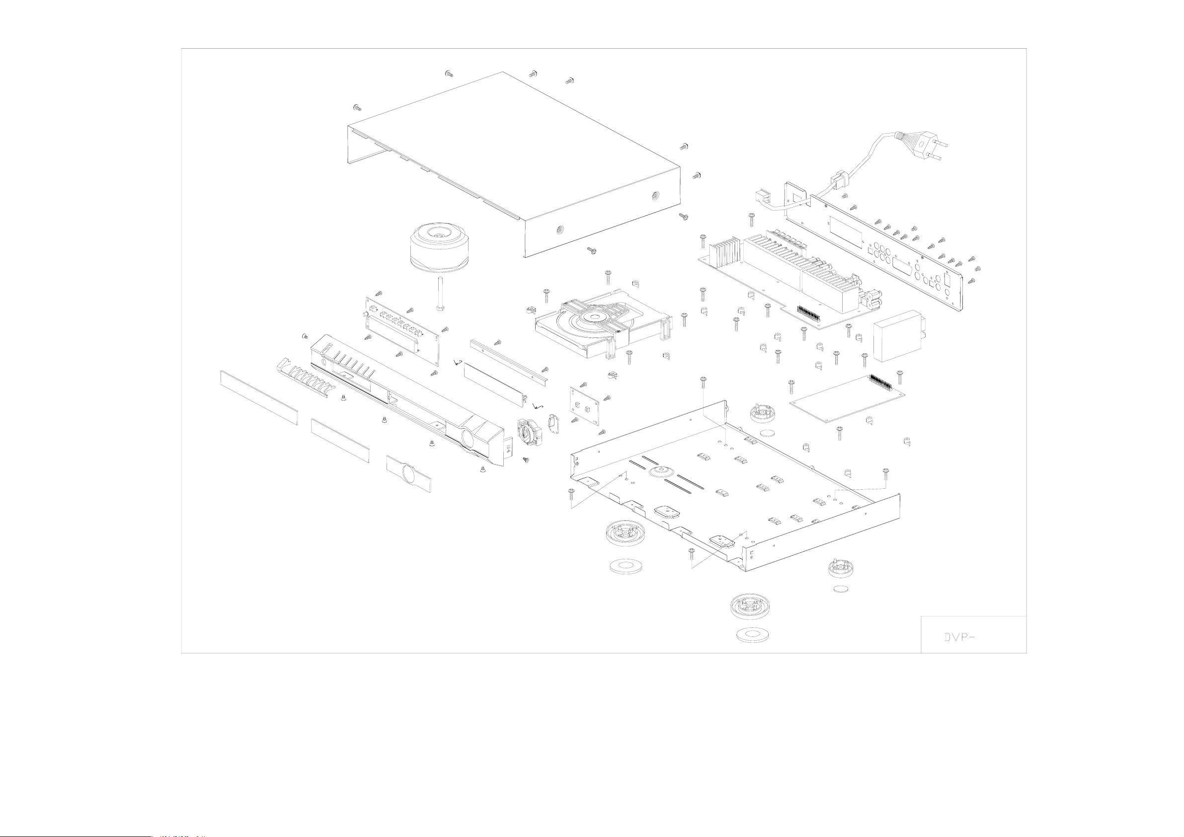
Mechanic parts of decompose diagram
8
21
38
22
23
21
22
23
24

MACHINE PARTS OF COMPONENT LIST
NO.
2
3
4
5
6
7
8
9
10
11
12
13
14
15
16
17
18
19
20
21
22
23
24
25
26
27
28
29
30
31
32
33
34
35
36
37
38
MATERIAL NO.
Y9-01012C-33
Y9-01012C-32
Y9-01012C-31
Y1-010171-00
Q1-010120-14
Y1-0101G1-00
Y9-01016C-20
A5-010120-40
Q1-0101D0-04
Y3-060160-10
A5-010120-41
A6-000000-41
T1-400022-00
N2-604829-79
N4-230101-L0
N4-230101-R0
Y3-01016C-24
Y3-140160-20
Q3-050121-00
Q4-010120-00
Y3-130150-20
Y3-130150-50
Y3-130151-20
Y3-130151-50
Y3-030260-20
A5-010120-20
A5-010120-10
A8-114100-20
Q2-010120-16
S1-811048-01
Y6-440003-00
WD-222232-01
N2-300615-54
N2-300812-19
N2-301215-54
N2-300815-54
N2-300614-54
N2-300812-14
APPELLATION
Lens1
Lens3
Lens2
7KEY key
surface
Vol button
Lead
control board
disc tray
uuper cover board plank
control board
core
round power transformer
transformer sleeping bolt K60×48
door spring
door spring(right)
core plank
PCB plank(core using
uuper cover board
motherboard
front f e et
front f e et mat
back feet
back feet mat
PCB mat
AV output board
decode board
Incept nog
back baord
power switchs PS8-11-D-048
line button SB4F-4
power cord2.2m 250V 2.5A VDE attention
PWTT3×6(adding forcedly)white
PA3×8
PWTT3
PWB3
KTT3
ST3×8 PANi
(left)
)
×12(adding forcedly)white
×8(adding forcedly)white
×6 sink head
QTY
1
1
1
1
1
1
1
1
1
1
2
2
2
2
2
2
13
1
1
1
1
1
1
1
3
25
17
8
6
4
REMARK
PVC
PVC
PVC
ABS
ABS
ABS
ACRYL
ABS
cool ro ll bao r d
SONY optics head,RongXinDa plank
carbon wires
carbon wires
ABS
ABS
1mm electrolyte board
ABS
sponge
ABS
sponge
ABS
KST-MV114MA1-B0
electrolyte board
HuaJie company
power cord and back board
LianDong company(pin) HengZhiQian(lines)
motherboard/back surface
control board,back port
decode board、output board、core/motherboard
uuper cover/motherboard
surface
、m otherboard
feet/motherboard
9

PACKING AND ACCESSORY
1.Decompose diagram
3
5
6
4
2
1
2.MATERIAL LIST
NO.
1
2
3
4
5
Serial No.
O6-010121-00
O7-010120-L0
O1-500600-10
A1-010120-10
O7-010120-R0
Appellation and Specification
white box
sparkling glue(left)
mainframe bage 500*600mm
remote control
sparking glue(right)
QTY
1
1
1
1
1
10

DISASSEMBLE AND ASSEMBLE
fr The unit comprises mechanical and electric part,including:
ont panel,base panel,top panel,bck panel and loader,AV
tput board,decode board,etc.
ou
Take out disc by truble unit
If you cannot take out disc even press OPEN/CLOSE
button,please pull power cord from the socket and
follow as below:
1.Wring 8 screws out then pull left and right side
to take away top panel that rear part is upper
(Diagram A)
Diagram A Dipart cabinet
White Gear
Diagram C Rotate white gear
2.Wring 3 screws out connected base panel with bottom
board then wrest 4 screws connected loader with bottom
board(Diagram B)
Diagram B Panel,core disassemble
3.Take out front panel and loader carefully,There is a white
plastic gear under the loader,Rotate the rear as diagram C to
stretch DVD tray and door(diagram D),you can take disc out
carefully.
Diagram D Take out disc
PCB positio n
Per PCB assemblies locate as(see Diagram H)
AV output board
front control board
decode board
Diagram H Boards Location
11

Disassemble and assemble parts of the unit
1. Take down top panel see as illustrate A
2.Take dow n front panel
C an open the tray by electricity
1. Operate after completely take out top panel
2. P re s s OP E N/C L OSE bu tto n to op e n disc tray .
Be careful not to damage disc when take it out if it is in the tray .
Then take away DVD door (as illustrated E)
Catch
Catch
Catch
Graph E Catch position on the front panel
Can not open tray by electricity
Unable to open disc tray when press OPEN/CLOSE button
1. T a k e d o w n d is c a s illu s trated A ,B ,C ,D
2. Take dow n D VD front panel
12
 Loading...