

Page 1

Quick Start Guide
Agilent Technologies
ESG Family Signal Generators
Serial Number Prefixes:
(Affix Label Here)
Part No. E4400-90326
Printed in USA
October 2000
Supersedes April 2000
© Copyright 1999, 2000 Agilent Technologies
Page 2

Contents
1. Getting Started
The Signal Generator at a Glance . . . . . . . . . . . . . . . . . . . . . . . . . . . . . . . . . . . . 1-2
Creating an FM Signal. . . . . . . . . . . . . . . . . . . . . . . . . . . . . . . . . . . . . . . . . . . . . 1-3
Setting the Carrier Frequency. . . . . . . . . . . . . . . . . . . . . . . . . . . . . . . . . . . . 1-3
Setting the Power Level. . . . . . . . . . . . . . . . . . . . . . . . . . . . . . . . . . . . . . . . . 1-3
Setting the FM Deviation . . . . . . . . . . . . . . . . . . . . . . . . . . . . . . . . . . . . . . . 1-4
Setting the FM Rate. . . . . . . . . . . . . . . . . . . . . . . . . . . . . . . . . . . . . . . . . . . . 1-4
Turning On Frequency Modulation. . . . . . . . . . . . . . . . . . . . . . . . . . . . . . . . 1-4
Creating a Step Sweep and a List Sweep . . . . . . . . . . . . . . . . . . . . . . . . . . . . . . 1-5
Configuring a Step Sweep . . . . . . . . . . . . . . . . . . . . . . . . . . . . . . . . . . . . . . . 1-5
Turning On Continuous Step Sweep. . . . . . . . . . . . . . . . . . . . . . . . . . . . . . . 1-6
Configuring a List Sweep Using Step Sweep Data . . . . . . . . . . . . . . . . . . . 1-7
Turning On List Sweep for a Single Sweep . . . . . . . . . . . . . . . . . . . . . . . . . 1-8
Saving and Recalling an Instrument State. . . . . . . . . . . . . . . . . . . . . . . . . . . . . 1-9
Creating an Instrument State. . . . . . . . . . . . . . . . . . . . . . . . . . . . . . . . . . . . 1-9
Saving an Instrument State . . . . . . . . . . . . . . . . . . . . . . . . . . . . . . . . . . . . . 1-10
Recalling an Instrument State . . . . . . . . . . . . . . . . . . . . . . . . . . . . . . . . . . . 1-10
Setting Up a Digital Modulation in the GSM Format . . . . . . . . . . . . . . . . . . . . 1-11
Setting the Carrier Frequency. . . . . . . . . . . . . . . . . . . . . . . . . . . . . . . . . . . . 1-11
Setting the Power Level. . . . . . . . . . . . . . . . . . . . . . . . . . . . . . . . . . . . . . . . . 1-11
Selecting the Data Format. . . . . . . . . . . . . . . . . . . . . . . . . . . . . . . . . . . . . . . 1-12
Setting Up Timeslot 0 . . . . . . . . . . . . . . . . . . . . . . . . . . . . . . . . . . . . . . . . . . 1-12
Setting Up Timeslot 7 . . . . . . . . . . . . . . . . . . . . . . . . . . . . . . . . . . . . . . . . . . 1-13
Turning On the GSM Format and the Modulation . . . . . . . . . . . . . . . . . . . 1-14
2. Exploring the User Interface
Front Panel . . . . . . . . . . . . . . . . . . . . . . . . . . . . . . . . . . . . . . . . . . . . . . . . . . . . . . 2-2
Display. . . . . . . . . . . . . . . . . . . . . . . . . . . . . . . . . . . . . . . . . . . . . . . . . . . . . . . . . . 2-7
Rear Panel. . . . . . . . . . . . . . . . . . . . . . . . . . . . . . . . . . . . . . . . . . . . . . . . . . . . . . . 2-11
Quick Start Guide iii
Page 3

ESG Family Signal Generators
1 Getting Started
This chapter will help you learn how to do the following with your signal generator:
• create an FM signal
• generate step and list sweeps
• use the save and recall functions
• set up a digital modulation in GSM format (Option UN8 only)
Quick Start Guide 1-1
Page 4
Getting Started ESG Family Signal Generators
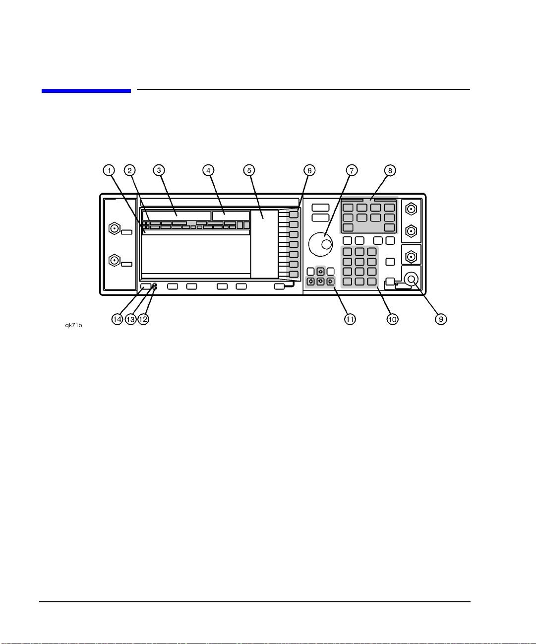
The Signal Generator at a Glance
The Signal Generator at a Glance
Refer to the figure and descriptions below as you use the procedures in this chapter. For
detailed front and rear panel information, refer to Chapter 2, “Exploring the User Interface.”
1. Active Entry Area. The current active function is
shown in this area.
2. Annunciators. These display annunciators show
the status of various signal generator functions.
3. Frequency Area. The current CW frequency is
shown in this portion of the display.
4. Amplitude Area. The current output power level is
shown in this portion of the display.
5 Softkey Labels. The softkey labels define the
functionsofthe corresponding softkeysimmediately
to the right of the labels.
6. Softkeys. Pressing a softkey activates the function
indicated by the label on the display directly to the
left of the softkey.
7. Knob. The knob is used to increase or decrease a
numeric value.
1-2 QuickStartGuide
8. Menu Keys. Thesehardkeys provide accessto the
signal generator’s primary functionality.
9. RF Output Connector. This female Type-N
connector is the output connector for RF signals.
10. Numeric Keypad. The numeric keypad consists of
digit, decimal point, and backspace keys. The
backspacekeycan alsobe used tochange thesign
of a numeric value.
11. Arrow Keys. Theup anddownarrow keys increase
or decrease numeric values. The left and right
arrow keys move the cursor.
12. Standby LED. This yellow LED lights when the
instrument is in standby mode.
13. Line Power LED. This green LED lights when
power is cycled on.
14. Power Switch. Pressing this hardkey toggles the
power between on and standby.
Page 5

ESG Family Signal Generators Getting Started
Creating an FM Signal
Creating an FM Signal
This procedure will show you how to configure the signal generator to output a
frequency-modulated signal with the following characteristics:
• carrier frequency set to 104.9 MHz
• power level set to 0 dBm
• FM deviation set to 75 kHz
• FM rate set to 10 kHz
Setting the Carrier Frequency
1. Press Preset. This sets the signal generator to its factory-defined instrument
state.
2. Press Frequency. Frequency becomes the active function and the preset value for
frequency is displayed in the active entry area.
3. Enter 104.9 using the numeric
keypad and press the MHz
softkey.
The new carrier frequency (104.900 000 00 MHz) is
shown in both the FREQUENCY area and the active entry area
of the display.
Setting the Power Level
1. Press Amplitude. Amplitude becomes the active function and the preset value for
amplitude is displayed in the active entry area.
2. Enter 0 using the numeric
keypad and press the dBm
softkey.
Quick Start Guide 1-3
The new power level (0.00 dBm) is shown in both the
AMPLITUDE area and the active entry area of the display.
Page 6

Getting Started ESG Family Signal Generators
Creating an FM Signal
Setting the FM Deviation
1. Press FM/φM. The first level menu of FM softkeys is displayed.
2. Press the FM Dev softkey. FM deviation becomes the active function and the preset value
for FM deviation is displayed in the active entry area.
3. Enter 75 using the numeric
keypad and press the kHz
softkey.
The new FM deviation is displayed below the FM Dev softkey.
You should see 75.0000 kHz in the second line of the
softkey label.
Setting the FM Rate
1. Press the FM Rate softkey. FM rate becomesthe activefunction andthe presetvaluefor FM
rate is displayed in the active entry area.
2. Enter 10 using the numeric
keypad and press the kHz
softkey.
The new FM rate is displayed below the FM Rate softkey. You
should see 10.0000 kHz in the second line of the softkey
label.
Turning On Frequency Modulation
The signal generator is now configured to output a 0 dBm, frequency-modulated carrier at
104.9 MHz with the FM deviation set to 75 kHz and the FM rate set to 10 kHz. The shape of
the waveform is a sinewave.
NOTE Sine is the default selection forthe FM Waveform softkey. Press More (1 of 2) to see
the softkey.
Follow these remaining steps to output the frequency-modulated signal:
1. Press the FM Off On softkey. FM toggles from Off toOn. Notice, also, that theFM display
annunciator is turned on, indicating that you have enabled
frequency modulation.
2. Press RF On/Off. Notice that the display annunciator changes fromRF OFF to
RF ON. The modulated signal is now available at the
RF OUTPUT connector.
1-4 QuickStartGuide
Page 7

ESG Family Signal Generators Getting Started
Creating a Step Sweep and a List Sweep
Creating a Step Sweep and a List Sweep
This section will show you two ways to set up the signal generator to sweep a defined set of
points. You will create a ten-point step sweep with the settings listed below, then use these
points as the basis for a new list sweep.
• frequency range from 525 MHz to 600 MHz
• power level from −20 dBm to 0 dBm
• dwell time 500 ms at each point
Configuring a Step Sweep
1. Press Preset. This sets the signal generator to its factory-defined instrument
state.
2. Press Sweep/List. The first level of sweep softkeys is displayed.
3. Press the Sweep Type List Step
softkey.
4. Press the Configure Step Sweep
softkey.
5. Press the Freq Start softkey.
Enter 525 using the numeric
keypad and press the MHz
softkey.
6. Press the Freq Stop softkey.
Enter 600 using the numeric
keypad and press the MHz
softkey.
7. Press the Ampl Start softkey.
Enter −20 using the numeric
keypad and press the dBm
softkey.
This toggles the Sweep Type List Step softkey from List to
Step.
Another menu is displayed with softkeys that you will use to
create the sweep points.
This setsthe new start frequencyforthe stepsweep to525 MHz.
This sets the new stop frequency for the step sweep to 600 MHz.
This sets the power level for the start of the step sweep to
−20 dBm.
Quick Start Guide 1-5
Page 8

Getting Started ESG Family Signal Generators
Creating a Step Sweep and a List Sweep
8. Press the Ampl Stop softkey.
Enter 0 using the numeric
This sets the new power level for the end of the step sweep to
0 dBm.
keypad and press the dBm
softkey.
9. Press the # Points softkey.
This sets the number of points in the step sweep.
Enter 10 by rotating the front
panel knob until the number
10 is displayed.
10. Press the Step Dwell softkey.
This sets the dwell time for each point in the step sweep.
Enter 500 using the numeric
keypad and pressing the msec
softkey.
Turning On Continuous Step Sweep
1. Press Return. This moves the softkey menu up one level.
2. Press the Sweep softkey. Another menu is displayed, showing you choices for sweeping
either the frequency, amplitude,or frequency andamplitude data.
3. Press the Freq & Ampl softkey. Selectingthis softkeyreturns you tothe previous menuandturns
the sweep function on.
4. Press the
Sweep Repeat Single Cont
softkey.
This toggles the Sweep Repeat Single Cont softkey from
Single to Cont (Continuous). Notice that theSWEEP display
annunciator is turned on, indicating that the signal generator is
sweeping.
5. Press RF On/Off. Notice that the display annunciator changes fromRF OFF to
RF ON. The swept RF signal is now available at the
RF OUTPUT connector.
1-6 QuickStartGuide
Page 9

ESG Family Signal Generators Getting Started
Creating a Step Sweep and a List Sweep
Configuring a List Sweep Using Step Sweep Data
1. Press the Sweep Type List Step
softkey.
2. Press the Configure List Sweep
softkey.
This toggles the Sweep Type List Step softkey from Step to
List.
Another menu is displayed with softkeys that you will use to
create the sweep points. Notice that the display shows the
current list data. (When no list has been previously created, the
default is one point set to the signal generator’s maximum
frequency, −135dBm, with a dwell time of 2 ms.)
3. Press the following softkeys:
More (1 of 2) >
Load List From Step Sweep >
Confirm Load From Step Sweep.
The points you defined in the step sweep are automatically
loaded into the list.
4. Press the More (2 of 2) softkey. This softkey menu along with the numeric keypad, arrow keys,
and front panel knob can be used to edit the sweep points in the
list. For more information about editing sweep points, refer to
Chapter 2, “Using Functions,” of the ESG Family Signal
Generators User’s Guide.
Quick Start Guide 1-7
Page 10

Getting Started ESG Family Signal Generators
Creating a Step Sweep and a List Sweep
Turning On List Sweep for a Single Sweep
1. Press Return. This moves the softkey menu up one level. Notice that the
Sweep softkeyis stillset tosweep both frequencyandamplitude
data.
2. Press the
Sweep Repeat Single Cont
softkey.
This toggles the Sweep Repeat Single Cont softkey from
Cont to Single. Notice that theSWEEP display annunciator is
turned off.
3. Press the Single Sweep softkey. The signal generator sweeps the points in your list once. Notice
that the SWEEP display annunciator is turned on during the
sweep.
4. Press the More (1 of 2) and
Sweep Trigger softkeys.
A menu isdisplayed showing youchoices fortriggering asweep.
Notice that you had used the default setting,Immediate, when
you triggered the single sweep in the previous step.
5. Press the Trigger Key softkey. This sets Sweep Trigger to Trigger Key and returns you to
the previous softkey menu.
6. Press the More (2 of 2) and
Single Sweep softkeys.
This arms the sweep so that it is ready for triggering. Notice that
the ARMED display annunciator is now turned on.
7. Press Trigger. The signal generator sweeps the points in your list once and the
SWEEP display annunciator appears during the sweep.
1-8 QuickStartGuide
Page 11

ESG Family Signal Generators Getting Started
Saving and Recalling an Instrument State
Saving and Recalling an Instrument State
Using thisprocedure, youwill learn howto saveinstrument settings toa memory register and
to recall the settings.
Creating an Instrument State
1. Press Preset. This sets the signal generator to its factory-defined instrument
state.
2. Press Frequency. Frequency becomes the active function and the preset value for
frequency is displayed in the active entry area.
3. Enter 800 using the numeric
keypad and press the MHz
softkey.
4. Press Amplitude. Amplitude becomes the active function, and the preset value for
5. Enter 0 using the numeric
keypad and press the dBm
softkey.
6. Press AM followed by the
AM Off On softkey.
The new carrier frequency (800.000 000 00 MHz) is
shown in both the FREQUENCY area and the active entry area
of the display.
amplitude is displayed in the active entry area.
The new power level (0.00 dBm) is shown in both the
AMPLITUDE area and the active entry area of the display.
AM toggles from Off toOn. Notice also that the AM display
annunciator is turned on, indicating that you have enabled
amplitude modulation. You have now created an example
instrument state that you will save and recall.
Quick Start Guide 1-9
Page 12

Getting Started ESG Family Signal Generators
Saving and Recalling an Instrument State
Saving an Instrument State
1. Press Save followed by the
Select Seq softkey.
2. Enter 1 using the numeric
keypad and press the Enter
softkey.
3. Press the Select Reg softkey. The registernumber insequence 1becomes theactive function.
4. Enter 1 using the numeric
keypad and press the
Select Reg softkey.
5. Press the SAVE Seq[1] Reg[01]
softkey.
The sequence number becomes the active function. The signal
generator displays the last sequence that you have used.
Thissets thesequence number to1. (You can alsouse thearrow
keys to enter the sequence number.)
The signal generator either displays the last register used
[accompanied by the text:(in use)] or, if no registers are in
use, displays register 00 [accompanied by the text:
(available)].
This selects register 01. (You can also use the arrow keys to
select the register number.)
The current instrument settings, including the frequency,
amplitude,and modulationchangesyou made,havebeenstored
in the signal generator memory.
Recalling an Instrument State
1. Press Preset. This sets the signal generator to its factory-defined instrument
state.
2. Press Recall. Notice that the Select Seq softkey shows sequence 1. (This is
the last sequence that youused.) You donot needto changethe
sequence.
3. Press the RECALL Reg softkey. The register to be recalled in sequence 1 becomes the active
function.
4. Enter 1 using the numeric
keypad and press the Enter
softkey.
1-10 QuickStart Guide
Notice that your stored instrument settings have been
immediately recalled. (You can also use the arrow keys to select
the register number.)
Page 13

ESG Family Signal Generators Getting Started
Setting Up a Digital Modulation in the GSM Format
Setting Up a Digital Modulation in the GSM Format
NOTE You must have an ESG-D or ESG-DP Series Signal Generator with Option UN8
to perform this procedure.
Using this procedure you will set up the signal generator to output a GMSK digitally
modulated signal in the GSM format with the following characteristics:
• carrier frequency set to 891 MHz
• power level set to −5 dBm
• timeslot 0 activated and configured as a Custom channel
• a fixed 4-bit repeating sequence selected as the data pattern for timeslot 0
• timeslot 7 activated and configured as a Normal channel
• 4 ones and 4 zeros selected as the data pattern for timeslot 7
Setting the Carrier Frequency
1. Press Preset. This sets the signal generator to its factory-defined instrument
state.
2. Press Frequency. Frequency becomes the active function and the preset value for
frequency is displayed in the active entry area.
3. Enter 891 using the numeric
keypad and press the MHz
softkey.
The new carrier frequency (891.000 000 00 MHz) is
shown in both the FREQUENCY area and the active entry area
of the display.
Setting the Power Level
1. Press Amplitude. Amplitude becomes the active function and the preset value for
amplitude is displayed in the active entry area.
2. Enter −5 using the numeric
keypad and press the dBm
softkey.
Quick Start Guide 1-11
The new power level (-5.00 dBm) is shown in both the
AMPLITUDE area and the active entry area of the display.
Page 14

Getting Started ESG Family Signal Generators
Setting Up a Digital Modulation in the GSM Format
Selecting the Data Format
1. Press Mode. Then press the
This selects the GSM communications standard.
following softkeys:
Real Time I/Q Baseband (if it
appears) > TDMA > GSM.
2. Press the
Data Format Pattern Framed
softkey.
This toggles the Data Format Pattern Framed softkey from
Pattern toFramed. When you select Framed for bursting the
frameenvelope,youwill betransmittingframed data. Thismeans
thatyou willbebursting thetimeslotsthat youhaveactivatedand
there will be no RF carrier during the off timeslots. Notice that
Configure Timeslots has become an active softkey.
Setting Up Timeslot 0
1. Observe the GSM Timeslot
Pattern on the display.
2. Press the Configure Timeslots
softkey andobserve thesoftkey
menu.
3. Press the Timeslot Type softkey. Another menu of softkeys is displayed.
Notice that the preset condition for timeslot #0 has the timeslot
turned on and configured as a Normal channel.
The Timeslot # softkey shows that timeslot #0 is selected as
the active timeslot. TheTimeslot Off On softkey shows that
timeslot #0 is turned on. Finally, theTimeslot Type softkey
shows that timeslot #0 is configured as a Normal channel.
4. Press the Custom softkey. This changes the timeslot type to Custom timeslot and
automatically returns you to the previous softkey menu. Notice
that the Timeslot Type softkey has changed fromNormal to
Custom. Also notice that the display shows timeslot#0
configured as a Custom timeslot.
5. Press the Configure Custom
softkey.
Another menu is displayed showing you data choices for the
timeslot’s transmission. Notice that the display has changed,
showing you a visual representation of the timeslot. Directly
below the visual representation of the timeslot, you should see
Data: PN9. PN9 is the default timeslot transmission data.
1-12 QuickStart Guide
Page 15

ESG Family Signal Generators Getting Started
Setting Up a Digital Modulation in the GSM Format
6. Press the FIX4 softkey. This changes the transmitted data to a fixed 4-bit repeating
sequence. The default 4-bit repeating sequence of0000 is
shown in the active entry area of the display.
7. Enter 1010 using the numeric
keypad and press the Enter
softkey.
This changes the pattern from 0000 to 1010. Directly below the
visual representation of the timeslot, you should see
Data: 1010.
Setting Up Timeslot 7
1. Press Return. This moves the softkey menu up one level.
2. Press the Timeslot # softkey.
Then enter 7 using the numeric
keypad and press the Enter
softkey.
3. Press the Timeslot Off On
softkey.
4. Press the Timeslot Type softkey. Another menu of softkeys is displayed.
5. Press the Normal softkey. This changes the timeslot type to a Normal timeslot and
This selectstimeslot #7as theactive timeslot.(You canalso use
thearrowkeys to selectthetimeslots.)The currentactive timeslot
(#7) is displayed in the active entry area.
This toggles the Timeslot Off On softkey fromOff to On.
Notice that the display now shows that timeslot#7 is turned on.
automatically returns you to the previous softkey menu. Notice
that the Timeslot Type softkey has changed fromCustom to
Normal. Also notice that the display shows timeslot#7
configured as a Normal timeslot.
6. Press the Configure Normal
softkey.
7. Press the following softkeys:
E > Other Patterns > 4 1’s & 4 0’s.
Another menu of softkeys is displayed, allowing you to change
the E, S, and TS fields for the Normal timeslot.
Thisfills theE field witha repeatingsequenceof four1’s followed
by four 0’s. Directly below the visual representation of the
timeslot, you should see E: P4.
Quick Start Guide 1-13
Page 16

Getting Started ESG Family Signal Generators
Setting Up a Digital Modulation in the GSM Format
Turning On the GSM Format and the Modulation
The signal generator is now configured to burst twouplink timeslots with a −5.0 dBm, GMSK
digitally modulated carrier at 891 MHz. Follow these remaining steps to output the framed
data.
1. Press Return twice. This moves the softkey menu up two levels. The first GSM
softkeymenu shouldbe displayed. (Thefirst softkey inthis menu
is GSM Off On.)
2. Press the GSM Off On softkey. This toggles the GSM Off On softkey fromOff to On. At this
time the internal baseband generatorgenerates theinternal data
patterns that you have configured for timeslots 0 and 7.
Amessage isdisplayedwhile thisprocess istaking place. Notice
also that the following display annunciators are turned on:
• GSM indicates that you have enabled the GSM standard.
• I/Q indicates that I/Q modulation is being generated.
• ENVLP indicates that burst is activated for transmitting
framed data.
3. Press RF On/Off. Notice that the display annunciator changes fromRF OFF to
RF ON. The modulated signal is now available at the
RF OUTPUT connector.
1-14 QuickStart Guide
Page 17

ESG Family Signal Generators
2 Exploring the User Interface
This chapter provides you with an overview of your signal generator’s user interfaces:
• front panel hardkeys and connectors
• display fields and annotations
• rear panel connectors
Quick Start Guide 2-1
Page 18

Exploring the User Interface ESG Family Signal Generators
Front Panel
Front Panel
The following pages describe the numbered items shown in the figure below.
2-2 QuickStartGuide
Page 19

ESG Family Signal Generators Exploring the User Interface
Front Panel
1. EXT 1 INPUT This female BNC input connector accepts a 1-V
signal for FM,
pk
ΦM, and AM.
2. EXT 2 INPUT This female BNC input connector accepts a 1-V
signal for FM,
pk
ΦM, AM, and pulse modulation.
3. Help Press this hardkey for a short textual description of the function of
the front panelhardkeys and softkeys. Pressthis key again and you
will be returned to normal instrument operation.
4. Trigger Press this hardkey to begin an event (such as a step or list sweep).
This keymust first beselected as the method foractivating an event
by pressing the Trigger Key softkey, located in the softkey menus
associated with the event.
5. LF OUTPUT This female BNC connector is the output connector for modulation
signals generated by the LF (low frequency) source function
generator.
6. Mod On/Off This hardkey toggles all modulation signals on and off.
7. RF OUTPUT This female Type-N connector is the output connector for RF
signals.
8. RF On/Off This hardkey toggles the RF signal on and off at the RF OUTPUT
connector.
9. Numeric
Keypad
The numeric keypad consists of the digit keys (0 through 9), a
decimal point key, and abackspace key. The backspacekey has dual
functions for both backspacing and changing the sign of a value
between positive and negative. Use these keys whenever the active
function requires a value input.
10. Arrow Keys The up and down arrow keys increase or decrease a numeric value.
You can alsouse these keysto scroll throughdisplayed lists toselect
items. The left and right arrow keys choose the highlighted digit in
the activeentry area ofthe display; thatdigit can bemodified by the
up and down arrowkeys or the knob. You can also use these keys in
a list to select items in a row.
Quick Start Guide 2-3
Page 20

Exploring the User Interface ESG Family Signal Generators
Front Panel
11. Return The Return key cancels the current active function and moves you
from your current softkey menu to the softkey menu that precedes
it.
12. Display
Contrast
Decrease
13. Display
Contrast
Increase
14. Local Press this key to return the signal generator to local (front panel)
Press this key and hold it down to cause the display background to
darken in comparison to the text on the display.
Press this key and hold it down to cause the display background to
brighten in comparison to the text on the display.
control from remote operation.
15. Preset Press this key to set the signal generator to a known state (either
the factory-defined state or a user-defined state).
16. Standby LED This yellow LED lights when the instrument is in standby
condition. In standby, the power switch is off but the instrument is
still connected to the main power circuit by way of the power cord.
17. Line Power
LED
18. Power Switch Press this hardkey to turn power to the signal generator either on
This green LED lights when power is cycled on to the signal
generator.
(green LED on) or to standby (yellow LED on).
19. Q INPUT This connector accepts an externally supplied, analog,
quadrature-phase component of I/Q modulation. This female BNC
connector is provided only on ESG-D and ESG-DP Series Signal
Generators.
20. I INPUT This connector accepts an externally supplied, analog, in-phase
component of I/Q modulation. This female BNC connector is
provided only on ESG-D and ESG-DP Series Signal Generators.
2-4 QuickStartGuide
Page 21

ESG Family Signal Generators Exploring the User Interface
Front Panel
21. Display The LCD display provides information on the current instrument
state such as modulation status, frequency and amplitude settings,
status indicators, and error messages. Softkey labels corresponding
to their adjacent keys are located on the right-hand side of the
display.
22. Hold Press this hardkey to deactivate the currently active function and
blank the softkeymenu. Once Hold ispressed, the front panel knob,
the arrow keys, and the numerickeypad have no effect. To return to
normal operation, press a function or menu hardkey.
23. Softkeys Press a softkey to activate the function indicated by the
corresponding label on the display.
24. Knob The knob increases or decreases a numeric value. Any of the values
that can be set through the numeric keypad or the step keys can
also be set with the knob.
25. Amplitude Press thishardkey to activatethe power level amplitudefunction so
that you can change the amplitude of the RF output.
26. Frequency Press this hardkey to activate the frequency function so that you
can change the frequency of the RF output.
27. Save This hardkey lets you save up to 100 different instrument states in
a combination of 100 memory registers and 10 register sequences.
The number of states you can save, however, is limitedby the size of
whatever else is stored in the file system.
28. Menu Keys These hardkeys provide access to the signal generator’s primary
functionality. Press these keys for access to softkey menus where
you can configure modulations, step and list sweeps, and various
frequency and power capabilities.
29. Incr Set Press thishardkey totoggle betweenthe current activefunction and
the increment size for that function. With increment size selected,
you can change the current increment value.
Quick Start Guide 2-5
Page 22

Exploring the User Interface ESG Family Signal Generators
Front Panel
30. Recall This hardkey lets you restore any instrument state that you
previously saved in a memory register. You can save up to 100
different instrument states in a combination of 100 memory
registers and 10 register sequences. The number of states you can
save, however, is limited bythe size of whatever elseis stored in the
file system.
31. DATA Input The TTL/CMOS-compatible DATA connector accepts an externally
supplied data inputfor digital modulation applications.This female
BNC connector is provided only on instruments with Option UN8.
32. DATA CLOCK
Input
The TTL/CMOS-compatible DATA CLOCK connector accepts an
externally supplied data-clock input for digital modulation
applications. This female BNC connector is provided only on
instruments with Option UN8.
33. SYMBOL SYNC
Input
The CMOS-compatible SYMBOL SYNC connector accepts the
digital-modulation symbol synchronization signal from an external
source. This female BNC connector is provided only on instruments
with Option UN8.
34. PULSE IN Thisconnector accepts anexternally supplied TTL-compatiblepulse
signal. The pulse signal is activated with the Fast Pulse Off On
softkey or via SCPI command. The maximum input for this
connector is ±15 volts. This female BNC connector is provided only
on instruments with Option 1E6.
2-6 QuickStartGuide
Page 23

ESG Family Signal Generators Exploring the User Interface
Display
Display
The following pages describe the numbered items shown in the figure below.
1. Frequency
Area
2. Amplitude Area The current output power level setting is shown in this portion of
3. Softkey Labels These labels define the function of the corresponding softkeys
Quick Start Guide 2-7
The current CW frequency setting is shown in this portion of the
display.
the display.
immediately to the right of the label.
Page 24

Exploring the User Interface ESG Family Signal Generators
Display
4. Error Messages
Area
Abbreviated error messages are reported in this space. When
multiple error messages occur, only the most recent message
remains displayed. All of the reported error messages with details
can be viewed by pressing Utility > Error Info >
View Next Error Message.
5. Text Area This area is used to display status information about the signal
generator such as the modulation status, to enter information such
as creating sweep lists, and to manage information such as
displaying the catalog of files and deleting unwanted files.
6. Active Entry
Area
The current active function is shown in this area. For example, if
frequency is the active function, the current setting will be
displayed in the active entry area and that setting will change as
you enter a new value.
7. Annunciators The display annunciators show the status of some of the signal
generator functions andindicate error conditions ofthe instrument.
The following annunciators are available:
φM This annunciator appears when phase modulation is turned on.
ALC OFF This annunciator appears when the automatic leveling control
(ALC) circuit is disabled.
AM This annunciator appears when amplitude modulation is turned on.
ARMED This annunciator appears when a sweep has been initiated and the
signal generator is waiting for the sweep trigger event.
ATTEN HOLD This annunciator appears when the attenuator hold function is
turned on. When this function is on, the attenuator is frozen at its
current setting.
BERT This annunciator appears whenever the Option UN7, bit error rate
test (BERT), or Option 300,base station BERT extension, functions
are turned on.
Digital
Modulation
Annunciators
An annunciator appears here when a digital modulation is on.
The exact annunciator depends on the modulation type, and is
documented in the manual that addresses that modulation.
Only one modulationcon be on at a time, so sharing an annunciator
location is not a problem.
2-8 QuickStartGuide
Page 25

ESG Family Signal Generators Exploring the User Interface
Display
ENVLP This annunciator appears if the burst envelope modulation is
turned on. This annunciator is present only on ESG-D and ESG-DP
Series Signal Generators.
ERR This annunciator appears when an error message is placed in the
error queue.This annunciator will notturn off until youhave either
viewed all of the error messages or cleared the error queue.You can
view and delete error messages using the Utility menu.
EXT1 LO/HI This annunciator toggles between EXT1 LO and EXT1 HI. This
annunciator appears if the AC-coupled signal to the EXT 1 input is
less than 0.97 Vpk or greater than 1.03 Vpk.
EXT2 LO/HI This annunciator toggles between EXT2 LO and EXT2 HI. This
annunciator appears if the AC-coupled signal to the EXT 2 input is
less than 0.97 Vpk or greater than 1.03 Vpk.
EXT REF This annunciator appears when an external 1, 2, 5, or 10 MHz
frequency reference is in use.
FM This annunciator appears when frequency modulation is turned on.
I/Q This annunciator appears when I/Q modulation is turned on. This
annunciator is present only on ESG-D and ESG-DP Series Signal
Generators.
L The L annunciator is turned on when the signal generator is in the
listen mode and is receiving information or commands over the
GPIB or RS-232.
MOD OFF This annunciator toggles between MOD OFF and MOD ON and is
always visible in the display. This annunciator indicates whether
the modulations that you have enabled are modulating the RF
carrier.
OVEN COLD This annunciator appears when the temperature of the internal
ovenized reference oscillator (ESG-AP, ESG-DP, and Option 1E5)
has dropped below an acceptable level.
PULSE This annunciator appears when pulse modulation is turned on.
R The R annunciator appears when the signal generator is in remote
GPIB operation.
Quick Start Guide 2-9
Page 26

Exploring the User Interface ESG Family Signal Generators
Display
RF OFF This annunciator toggles between RF OFF and RF ON and is
always visible in the display. This annunciator indicates whether
the RF signal is present at the RF OUTPUT connector.
S The S annunciator appears when the signal generator has
generated a service request (SRQ) over the GPIB.
SWEEP This annunciator appears when the signal generator is sweeping in
list or step mode.
T The T annunciator appears when the signal generator is in the talk
mode and is transmitting information over the GPIB or RS-232.
2-10 QuickStart Guide
Page 27

ESG Family Signal Generators Exploring the User Interface
Rear Panel
Rear Panel
The following pages describe the numbered items shown in the figure below.
1. AC Power
Receptacle
2. GPIB The GPIB connector allows communications with compatible
3. SYMBOL SYNC
OUT
Quick Start Guide 2-11
The power cord receptacle accepts a three-pronged cable that is
shipped with the instrument. The line voltage is connected here.
devices such as external controllers. It is functionally equivalent to
the AUXILIARY INTERFACE connector.
The TTL/CMOS-compatible SYMBOL SYNC OUT connector
outputs a symbolsynchronization pulse, one data-clock period wide,
for use in digital modulation applications. This female BNC
connector is present only on instruments with Options UND or
UN8. With Option 201 you can select from several different output
signals for this connector.
Page 28

Exploring the User Interface ESG Family Signal Generators
Rear Panel
4. AUXILIARY
INTERFACE
This male DB-9 connector is an RS-232 serial port that can be used
for controlling the signal generator remotely. It is functionally
equivalent to the GPIB connector.
5. DATA CLK OUT The TTL/CMOS-compatible DATA CLK OUT connector outputs a
clock signal for digital modulation data. Thisfemale BNC connector
is present only on instruments with Options UND or UN8. With
Option 201 you can select from several different output signals for
this connector
6. SWEEP OUT This female BNC connector provides a voltage range of 0 to +10 V.
When the signal generator is sweeping, the SWEEP OUT signal
ranges from 0 V at the beginning of the sweep to +10 V at the endof
the sweep regardless of the sweep width.
7. DATA OUT The TTL/CMOS-compatible DATA OUT connector outputs digital
modulation data sourced from an externally supplied signal at the
DATA input or from the internal pattern generator. This female
BNC connectoris presentonly on instrumentswith Options UNDor
UN8. With Option 201 you can select from several different output
signals for this connector.
8. TRIGGER OUT This female BNC connector outputs a TTL signal that is asserted
high at the start of a dwell sequence, or at the start of waiting for
the point trigger in manual sweep mode, and low when the dwell is
over, or when the point trigger is received, or once per sweep during
an LF sweep.
9. TRIGGER IN This female BNC connector acceptsa TTLsignal for triggering, such
as point-to-point in manual sweep mode or an LF sweep in external
sweep mode.
10. 10 MHz IN This female BNC connector accepts a −3.5 to +20 dBm signal from
an external timebase reference that is within 10 ppm (standard
timebase) or 1 ppm (high stability timebase).
11. 10 MHz OUT This female BNC connector provides a nominal signal level of
+7 dBm ±2 dB, and an output impedance of 50Ω. The accuracy is
determined by the timebase used.
2-12 QuickStart Guide
Page 29

ESG Family Signal Generators Exploring the User Interface
Rear Panel
12. PATTERN
TRIG IN
This inputcan accepteither a TTL/CMOSlow toTTL/CMOS high or
TTL/CMOS high to TTL/CMOS low edge trigger. With Option UN8
this inputtriggers theinternal digitalmodulation patterngenerator
to start a single pattern output or to stop and re-synchronize a
pattern that is being continuously output. With Option UND this
input is the external trigger source for all ARB waveform generator
triggers. With Option 201 this connector is used for system reset
trigger input.
13. BURST GATE
IN
The BURST GATE IN connector accepts a TTL or CMOS signal for
gating burst power in digital modulation applications. This female
BNC connectoris presentonly on instrumentswith Options UNDor
UN8. With Option 201 this connector is used for even second
synchronization input.
14. COHERENT
CARRIER OUT
This connector outputsRF that is not modulated with AM, pulse, or
I/Q modulation, but that is modulated with FM or ΦM. This SMA
connector is present only on ESG-D and ESG-DP Series Signal
Generators.
15. ALT PWR IN This BNC connector accepts a CMOS signal for synchronization of
external data and alternate power signal timing. This connector is
active only with Options UNA or 201. With Option 201 this
connector is used for Long Code State Latch strobe input.
16. EVENT 1 With Option UN8 turned on, this TTL/CMOS-compatible connector
outputs a pulse that can be used to trigger the start of a data
pattern, frame, or timeslot. With Option UN5 turned on, an even
second output is generated every two seconds indicating the
beginning ofeach short codesequence. WithOption UNDturned on,
a marker is output whenever a Marker 1 is turned on in the
waveform. With Option 201 you can select from several different
output signals for this connector.
17. EVENT 2 This TTL/CMOS-compatible connector outputs a dataenable signal
for gating external equipment. With Option UN5 turned on, a
marker is output every 26.67 ms, corresponding to the start of each
short code. With Option UND turned on, a marker is output
whenever a Marker 2 is turned on in the waveform. With
Option 201 this connector is used for system reset output.
Quick Start Guide 2-13
Page 30

Exploring the User Interface ESG Family Signal Generators
Rear Panel
18. BASEBAND
GEN REF IN
With OptionUN8 enabled, theBASEBAND GENREF IN connector
accepts a 0to +20 dBm sinewave or TTL squarewave signal from an
external 13-MHz timebase reference. This female BNC connector is
present only on instruments with Options UND or UN8.
19. I OUT The I OUT connectoroutputs the analog, in-phase component of I/Q
modulation from theinternal baseband generator. This female BNC
connector is present only on instruments with Options UND or
UN8.
20. Q OUT The Q OUT connector outputs the analog, quadrature-phase
component of I/Q modulationfrom the internal baseband generator.
This female BNC connector is present only on instruments with
Options UND or UN8.
21. BER MEAS
END
The BER MEAS END connector outputs a signal that indicates the
status of the bit-error-rate (BER) measurements. This female SMB
connector is present only on instruments with Option UN7.
22. BER TEST OUT The BER TEST OUT connector outputs a signal that indicates the
test result of the pass/fail judgement of the bit-error-rate
measurements. This female SMB connector is present only on
instruments with Option UN7.
23. BER ERR OUT The output of the BER ERR OUT connector is normally low. When
the maximum data rate mode is set to 2 Mbps, the BER ERR OUT
connector outputs pulse signals that indicate errors. This female
SMB connector is present only on instruments with Option UN7.
24. BER NO DATA The BER NO DATA connector outputs a signal that indicates the
“no data” status. Theno data status is reportedwhen therehas been
no clock input for more than 3 seconds or there has been no data
change for more than 200 bits. This female SMB connector is
present only on instruments with Option UN7.
25. BER SYNC
LOSS
The BER SYNC LOSSconnector outputs a signal that indicates the
synchronization loss state. This female SMB connector is present
only on instruments with Option UN7.
2-14 QuickStart Guide
Page 31

ESG Family Signal Generators Exploring the User Interface
Rear Panel
26. BER DATA IN Use this connector to input the data streams for the bit-error-rate
measurements. This female BNC connector is present only on
instruments with Option UN7.
27. BER CLK IN Use this connector to input the clock signal for the bit-error-rate
measurements. This female BNC connector is present only on
instruments with Option UN7.
28. BER GATE IN Use this connector to input the clock gate signal for the
bit-error-rate measurements. The connector can be enabled or
disabled by a softkey or an GPIB command. This female BNC
connector is present only on instruments with Option UN7.
29. 321.4 MHz IN Use this connectorto inputa downconverted 321.4MHz GSMsignal
for base transceiver station (BTS) loopback measurements. This
female SMB connector is present only on instruments with
Option 300.
Quick Start Guide 2-15
 Loading...