

Page 1
Agilent Technologies
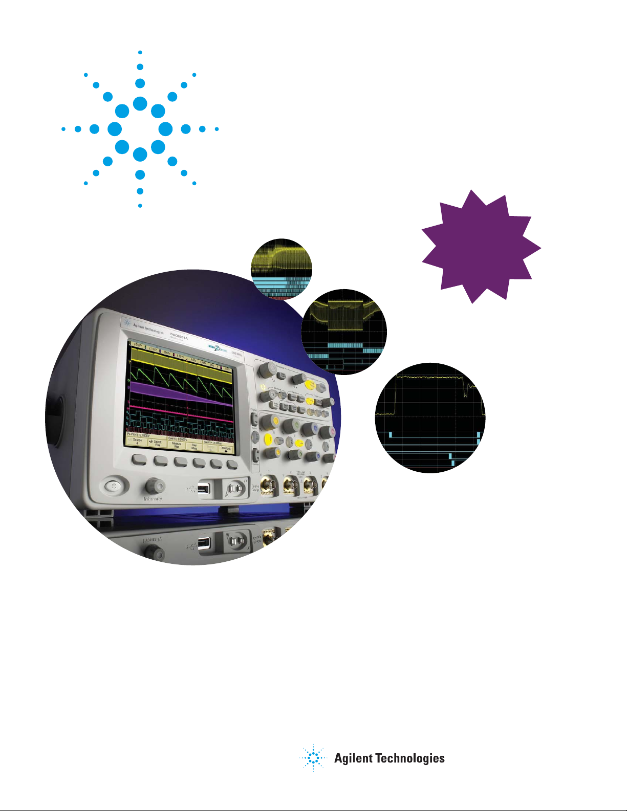
6000 Series Oscilloscopes
Data Sheet
MORE
The new Agilent 6000 Series oscilloscopes deliver more powerful features
and higher performance than any other scopes in their price range.
lab scope performance
at a
portable scope price
NEW
I
2
C/SPI,
CAN/LIN Bus
Decode Options
Available
Page 2
2
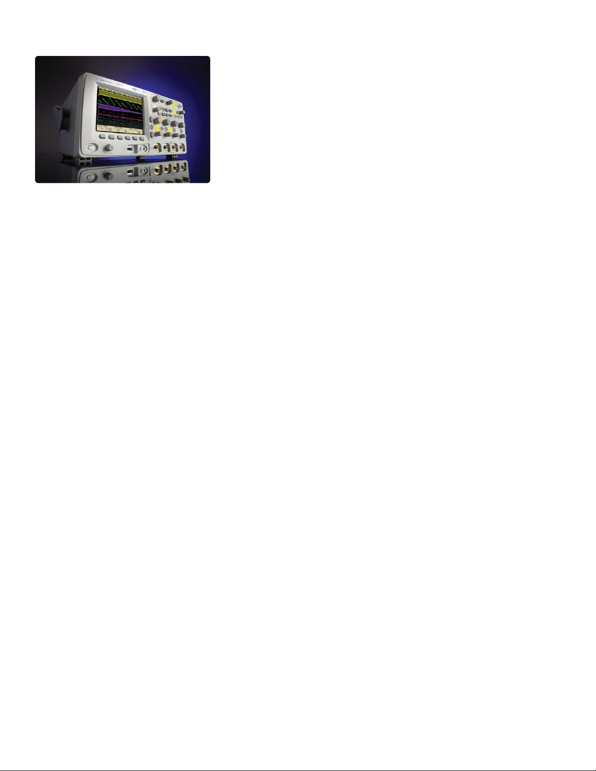
The performance and
problem-solving tools you need
to meet your mixed analog and
digital design challenges, today
and tomorrow
• A variety of models optimized to
meet your needs:
• 100 MHz, 300 MHz, 500 MHz
and 1 GHz bandwidth
• Up to 4 GSa/s sample rate
• Unique 2+16-channel,
4+16-channel mixed signal
oscilloscope (MSO) and 2- or
4-channel digital storage
oscilloscope (DSO) models
• Industry-leading performance:
• Standard 1 Mpts
MegaZoom III deep memory;
up to 8 Mpts optional
• High-definition XGA
(1024 x 768) color display
system with ultra-fast
real-time update rate of up
to 100,000 waveforms/sec
and 256 intensity levels
• Flexibility to upgrade a DSO
to an MSO at any time
• Full-scale connectivity –
Standard USB, LAN,
GPIB and XGA video output
• Powerful triggering including
analog HDTV, CAN, I2C, LIN,
SPI, and USB
• AutoProbe interface
• Built-in help system in
six languages
• NEW I2C/SPI, CAN/LIN bus
decode options
Bring your toughest problems into
focus with the right combination of
features and performance
If you work with both analog
and digital circuitry, Agilent
Technologies 6000 Series
oscilloscopes can help you easily
see more signal activity in your
designs. The unique 2+16- or
4+16-channel mixed signal
oscilloscope (MSO) models and
the traditional 2- and 4-channel
digital storage oscilloscope
(DSO) models are optimized
with the capabilities you need
for verifying and debugging
designs that include embedded
microcontrollers, DSPs, FPGAs,
ADCs, DACs, and transducers.
These scopes give you the tools
you need to solve your mixed
analog and digital engineering
challenges more easily.
Ideal for mixed analog and
digital signal analysis
The 6000 Series scopes combine
a suite of essential features that
are ideal for analyzing designs
with both analog and digital
components:
• 1 Mpts of Agilent’s third
generation MegaZoom III
deep memory captures long,
non-repeating signals and
maintains high sample rates,
allowing you to quickly
zoom in on areas of interest.
Optional 2 Mpts and 8 Mpts
memory lets you capture fast
and elusive signal problems
over even longer periods of
acquisition time.
• A revolutionary ultra-responsive,
high-definition color display
lets you see more signal details
than ever before. The 100,000
waveforms/sec real-time
waveform update rate is more
than 27 times faster than that
of a typical digital scope in
this class.
• Three standard interfaces:
high-speed USB2.0 device,
10/100 Base-T LAN (Ethernet),
and GPIB interfaces allow you
to easily save your waveform
data or images to your PC. You
can print the waveforms on a
connected printer or connect a
USB flash drive (or other USB
mass storage device) to the
USB 1.1 host port on the front
or the rear of the oscilloscope.
• Flexible triggering lets you
easily isolate and analyze the
complex signals and fault
conditions common in mixed
analog and digital designs. I2C,
CAN, LIN, USB, SPI and video,
including analog HDTV/EDTV,
triggering come standard.
• When your needs change, you
can upgrade your DSO6000
Series scope to an MSO with
the addition of a scope logic kit
that you can install yourself.
This combination of capabilities
is tailored to give you the
measurement power you need
to get your mixed analog and
digital job done faster.
Page 3
3
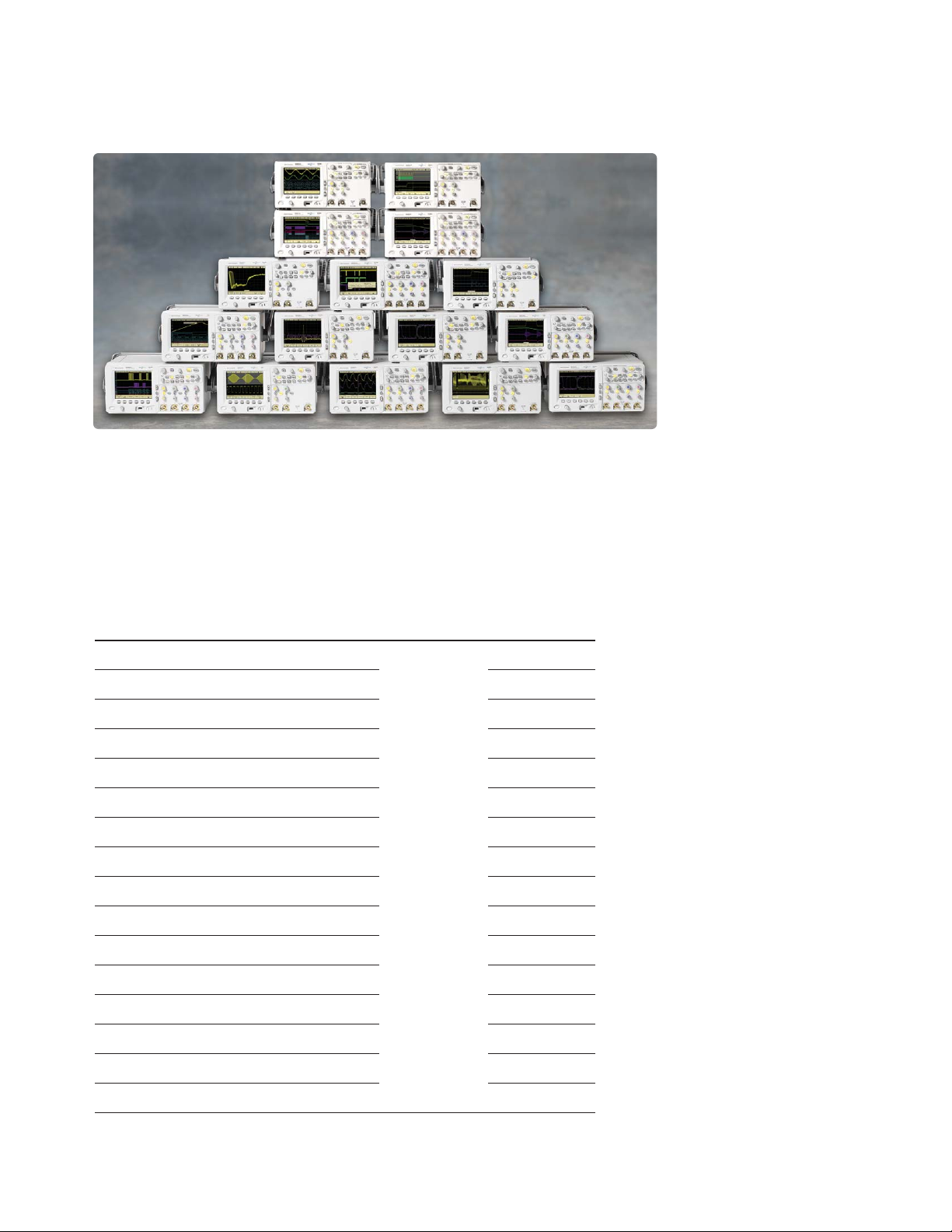
Selection guide
Figure 1. The 6000 Series
family shown with
2+16-channel, 4+16-channel
MSO and 2- and 4-channel
DSO models.
Agilent focuses on developing products that help you do your job
better. Agilent’s 6000 Series scopes are optimized for your
measurement needs. Choose the one that’s right for your application
and your budget.
Selection guide
Maximum
Model Bandwidth sample rate Memory Channels
DSO6012A 100MHz 2GSa/s 2 scope
MSO6012A 100MHz 2GSa/s 2 scope + 16 logic
DSO6014A 100MHz 2GSa/s 4 scope
MSO6014A 100MHz 2GSa/s 4 scope + 16 logic
DSO6032A 300MHz 2GSa/s 2 scope
MSO6032A 300MHz 2GSa/s 2 scope + 16 logic
DSO6034A 300MHz 2GSa/s 4 scope
MSO6034A 300MHz 2GSa/s 4 scope + 16 logic
DSO6052A* 500MHz 4GSa/s 2 scope
MSO6052A* 500MHz 4GSa/s 2 scope + 16 logic
DSO6054A* 500MHz 4GSa/s 4 scope
MSO6054A* 500MHz 4GSa/s 4 scope + 16 logic
DSO6102A* 1GHz 4GSa/s 2 scope
MSO6102A* 1GHz 4GSa/s 2 scope + 16 logic
DSO6104A* 1GHz 4GSa/s 4 scope
MSO6104A* 1GHz 4GSa/s 4 scope + 16 logic
* Maximum sample rate and memory are achieved when 2 channels are interleaved.
MegaZoom III
1 Mpts standard,
2 Mpts and
8 Mpts optional
Agilent responded to customer
inputs and we are proud to present
these additional reasons to buy
the new Agilent 6000 Series.
New Agilent 6000 Series =
older Agilent 54620/40 Series PLUS
+ 4/4+16 channel models and
1 GHz models
+ 2x - 10x sampling rate (up to
4 GSa/s scope and 2 GSa/s logic)
+ MSO-upgradeable DSOs
+ MegaZoom III deep memory
combining fast and deep
memory, new ultra-high
definition color LCD display
with XGA resolution and 256
levels of intensity
+ Faster waveform update rates
(100,000 waveforms/sec)
+ Standard analog HDTV/EDTV,
Nth edge burst and either edge
triggering
+ Built-in front panel USB port
replaces floppy drive
+ Standard USB, LAN and GPIB
+ XGA video output
+ AutoProbe interface (on
300 MHz - 1 GHz models)
+ 10 MHz reference clock in/out
+ Signal frequency feedthrough
+ 8-digit hardware frequency
counter (when using external
10 MHz reference input)
+ Built-in storage compartment
+ Lighter weight
Page 4
4
Selection guide (continued)
Easily see complex interactions with
2+16-channel or 4+16-channel
mixed signal oscilloscopes
(models MSO6000A)
The mixed signal oscilloscopes
(MSOs), with 2 or 4 scope
channels plus 16 logic channels,
uniquely combine the detailed
signal analysis of a scope
with the multi-channel timing
measurements of a logic analyzer.
They let you see the complex
interactions among your signals
on up to 20 channels at the same
time. No more guesswork and no
more poking around to see a few
channels at a time. These scopes
can easily conquer mixed analog
and digital debugging problems
that a traditional scope can’t
begin to address, because they let
you simultaneously test and
monitor the high-speed digital
control signals and the slower
analog signals in your design.
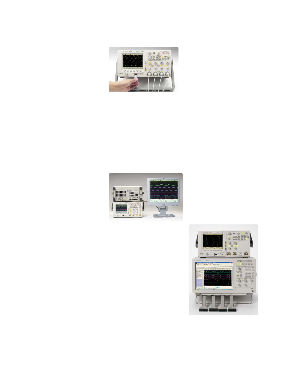
Figure 2. The 4+16-channel MSO allows
you to view up to 4 analog and 16 digital
signals on one instrument.
2- or 4-channel DSOs (model
DSO6000A) – scopes that can
grow with your needs
If your designs include heavy
analog content, the DSO6000A
will give you the number of
channels and measurement
power you need, including
MegaZoom III deep memory,
high-definition display, and
flexible triggering. Whether
you’re testing designs with four
inputs, such as anti-lock brakes,
or monitoring multiple outputs
of a power supply, the 4-channel
models help you perform your
debug and verification with ease.
If you don’t need 4 channels and
good value is a primary concern,
the 2-channel models provide
you with all the benefits of
MegaZoom III deep memory,
high-definition display, and
flexible triggering. They give you
an affordable way to see long
time periods while maintaining a
high sample rate so you can see
details in your designs.
After-purchase upgrade options
You can expand the capabilities
of all 6000 models whenever you
choose. You can easily upgrade
your DSO to include the 16 timing
channel MSO capabilities or
choose a memory upgrade
option to 2 Mpts and 8 Mpts
for increasing the acquisition
memory depth on your scope
after purchase. The upgrade is
easy and affordable.
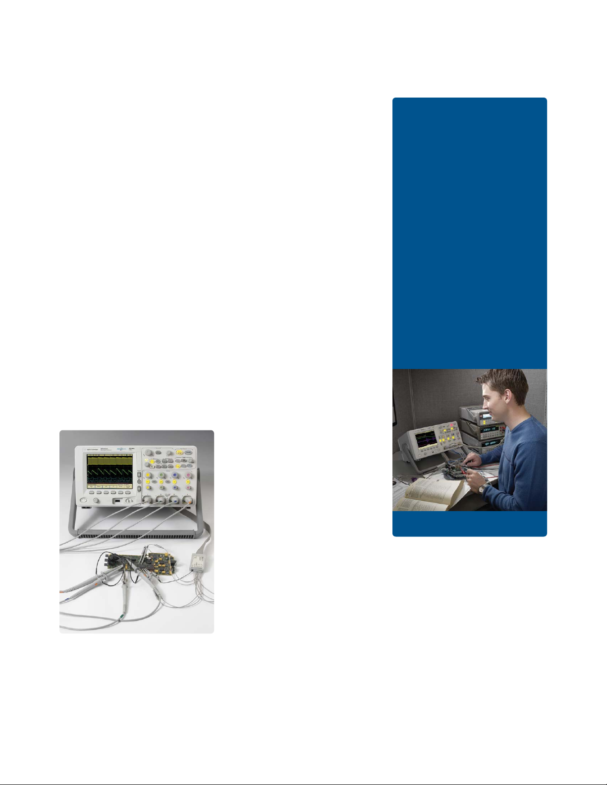
Try a new MSO6000A MSO
for yourself
There is no better way to
experience the superiority of
the new Agilent 6000 Series
scopes than seeing one in
action on your bench to
measure your signals
yourself. We can arrange
for you to try out a new
MSO6000A MSO. Contact
your nearest Agilent
sales office or visit the
MSO6000A home page at
www.agilent.com/find/
MSO6000. Contact Agilent
today to request an evaluation.
Page 5
5
Industry-leading performance
MegaZoom III deep memory
With many of today’s designs
containing a mix of signal
types and speeds, it’s often
critical to capture and compare
multiple cycles of digital signals
along with slower analog signals.
But doing so often requires an
instrument that can deliver more
resolution and memory than a
traditional DSO can provide.
Agilent pioneered the patented
MegaZoom approach beginning
with products introduced in 1996
and continued to improve it with
the 54600 Series introduced in
2000 and 2002. MegaZoom III as
implemented in the new 6000
Series products presents the most
advanced use of deep memory
and precision displays ever.
With up to 8 Mpts of MegaZoom
III deep memory, now you can
correlate high-speed digital
control signals with slower analog
signals, capture infrequent events
and then quickly zoom in on the
details to narrow in on problems.
Unlike deep-memory options
on alternative scopes, Agilent
MegaZoom III is not a special
mode with sluggish response.
It’s always on, always fast, and
always there to help you capture
the most critical signals with
maximized sample rates. The
6000 Series scopes are the only
deep-memory scopes in their
class that respond instantly to
your control inputs with a fast,
high-definition display. Compare
them to other scopes in this price
range – only the 6000 Series
provides deep memory at an
affordable price.
I. Most responsive deep memory
II. Highest definition color display
III. Fastest waveform update rate,
uncompromised
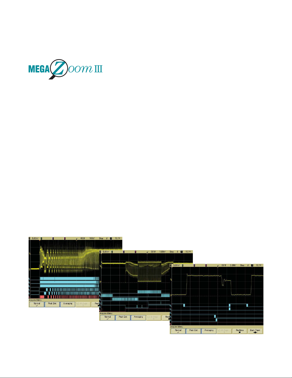
Five ways deep memory gives you
better insight into your design
1. Deep memory allows the scope
to maintain faster sample rates
(or shorter sampling intervals
between digitized points), even
at slow time base settings.
2. At a given time base setting,
deeper memory makes it
possible to capture signals with
finer resolution. And at a given
sample rate, it lets you capture
more time on your signals.
3. Deep memory helps you
find details buried in
complex signals.
4. Deep memory helps you
discover anomalies in
the absence of precise
triggering events.
5. Deep memory is particularly
valuable when you are dealing
with mixed analog and digital
designs where slow analog
events require long time spans
and fast digital control signals
require the ability to maintain
high sample rate.
Figure 3. Motor drive signal start-up sequence with digital control signal triggering and various levels of zoom reveal “runt” pulse
using Agilent’s MSO6000A Series MSOs.
Page 6
6
Industry-leading performance (continued)
Revolutionary high-definition color
display helps you see subtle
details that most scopes can’t
show you
Combine MegaZoom III
deep memory with an ultra
high-definition color display
system, and you will see subtle
details that most scopes won’t
show you. The MegaZoom III deep
memory is mapped to 256 levels
of intensity on a display that has
industry-leading XGA resolution
(1024 x 768 lines) and phenomenal
waveform update rates of up to
100,000 waveforms per second in
the default real-time acquisition
mode – so you see a more realistic
representation of your signals.
With fast waveform update rates,
your scope has less dead time
between the acquisitions. Why
is it important to minimize
dead time? Capturing a random,
infrequent glitch can be difficult,
because you can’t predict when
the glitch will occur. If it occurs
during the scope’s dead time, you
will miss it. By minimizing the
dead time, you can improve the
probability of the glitch occurring
during the acquisition time.
With a real-time waveform update
rate of up to 100,000 waveforms
per second, there is less chance
to miss a narrow occasional
transient, less chance to miss
a glitch or distorted edge that
impacts circuit operation, and
less chance to miss all those
subtle details that can take
days or weeks to find with a
traditional digital scope.
Agilent’s 6000 Series scopes
provide the fastest waveform
update rates in their class and
you do not need to select special
operating modes that may
entail tradeoffs in performance
and functionality. And with
MegaZoom III deep memory and
16 logic channels available in
MSO models, finding the root
cause of intermittent failures in
your embedded design becomes a
much easier task.
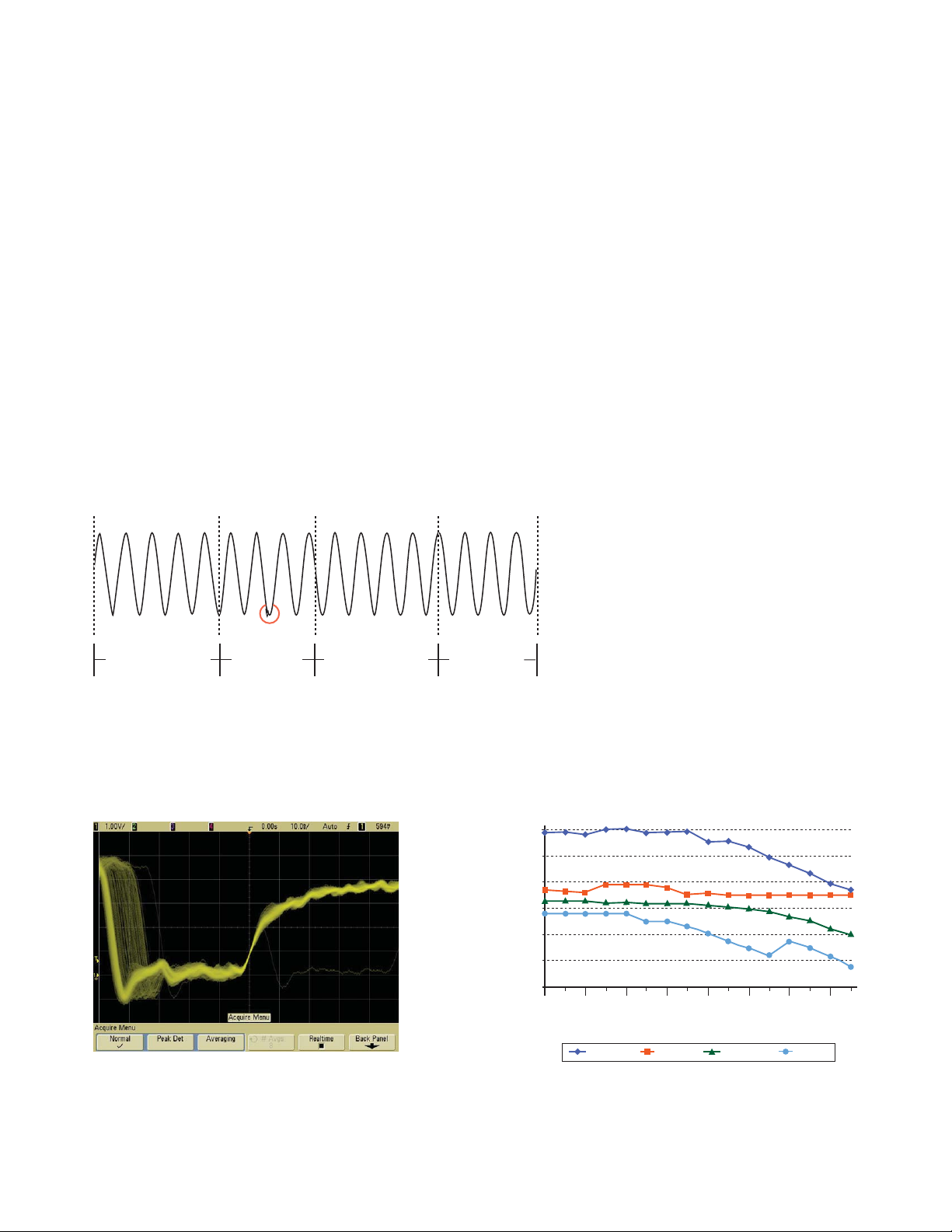
Figure 5. 256 levels of display intensity gradation
show characteristics of jitter, noise, and signal
anomalies.
Figure 6. Comparison of waveform update rates using each scope’s
default real-time acquisition mode.
Figure 4. Slow update rate means long dead time when anomalies may be
missed. With 100,000 wvfms/sec update rate, dead time is minimized.
Acquisition time Dead time Acquisition time Dead time
Update Rate (Waveforms/Sec)
100000
10000
1000
100
10
0.1
1
1 ns/div
5 ns/div
20 ns/div
MSO6000
100 ns/div
Time base
TDS3000 WaveSurfer TDS5000
500 ns/div
2 µs/div
10 µs/div
50 µs/div
Page 7
7
Full-scale connectivity
Standard USB, Ethernet/LAN and
GPIB interfaces – choose the interface
you want to use
The 6000 Series scopes come
with standard USB 2.0 USBTMC
device, 10/100 Mbps LAN and
GPIB interfaces on the rear panel
and USB 1.1 host interfaces on
the front and rear panels.
• USB offers the quickest and
easiest connection scheme –
it’s perfect for benchtop use
and systems connection.
• LAN offers high-speed
connectivity over longer
distances and allows sharing
of instruments among
multiple PCs.
• GPIB has many years of proven
reliability for instrument
communication – a good choice
for use in existing GPIB-based
test systems.
Front-panel USB port
A built-in front-panel USB port
makes it easy for you to store
waveform data, screen images,
and scope setups to a USB
flash drive. You can store your
waveform images as BMP or PNG
files and your waveform data as
CSV, ASCII XY pair and binary
format files for easy import into
other PC applications. If you
share your lab equipment with
others, you can save your
measurement setups and traces
to your own USB flash drive,
making it simple to save and share
your every-day setups as well as
your advanced configurations.
Built-in XGA video output
allows you to connect to a large
external monitor or project your
screen image to a large wall screen
in classroom environments.
Free IntuiLink Data Capture software
simplifies PC connectivity
When you need to transfer images
and waveform data to your PC,
IntuiLink Data Capture lets you
focus more time on design issues
rather than on programming.
With the click of a button on the
Data Capture’s dialog box, you
can download data or transfer
a snapshot of an oscilloscope
bitmap screen directly to your
PC, or save the image as a bitmap
file. For more information on
IntuiLink Data Capture, visit
www.agilent.com/find/intuilink.
IVI-COM driver
For a higher-level of instrument
control, use the IVI-COM driver
for the 6000 Series in your
application. Download the
IVI-COM driver for 6000
Series free from the Agilent
Developer’s Network at
www.agilent.com/find/adn.
Logic analyzer and oscilloscope
correlation
Easily make time-correlated
measurements between an
Agilent 1680, 1690 or 16900
Series logic analyzer and a
6000 Series oscilloscope. The
time-correlated logic analyzer
and 6000 Series oscilloscope
waveforms are integrated into a
single logic analyzer waveform
display for easy viewing and
analysis. You can also trigger
the 6000 Series oscilloscope
from the logic analyzer (or vice
versa), automatically de-skew
the waveforms and maintain
marker tracking between the
two instruments.
Figure 7. A built-in USB port makes it
easy to save and share your work and
update your system software quickly.
Figure 8. Agilent 6000 Series with an
external monitor attached.
Figure 9. Make time-correlated
measurements between an Agilent logic
analyzer and 6000 Series oscilloscope.
Page 8
8
Powerful triggering
Full-width pattern triggering
With mixed analog and digital
designs, sometimes it’s hard to
trace an anomaly back to its root
cause unless you can trigger on it
and correlate it with other signals.
With the 6000 Series scopes,
triggering is no longer a hassle.
They come with flexible triggering
capabilities across all channels so
you can easily isolate and analyze
complex signals and interactions
common in your mixed analog
and digital designs. Trigger on
any combination of events across
all 4 scope and 16 logic channels.
Serial bus triggering
Agilent’s 6000 Series scopes
also allow you to trigger on the
industry’s most popular serial
bus standards. Don’t spend
your time sorting through
communication frames to find
the one of interest. Let Agilent
set up a serial bus trigger to sift
through the frames for you.
• I2C (Inter-Integrated Circuit): The
full range of I2C triggering
includes start or stop condition,
missing acknowledge, restart,
EEPROM data read, address
and/or data frame, or
10-bit write.
• SPI (Serial Peripheral Interface):
SPI triggering lets you trigger
on user-definable framing,
number of bits per frame, as
well as particular data patterns.
• CAN (Controller Area Network):
CAN triggering synchronizes
to the start of a CAN frame
on any CAN high or CAN low
signal. The N5424A option lets
you trigger on CAN message
IDs, data, error frame, or
overload frame as well as
decode CAN messages.
• LIN (Local Interconnect Network):
Trigger on LIN sync break at
the beginning of a message
frame. The N5424A option lets
you trigger on frame ID as well
as decode LIN messages.
• USB (Universal Serial Bus):
USB is quickly becoming the
connection of choice for PC
peripherals. Make your testing
easy with start-of-packet
(SOP), end-of-packet (EOP),
reset complete (RC), enter
suspend, or exit suspend modes.
Instead of spending extra time
using conventional edge triggering
to capture and trace long streams
of serial bus data, let Agilent’s
serial bus triggering help you save
time by automatically finding the
right pattern from long streams of
serial data within your embedded
systems design.
Analog HDTV/EDTV triggering
Capturing and analyzing baseband
high-definition TV waveforms with
a scope has never been easier.
The 6000 Series supports analog
HDTV/EDTV triggering for
emerging standards like 1080i,
1080p, 720p and 480p as well as
standard video triggering on any
line within a field, all lines, all
fields, odd or even fields for
NTSC, SECAM, PAL and PAL-M
video signals.
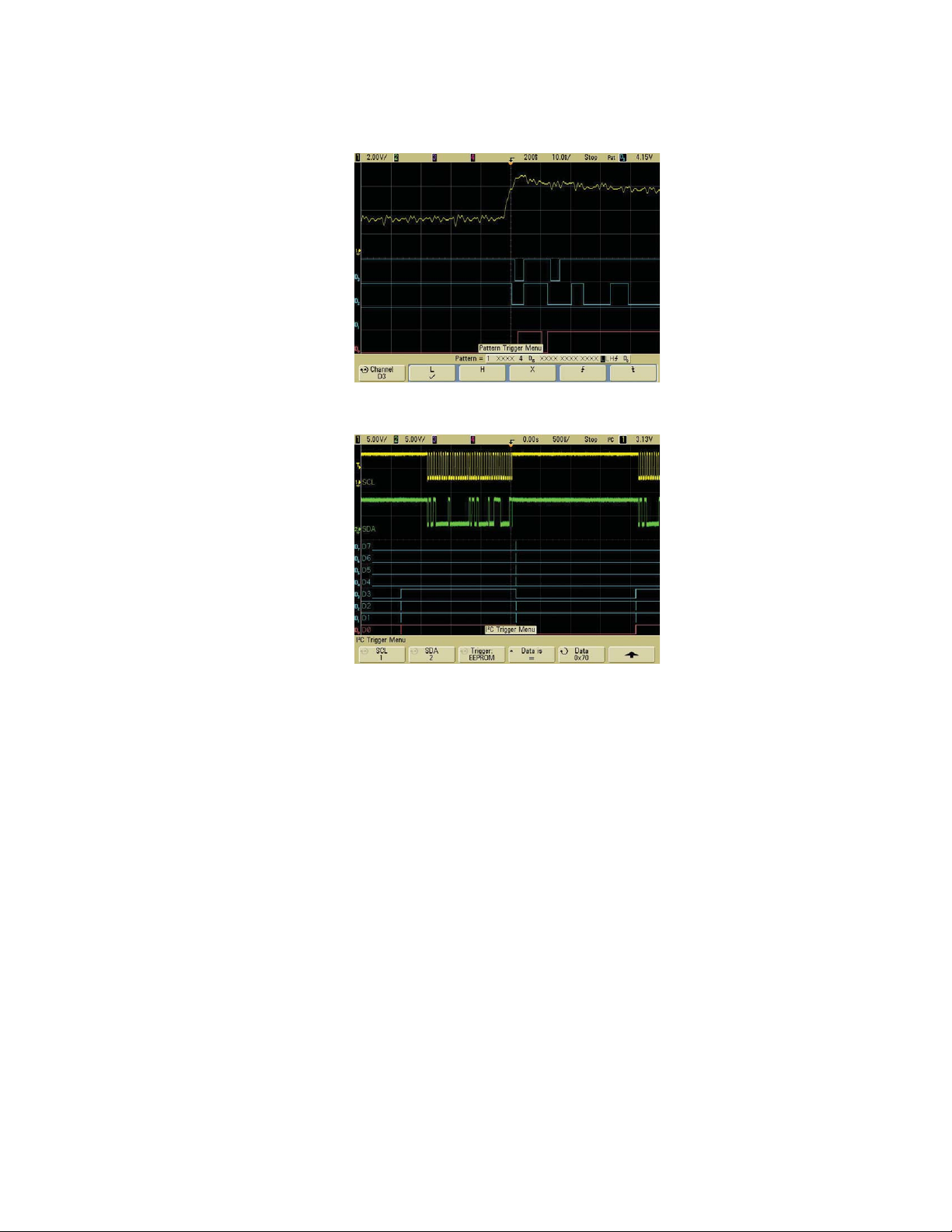
Figure 10. MSOs provide
advanced pattern triggering
across all scope AND logic
channels for quick isolation
of critical events.
Figure 11. Trigger on address
and/or data patterns within
an I
2
C frame.
Page 9
9
Other standard features
• Built-in help at your fingertips
An innovative built-in help
system in six different
languages (English, Japanese,
simplified Chinese, German,
French and Russian) gives you
quick access to the help you
need. If you have a question
about a particular feature,
simply press and hold the
corresponding front-panel key
for a few seconds, and a help
screen pops up to explain its
function. You’ll no longer have
to look for the manual when
you need assistance setting up
scope functions or making
complex measurements.
• Deep memory transfer over the bus
Transfer all of your data over
the bus, even when using deep
memory. Typically it takes less
than 5 seconds to transfer
4 MB of data over USB.
• Easy software upgrades The
system software is stored
in Flash ROM that can be
upgraded easily from the
scope’s built-in USB port.
For a free copy of the system
software and the IntuiLink
Data Capture software, visit
the 6000 Series Web site at
www.agilent.com/find/
MSO6000sw.
• AutoProbe interface, featured
on 300 MHz - 1 GHz models,
automatically sets probe
attenuation factors and provides
power for selected Infiniium
active probes supporting the
award-winning 1130A 1.5 GHz
InfiniiMax differential active
probe and 1156A 1.5 GHz
single-ended active probe. The
100 MHz 6000 Series offers
auto probe sense only.
• Waveform math with FFTs
Analysis functions include
subtract, multiply, integrate,
and differentiate, as well as
FFT (fast Fourier transforms).
• 250-ps peak detect on the
500 MHz/1 GHz models, 500-ps
peak detect on the 300 MHz
models and 1-ns peak detect
on the 100 MHz models means
you won’t have to worry about
missing narrow glitches.
• Autoscale lets you quickly
display any active signals,
automatically setting the
vertical, horizontal and trigger
controls for the best display.
• Easy printer connectivity Use the
standard USB host port on the
rear panel to easily connect
HP Deskjet, Officejet and HP
PCL 3.0 compatible printers.
• Built-in 5-digit hardware counter
measures frequency up to the
bandwidth of the scope (max
1 GHz). The counter resolution
can be increased to 8 digit with
an external 10 MHz reference.
• Built-in 10 MHz reference in/out
port lets you synchronize
multiple measurement
instruments in a system or get
higher accuracy time base using
a high accuracy external clock.
• Trig Out port on the rear panel
provides an easy way to
synchronize your scope to other
instruments. Use the scope’s
Trig Out port to connect your
scope to a frequency counter
for more accurate frequency
measurements or cross trigger
other instruments.
• High resolution mode offers
up to 12 bits of resolution
in real-time (single-shot)
modes, reducing noise. This
is accomplished by serially
filtering sequential data points
and mapping the filtered results
to the display when operating
at slow time base ranges.
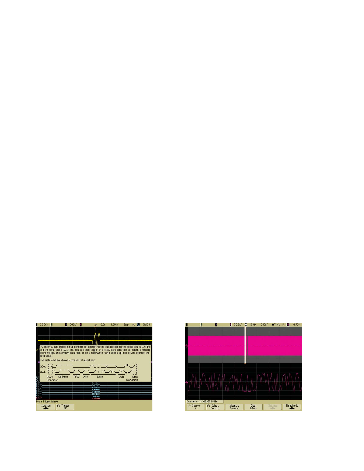
Figure 12. Press and hold any key for built-in Help,
such as this description of the I
2
C bus triggering.
Figure 13. Built-in hardware counter allows for
making 8-digit frequency measurement using an
external 10 MHz reference input.
Page 10

10
Agilent 6000 Series oscilloscopes: The right combination of features
and performance to bring your toughest problems into focus.
MegaZoom III deep memory helps you determine
how your signals are impacting each other. With
shallow memory scopes, you have to choose
whether you look at a slow analog signal or fast
digital content. With up to 8 Mpts deep memory,
you don’t have to choose – capture all of your data
at once.
Revolutionary high-definition color display with
XGA resolution and 256 levels of intensity reveals
subtle details that most scopes won’t show you.
Built-in USB port makes it easy to save your work
and update your system software quickly.
Intensity knob allows you to see the right level of
waveform detail, just like an analog scope.
Free IntuiLink Data Capture PC software makes
transferring waveform data or screen image to a
PC fast and easy.
Built-in 10-MHz reference in/out port lets you synchronize
multiple measurement instruments in a system.
Standard USB, LAN and GPIB ports
provide PC and printer connectivity.
An XGA video output port allows you
to connect to a large external monitor.
Rear panel inputs/outputs
Trig Out port provides an easy way to synchronize your
scope to other instruments.
Page 11

11
Quickly pan and zoom for analysis with
MegaZoom III’s instant response and
optimum resolution.
QuickMeas shows up to four automated
measurements with the push of a button.
QuickPrint automatically prints your screen or
saves screen images to a connected USB storage
device with automated file names.
Standard serial triggering includes CAN, I2C, LIN,
SPI, and USB.
Standard analog HDTV/EDTV triggering supports
triggering on 1080i, 1080p, 720p, 480p HDTV/EDTV
standards.
AutoProbe interface automatically configures the
attenuation ratio of the probe and provides probe
power for Agilent’s active probes (available on
300 MHz - 1 GHz models only).
Built-in help in six languages. Simply press and
hold the front-panel key of interest for a few
seconds, and a help screen pops up to explain
its function.
Maximum sample rate and resolution is achieved
on every measurement. The scope automatically
adjusts memory depth as you use it, so you get
maximum sample rate and resolution on every
measurement. You don’t even have to think about it.
2 or 4 scope and 16 logic channel MSOs allow
you to view and trigger on up to 20 time-aligned
signals on your scope screen.
Built-in storage compartment allows you to
store probes and power cord for easy access
and transportation.
Autoscale lets you quickly display any active
signals, automatically setting the vertical,
horizontal and trigger controls for the best display,
while optimizing memory.
Dedicated front-panel controls make it easy to
access the most common scope controls, including
vertical and horizontal scaling.
Page 12

12
Probes
To get the most out of your scope,
you need the right probes and
accessories for your particular
application. That's why Agilent
Technologies offers a complete
family of innovative passive and
Selection guide
10073C (shipped
10074C (shipped with 6000 Series
with 6000 Series 300 MHz - 1 GHz 10076A N2771A
Agilent passive probes 10070C 100 MHz models) models) high-voltage probe high-voltage probe
Probe bandwidth 20 MHz 150 MHz 500 MHz 250 MHz 50 MHz
Probe rise time (calculated) <17.5 ns <2.33 ns <700 ps <1.4 ns <7 ns
Attenuation ratio 1:1 10:1 10:1 100:1 1000:1
Input resistance (when 1 MΩ 10 MΩ 2.2 MΩ 66.7 MΩ 100 MΩ
terminated into 1 MΩ)
Input capacitance Approx. 70 pF Approx. 15 pF Approx. 12 pF Approx. 3 pF Approx. 1 pF
Maximum input 400 Vpk CAT I 500 Vpk CAT I 500 Vpk CAT I 4000 Vpk 15 kV dc, 10 kVrms,
(dc+peak ac) (mains isolated) (mains isolated) (mains isolated) 30 kV dc + peak ac
400 Vpk CAT II 400 Vpk CAT II 400 Vpk CAT II
(post receptacle (post receptacle (post receptacle
mains) mains) mains)
Compensation range None 9-17 pF 6-15 pF 6-20 pF 7-25 pF
Probe sense No Yes Yes Yes No
Current probes Description
1146A 100 kHz current probe, ac/dc
N2774A 50 MHz current probe, ac/dc
N2775A Power supply for N2774A
1147A 50 MHz current probe, ac/dc with AutoProbe interface
Active single-ended probes Description
1144A 800 MHz active probe
1145A 2-channel 750 MHz active probe .
1142A Power supply for 1144A/1145A
1156A 1.5 GHz active probe with AutoProbe interface
Active differential probes Description
N2772A 20 MHz differential probe
N2773A Probe power supply for N2772A
1130A 1.5 GHz InfiniiMax differential probe amplifier with AutoProbe interface (Order one or
more InfiniiMax probe heads or connectivity kits per amplifier.)
Note:
These Infiniium active probes are not supported by 6000 Series 300 MHz - 1 GHz models – 1152A, 1153A, 1154A, 1155A, 1159A, 1168A, and 1169A. The 6000 Series 100 MHz
models do not support any Agilent Infiniium active probes with AutoProbe interface.
active probes for the 6000 Series
scopes to get your job done easily.
For more comprehensive
information, refer to the Agilent
6000 Series Oscilloscopes Probes
and Accessories Data Sheet
(Agilent publication number
5968-8153EN/ENUS). You can get
a copy by visiting our Web site at:
www.agilent.com/find/MSO6000.
Page 13

13
Applications
N5406A FPGA dynamic probe for
6000 Series MSO
The N5406A FPGA dynamic
probe for the 6000 Series MSO
provides the most effective
solution for validating and
debugging embedded designs
incorporating Xilinx FPGAs. This
innovative solution enables you
to:
• View internal FPGA activity
correlated to external analog
events – With the FPGA
dynamic probe, the 6000 Series
MSO’s 16 digital channels can
be used to access hundreds of
internal signals, unlocking
visibility into your design that
you never had before.
• Make multiple measurements in
seconds – Moving probe points
internal to an FPGA used to
require time consuming
recompiles. Now, in less than a
second you can easily measure
a different set of internal
signals without design changes.
By not changing the design,
FPGA timing stays constant
when you select new sets of
internal signals for probing.
Figure 14. Debug and validate your FPGA designs faster and
more effectively with FPGA dynamic probe and Agilent MSO.
• Leverage the work you did in your
design environment – The FPGA
dynamic probe automatically
maps internal signal names
from your FPGA design tool to
the MSO’s digital channel labels.
This provides easy signal
identification and eliminates
unintentional mistakes while
saving hours of time.
For more information on the
N5406A FPGA dynamic probe,
see the FPGA Dynamic Probe
for Mixed-Signal Oscilloscopes
data sheet (Agilent publication
number 5989-1848EN).
E2690B oscilloscope tools
The E2690B oscilloscope’s tools,
licensed by Agilent Technologies
from Amherst Systems Associates
(ASA), are the most powerful
suites of analysis, debug,
collaboration and automation
tools for Agilent real-time
oscilloscopes. The E2690B
oscilloscope tools make it easy
for in-depth analysis of the
captured signals.
This software works with the
6000 Series 300 MHz - 1 GHz
models. For more information on
the E2690B oscilloscope tools, see
the E2690B Oscilloscope Tools
data sheet (Agilent publication
number 5989-3525EN).
89601A vector signal
analysis software
Expand the measurement
capability of your 6000 Series
scope with the 89601A vector
signal analysis software. This
advanced DSP based software
takes the digitized signal data
provided by the scope and
provides FFT based spectrum
analysis and wide bandwidth
digital modulation analysis. Use
these capabilities to demodulate
wireless communication signals
like WCDMA and cdma2000, and
wireless networking signals like
802.11 WiFi and 802.16 WiMax.
Take advantage of the super wide
bandwidth of your scope to
capture and evaluate radar signals.
Figure 15. The E2690B oscilloscope tools make it easy
for in-depth analysis of the captured signals.
Page 14

14
Applications (continued)
N5423A I2C/SPI serial
decode option
The N5423A serial decode
option for I2C and SPI bus
displays responsive, time-aligned
on-screen decode of I2C and SPI
serial buses. Agilent I2C and SPI
serial bus decode software for
6000 Series scopes provides the
fastest throughput solution for
triggering on and analyzing I2C or
SPI serial buses implemented in
a wide variety of computer and
embedded designs.
You can easily isolate serial
packets to find sources of errors
due to hardware or software
related problems. The I2C/SPI
serial decode option lets you
effectively troubleshoot an
embedded system capturing and
decoding I2C or SPI buses,
correlating them with other
signals in the design such as
digital control signals using a
mixed-signal oscilloscope (MSO),
and analog signals interfacing
with the real world.
This software works with the
6000 Series oscilloscopes 4-channel
DSOs or 4+16-channel MSOs only
and decodes any combination of
scope or logic channels.
N2918A oscilloscope evaluation
kit for 6000 Series oscilloscope
The N2918A scope evaluation kit
for 6000 Series MSOs provides
signals to help you experience
the power of Agilent 6000 Series
MSOs. The kit includes a variety
of signals that demonstrate
MegaZoom III technology with
its fast deep memory, superior
waveform update rate, high
definition display and mixed
analog, digital and serial signals
debugging. Using this scope
evaluation kit along with the
easy-to-follow user’s guide, you
can quickly become familiar with
how to effectively use an MSO.
N5424A CAN/LIN automotive
triggering and decode option
The most common serial buses
utilized in today’s automotive
applications are CAN and LIN. To
find and fix signal integrity
problems in the naturally harsh
environment in automobiles,
automotive design engineers need
scopes that can trigger on and
decode serially transmitted data
based on these protocols. Agilent
N5424A CAN/LIN automotive
triggering and decode option for
the 6000 series oscilloscopes not
Figure 16. On-screen serial decode of an I2C packet.
Figure 17. N2918A helps you experience the power of
Agilent 6000 MSO.
only provide triggering on complex
serial signals, but also provides
unique hardware-accelerated
decode capabilities. Hardwareaccelerated decode enables
automotive engineers to capture
random and infrequent events
with color-coded serial bus trace
to quickly identify error frames.
This software works with the
6000 Series oscilloscopes
4-channel DSOs or 4+16-channel
MSOs only.
For more information about this
option, check out the Serial Bus
Triggering and Decode option
data sheet (Agilent publication
number 5989-5126EN) or
application note #1576.
Page 15

15
Performance characteristics
Acquisition: scope channels
Sample rate MSO/DSO601xA/603xA: 2 GSa/sec each channel
MSO/DSO605xA/610xA: 4 GSa/sec half channel*, 2 GSa/sec each channel
Equivalent-time sample rate: 400 GSa/s (when real-time mode is turned off)
Standard memory depth With logic channels turned off,
1 Mpts half channel*, 500 kpts each channel
With logic channels turned on,
625 kpts half channel*, 312 kpts each channel
Optional memory depth With logic channels turned off,
Option 2ML or 2MH – 2 Mpts half channel*, 1 Mpts each channel
Option 8ML or 8MH – 8 Mpts half channel*, 4 Mpts each channel
With logic channels turned on,
Option 2ML or 2MH – 1.25 Mpts half channel*, 625 kpts each channel
Option 8ML or 8MH – 5 Mpts half channel*, 2.5 Mpts each channel
Vertical resolution 8 bits
Peak detection MSO/DSO601xA: 1-ns peak detect
MSO/DSO603xA: 500-ps peak detect
MSO/DSO605xA/610xA: 250-ps peak detect
Averaging Selectable from 2, 4, 8, 16, 32, 64 … to 65536
High resolution mode Average mode with avg = 1
12 bits of resolution when ≥10 µs/div @ 4 GSa/s or ≥20 µs/div @ 2 GSa/s
Filter Sinx/x interpolation (single shot BW = sample rate/4 or bandwidth of scope,
whichever is less) with vectors on and in real-time mode
Acquisition: logic channels (MSO6000A or MSO-upgraded DSO6000A only)
Sample rate 2 GSa/sec one pod, 1 GSa/sec each pod
Maximum input frequency 250 MHz
Standard memory depth With scope channels turned off,
1 Mpts one pod, 500 kpts each pod
With scope channels turned on,
312 kpts one pod, 156 kpts each pod
Optional memory depth With scope channels turned off,
Option 2ML or 2MH – 2 Mpts one pod, 1 Mpts each pod
Option 8ML or 8MH – 8 Mpts one pod, 4 Mpts each pod
With scope channels turned on,
Option 2ML or 2MH – 625 kpts one pod, 312 kpts each pod
Option 8ML or 8MH – 2.5 Mpts one pod, 1.25 Mpts each pod
Vertical resolution 1 bit
Glitch detection 2 ns (min pulse width)
* Half channel is when only one of channel 1 or 2 is turned on, or only channel 3 or 4 is turned on.
Page 16

16
Performance characteristics (continued)
Vertical system: scope channels
Scope channels MSO/DSO6xx2A: Ch 1 and 2 simultaneous acquisition
MSO/DSO6xx4A: Ch 1, 2, 3 and 4 simultaneous acquisition
Bandwidth (–3dB)* MSO/DSO601xA: DC to 100 MHz
MSO/DSO603xA: DC to 300 MHz
MSO/DSO605xA: DC to 500 MHz
MSO/DSO610xA: DC to 1 GHz
AC coupled MSO/DSO601xA: 3.5 Hz to 100 MHz
MSO/DSO603xA: 3.5 Hz to 300 MHz
MSO/DSO605xA: 3.5 Hz to 500 MHz
MSO/DSO610xA: 3.5 Hz to 1 GHz
Calculated rise time (=0.35/bandwidth) MSO/DSO601xA: 3.5 nsec
MSO/DSO603xA: 1.17 nsec
MSO/DSO605xA: 700 psec
MSO/DSO610xA: 350 psec
Single-shot bandwidth MSO/DSO601xA: 100 MHz
MSO/DSO603xA: 300 MHz
MSO/DSO605xA: 500 MHz
MSO/DSO610xA: 1 GHz (in half-channel mode)
Range
1
MSO/DSO601xA: 1 mV/div to 5 V/div (1 MΩ)
MSO/DSO603xA and MSO/DSO605xA: 2 mV/div to 5 V/div (1 MΩ or 50 Ω)
MSO/DSO610xA: 2 mV/div to 5 V/div (1 MΩ), 2 mV/div to 1 V/div (50 Ω)
Maximum input CAT I 300 Vrms, 400 Vpk; transient overvoltage 1.6 kVpk
CAT II 100 Vrms, 400 Vpk
With 10073C or 10074C 10:1 probe: CAT I 500 Vpk, CAT II 400 Vpk
Offset range ±5 V on ranges <10 mV/div; ±20 V on ranges 10 mV/div to 200 mV/div;
±75 V on ranges >200 mV/div
Dynamic range ±8 div
Input impedance MSO/DSO601xA: 1 MΩ ± 1% || 11 pF
MSO/DSO603xA/605xA/610xA: 1 MΩ ± 1% || 14 pF or 50 Ω ± 1.5%, selectable
Coupling AC, DC
BW limit MSO/DSO601xA: 20 MHz selectable
MSO/DSO603xA/605xA/610xA: 25 MHz selectable
Channel-to-channel isolation DC to max bandwidth >40 dB
Standard probes MSO/DSO601xA: 10:1 10074C shipped standard for each scope channel
MSO/DSO603xA/605xA/610xA: 10:1 10073C shipped standard for each scope channel
Probe ID MSO/DSO601xA: Auto probe sense
MSO/DSO603xA/605xA/610xA: Auto probe sense and AutoProbe interface
Agilent- and Tektronix-compatible passive probe sense
ESD tolerance ±2 kV
* Denotes warranted specifications, all others are typical. Specifications are valid after a 30-minute warm-up period and ±10 °C from firmware calibration temperature.
1 1 mV/div is a magnification of 2 mV/div setting for 100 MHz models and 2 mV/div is a magnification of 4 mV/div setting for 300 MHz - 1 GHz models. For vertical accuracy
calculations, use full scale of 16 mV for 1 mV/div sensitivity setting and 32 mV for 2 mV/div sensitivity setting.
Page 17

17
Performance characteristics (continued)
Vertical system: scope channels (continued)
Noise peak-to-peak MSO/DSO601xA: 3% full scale or 2 mV, whichever is greater
MSO/DSO603xA: 3% full scale or 3 mV, whichever is greater
MSO/DSO605xA: 3% full scale or 3.6 mV, whichever is greater
MSO/DSO610xA: 3% full scale or 4 mV, whichever is greater
DC vertical gain accuracy*
1
±2.0% full scale
DC vertical offset accuracy ≤200 mV/div: ±0.1 div ±2.0 mV ±0.5% offset value;
>200 mV/div: ±0.1 div ±2.0 mV ±1.5% offset value
Single cursor accuracy
1
±{DC vertical gain accuracy + DC vertical offset accuracy + 0.2% full scale (~1/2 LSB)}
Example: for 50 mV signal, scope set to 10 mV/div (80 mV full scale), 5 mV offset,
accuracy = ±{2.0% (80 mV) + 0.1 (10 mV) + 2.0 mV + 0.5% (5 mV) + 0.2%(80 mV)} = ± 4.785 mV
Dual cursor accuracy*
1
±{DC vertical gain accuracy + 0.4% full scale (~1 LSB)}
Example: for 50 mV signal, scope set to 10 mV/div (80 mV full scale), 5 mV offset,
accuracy = ±{2.0% (80 mV) + 0.4% (80 mV)} = ±1.92 mV
* Denotes warranted specifications, all others are typical. Specifications are valid after a 30-minute warm-up period and ±10 °C from firmware calibration temperature.
1 1 mV/div is a magnification of 2 mV/div setting for 100 MHz models and 2 mV/div is a magnification of 4 mV/div setting for 300 MHz - 1 GHz models. For vertical accuracy
calculations, use full scale of 16 mV for 1 mV/div sensitivity setting and 32 mV for 2 mV/div sensitivity setting.
Vertical system: logic channels (MSO6000A or MSO-upgraded DSO6000A only)
Number of channels 16 logic timing channels – labeled D15 - D0
Threshold groupings Pod 1: D7 - D0
Pod 2: D15 - D8
Threshold selections TTL, CMOS, ECL and user-definable (selectable by pod)
User-defined threshold range ±8.0 V in 10 mV increments
Maximum input voltage ±40 V peak CAT I; transient overvoltage 800 Vpk
Threshold accuracy* ±(100 mV + 3% of threshold setting)
Input dynamic range ±10 V about threshold
Minimum input voltage swing 500 mV peak-to-peak
Input capacitance ~8 pF
Input resistance 100 kΩ ±2% at probe tip
Channel-to-channel skew 2 ns typical, 3 ns maximum
* Denotes warranted specifications, all others are typical. Specifications are valid after a 30-minute warm-up period and ±10 °C from firmware calibration temperature.
Page 18

18
Performance characteristics (continued)
Horizontal
Range MSO/DSO601xA: 5 nsec/div to 50 sec/div
MSO/DSO603xA: 2 nsec/div to 50 sec/div
MSO/DSO605xA: 1 nsec/div to 50 sec/div
MSO/DSO610xA: 500 psec/div to 50 sec/div
Resolution 2.5 psec
Time base accuracy 15 ppm (±0.0015%)
Vernier 1-2-5 increments when off, ~25 minor increments between major settings when on
Delay range Pre-trigger (negative delay): Greater of 1 screen width or 1 ms (with 8 Mpts memory option)
Greater of 1 screen width or 250 µs (with 2 Mpts memory option)
Greater of 1 screen width or 125 µs (with standard memory)
Post-trigger (positive delay): 1 s - 500 seconds
Analog delta-t accuracy Same channel: ±0.0015% reading ±0.1% screen width ±20 ps
Channel-to-channel: ±0.0015% reading ±0.1% screen width ±40 ps
Same channel example (MSO/DSO605xA):
For signal with pulse width of 10 µs, scope set to 5 µs/div (50 µs screen width),
delta-t accuracy = ±{0.0015% (10 µs) + 0.1% (50 µs) + 20 ps} = 50.17 ns
Logic delta-t accuracy Same channel: ±0.005% reading ±0.1% screen width ±(1 logic sample period, 1 ns)
Channel-to-channel:
±0.005% reading ±0.1% screen width ±(1 logic sample period) ±chan-to-chan skew
Same channel example:
For signal with pulse width of 10 µs, scope set to 5 µs/div (50 µs screen width),
delta-t accuracy = ±{0.005% (10 µs) + 0.1% (50 µs) + 1 ns} = 51.5 ns
Modes Main, delayed, roll, XY
XY Bandwidth: Max bandwidth
Phase error @ 1 MHz: <0.5 degrees
Z Blanking: 1.4 V blanks trace (use external trigger on MSO/DSO6xx2A,
channel 4 on MSO/DSO6xx4A)
Reference positions Left, center, right
Trigger system
Sources MSO6xx2A: Ch 1, 2, line, ext, D15 - D0
DSO6xx2A: Ch 1, 2, line, ext
MSO6xx4A: Ch 1, 2, 3, 4, line, ext, D15 - D0
DSO6xx4A: Ch 1, 2, 3, 4, line, ext
Modes Auto, Normal (triggered), single
Holdoff time ~60 ns to 10 seconds
Trigger jitter 15 ps rms
Page 19

19
Performance characteristics (continued)
Trigger system (continued)
Selections Edge, pulse width, pattern, TV, duration, sequence, CAN, LIN, USB, I2C, SPI, Nth edge burst
Edge Trigger on a rising, falling, alternating or either edge of any source
Pattern Trigger at the beginning of a pattern of high, low, and don’t care levels and/or a rising or
falling edge established across any of the analog and digital channels, but only after a
pattern has stabilized for a minimum of 2 nsec.
The scope channel’s high or low level is defined by that channel’s trigger level. The logic
channel’s trigger level is defined by the threshold for the pod, 0 - 7 or 8 - 15.
Pulse width Trigger when a positive- or negative-going pulse is less than, greater than, or within a
specified range on any of the source channels.
Minimum pulse width setting: 5 ns (MSO/DSO601xA/603xA scope channels)
2 ns (MSO/DSO605xA/610xA scope channels)
2 ns (logic channels on MSO6000A or
MSO-upgraded DSO6000A)
Maximum pulse width setting: 10 s
TV Trigger using any scope channel on most analog progressive and interlaced video standards
including HDTV/EDTV, NTSC, PAL, PAL-M or SECAM broadcast standards. Select either
positive or negative sync pulse polarity. Modes supported include Field 1, Field 2, all fields,
all lines, or any line within a field. TV trigger sensitivity: 0.5 division of sync signal. Trigger
holdoff time can be adjusted in half field increments.
Sequence Arm on event A, trigger on event B, with option to reset on event C or time delay.
CAN Trigger on CAN (Controller Area Network) version 2.0A and 2.0B signals. Trigger on the start
of frame (SOF) bit (standard). N5424A option supports triggering on remote frame ID (RTR),
data frame ID (~RTR), remote or data frame ID, data frame ID and data, error frame, all errors,
acknowledge error and overload frame.
LIN Trigger on LIN (Local Interconnect Network) sync break at beginning of message frame
(standard). N5424A option supports triggering on frame ID.
USB Trigger on USB (Universal Serial Bus) start of packet, end of packet, reset complete, enter
suspend, or exit suspend on the differential USB data lines. USB low speed and full speed
are supported.
I
2
C Trigger on I2C (Inter-IC bus) serial protocol at a start/stop condition or user defined frame
with address and/or data values. Also trigger on missing acknowledge, address with no acq,
restart, EEPROM read, and 10-bit write.
SPI Trigger on SPI (Serial Protocol Interface) data pattern during a specific framing period.
Supports positive and negative Chip Select framing as well as clock Idle framing and
user-specified number of bits per frame.
Duration Trigger on a multi-channel pattern whose time duration is less than a value, greater than a
value, greater than a time value with a timeout, or inside or outside of a set of time values.
Minimum duration setting: 2 ns
Maximum duration setting: 10 s
Nth edge burst Trigger on the Nth edge of a burst that occurs after an idle time that you specify. Max edge
count: 65,536.
Autoscale Finds and displays all active scope and logic (for MSO6000A series MSO) channels, sets edge
trigger mode on highest-numbered channel, sets vertical sensitivity on scope channels and
thresholds on logic channels, time base to display ~1.8 periods. Requires minimum voltage
>10 mVpp, 0.5% duty cycle and minimum frequency >50 Hz.
Page 20

20
Performance characteristics (continued)
Scope channel triggering
Range (internal) ±6 div from center screen
Sensitivity* <10 mV/div: greater of 1 div or 5 mV; ≥10 mV/div: 0.6 div
Coupling AC (~3.5 Hz on MSO/DSO601xA, ~10 Hz on MSO/DSO603xA/605xA/610xA),
DC, noise reject, HF reject and LF reject (~50 kHz)
Logic (D15 - D0) channel triggering (MSO6000A or MSO-upgraded DSO6000A only)
Threshold range (user defined) ±8.0 V in 10 mV increments
Threshold accuracy* ±(100 mV + 3% of threshold setting)
Predefined thresholds TTL = 1.4 V, CMOS = 2.5 V, ECL = -1.3 V
External (EXT) triggering MSO/DSO6xx2A (2-/2+16-ch models) MSO/DSO6xx4A (4-/4+16-ch models)
Input impedance MSO/DSO6012A: 1 MΩ ± 3% || 11 pF or 50 Ω MSO/DSO6014A: 1.015 kΩ ±5%
MSO/DSO6032A/6052A/6102A: MSO/DSO6034A/6054A/6104A:
1 MΩ ± 3% || 14 pF or 50 Ω 2.14 kΩ ±5%
Maximum input CAT I 300 Vrms, 400 Vpk, CAT II 100 Vrms, 400 Vpk ±15 V
With 10073C 10:1 probe: CAT I 500 Vpk, CAT II 400 Vpk
5 Vrms with 50-ohm input
Range DC coupling: trigger level ±1 V and ±8 V ±5 V
Sensitivity For ±1 V range setting: DC to 100 MHz, 100 mV; MSO/DSO6014A:
MSO/DSO6032A/6052A/6102A: DC to 100 MHz: 500 mV
>100 MHz to bandwidth of oscilloscope: 200 mV MSO/DSO6034A/6054A/6104A:
For ±8 V range setting: DC to 100 MHz, 250 mV; DC to 500 MHz: 500 mV
MSO/DSO6032A/6052A/6102A:
>100 MHz to bandwidth of oscilloscope: 500 mV
Coupling AC (~3.5 Hz), DC, noise reject, HF reject and LF reject (~50 kHz)
Probe ID MSO/DSO601xA: Auto probe sense
MSO/DSO603xA/605xA/610xA: Auto probe sense and AutoProbe interface
Agilent- and Tektronix-compatible passive probe sense
Display system
Display 6.3-inch (161 mm) diagonal color TFT LCD
Throughput of scope channels Up to 100,000 waveforms/sec in real-time mode
Resolution XGA – 768 vertical by 1024 horizontal points (screen area);
640 vertical by 1000 horizontal points (waveform area)
256 levels of intensity scale
Controls Waveform intensity on front panel. Vectors on/off; infinite persistence on/off,
8 x 10 grid with intensity control
Built-in help system Key-specific help (in English) displayed by pressing and holding key or softkey of interest
Real-time clock Time and date (user adjustable)
* Denotes warranted specifications, all others are typical. Specifications are valid after a 30-minute warm-up period and ±10 °C from firmware calibration temperature.
Page 21

21
Performance characteristics (continued)
Measurement features
Automatic measurements Measurements are continuously updated. Cursors track last selected measurement.
Up to four measurements can be displayed on screen at any one time.
Voltage (scope channels only) Peak-to-peak, maximum, minimum, average, amplitude, top, base, overshoot, preshoot, RMS,
standard deviation (AC RMS)
Time Frequency, period, + width, – width and duty cycle on any channel
Rise time, fall time, X at max Y (time at max volts), X at min Y (time at min volts), delay, and
phase on scope channels only
Counter Built-in 5-digit frequency counter on any channel. Counts up to the scope’s bandwidth (1 GHz
max). The counter resolution can be increased to 8 digits with an external 10 MHz reference.
Threshold definition Variable by percent and absolute value; 10%, 50%, 90% default for time measurements
Cursors Manually or automatically placed readout of Horizontal (X, ∆X, 1/∆X) and Vertical (Y, ∆Y).
Additionally logic or scope channels can be displayed as binary or hex values.
Waveform math One function of 1-2, 1x2, FFT, differentiate, integrate.
Source of FFT, differentiate, integrate: scope channels 1 or 2, 1-2, 1+2, 1x2.
FFT
Points Fixed at 1000 points
Source of FFT Scope channels 1 or 2 (or 3 or 4 on MSO/DSO6xx4A only), 1+2, 1-2, 1*2
Window Rectangular, flattop, hanning
Noise floor –50 to –90 dB depending on averaging
Amplitude Display in dBV, dBm at 50 Ω
Frequency resolution 0.05/time per div
Maximum frequency 50/time per div
Storage
Save/recall (non-volatile) 10 setups and traces can be saved and recalled internally.
Storage type and format USB 1.1 host ports on front and rear panels
Image formats: BMP (8-bit), BMP (24-bit), PNG (24-bit)
Data formats: X and Y (time/voltage) values in CSV format, ASCII XY and binary format
Trace/setup formats: Recalled
I/O
Standard ports USB 2.0 high speed device, two USB 1.1 host ports, 10/100-BaseT LAN, IEEE488.2 GPIB,
XGA video output
Max transfer rate IEEE488.2 GPIB: 500 kbytes/sec
USB (USBTMC-USB488): 3.5 Mbytes/sec
100 Mbps LAN (TCP/IP): 1 Mbytes/sec
Printer compatibility Selected HP Deskjet, Officejet and HP PCL 3.0 compatible printers
Page 22

22
Performance characteristics (continued)
General characteristics
Physical size 35.4 cm wide x 18.8 cm high x 28.2 cm deep (without handle)
39.9 cm wide x 18.8 cm high x 28.2 cm deep (with handle)
Weight Net: 4.9 kgs (10.8 lbs)
Shipping: 9.4 kgs (20.7 lbs)
Probe comp output Frequency ~2 kHz; Amplitude ~5 V
Trigger out When Triggers is selected (delay ~17 ns)
0 to 5 V into high impedance
0 to 2.5 V into 50 Ω
When Source Frequency or Source Frequency/8* is selected
0 to 580 mV into high impedance
0 to 290 mV into 50 Ω
Max frequency output: 350 MHz (in source frequency mode when terminated in 50 Ω)
125 MHz (in source frequency/8 mode when terminated in 50 Ω)
10 MHz ref in/out TTL out, 180 mV to 1 V amplitude with 0 to 2 V offset
Kensington lock Connection on rear panel for security
Power requirements
Line voltage range ~Line 120 W max, 96-144 V/48-440 Hz, 192-288 V/48-66 Hz, automatic selection
Line frequency 50/60 Hz, 100-240 VAC; 440 Hz, 100-132 VAC
Power usage 110 W max
Environmental characteristics
Ambient temperature Operating –10 °C to +55 °C; non-operating –51 °C to +71 °C
Humidity Operating 95% RH at 40 °C for 24 hr; non-operating 90% RH at 65 °C for 24 hr
Altitude Operating to 4,570 m (15,000 ft); non-operating to 15,244 m (50,000 ft)
Vibration Agilent class B1 and MIL-PRF-28800F; class 3 random
Shock Agilent class B1and MIL-PRF-28800F; class 3 random; (operating 30g, 1/2 sine, 11-ms
duration, 3 shocks/axis along major axis, total of 18 shocks)
Pollution degree2 Normally only dry non-conductive pollution occurs.
Occasionally a temporary conductivity caused by condensation must be expected.
Indoor use Rated for indoor use only
Other
Measurement categories CAT I: Mains isolated
CAT II: Line voltage in appliance and to wall outlet
Regulatory information Safety IEC 61010-1:2001 / EN 61010-1:2001
Canada: CSA C22.2 No. 1010.1:1992
UL 61010B-1:2003
Supplementary information The product herewith complies with the requirements of the Low Voltage Directive
73/23/EEC and the EMC Directive 89/336/EEC, and carries the CE-marking accordingly.
The product was tested in a typical configuration with HP/Agilent test systems.
* Source Frequency/8 is supported on 300 MHz - 1 GHz 6000 Series only.
Page 23

23
Ordering information
Model number Description
DSO6012A 100 MHz 2-ch DSO
MSO6012A 100 MHz 2+16-ch MSO
DSO6014A 100 MHz 4-ch DSO
MSO6014A 100 MHz 4+16-ch MSO
DSO6032A 300 MHz 2-ch DSO
MSO6032A 300 MHz 2+16-ch MSO
DSO6034A 300 MHz 4-ch DSO
MSO6034A 300 MHz 4+16-ch MSO
DSO6052A 500 MHz 2-ch DSO
MSO6052A 500 MHz 2+16-ch MSO
DSO6054A 500 MHz 4-ch DSO
MSO6054A 500 MHz 4+16-ch MSO
DSO6102A 1 GHz 2-ch DSO
MSO6102A 1 GHz 2+16-ch MSO
DSO6104A 1 GHz 4-ch DSO
MSO6104A 1 GHz 4+16-ch MSO
Accessories included:
Model number DSO600xA MSO600xA
User’s guide (localized), Service √√
guide, Programmer’s guide
Power cord √√
10:1 divider passive probe √√
per scope channel
Front panel cover √√
Agilent IO libraries suite 14.0 √√
16:2 x 8 input logic probe √
MSO logic cable tray √
Standard 1-year warranty √√
Note:
IntuiLink Data Capture software available free on web at
www.agilent.com/find/intuilink
Page 24

24
Ordering information (continued)
Available options
Option number Description MSO/DSO603xA MSO/DSO605xA MSO/DSO610xA
Option 2ML 2 Mpts memory for √
MSO/DSO601xA/603xA models
Option 8ML 8 Mpts memory for √
MSO/DSO601xA/603xA models
Option 2MH 2 Mpts memory for √√
MSO605xA/610xA models
Option 8MH 8 Mpts memory for √√
MSO605xA/610xA models
N2910A 2 Mpts memory for √
MSO/DSO601xA/603xA models
(after purchase)
N2911A 8 Mpts memory for √
MSO/DSO601xA/603xA models
(after purchase)
N2912A 2 Mpts memory for √√
MSO605xA/610xA models
(after purchase)
N2913A 8 Mpts memory for √√
MSO605xA/610xA models
(after purchase)
N2914A* MSO upgrade kit for √ (for DSOs only)
MSO/DSO601xA/603xA models
N2915A* MSO upgrade kit for √ (for DSOs only) √ (for DSOs only)
DSO605xA/610xA models
* Includes a 54620-68701 logic cable kit, a label and an upgrade license to activate the MSO features
Warranty and calibration options
All models include a standard 1-year warranty.
Option number Description
R-51B-001-3C 1-year return-to-Agilent warranty, extended to 3-years
R-51B-001-5C 1-year return-to-Agilent warranty, extended to 5-years
A6J ANSI Z540-compliant calibration
Page 25

25
Ordering information (continued)
Accessories
Product number Description
1180CZ Testmobile scope cart
N2916A Rackmount kit for 6000 Series scope
N2917A Transit case for 6000 Series scope
N2919A Testmobile bracket for 1180CZ and 6000 Series
Passive probes
Product number Description
10070C 1:1 passive probe with ID
10073C 10:1 500 MHz passive probe with ID (shipped standard with 6000 Series
300 MHz - 1 GHz models)
10074C 10:1 150 MHz passive probe with ID (shipped standard with 6000 Series 100 MHz models)
Fine pitch probing
Product number Description
10072A Fine-pitch probe kit
10075A 0.5 mm, IC clip kit
E2613B 0.5 mm, Wedge probe adapter, 3-signal, qty 2
E2614A 0.5 mm, Wedge probe adapter, 8-signal, qty 1
E2643A 0.5 mm, Wedge probe adapter, 16-signal, qty 1
E2615B 0.65 mm, Wedge probe adapter, 3-signal, qty 2
E2616A 0.65 mm, Wedge probe adapter, 8-signal, qty 1
E2644A 0.65 mm, Wedge probe adapter, 16-signal, qty 1
Current probes
Product number Description
1146A 100 kHz current probe, ac/dc
N2774A 50 MHz current probe, ac/dc
N2775A Power supply for N2774A
1147A 50 MHz current probe, ac/dc with AutoProbe interface
Page 26

26
Ordering information (continued)
High-voltage probes
Product number Description
10076A 100:1, 4 kV, 250 MHz probe with ID
N2771A 1000:1, 15 kV, 50 MHz high-voltage probe
Logic probes
Product number Description
10085-68701 16:16 logic cable and terminator
54620-68701 16:2 x 8 logic input probe assembly (shipped standard with all MSO6000A)
Active single-ended probes
Product number Description
1144A 800 MHz active probe
1145A 2-channel 750 MHz active probe
1142A Power supply for 1144A and 1145A
1156A 1.5 GHz active probe with AutoProbe interface
Active differential probes
Product number Description
N2772A 20 MHz differential probe
N2773A Differential probe power supply for N2772A
1141A 200 MHz differential probe
1142A Probe control and power module for 1141A
1130A 1.5 GHz InfiniiMax differential probe amplifier with AutoProbe interface (Order one or
more InfiniiMax probe heads or connectivity kits per amplifier.)
Cable
Product number Description
10833A GPIB cable, 1 m long
Manual
Option number Description
ABA Printed user’s guide in English
ABJ Printed user’s guide in Japanese
AB2 Printed user’s guide in simplified Chinese
Page 27

27
Ordering information (continued)
Applications
Product number Description
N5406A FPGA dynamic probe for 6000 Series scope (One option listed below must be ordered.)
Option 001 Oscilloscope-locked license
Option 002 PC-locked license
E2690B Oscilloscope tools software (US and Canada)
N5385B Oscilloscope tools software (International)
(One option listed below must be ordered.)
Option 004 Scope advisor for MSO/DSO610xA
Option 005 Scope guide for MSO/DSO603xA/605xA
E2693B 1 year subscription for oscilloscope tools (US and Canada)
E5388B 1 year subscription for oscilloscope tools (International)
(One option listed below must be ordered.)
Option 004 Subscription service for scope advisor
Option 005 Subscription service for scope guide
N5423A (Option LSS) I2C/SPI serial decode option (for 4/4+16 ch models only)
N5424A (Option AMS) CAN/LIN automotive triggering and decode (for 4/4+16 ch models only)
N2918A Oscilloscope evaluation kit for 6000 Series scope
Related Literature
Publication Title Publication Type Publication Number
Agilent Technologies 6000 and 54600 Series Oscilloscope Probes and Accessories Data Sheet 5968-8153EN/EUS
Serial Bus Triggering and Hardware-Accelerated Decode Options for Agilent 6000 Series Data Sheet 5989-5126EN
Oscilloscopes
Agilent Technologies FPGA Dynamic Probe for Mixed-Signal Oscilloscopes Data Sheet 5989-1848EN
E2690B Oscilloscope Tools Data Sheet 5989-3525EN
Improve Your Ability to Capture Elusive Events: Application Note 1551 5989-2002EN
Why Oscilloscope Waveform Update Rates are Important
Debugging Embedded Mixed-Signal Designs Using Mixed Signal Oscilloscopes Application Note 1562 5989-3702EN
Oscilloscope Display Quality Impacts Ability to Uncover Signal Anomalies Application Note 1552 5989-2003EN
Application Note 1553 5989-2004EN
Deep Memory Oscilloscopes: The New Tools of Choice Application Note 1446 5988-9106EN
Evaluating Oscilloscope Vertical Noise Characteristics Application Note 1558 5989-3020EN
Using an Agilent 6000 Series MSO to Debug an Automotive CAN Bus Application Note 1576 5989-5049EN
Ten Things to Consider When Selecting Your Next Oscilloscope Application Note 1490 5989-0552EN
Page 28

www.agilent.com
Agilent Technologies’ Test and Measurement Support, Services, and Assistance
Agilent Technologies aims to maximize the value you receive, while minimizing your risk and
problems. We strive to ensure that you get the test and measurement capabilities you paid
for and obtain the support you need. Our extensive support resources and services can help
you choose the right Agilent products for your applications and apply them successfully.
Every instrument and system we sell has a global warranty. Two concepts underlie Agilent’s
overall support policy: “Our Promise” and “Your Advantage.”
Our Promise
Our Promise means your Agilent test and measurement equipment will meet its advertised
performance and functionality. When you are choosing new equipment, we will help you
with product information, including realistic performance specifications and practical
recommendations from experienced test engineers. When you receive your new Agilent
equipment, we can help verify that it works properly and help with initial product operation.
Your Advantage
Your Advantage means that Agilent offers a wide range of additional expert test and
measurement services, which you can purchase according to your unique technical and
business needs. Solve problems efficiently and gain a competitive edge by contracting with
us for calibration, extra-cost upgrades, out-of-warranty repairs, and on-site education and
training, as well as design, system integration, project management, and other professional
engineering services. Experienced Agilent engineers and technicians worldwide can
help you maximize your productivity, optimize the return on investment of your Agilent
instruments and systems, and obtain dependable measurement accuracy for the life of
those products.
For more information on Agilent Technologies’
products, applications or services, please
contact your local Agilent office. The complete
list is available at:
www.agilent.com/find/contactus
Phone or Fax
United States:
(tel) 800 829 4444
(fax) 800 829 4433
Canada:
(tel) 877 894 4414
(fax) 800 746 4866
China:
(tel) 800 810 0189
(fax) 800 820 2816
Europe:
(tel) 31 20 547 2111
Japan:
(tel) (81) 426 56 7832
(fax) (81) 426 56 7840
Korea:
(tel) (080) 769 0800
(fax) (080) 769 0900
Latin America:
(tel) (305) 269 7500
Taiwan:
(tel) 0800 047 866
(fax) 0800 286 331
Other Asia Pacific Countries:
(tel) (65) 6375 8100
(fax) (65) 6755 0042
Email: tm_ap@agilent.com
Contacts revised: 05/27/05
Product specifications and descriptions in this
document subject to change without notice.
© Agilent Technologies, Inc. 2006
Printed in USA, June 1, 2006
5989-2000EN
www.agilent.com/find/emailupdates
Get the latest information on the products and applications you select.
t
www.agilent.com/find/agilentdirect
Quickly choose and use your test equipment solutions with confidence.
www.agilent.com/find/open
Agilent Open simplifies the process of connecting and programming test systems to
help engineers design, validate and manufacture electronic products. Agilent offers open
connectivity for a broad range of system-ready instruments, open industry software,
PC-standard I/O and global support, which are combined to more easily integrate test
system development.
Agilent Open
Agilent Email Updates
Agilent Direc
 Loading...