

Page 1
$JLOHQW 7HFKQRORJLHV
Agilent 5DX Service Guide
Manual Version A
Revision Number
June 26, 2000 11:25 am
5DX
6HULHV
Page 2
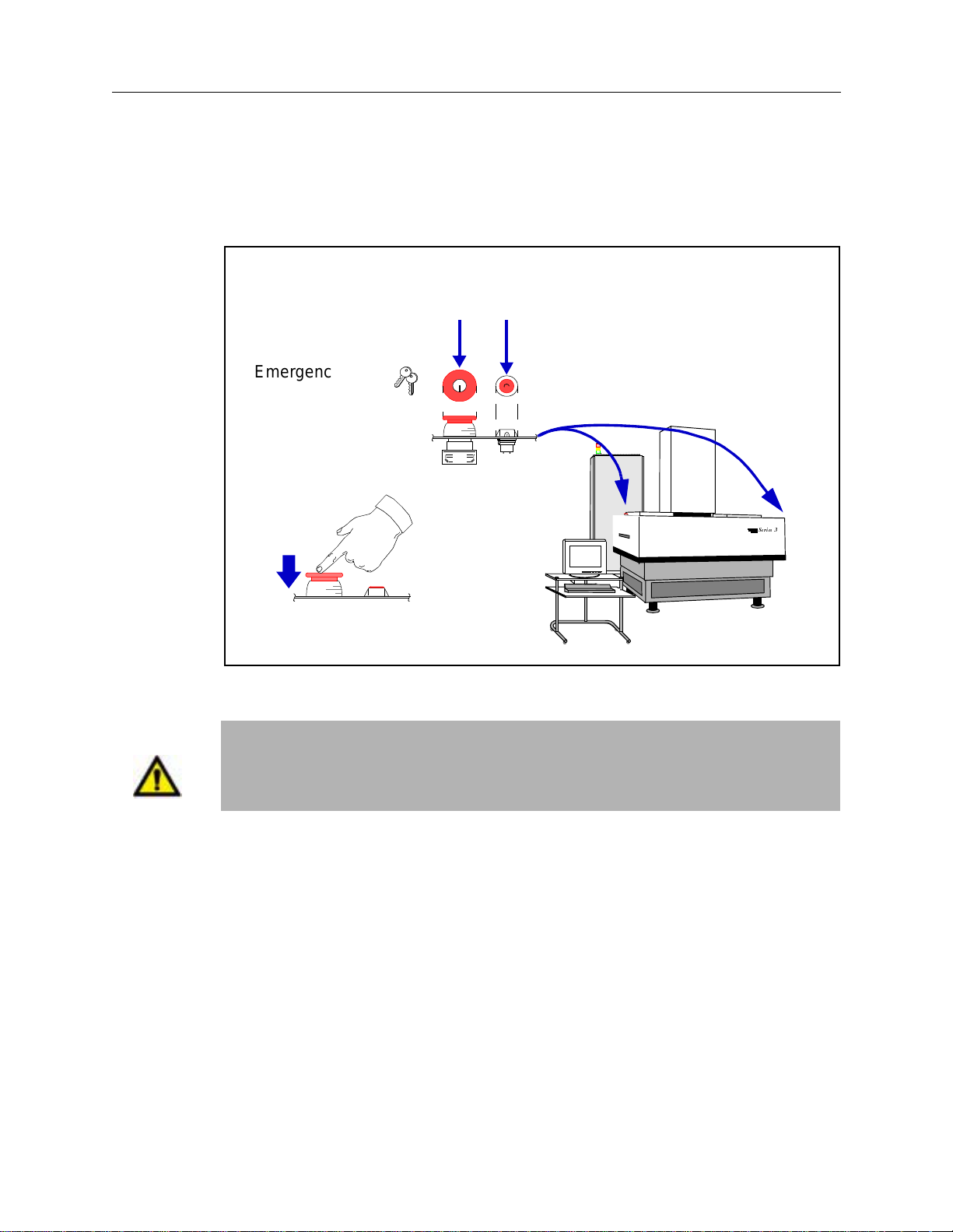
Emergency Shut Down Procedure
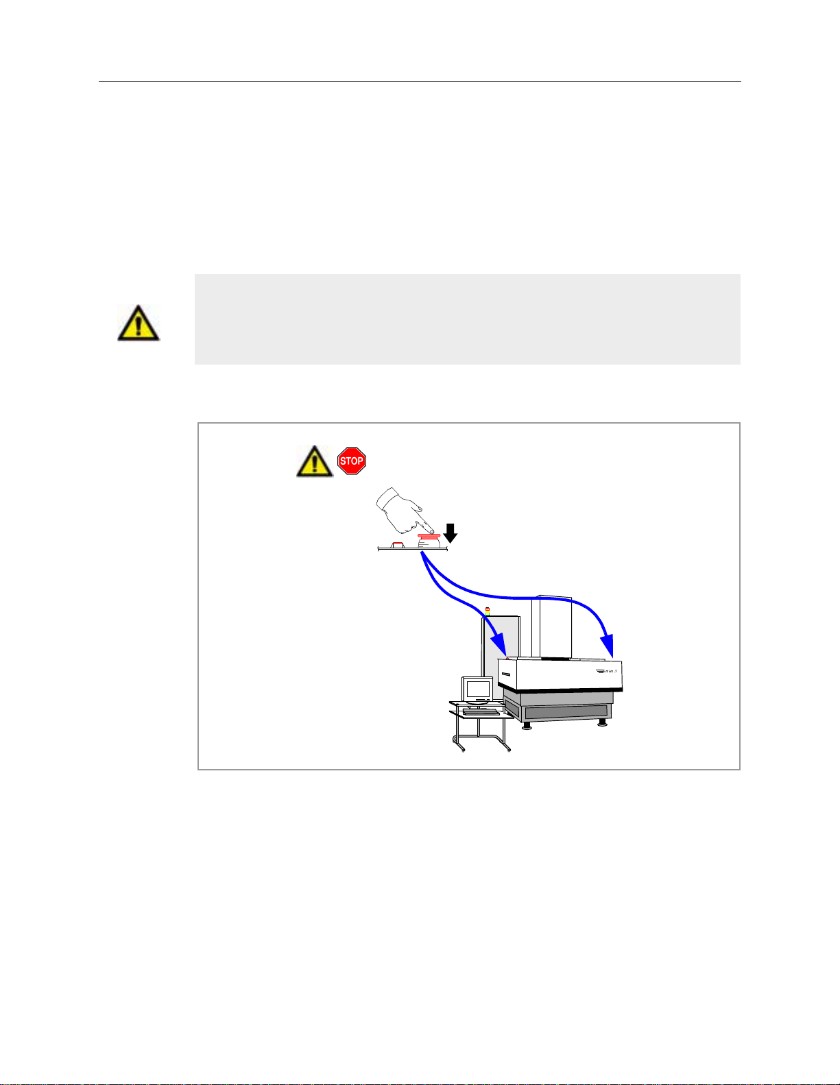
In the event of a disaster or system emergency, shut down the 5DX by pressing one
of the Emergency Stop Buttons, as shown in the figure below.
Emergency Stop Button
(Locking Switch)
Emergency Stop
Release Keys
X-ray On Indicator
5DX Series 3
5DX
6HULHV
WARNING
Emergency Stop Button
locks when pressed
120 Volt AC Power Connections are for Agilent Installed Accessories ONLY. Do
not use these connections as utility outlets. Improper handling of these
connections can result in electrical shock.
For additional information on Safety and the 5DX System, see the Chapter 2,
Safety Summary.
Page 3

Warranty and Regulatory Data
Notices
© Copyright Agilent Technologies, Inc. 2000.
All Rights Re s erved.
Printed in U S A
N7200-90041 Printed: May 2000
NOTICE
This manual is provided “as is” and is subject to change with out notice.
AGILENT TECHNOLOGIES MAKES NO WARRANTY OF ANY KIND WITH REGARD TO THIS MATERIAL, INCLUDING, BUT NOT
LIMITED TO, THE IMPLIED WARRANTIES OF NONINFRINGEMENT, MERCHANTABILITY AND FITNESS FOR A PARTICULAR
PURPOSE. Agilent Technologies shall not be liable for errors cont ai ned herein, nor for direct, indire ct , gen era l, special, incidental or consequen-
tial damages in connection with the furnishing, performance, or use of thi s ma te ri al .
Adobe™ is a trademark of Adobe Systems Incorporated which may be registered in certain jurisdictions.
Microsoft
Windows
This page lists this manual’s printing history and the system’s software revisions. If you receive manual updates or system software revisions, a new
Printing History Page will acco m pany the updates and revisions. It is important that you insert the new Pri nting History Page in the manual and
®
Manual Printing History And System Software Revisions:
®
is a U.S. registered trademark of Microsoft Corp.
and MS Windows® are U.S. registered trademarks of Microsoft Corp.
remove the old one.
Software Revision Manual Revision
7.0 Rev. A.1, May 2000
Agilent 5DX Service Guide iii
Page 4

Notices 5DX Series 3
WARRANTY
AGILENT TECHNOLOGIES WARRANTY STATEMENT
AGILENT PRODUCT DURATION OF WARRANTY
Agilent 5DX AXI System and Accessories1 (One) Year
1. Agilent warrants Agilen t h ardwar e, acce ssorie s and supplies a gainst defec ts in ma terial s and work manship f or the p er iod specified above.
If Agilent receives notice of such defects during the warrant y period, Agilent will, at its optio n, either repair or replace pro ducts whic h
prove to be defective. Repl ac ement products may be either new or like-new.
2. Agilent warrants that Agil ent sof tware will not fail to exe cute its progra mm ing i nstructio ns, for the p eriod speci fied above , due to d efect s
in material and wo rkmanship when properly in stalled and used. If Agil ent receives notice of such defects during the warranty period,
Agilent will replace software media which does not exec ut e it s programming instructions due to suc h defects.
3. Agilent does not warrant tha t the operation of Agilent product s w il l be un in te rrupted or error free. If Agilent is un able, within a reason a b le
time, to repair or repla ce any p rodu ct to a cond itio n as w arranted , cust ome r will b e entit led t o a refu nd of th e p urcha se pric e upon p rompt
return of the product.
4. Agilent products may cont ain remanufactured parts equivalent to new in performanc e or ma y have been subject to incidenta l use .
5. The warranty period begins on the date of delivery or on the date of installation if installed by Agilent. If customer schedules or delays
Agilent installation more th an 30 days after delivery, warranty begins on the 31st day from de li ve ry.
6. Warranty does not apply to defects resulting from (a) improper or inadequate maintenance or calibration, (b) software, interfacing, parts or
supplies not supplied by Agilent, (c) unauthorized modification or misuse, (d) operation outside of the published environmental
specifications for the product, or (e) improper site preparation or maintenance.
7. TO THE EXTENT ALLOWED BY LOCAL LAW, THE ABOVE WARRANTIES ARE EXCLUSIVE ANDNO OTHER WARRANTY
OR CONDITION, WHETHER WRITTEN OR ORAL, IS EXPRESSED OR IMPLIED A ND AGILENT SPECIFICALLY DISCLAIMS
ANY IMPLIED WARRANTIES OR CONDITIONS OF MERCHANTABILITY, SATISFACTORY QUALITY, AND FITNESS FOR A
PARTICULAR PURPOSE.
8. Agilent will be l iabl e for d ama ge to tang ible prop erty per in cide nt up to the g reate r of $3 00,00 0 o r th e ac tual amo unt pa id for th e p rod uct
that is the subject of th e claim, and for dama ge s for bodily injury or death, to the extent that all such damages are determ ined by a court of
competent jurisdiction to ha ve been directly caused by a defective Agilent product.
9. TO THE EXTENT ALLOWED BY LOCAL LAW, THE REMEDIES IN THIS WARRANTY STATEMENT ARE CUSTOMER’S SOLE
AND EXCLUSIVE REMEDIES. EXCEPT AS INDICATED ABOVE, IN NO EVENT WILL AGILENT OR ITS SUPPLIERS BE
LIABLE FOR LOSS OF DATA OR FOR DIRECT, SPECIAL, INCIDENTAL, CONSEQUENTIAL (INCLUDING LOST PROFIT OR
DATA), OR OTHER DAMAGE, WHETHER BASED IN CONTRACT, TORT, OR OTHERWISE.
FOR CONSUMER TRANSACTIONS IN AUSTRALIA AND NEW ZEALAND: THE WARRANTY TERMS CONTAINED IN THIS STATE-
MENT, EXCEPT TO THE EXTENT LAWFULLY PERMITTED, DO NOT EXCLUDE, RESTRICT OR MODIFY AND ARE IN ADDITION
TO THE MANDATORY STATUTORY RIGHTS APPLICABLE TO THE SALE OF THIS PRODUCT TO YOU.
iv Warranty and Regulatory Data
Page 5

5DX Series 3 Notices
PLACE OF PERFORMANCE
A. Within Agilent service travel areas, warranty and installation services for products installed by Agilent and certain other products
designated by Agilent will be perfo rmed at Customer’s facility at no charge. Outside Ag ilent service travel areas, warr anty and installat ion
services will be performed at Customer’s facility only up on Agilent’s prior agreement and Customer shall pay Agilent’s round-trip travel
expenses and applicable add it io nal expenses for such services.
B. On-site warranty services are provided only at the initial installation point. If products eligible for on-site warranty and installation services
are removed from the initial installation point, the warranty will remain in effect only if Customer purchases additional inspection or
installation services at the new site.
C. For product warranties re quiring return to Agilent, prod ucts must be returned to a service facility designated by Ag ilent. The Customer
shall prepay shipping ch arges (and shall pay al l dut y and t axes) f or pr oduct s retur ned to Agi lent for w arra nty se rvice. Exce pt for prod uct s
returned to Customer from anot he r country, Agilent shall pay for return of products to Customer.
D. Install ation and wa rranty servic es outside the country of in itial purchas e are includ ed in Agilent’s product price only if Customer pays
Agilent international prices (defined as destination local currency price, or U.S., or Geneva Export price). Service outside the country of
initial purchase is subject to the conditions regarding Agil ent service travel areas and init ial in sta ll ation point described above.
LIMITATION OF REMEDIES AND LIABILITY
A. Agilent will not be liabl e for performance delays or for non-performance, due to cause s beyond its reasonable control.
B. Pro ducts not specifically designed, man ufactured or intended for sale as part s, components or assemblies for plann ing, construction,
maintenance, or direct operat ion of a nuc lear f acility. Customer is solely liable if Produ cts or Suppo rt purch ased by Cu stome r are used for
these applications. Cu stom e r w i ll in de mnify and hold Agilent ha rm le ss from all loss, damage, ex pense or liability in co nnection with such
use.
C. Agilent will be liable for damage to tangible property per incident up to the greater of $300,000 or the actual charges paid to Agilent for the
product that is the subject of the claim, a nd for damages for bodi ly injury or death, t o the extent that al l su ch damages are de termine d by a
court of competent juri sd ic ti on to have been directly caused by a defective Product sold here under.
D. For any material breach of Support services by Agilent, Customer’s remedy and Agilent’s liability will be limited to a refund of the related
Support charges paid during the perio d of breach, up to a maximum of 12 mon ths.
E. THE REMEDIES IN THIS AGREEMENT ARE CUSTOMER’S SOLE AND EXCLUSIVE REMEDIES. EXCEPT AS INDICATED
ABOVE, IN NO EVENT WILL AGILENT OR ITS SUBCONTRACTORS BE LIABLE FOR LOSS OF DATA OR FOR DIRECT,
SPECIAL, INCIDENTAL, CONSEQUENTIAL (INCLUDING LOST PROFIT), OR OTHER DAMAGE WHETHER BASED IN
CONTRACT, TORT, OR OTHERWISE.
U.S. Government Restricted Rights
The Software and Documentation have bee n developed entirely at pr iva te expense. They are d el iv ered and licensed as “commercial computer
software” as defined in DFARS 252.227-7013 (Oct 1988), DFARS 252.211- 7015 (May 1991) or DFARS 252.22 7-7014 (Jun 1995), as a
“commercial item” as defined in F A R 2. 101(a), or as “Restricted comput er soft wa re” as defined in FAR 52.227-19 (Jun 1987) (or any equivalent
agency regulation or contract clause), whichever is applicable. You hav e onl y those rights provided for such Software and Docum entation by the
applicable FAR or DFARS claus e o r th e Agilent standard software agreement for the product involved .
Agilent 5DX Service Guid e v
Page 6

Notices 5DX Series 3
Regulatory Information
Agilent Technologies i s registered with federal and state agencies to sell and service its own X-ray equipment manufactured in Loveland,
Colorado, USA. The equipment was designed, and is used, to inspect printed circuit boards only. The X-ray equipment is classified in the United
States and internationally as an “Industrial Cabinet X-ray System”. It is not large enough for human entry. The equipme nt has be en de sig ned and
constructed to be safely us ed in any area.
The Agilent 5DX System utilizes an X-ray Tube opera ting at 160 kilovolts, 100 microa mps shielded within the lead cabinet. The tube is rated for
continuous duty operation with beam filtration of 0.07 inches Beryllium and 0.010 inches stainless steel.
The lead cabinet is fully int erlocked such that the main pow er to the X-ray Tube is removed when any access panel is opened.
When the 5DX System is installed at the customer’s site, the equipment is surveyed by trained service people. A full radia ti on safety survey is
performed and a report gener a ted. The survey is made using a Geiger Mu eller and a health ph ysics ion chamber according to procedures on record
with the CDRH.
The end user is responsible for regi ster i ng th e equipment with their local and state authorities.
Agilent Technologies warrants that the 5DX automated process test systems meets X-ray safety reg ulations in the following countries:
Canada Reference Statutes of Canada Chapter R-1, Chapter 1370, Schedule 1, Section 15, Schedule II and Part XV.
England Reference BS5724, (ISO 9000 601-1).
Germany Reference BGBII, S.114 & Din 54113 and the “Law on the Protection Against Injury or Damage Due to X-Rays” a.k.a. “X-Ray
Decree”.
Japan Reference Ministry of Labor, Industrial Safety and Health, Law #57 a nd Ca binet ordinance #38.
Korea Reference Presidential Decree, Article 65, Chapter VII, of the Atomic Energy Act.
The Nordic Regions of Denmark, Finland, Iceland, Norway and Sweden,
Reference the Radiat io n Protection Institutes and the Radiation Protection Act.
United States
Regulation 21CFR 1010.2 , 10 10. 3, and 1020.40 administered by th e D e partment of Health and Human Servi c es, Food and Drug
Administration, Center for D evices and Radiological Health (CDRH).
vi Warranty and Regulatory Data
Page 7
5DX Series 3 Safety Information
Safety Information
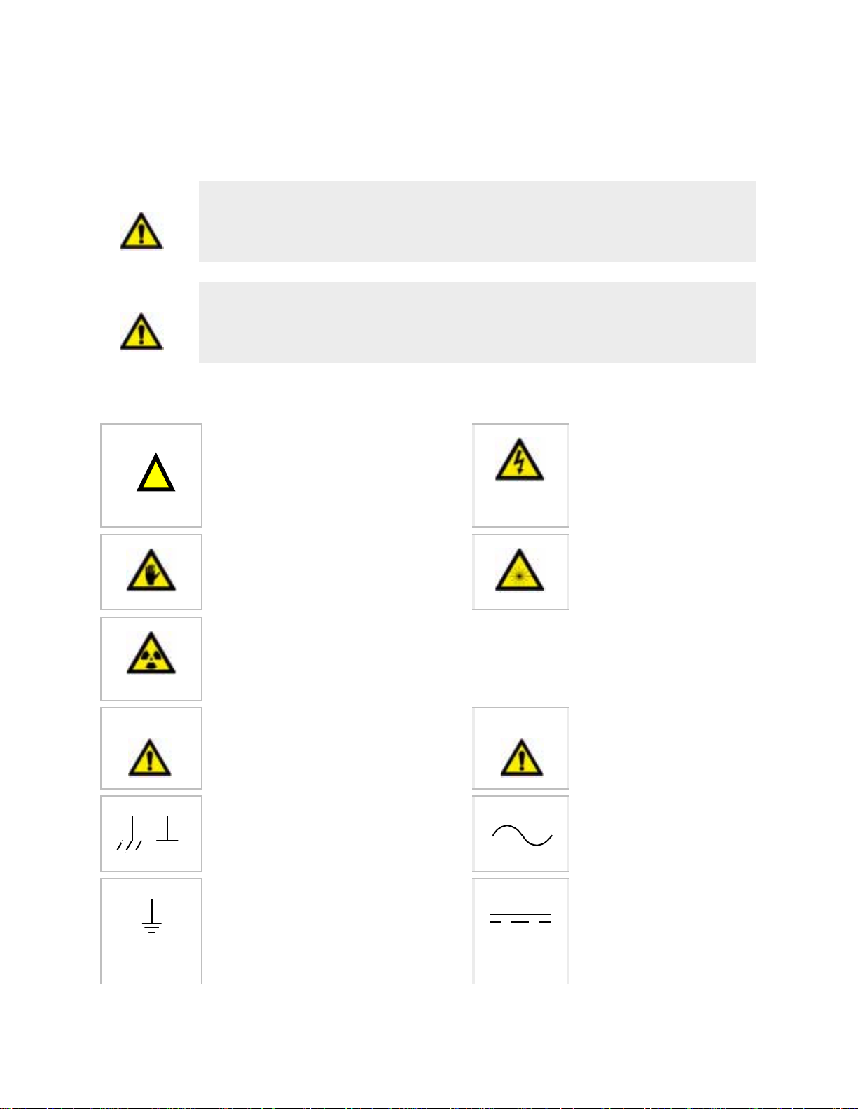
WARNING
WARNING
!
This product produces X-rays. Do not attempt to open any part of the product.
Exposure to X-rays can cause serious bodily injury. Refer all servicing to
service-trained personnel.
This product produces X-rays. Do not oper ate t his produc t or turn on the X-r ays
source unless all shielding is in place. Operation without shielding in place can
result in seriou s bod ily in ju ry.
SAFETY SYMBOLS
Instruction symbol affixed to
product. Indicates that the user must
refer to the manual for spe ci fi c
WARNING or CAUTION
information to avoid personal injury
or damage to the product.
Calls attention to pinch hazards.
Keep hands away to avoid injur y.
Indicates hazardous voltage.
Indicates thi s equipment produces
laser radiation when energized.
WARNING
Indicates this equipment pro duc e s Xrays when energized.
Calls attention to a procedure,
practice, or condition that coul d
result in bodily injury or death.
Frame or chassis ground terminal —
typically connects to the equipment’s
metal frame.
Indicates the field wiring termina l
that must be connecte d to earth
ground before operating the
equipment — prote c ts against
electrical shock in case of fa ult .
Caution
Calls attention to a proced ure,
practice, or condition that could
cause damage to equipment or
permanent loss of data.
Alternating current (ac).
Direct current (dc).
Agilent 5DX Service Guide vii
Page 8

Safety Informa tion 5 D X S e ries 3
WARNINGS
The following general safe ty precautions must be observ ed during all phases of operati on, service, and repair of this prod uct. Failure to comply
with these precautions or with specific warnings elsewhere in this manual violates safety standards of design, manufacture, and intended use of the
product. Agilent Technologi es, Inc. assumes no liability for the Customer ’s failure to comply with these requirements.
Ground the Equipment For Safety Class 1 equipment (equipment having a protective earth terminal), an uninterruptible safety earth ground must
be provided from the mains pow er source to the product input wiring terminals or supplied pow er cab le .
DO NOT operate the product in an explosive atmosphere or in the presence of flammable gases or fumes.
For continued protection aga in s t fir e, replace the line fuses(s) only with the fuse(s) of the same voltage and current rating and type. DO NOT use
repaired fuses or short-circuited fuse holders.
Keep away from live circuits: Operating personnel must not remove equipment covers or shields. Procedures involving the removal of covers or
shields are for use by service-train ed personnel only. Under certain conditions, dangerous voltages ma y exi s t even with the equipment switched
off. To avoid dangerous electrical shock, DO NOT perform procedures involv ing cov er or shield removal unless you are qu alified to do so.
DO NOT operate damaged equipment: Whenever it is possible that the safety protection features built into this product have been impaired,
either through physical damage, excessive moisture, or by any other reason, REMOVE POWER and do not use the product until safe operation can
be verified by service-trained personnel. If necessary, return the product to a Agilent Technologies Sales and Service Office for service and repair
to ensure that safety features are maintained.
Do not service or adjust alone: Do not attempt internal service or adjust m en t unl ess a nother person, capable of ren de ring first aid and
resuscitation, is present.
Do not substitute parts or modify equipment: Because of the danger of introducing additional hazards, do not install substitute parts or perform
any unauthorized mod ifi ca tion to the product. Return th e product to a Agilent Tech nologies Sales and Service Offi ce for se rvice and repair to
ensure that safe ty fea tures are maintained.
viii Warranty and Regulatory Data
Page 9

5DX Series 3 Safety Information
DECLARATION OF CONFORMITY
according to ISO/IEC Guide 22 and EN 45014
Manufacturer’s Name: Agilent Technolo gies, Inc.
Manufacturin g Te st Division
Manufacturer’s Address: 815 14th Street S .W.
Loveland, Colorado 80537
declares, that the products: Agilent Model 5DX Systems
and to which this declaration relates, are in conformity with the protection requirements of:
The EMC Directive 89/336/EEC (inclusive 93/68/EEC) and carries the “CE” marking accordingly.
Attestation is provided according to article 10 (2) of the Directive by a Technical Construction File.
Technical File Number: 95-0900-003-TCF Rev: A Dated: 31 March, 1995
The following standards are referenced in the file:
EMC: CISPR 11:1990/EN55011 (1991)
IEC 801-2:1991/EN50082-1 (1992)
IEC 801-3:1984/EN50082-1 (1992)
IEC 801-4:1988/EN50082-1 (1992)
A Technical Report/Certificate has been issued in accordance with P art V (Reg 50) of the UK
Regulations (SI 1992 No. 2372) by a UK appointed Competent Body, namely,
Interference Technology International Limited
41-42 Shrivenham Hundred Business Park
Shrivenham, Swindon, Wilts. SN6 8TZ
England, UK
Certificate Number: C134FPI1.JES Dated: 1 April, 1996
Supplementary Information:
This product also herewith complie s with th e require m ents of th e Low Voltage Directive 73/23/EEC
(inclusive 93/68/EEC).
Safety: IEC 1010-1 (1990) I ncl. Amend 1 (1992)/EN6 1010-1 (1993)
CSA C22.2 #1010.1 (1992)
UL 3111
April 1, 1996 Loveland Quality Manager
European Contact: Your local Agilent Technolo gi es Sal es a nd Se rvice Office or Agilent Techno logies GmbH,
Department HQ-TRE, Herrenberger Straße 130, D-71034 Böbli ngen (FAX: +49-7031-143 143).
Agilent 5DX Service Guid e ix
Page 10
Electromagnetic Compatibility Requirements 5DX Series 3
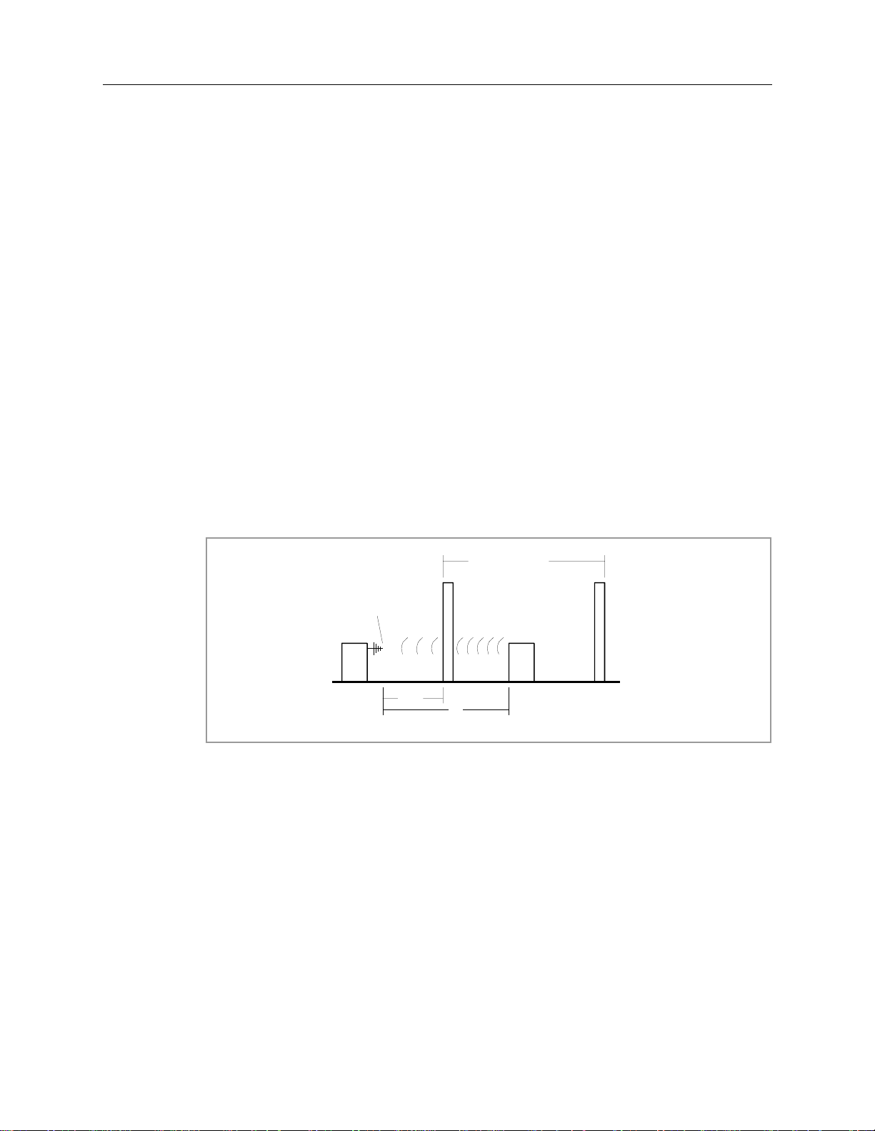
Electromagnetic Compatibility Requirements
This product complies with EN 55011 (CISPR 11) Group 1, Class A for conduc ti ng emissions. The product excee ds the EN 55011 (CISPR 11)
Group 1, Class A limit for radiated emissi ons by less than 10 dB when measured on a test site at a distance of 30 meters. Therefore, some site
preparations may have to be don e in order to comply with the Class A lim it in th e frequency range of 30 MHz to 1 GHz for ra diated emissions at
30 meters from the exterior wall of a buil di ng i n w hi ch t he equi pm ent is installed. See the figure bel ow for an illustration of the site calculations.
To obtain the necessary at te nua ti on at the Customer’s site, perfor m t he se ca lc ul at ions (if the calculated site attenuation (A) is less than 10 dB,
contact the Technical Regulatory Support Engine er (T RSE) in your country):
1. The attenuation of a concrete wall (W) (without any openings) = 10 dB
2. The distance (D) (the distance from the equipment to the exterior wall plus 30 meters) increases the attenuation by X and can be calculated
as follows:
X = 20 * log (D/30)
Where: X = attenuation in dB
D = distance in meters
3. The total attenuation (A) is calculated as follows:
A = n * W + X
Where: A = total attenuation in dB
n = number of concrete wa ll s w ith in dist ance D
W = 10 (dB)
Building in which the
Equipment is installed
W
Measuring Po i nt
30 m
D
Equipme nt
QBEMC.WPG
Figure 1: Electromagnetic Emission Measurement
x Warranty and Regulatory Data
Page 11
5DX Series 3 Emergency Stop
Emergency Stop
The Emergency Stop Subsystem is used to quickly shutdown the power to the
Agilent 5DX Main Cabinet. The Emergency Stop Subsystem is intended for crisis
situations only and should not be used as the normal means to stop the Agilent
5DX.
Caution
The Emergency Stop Buttons are intended for use in emergency situations
and should not be used for normal system shutdown. Repeated misuse of
only
the Emergency Stop Buttons will eventually cause damage to certain
components or the loss of dat a or both.
The 5DX System is equipped with two Emergency Stop Buttons. Refer to Figure 2
for their locations.
Push down the Emergency Stop Button, or
switch the AC “Mains” to the “0” or off posit ion
in an emergency situation.
The Emergency
Stop Butt on locks
OFF when pushed.
View from the front of the
5DX System.
5DX
6HULHV
Figure 2: Emergency Stop Locations
The Emergency Stop Buttons are located on either side of the 5DX System Main
Cabinet just above the input or output barriers. When either Emergency Stop
Button is pressed it will immediately interrupt the switched system power. The
Emergency Stop Button will lock in the power off position and remain in the
locked position until released with the Emergency Stop release key. See the
Agilent 5DX Power Subsystem chapter of the Agilent 5DX Series 3 Service
Guide for a step-by-step procedure for restoring system power after an Emergency
Stop procedure has been performed.
Agilent 5DX Service Guid e xi
Page 12

Emergency Stop 5DX Series 3
xii Warranty and Regulatory Data
Page 13

Table of Contents
Warranty and Regulatory Data
Notices . . . . . . . . . . . . . . . . . . . . . . . . . . . . . . . . . . . . . . . . . . . . . . . . . . . . . . . . . . . . .iii
Safety Information. . . . . . . . . . . . . . . . . . . . . . . . . . . . . . . . . . . . . . . . . . . . . . . . . . . vii
Electromagnetic Compatibility Requirements. . . . . . . . . . . . . . . . . . . . . . . . . . . . . . . x
Emergency Stop . . . . . . . . . . . . . . . . . . . . . . . . . . . . . . . . . . . . . . . . . . . . . . . . . . . . . .xi
1. Introduction and Overview
What’s in the Agilent 5DX Service Guide?. . . . . . . . . . . . . . . . . . . . . . . . . . . . . . . .1-2
What’s New With the Series 3? . . . . . . . . . . . . . . . . . . . . . . . . . . . . . . . . . . . . . . . . .1-3
What is the 5DX Automated X-ray Inspection System? . . . . . . . . . . . . . . . . . . . . . .1-4
How It Works. . . . . . . . . . . . . . . . . . . . . . . . . . . . . . . . . . . . . . . . . . . . . . . . . . . .1-4
The 5DX System Process . . . . . . . . . . . . . . . . . . . . . . . . . . . . . . . . . . . . . . . . . .1-6
5DX Overview. . . . . . . . . . . . . . . . . . . . . . . . . . . . . . . . . . . . . . . . . . . . . . . . . . . . . .1-7
Electronics Bay . . . . . . . . . . . . . . . . . . . . . . . . . . . . . . . . . . . . . . . . . . . . . . . . . .1-8
Subsystems of the Agilent 5DX System . . . . . . . . . . . . . . . . . . . . . . . . . . . . . .1-10
Safety Interlock Subsystem. . . . . . . . . . . . . . . . . . . . . . . . . . . . . . . . . . . . . . . .1-11
X-ray High Voltage Power Supply . . . . . . . . . . . . . . . . . . . . . . . . . . . . . . . . . .1-11
Panel Handling Subsystem . . . . . . . . . . . . . . . . . . . . . . . . . . . . . . . . . . . . . . . .1-12
Surface Map Subsystem . . . . . . . . . . . . . . . . . . . . . . . . . . . . . . . . . . . . . . . . . .1-12
Imaging Subsystem. . . . . . . . . . . . . . . . . . . . . . . . . . . . . . . . . . . . . . . . . . . . . .1-12
Pneumatics Subsystem . . . . . . . . . . . . . . . . . . . . . . . . . . . . . . . . . . . . . . . . . . .1-12
System Controller and Expansion Chassis . . . . . . . . . . . . . . . . . . . . . . . . . . . .1-12
User Interface . . . . . . . . . . . . . . . . . . . . . . . . . . . . . . . . . . . . . . . . . . . . . . . . . .1-13
Agilent 5DX Service Gui d e xiii
Page 14

2. Safety Summary
Safety Summary. . . . . . . . . . . . . . . . . . . . . . . . . . . . . . . . . . . . . . . . . . . . . . . . . . . . .2-2
Warnings . . . . . . . . . . . . . . . . . . . . . . . . . . . . . . . . . . . . . . . . . . . . . . . . . . . . . . . .2-3
Emergency Stop . . . . . . . . . . . . . . . . . . . . . . . . . . . . . . . . . . . . . . . . . . . . . . . . . . . . .2-4
Emergency Procedures. . . . . . . . . . . . . . . . . . . . . . . . . . . . . . . . . . . . . . . . . . . . . . . .2-6
X-ray Safety. . . . . . . . . . . . . . . . . . . . . . . . . . . . . . . . . . . . . . . . . . . . . . . . . . . . . . . .2-8
Effects of Radiation. . . . . . . . . . . . . . . . . . . . . . . . . . . . . . . . . . . . . . . . . . . . . . .2-8
X-ray Dose Limits. . . . . . . . . . . . . . . . . . . . . . . . . . . . . . . . . . . . . . . . . . . . . . . .2-8
Definition of a Cabinet X-ray System. . . . . . . . . . . . . . . . . . . . . . . . . . . . . . . . .2-9
Built-In Safety Features. . . . . . . . . . . . . . . . . . . . . . . . . . . . . . . . . . . . . . . . . . . .2-9
Registration Requirements . . . . . . . . . . . . . . . . . . . . . . . . . . . . . . . . . . . . . . . . .2-9
X-ray Safety. . . . . . . . . . . . . . . . . . . . . . . . . . . . . . . . . . . . . . . . . . . . . . . . . . . . . . .2-10
X-ray Safety Precautions. . . . . . . . . . . . . . . . . . . . . . . . . . . . . . . . . . . . . . . . . .2-10
Safety Requirements . . . . . . . . . . . . . . . . . . . . . . . . . . . . . . . . . . . . . . . . . . . . .2-11
High Voltage Safety . . . . . . . . . . . . . . . . . . . . . . . . . . . . . . . . . . . . . . . . . . . . . . . . .2-11
High Voltage Subsystem . . . . . . . . . . . . . . . . . . . . . . . . . . . . . . . . . . . . . . . . . .2-11
Power Distribution Unit (PDU). . . . . . . . . . . . . . . . . . . . . . . . . . . . . . . . . . . . .2-12
. . . . . . . . . . . . . . . . . . . . . . . . . . . . . . . . . . . . . . . . . . . . . . . . . . . . . . . . . . . . . .2-12
Mechanical Safety . . . . . . . . . . . . . . . . . . . . . . . . . . . . . . . . . . . . . . . . . . . . . .2-12
Laser Safety . . . . . . . . . . . . . . . . . . . . . . . . . . . . . . . . . . . . . . . . . . . . . . . . . . . . . . .2-14
Additional Information . . . . . . . . . . . . . . . . . . . . . . . . . . . . . . . . . . . . . . . . . . . . . .2-14
Agilent 5DX System Training. . . . . . . . . . . . . . . . . . . . . . . . . . . . . . . . . . . . . .2-15
5DX Series 3
3. Safety Interlock Subsystem
Overview . . . . . . . . . . . . . . . . . . . . . . . . . . . . . . . . . . . . . . . . . . . . . . . . . . . . . . . . . .3-2
Safety Interlock Controller. . . . . . . . . . . . . . . . . . . . . . . . . . . . . . . . . . . . . . . . . . . . .3-3
Normal Operation LEDs . . . . . . . . . . . . . . . . . . . . . . . . . . . . . . . . . . . . . . . . . . .3-4
Diagnostic LEDs. . . . . . . . . . . . . . . . . . . . . . . . . . . . . . . . . . . . . . . . . . . . . . . . .3-4
Watchdog Timer . . . . . . . . . . . . . . . . . . . . . . . . . . . . . . . . . . . . . . . . . . . . . . . . .3-6
Safety Interlocks . . . . . . . . . . . . . . . . . . . . . . . . . . . . . . . . . . . . . . . . . . . . . . . . . . . .3-6
Safety Interlock Locations . . . . . . . . . . . . . . . . . . . . . . . . . . . . . . . . . . . . . . . . . . . . .3-7
Safety Interlock Switches. . . . . . . . . . . . . . . . . . . . . . . . . . . . . . . . . . . . . . . . . . . . . .3-8
Safety Interlock Chains . . . . . . . . . . . . . . . . . . . . . . . . . . . . . . . . . . . . . . . . . . . . . .3-10
Operator Control Console . . . . . . . . . . . . . . . . . . . . . . . . . . . . . . . . . . . . . . . . . . . .3-14
Adjusting the Safety Interlocks on the Inner Barrier. . . . . . . . . . . . . . . . . . . . .3-15
Adjusting the Outer Barrier’s Primary Safety Interlock . . . . . . . . . . . . . . . . . .3-18
Adjusting the Outer Barrier’s Secondary Safety Interlock . . . . . . . . . . . . . . . .3-23
xiv Table of Contents
Page 15

5DX Series 3
4. Power Subsystem
Overview . . . . . . . . . . . . . . . . . . . . . . . . . . . . . . . . . . . . . . . . . . . . . . . . . . . . . . . . . .4-2
Power Distribution Unit. . . . . . . . . . . . . . . . . . . . . . . . . . . . . . . . . . . . . . . . . . . . . . .4-4
Input Specifications. . . . . . . . . . . . . . . . . . . . . . . . . . . . . . . . . . . . . . . . . . . . . . .4-5
Switched Output Terminals . . . . . . . . . . . . . . . . . . . . . . . . . . . . . . . . . . . . . . . . .4-5
Unswitched Output Terminals. . . . . . . . . . . . . . . . . . . . . . . . . . . . . . . . . . . . . . .4-6
Controls and Indicators . . . . . . . . . . . . . . . . . . . . . . . . . . . . . . . . . . . . . . . . . . . .4-6
High/Low Line Monitoring/Protection . . . . . . . . . . . . . . . . . . . . . . . . . . . . . . . .4-7
Emergency Shutdown . . . . . . . . . . . . . . . . . . . . . . . . . . . . . . . . . . . . . . . . . . . . .4-7
PDU Circuit Breakers and Fuses . . . . . . . . . . . . . . . . . . . . . . . . . . . . . . . . . . .4-8
Wiring Diagrams . . . . . . . . . . . . . . . . . . . . . . . . . . . . . . . . . . . . . . . . . . . . . . . . . . . .4-9
Low Voltage Assembly . . . . . . . . . . . . . . . . . . . . . . . . . . . . . . . . . . . . . . . . . . . . . .4-15
Focus Coil Power Supply . . . . . . . . . . . . . . . . . . . . . . . . . . . . . . . . . . . . . . . . . . . . .4-15
VacIon Pump Power Supply . . . . . . . . . . . . . . . . . . . . . . . . . . . . . . . . . . . . . . . . . .4-17
Camera Power Supply . . . . . . . . . . . . . . . . . . . . . . . . . . . . . . . . . . . . . . . . . . . . . . .4-17
X-ray High Voltage Power Supply. . . . . . . . . . . . . . . . . . . . . . . . . . . . . . . . . . . . . .4-18
Emergency Stop Buttons and X-Ray Indicators . . . . . . . . . . . . . . . . . . . . . . . . . . .4-20
Long Term Shutdown For the Agilent 5DX System . . . . . . . . . . . . . . . . . . . . . . . .4-22
Startup Procedure For the Agilent 5DX System . . . . . . . . . . . . . . . . . . . . . . . . . . .4-24
Recover From an Emergency Stop . . . . . . . . . . . . . . . . . . . . . . . . . . . . . . . . . .4-28
System Status Beacon . . . . . . . . . . . . . . . . . . . . . . . . . . . . . . . . . . . . . . . . . . . .4-30
5. Panel Handling Subsystem
Panel Handling Subsystem Introduction . . . . . . . . . . . . . . . . . . . . . . . . . . . . . . . . . .5-2
Agilent 5DX Panel Handling Configurations . . . . . . . . . . . . . . . . . . . . . . . . . . . . . .5-4
Panel Handling Modes . . . . . . . . . . . . . . . . . . . . . . . . . . . . . . . . . . . . . . . . . . . .5-4
Configuring a System for Right to Left Flow Through. . . . . . . . . . . . . . . . . . . .5-6
Dual Panel Test Mode . . . . . . . . . . . . . . . . . . . . . . . . . . . . . . . . . . . . . . . . . . . . .5-6
SMEMA Interface Standards. . . . . . . . . . . . . . . . . . . . . . . . . . . . . . . . . . . . . . . . . . .5-6
Introduction. . . . . . . . . . . . . . . . . . . . . . . . . . . . . . . . . . . . . . . . . . . . . . . . . . . . .5-6
Communication Signals . . . . . . . . . . . . . . . . . . . . . . . . . . . . . . . . . . . . . . . . . . .5-8
SMEAMA Connections through the Digital I/O Assembly . . . . . . . . . . . . . . .5-11
Panel Handling Subsystem Components . . . . . . . . . . . . . . . . . . . . . . . . . . . . . . . . .5-13
X-ray Cabinet and Barriers . . . . . . . . . . . . . . . . . . . . . . . . . . . . . . . . . . . . . . . . . . .5-14
Outer Cabinet and Outer Barriers . . . . . . . . . . . . . . . . . . . . . . . . . . . . . . . . . . .5-14
Inner Cabinet and Inner Barrier. . . . . . . . . . . . . . . . . . . . . . . . . . . . . . . . . . . . .5-15
XYZ Stage Assembly. . . . . . . . . . . . . . . . . . . . . . . . . . . . . . . . . . . . . . . . . . . . . . . .5-16
X-Axis and Y-Axis Servomotors. . . . . . . . . . . . . . . . . . . . . . . . . . . . . . . . . . . .5-17
Z-Axis Stepper Motors . . . . . . . . . . . . . . . . . . . . . . . . . . . . . . . . . . . . . . . . . . .5-19
Agilent 5DX Service Guid e xv
Page 16

5DX Series 3
XYZ Stage Panel Conveyor Assemblies. . . . . . . . . . . . . . . . . . . . . . . . . . . . . .5-20
XYZ Stage Panel Conveyor Belts. . . . . . . . . . . . . . . . . . . . . . . . . . . . . . . . . . .5-22
Motion Control Assembly . . . . . . . . . . . . . . . . . . . . . . . . . . . . . . . . . . . . . . . . . . . .5-28
Motion Control Diagnostic Access Module . . . . . . . . . . . . . . . . . . . . . . . . . . .5-29
Servo Modules. . . . . . . . . . . . . . . . . . . . . . . . . . . . . . . . . . . . . . . . . . . . . . . . . .5-32
Backplane . . . . . . . . . . . . . . . . . . . . . . . . . . . . . . . . . . . . . . . . . . . . . . . . . . . . .5-33
Automatic Wi dth Adj ust ( AWA) an d Z- Axis Stepper Drivers . . . . . . . . . . . . .5-33
Motion Enable Control . . . . . . . . . . . . . . . . . . . . . . . . . . . . . . . . . . . . . . . . . . .5-34
Motor Relay Control . . . . . . . . . . . . . . . . . . . . . . . . . . . . . . . . . . . . . . . . . . . . .5-35
Motion Controller PCI Cards. . . . . . . . . . . . . . . . . . . . . . . . . . . . . . . . . . . . . . . . . .5-38
Motion Controller PCI 1 . . . . . . . . . . . . . . . . . . . . . . . . . . . . . . . . . . . . . . . . . .5-38
Motion Controller PCI 2 . . . . . . . . . . . . . . . . . . . . . . . . . . . . . . . . . . . . . . . . . .5-41
Digital I/O Assembly. . . . . . . . . . . . . . . . . . . . . . . . . . . . . . . . . . . . . . . . . . . . . . . .5-42
Panel Handling Software . . . . . . . . . . . . . . . . . . . . . . . . . . . . . . . . . . . . . . . . . . . . .5-51
6. Pneumatic Subsystem
Introduction . . . . . . . . . . . . . . . . . . . . . . . . . . . . . . . . . . . . . . . . . . . . . . . . . . . . . . . . 6 -2
Pneumatic Subsystem Components . . . . . . . . . . . . . . . . . . . . . . . . . . . . . . . . . . . . . .6-3
Pneumatic Gauge, Regulator, and Filter Assembly. . . . . . . . . . . . . . . . . . . . . . .6-4
Main Safety Valve . . . . . . . . . . . . . . . . . . . . . . . . . . . . . . . . . . . . . . . . . . . . . . . .6-6
Internal Manifold. . . . . . . . . . . . . . . . . . . . . . . . . . . . . . . . . . . . . . . . . . . . . . . . .6-7
Inner Barrier . . . . . . . . . . . . . . . . . . . . . . . . . . . . . . . . . . . . . . . . . . . . . . . . . . . .6-8
Barrier Operation. . . . . . . . . . . . . . . . . . . . . . . . . . . . . . . . . . . . . . . . . . . . . . . .6-11
Adjusting the Air Cylinder . . . . . . . . . . . . . . . . . . . . . . . . . . . . . . . . . . . . . . . .6-14
Other Inner Barrier Components. . . . . . . . . . . . . . . . . . . . . . . . . . . . . . . . . . . .6-15
Adjustment/Replacement of the Inner Barrier Encoder . . . . . . . . . . . . . . . . . .6-16
Setting the Positions for the Encoder . . . . . . . . . . . . . . . . . . . . . . . . . . . . . . . .6-20
xvi Table of Contents
Page 17

5DX Series 3
7. Surface Map Subsyste m
Overview . . . . . . . . . . . . . . . . . . . . . . . . . . . . . . . . . . . . . . . . . . . . . . . . . . . . . . . . . .7-2
XYZ Panel Orientation (Loaded). . . . . . . . . . . . . . . . . . . . . . . . . . . . . . . . . . . . . . . .7-2
Panel Alignment . . . . . . . . . . . . . . . . . . . . . . . . . . . . . . . . . . . . . . . . . . . . . . . . .7-3
Alignment Accuracy . . . . . . . . . . . . . . . . . . . . . . . . . . . . . . . . . . . . . . . . . . . . . .7-3
Surface Map. . . . . . . . . . . . . . . . . . . . . . . . . . . . . . . . . . . . . . . . . . . . . . . . . . . . . . . .7-5
OFFSET (X&Y) . . . . . . . . . . . . . . . . . . . . . . . . . . . . . . . . . . . . . . . . . . . . . . . . .7-5
Laser Adjustment . . . . . . . . . . . . . . . . . . . . . . . . . . . . . . . . . . . . . . . . . . . . . . . .7-5
Surface Map Subsystem Components . . . . . . . . . . . . . . . . . . . . . . . . . . . . . . . . . . . .7-6
Surface Map Laser. . . . . . . . . . . . . . . . . . . . . . . . . . . . . . . . . . . . . . . . . . . . . . . .7-6
Laser Theory of Operation . . . . . . . . . . . . . . . . . . . . . . . . . . . . . . . . . . . . . . . . .7-8
Laser View Camera . . . . . . . . . . . . . . . . . . . . . . . . . . . . . . . . . . . . . . . . . . . . . . .7-9
Panel View Camera. . . . . . . . . . . . . . . . . . . . . . . . . . . . . . . . . . . . . . . . . . . . . .7-10
8. Imaging Subsystem
Overview . . . . . . . . . . . . . . . . . . . . . . . . . . . . . . . . . . . . . . . . . . . . . . . . . . . . . . . . . .8-2
Image Generation Process . . . . . . . . . . . . . . . . . . . . . . . . . . . . . . . . . . . . . . . . . . . . .8-3
Image Acquisition Process. . . . . . . . . . . . . . . . . . . . . . . . . . . . . . . . . . . . . . . . . . . . .8-6
Image Acquisition Theory of Operation . . . . . . . . . . . . . . . . . . . . . . . . . . . . . . .8-6
Image Analysis. . . . . . . . . . . . . . . . . . . . . . . . . . . . . . . . . . . . . . . . . . . . . . . . . . . . . .8-8
Imaging Subsystem Components. . . . . . . . . . . . . . . . . . . . . . . . . . . . . . . . . . . . . . . .8-9
Image Generation Components . . . . . . . . . . . . . . . . . . . . . . . . . . . . . . . . . . . . . .8-9
Image Acquisition Components . . . . . . . . . . . . . . . . . . . . . . . . . . . . . . . . . . . . .8-9
Image Analysis Components. . . . . . . . . . . . . . . . . . . . . . . . . . . . . . . . . . . . . . . .8-9
System Controller . . . . . . . . . . . . . . . . . . . . . . . . . . . . . . . . . . . . . . . . . . . . . . . .8-9
X-ray Scan Controller . . . . . . . . . . . . . . . . . . . . . . . . . . . . . . . . . . . . . . . . . . . .8-10
Rotary Scintillator Assembly . . . . . . . . . . . . . . . . . . . . . . . . . . . . . . . . . . . . . .8-20
Interface Card . . . . . . . . . . . . . . . . . . . . . . . . . . . . . . . . . . . . . . . . . . . . . . . . . .8-24
Frame Grabbers. . . . . . . . . . . . . . . . . . . . . . . . . . . . . . . . . . . . . . . . . . . . . . . . .8-25
X-ray Image Camera. . . . . . . . . . . . . . . . . . . . . . . . . . . . . . . . . . . . . . . . . . . . .8-25
9. System Controller
Overview . . . . . . . . . . . . . . . . . . . . . . . . . . . . . . . . . . . . . . . . . . . . . . . . . . . . . . . . . .9-2
System Controller . . . . . . . . . . . . . . . . . . . . . . . . . . . . . . . . . . . . . . . . . . . . . . . . . . .9-2
Expansion Chassis . . . . . . . . . . . . . . . . . . . . . . . . . . . . . . . . . . . . . . . . . . . . . . . . . . .9-3
Agilent 5DX Service Guide xvii
Page 18

10. Maintenance
Introduction . . . . . . . . . . . . . . . . . . . . . . . . . . . . . . . . . . . . . . . . . . . . . . . . . . . . . . . 10-2
Preventative Maintenance (PM) Checklist . . . . . . . . . . . . . . . . . . . . . . . . . . . . . . .10-4
General Maintenance. . . . . . . . . . . . . . . . . . . . . . . . . . . . . . . . . . . . . . . . . . . . . . . .10-7
Electronics Bay Maintenance. . . . . . . . . . . . . . . . . . . . . . . . . . . . . . . . . . . . . . . . .10-15
Main Cabinet Maintenance . . . . . . . . . . . . . . . . . . . . . . . . . . . . . . . . . . . . . . . . . .10-22
Software Diagnostics. . . . . . . . . . . . . . . . . . . . . . . . . . . . . . . . . . . . . . . . . . . . . . .10-42
5DX Series 3
Maintenance Activity Conventions. . . . . . . . . . . . . . . . . . . . . . . . . . . . . . . . . .10-3
Check the Operation of the System Status Beacon . . . . . . . . . . . . . . . . . . . . . .10-7
Check X-ray High Voltage Power Supply Status . . . . . . . . . . . . . . . . . . . . . . .10-9
Check X-ray Tube Dielectric Pressure . . . . . . . . . . . . . . . . . . . . . . . . . . . . . .10-11
Check the Panel View Camera Light. . . . . . . . . . . . . . . . . . . . . . . . . . . . . . . .10-13
Check the Focus Coil Power Supply Setting. . . . . . . . . . . . . . . . . . . . . . . . . .10-15
Clean All Filters and Fans. . . . . . . . . . . . . . . . . . . . . . . . . . . . . . . . . . . . . . . .10-18
Check the Vac-Ion Power Supply . . . . . . . . . . . . . . . . . . . . . . . . . . . . . . . . . .10-22
Check the System Air Pressure/Low Pressure Regulator . . . . . . . . . . . . . . . .10-26
Inspect the Laser Camera Lights. . . . . . . . . . . . . . . . . . . . . . . . . . . . . . . . . . .10-27
Inspect Main Cabinet Cables. . . . . . . . . . . . . . . . . . . . . . . . . . . . . . . . . . . . . .10-29
Inspect the XYZ Stage Conveyor Belts. . . . . . . . . . . . . . . . . . . . . . . . . . . . . .10-30
Inspect Left and Right PIP Sensor Flags. . . . . . . . . . . . . . . . . . . . . . . . . . . . .10-31
Lubricate the XYZ Stage Lead Screws and Rails . . . . . . . . . . . . . . . . . . . . . .10-33
Clean and Inspect the Rotary Scintillator Shield. . . . . . . . . . . . . . . . . . . . . . .10-36
Check the Auto Width Adjust . . . . . . . . . . . . . . . . . . . . . . . . . . . . . . . . . . . . .10-37
Clean and Inspect the Main Cabinet . . . . . . . . . . . . . . . . . . . . . . . . . . . . . . . .10-39
Lubricate XYZ Stage Rail Cars. . . . . . . . . . . . . . . . . . . . . . . . . . . . . . . . . . . .10-40
Replace the XYZ Stage Conveyor Belts. . . . . . . . . . . . . . . . . . . . . . . . . . . . .10-41
Replace the Conveyor Belt Motor Control Relays . . . . . . . . . . . . . . . . . . . . .10-41
Check the Inner Barrier Encoders . . . . . . . . . . . . . . . . . . . . . . . . . . . . . . . . . .10-42
Run Position Repeatability Test . . . . . . . . . . . . . . . . . . . . . . . . . . . . . . . . . . .10-43
Run Resolution Test . . . . . . . . . . . . . . . . . . . . . . . . . . . . . . . . . . . . . . . . . . . .10-44
Run X-ray Safety Test. . . . . . . . . . . . . . . . . . . . . . . . . . . . . . . . . . . . . . . . . . .10-45
Run the Confirmation and Adjustment Procedures. . . . . . . . . . . . . . . . . . . . .10-45
Backup the Hard Drive . . . . . . . . . . . . . . . . . . . . . . . . . . . . . . . . . . . . . . . . . .10-45
xviii Table of Contents
Page 19
1.Introduction and Overview
In this chapter...
This chapter describes the following topics:
n What’s in the Agilent 5DX Service Guide?, 1-2
n What’s New With the Series 3?, 1-3
n What is the 5DX Automated X-ray Inspection System?, 1-4
n 5DX Overview, 1-7
Figure 1-1: 5DX Series 3 Syste m
5DX
6HULHV
Agilent 5DX Service Guid e 1-1
Page 20

What’s in the Agilent 5DX Service Guide? 5DX Series 3
What’s in the Agilent 5DX Service Guide?
The Agilent 5DX Series 3 Service Guide provides information about servicing
the Agilent 5DX System. This chapter gives an overview of the service guide, an
introduction to the Agilent 5DX Series 3 System and an overview of the 5DX
components.
The warranty and regulatory pages provide information about the Agilent 5DX
System’s compliance with various government regulations. The 5DX System is
designed, manufactured and registered in accordance with strict criteria
established by the Center for Devices and Radiological Health (CDRH),
Department of Health and Human Services, X-ray Products Branch. Agilent
Technologies certifies that the 5DX System meets or exceeds U.S Federal
Requirements, 21 CFR 1020.40, subchapter J, for cabinet X-ray systems used in an
industrial environment.
The section or chapter titled Safety Summary describes necessary precautions
that should be taken by personnel that work in close proximity to the 5DX System
as well as the safety features of the 5DX.
Detailed descriptions and diagrams for each subsystem are provided in the
following sections of this manual, including:
• Safety Interlock Subsystem
• Power Subsystem
• Panel Handling Subsystem
• Pneumatic Subsystems
• Surface Map Subsystem
• Imaging Subsystem
• System Controller
• Imaging Diagnostics
To keep the 5DX System in optimum working condition, Agilent recommends
following the Preventive Maintenance schedules and procedures given in the
chapter titled Maintenance.
1-2 Introduction and Overview
Page 21

5DX Series 3 What’s New With the Series 3?
What’s New With the Series 3?
The Agilent 5DX Series 3 includes the following upgrades and changes from the
Series II/2L:
• Panel Handling and motion control have been redesigned.
• The motion control driver assembly is integrated into the Motion Control
Assembly. There is no motion control power supply
• XYZ Stage initialization has been improved.
• Brushless motors are now used, eliminating the need to change motor
brushes.
• A mechanical “middle rail” option is available so two boards or panels can
be tested simultaneously for increased through put.
• The Power Subsystem has changed
• There are only nine power options available, reducing confusion of which
one to use.
• The isolation transformer and Brute power supply have been eliminated.
• The PDU now controls servo module power.
• External power outlets have been eliminated to reduce confusion about
what is or is not 5DX power.
• A new controller and expansion chassis are used.
• The new controller provides faster handling of information.
• The new expansion chassis uses primarily PCI bus components instead of
the older ISA components.
Agilent 5DX Service Guid e 1-3
Page 22

What is the 5DX Automated X-ray Inspection System? 5DX Series 3
What is the 5DX Automated X-ray Inspection System?
The 5DX System uses X-ray Laminography to examine solder joints on plated
through-hole, single and double-sided surface mount technologies (all common
package types), solder paste and grid arrays (solder bump, Ball Grid Array,
connectors), as well as, fine pitch Chip-On-Board assemblies.
The 5DX System can operate inline with the Printed Circuit Assembly
manufacturing process equipment and is designed to be used on PCA’s only.
X-ray Laminography is used to separate solder joints into individual layers, the
resulting detailed slice images are easily analyzed through gray level (256 gray
scale) processing.
The 5DX System is capable of a testing a single or double-sided board or a panel
of boards with an area of up to 455 x 455mm (17.5 x 17.5 inches).
How It Works
X-ray Laminography produces high-resolution cross-sectional slice images of
solder joints of a printed circuit assembly (panel). An electron beam generated by
the X-ray Tube is magnetically steered in a circular synchronous motion. The
electron beam is 180° out-of-phase from a rotating capture device called the
Rotary Scintillator. The Plane of Focus is produced in the area between the source
and the scintillator, thereby, ima ging a sli ce ima ge on the scint illator of the Rotary
Scintillator Assembly.
When a PCA is positioned within the Plane of Focus, the X-ray beam acts as a
penetrating source of illumination t hat forms a negative shadow on the scinti llator.
The phosphor molecules coating the scintillator become excited and radiate light.
The light is then viewed by the X-ray Image Camera and information is passed to
the imaging subsystem. The process of image averaging blurs out objects that
occupy areas above and below the Plane of Focus, while the area within the Plane
of Focus is clear. By this means various layers of the solder joints can be imaged
by moving the panel up and down through the Plane of Focus.
1-4 Introduction and Overview
Page 23
5DX Series 3 What is the 5DX Automated X-ray Inspection System?
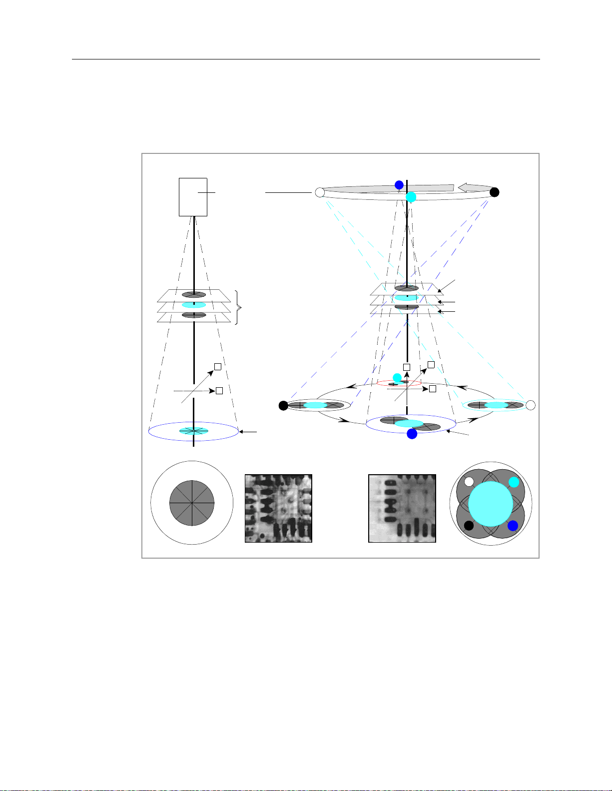
Figure 1-2 illustrates the X-ray geometry for Transmissive X-ray Imaging and X-
ray Laminography in a 3-dimensional imaging plane.
7UDQVPLVVLYH;UD\,PDJLQJ
X-RAY SOURCE
DEFECT
Y
X
3ODQHRI)RFXV
3
6WDWLRQDU\
6FLQWLOODWRU
;UD\/DPLQRJUDSK\
1
4
2
3
$ERYHWKH3ODQH
RI)RFXV
3ODQHRI)RFXV
%HORZWKH3ODQHRI
)RFXV
Y
Z
2
X
1
4
5RWDU\
6FLQWLOODWRU
7UDQVPLVVLYH;UD\,PDJLQJ
;UD\/DPLQRJUDSK\
1
680
',))
3 4
Figure 1-2: X-ray Laminogr aphy versus Transmissive X-ray Imaging
Agilent 5DX Service Guid e 1-5
2
Page 24
What is the 5DX Automated X-ray Inspection System? 5DX Series 3
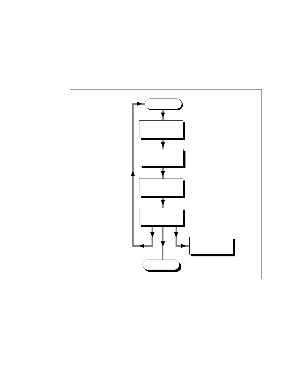
The 5DX System Process
Figure 1-3 is a flow chart illustrating the process that a panel goes through within
the 5DX System.
/RDG
)LUVWWLPH$OLJQ
6XUIDFH0DSDQG
&KHFN&$'
$XWR$OLJQ
6XUIDFH0DS
/RDGQH[WSDQHO
6HOHFWDQG7XQH
$OJRULWKPV
6HOHFWDQG5XQ7HVW
6HOHFW2XWSXWDQG
)RUPDW
8QORDG
(MHFWWHVWHGSDQHOWR
FRQYH\RUV\VWHP
Figure 1-3: Test Process Flow Chart
The PCA is loaded into the 5DX. For the 5DX to correctly test the solder joints,
the PCA has to be aligned. A surface map is made to compensate for variations in
the manufacturing process. The solder joints are measured and these
measurements are analyzed by the a lgorithms to determin e if they pass or fa il. The
algorithm thresholds, set up by the user will determine the pass or fail criteria. The
PCA is then unloaded from the 5DX.
1-6 Introduction and Overview
Page 25
5DX Series 3 5DX Overview
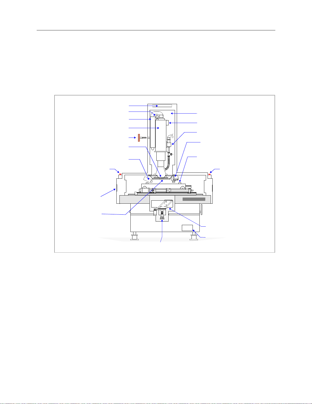
5DX Overview
The Main Cabinet (cutaway diagram shown in Figure 1-4), provides a shielded
housing and vibration resistant structure for the imaging and mechanical
assemblies of the 5DX System.
;UD\7RZHU&RROLQJ)DQ
3UHVVXUH*DXJH
,QWHJUDWHG+93RZHU6XSSO\
;UD\7XEH
;UD\7RZHU.H\
;UD\7XEH7DUJHW
3DQHO9LHZ&DPHUD
(PHUJHQF\6WRS
%XWWRQDQG;UD\
2Q,QGLFDWRU
2XWHU%DUULHU
,QQHU%DUULHU
;UD\,PDJH&DPHUD
GRANITE BASE
;UD\+LJK9ROWDJHN9GFIURPWKH
;UD\+LJK9ROWDJH3RZHU6XSSO\
;UD\7XEH'LHOHFWULF3UHVVXUH6HQVRU
,RQ3XPS
0DS3RLQW&DPHUDDQG/DVHU
;<=6WDJH$VVHPEO\
(PHUJHQF\6WRS
%XWWRQDQG;UD\
2Q,QGLFDWRU
5RWDU\6FLQWLOODWRU$VVHPEO\
9DF,RQ3XPS3RZHU6XSSO\
Figure 1-4: Agilent 5DX System Main Cabinet (I nternal Assembli es)
Agilent 5DX Service Guid e 1-7
Page 26

5DX Overview 5DX Series 3
Electronics Bay
The electronics bay, shown in the following figures, contains the 5DX System
control, communications and processing equipment.
Front View
The front view, shown in Figure 1-5 identifies the units housed within the
electronics bay. Note that in the figure below, the electronics bay is shown without
the front door.
System
Status
(contains
motion control
board #1 and
#2)
Motor Enable
Control
(inside front panel)
X, Y1, Y2, R
Servo Modules
(inside front panel)
X-ray Scan
Controller
Low Vol tage
Power
Supplies
System
Controller
PCI Expansion
Chassis
Digital I/O
Assembly
Motion Control
Assembly
Diagnostic
Access Panel
(inside front
panel)
Figure 1-5: 5DX Series 3 Elect ronics Bay (F ront V iew)
1-8 Introduction and Overview
Page 27
5DX Series 3 5DX Overview
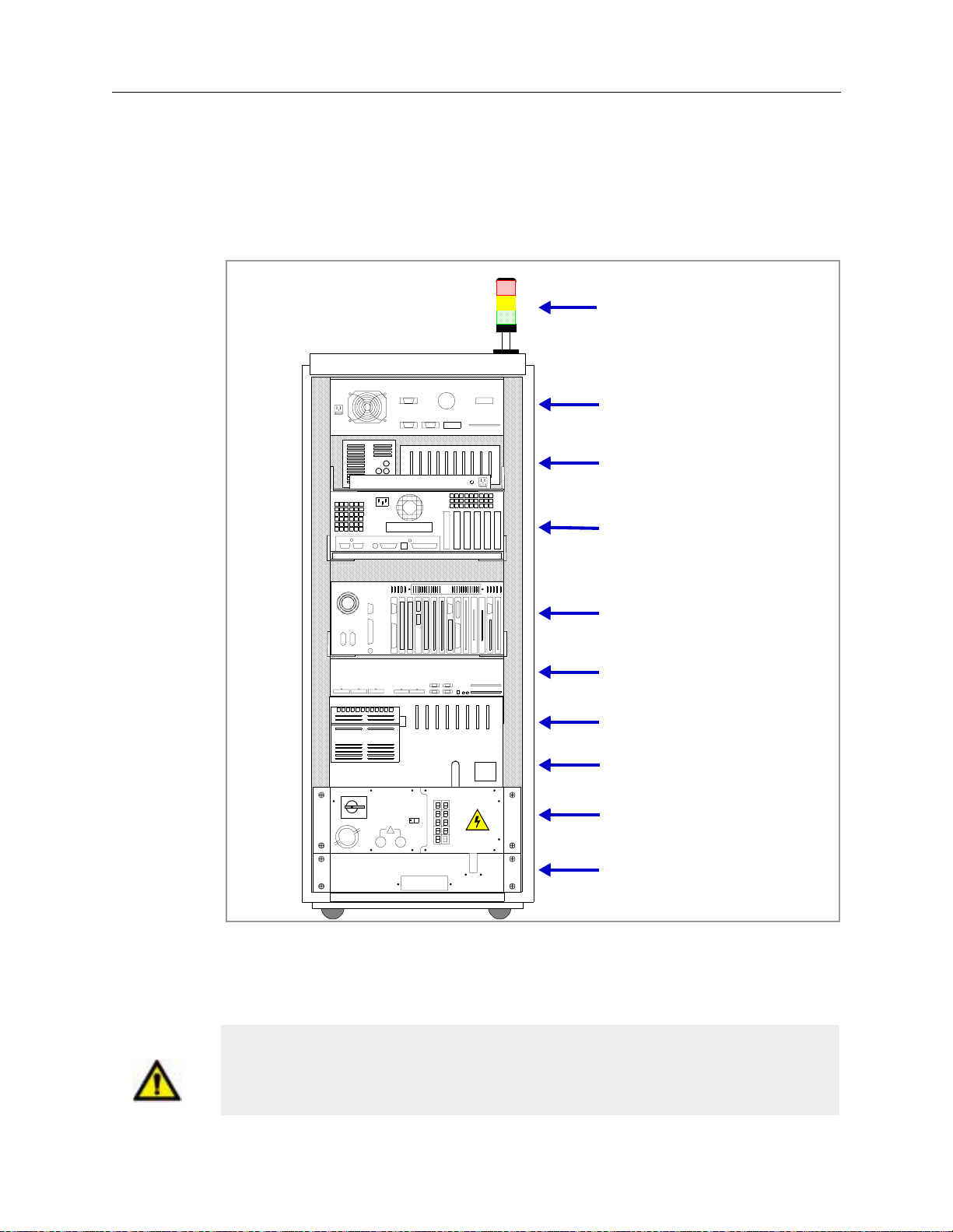
Rear View
The rear view (Figure 1-6) identifies units housed within the electronics bay
.
System Status Beacon
X-ray Scan
Controller
Low Vol tage Power
Supply Tray
System
Controller
Expansion
Chassis
Digital I/O
Laser Displacement Unit
Motion Control
Assembly
1
0
!
Power
Distribution Unit
Wire Egress
Figure 1-6: 5DX Series 3 Elect ronics Bay (Rea r V i ew)
.
Caution The ac accessory outlets are for Agilent Technologies installed accessories
ONLY. Plugging any other equipment into these accessory outlets may cause
damage to either the device or the 5DX.
Agilent 5DX Service Guid e 1-9
Page 28
5DX Overview 5DX Series 3
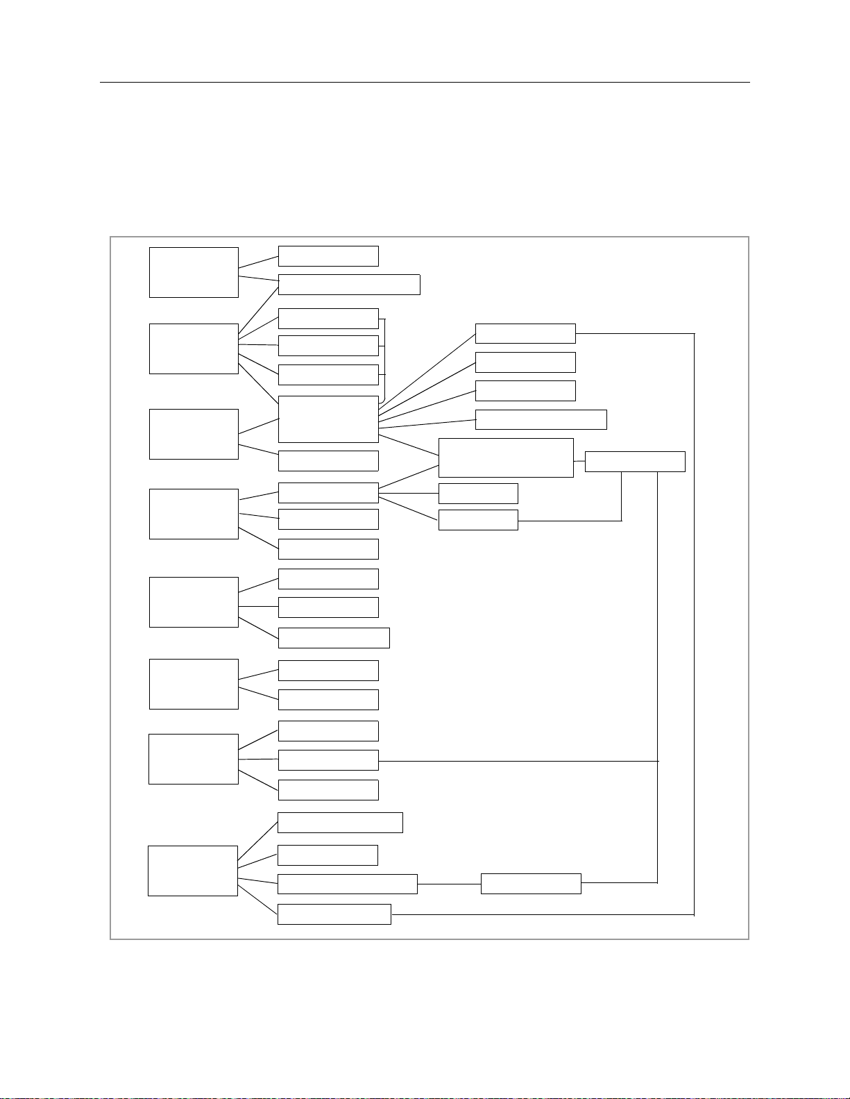
Subsystems of the Agilent 5DX System
The 5DX System consists of several subsystems. These subsystems provide the
overall system functions. A heirarchical diagram is shown in Figure 1-7.
X-ray Tube
HV/XRAY
SYSTEM
POWER
SYSTEM
CONTROL
HV Power Supply
PDU
LV Pwr Sply
Auxilliary PS
Electronics
Bay
Operator MWT
Controller
Expander
Digital I/O
X-ray Scan Cntrlr
Motion Control
Assembly
Servo Modules
PANEL
HANDLING
PNEUMATIC
INTERLOCKS
SURFACE
MAP
IMAGING
Stage
Barriers
Digital I/O
Barriers
Panel Clamps
Valves/Controls
Interlocks
Sensors
Lasers
Z motors
Laser Camera
X-ray Scan Cntrlr
Image Camera
Rotary Scintillator
Middle Rail
X/Y Motors
R motor
Frame Grabber
Figure 1-7: System Heirar chical Dia gram
1-10 Introduction and Overview
Page 29

5DX Series 3 5DX Overview
Safety Interlock Subsystem
The Safety Interlock Subsystem prevents the X-ray, Laser and Motion Driver
assemblies from operating in the event that any access panel is open. The Safety
Interlocks are used to prevent injury to personnel, the 5DX System and printed
circuit assemblies under test
127(
The X-ray Tube Dielectric Pressure Sensor is also connected to the
Safety Interlock Subsystem, and will automatically shut OFF power
to the X-rays if the vessel pressure fal ls below safe operating limits
(less than 2.8 kg/cm2 (40 psi)).
X-ray High Voltage Power Supply
The X-ray High Voltage Power Supply provides -160 kilovolts dc of conditioned
power required to operate the X-ray Tube. It also supplies +15 volts dc and -15
volts dc for the X-ray Tube Electronics. The X-ray HV Power Supply also
provides software controlled monitoring facilities, necessary to maintain a stable
X-ray source.
WARNING There are high voltages inside of the X-ray High Voltage Power Supply and
running through the High Voltage Cable. There are no User serviceable
parts inside of the X-ray High Voltage Power Supply. Do Not attempt to
open or otherwise service this item. Do Not remove the High Voltage Cable.
The X-ray High Voltage Power Supply produces -160 kilovolts dc of conditioned
power to drive the X-ray Tube, +15 volts dc and -15 volts dc for the X-ray tube
electronics. The X-ray High Voltage Power Supply is discussed in the power
subsystem chapter
Agilent 5DX Service Guid e 1-11
Page 30

5DX Overview 5DX Series 3
Panel Handling Subsystem
The Panel Handling Subsystem provides loading and unloading of printed circuit
assemblies (panels) for testing. The Panel Handling subsystem supports Surface
Mount Equipment Manufacturers Association (SMEMA) interface standards.
The Panel Handling Subsystem also positions the panel under test. This is done by
controlling the three mechanical motion axes (X, Y and Z) and the Autowidth
Adjust Motors. The X-Axis and Y-Axis are driven by servomotors, while the ZAxis is driven by four vertically positioned stepper motors. The rails in the XYZ
Stage Assembly are adjusted to the size of the panel by the autowidth adjust
motors.
Surface Map Subsystem
The Surface Map Subsystem maps the surface characteristics of each panel.
Components of the Surface Map Subsystem include the laser, the laser camera and
the surface mapping software. Surface measurement is required to facilitate the
accurate positioning of the Z-Axis in relationship to the Plane of Focus.
Imaging Subsystem
The Imaging Subsystem contains image acquisition hardware and software
necessary to generate slice image data. The process begins with the Electron Beam
and resultant Video images are digitized into 256 gray levels and analyzed.
Pneumatics Subsystem
The 5DX System contains several pneumatic assemblies. Pneumatics operate the
inner and outer barriers, the panel clamps on the XYZ Stage Assembly, and the
panel in place mechanical actuator.
System Controller and Expansion Chassis
Combined, the System Controller and Expansion Chassis provide the necessary
hardware I/O connections to operate the 5DX System. The System Controller
controls the 5DX System operations. Interaction is provided by the User Interface.
The System Controller contains the Frame Grabber PCA, the Transceiver PCA, the
floppy and hard disk drives, the DAT tape unit and the CD-ROM drive. The
Expansion Chassis contains a fourteen-slot backplane and is where the Motion
Control, Camera Control, Modem, Serial Port and Receiver PCAs reside.
1-12 Introduction and Overview
Page 31

5DX Series 3 5DX Overview
User Interface
The User Interface is a software environment used to provide menu-based access
to invoke programs which control system access, confirmation, diagnostic utilities,
programming and test operations. The User Interface will be covered in this guide
for the purpose of performing diagnostics only. See the 5DX User Guide for
additional information concerning the User Interface.
Operator Control
The Operator Control Console provides the user to machine interface that permits
operation of the 5DX System. The Operator Control Console provides key
operated system power, the power activation button for the X-ray Subsystem,
status indicators for monitoring the state of the safety interlocks and X-ray
emissions. The Operator Control Console is located on mobile workstation table.
Caution The System Controller slides out the left side of the Electronics Bay on a tray.
Do Not attempt to move the Electronics Bay while this tray is out.
Caution The Expansion Chassis slides out the front of the Electronics Bay on a tray.
Do Not attempt to move the Electronics Bay while this tray is out.
Caution The front panel of the Motion Controll Assembly opens on the front of the
Electronics Bay . Do Not attempt to move the Electronics Bay while this door
is open.
Agilent 5DX Service Guid e 1-13
Page 32

5DX Overview 5DX Series 3
1-14 Introduction and Overview
Page 33

2.Safety Summary
In this chapter...
This chapter describes the following topics:
n Safety Summary, 2-2
n Warnings, 2-3
n Emergency Stop, 2-4
n Emergency Procedures, 2-6
n X-ray Safety, 2-8
n X-ray Safety, 2-10
n High Voltage Safety, 2-11
n Laser Safety, 2-14
n Additional Information, 2-14
Agilent 5DX Service Guid e 2-1
Page 34

Safety Summary 5DX Series 3
Safety Summary
Prior to operating or performing maintenance activities on the Agilent 5DX
System, personnel should be aware of system safety precautions. The 5DX is
designed to be extremely safe, provided proper use and service precautions are
observed. All users should be aware of the following areas of safety:
• Emergency Stop — How to shut off the 5DX Main Cabinet in an emergency
situation.
• X-ray Safety — Effects of Radiation and the safeguards against exposure.
• High Voltage Safety — High Voltage and safe servicing practices.
• Mechanical Safety — Mechanical motion and safety precautions.
• Laser Safety — Laser optics and safety precautions.
The labels used on the equipment are shown in Figure 2-1.
,QYLVLEOHODVHUUDGLDWLRQFRQWDLQHG
ZKHQHQHUJL]HG'RQRWDWWHPSWWR
GHIHDWVDIHW\,QWHUORFNVP:QP
&ODVV,,,%/DVHU6XE6\VWHP&ODVV,
/DVHU3URGXFW
On the Operator Control Panel
WARNING or
Caution
Other 5DX Locations
Electrical Hazard
THIS EQUIPMENT
PRODUCES X-RAYS
Pinch Hazard
Figure 2-1: Labels Used on Equip ment
2-2 Safety Summary
Page 35

5DX Series 3 Warnings
Warnings
WARNING This product produces X-rays. Do not attempt to open any part of the
product. Do not operate this product or turn on the X-ray source unless all
shielding is in place. Operation without shielding in place can result in
exposure to X-rays. Exposure to X-rays can cause serious bodily injury.
Refer servicing to service-trained personnel.
WARNING This product produces High Voltage. Do not attempt to open any part of the
product. High Voltage can cause electrical shock resulting in serious bodily
injury. Refer servicing to service-trained personnel.
WARNING This product produces Laser Light Emissions. Do not attempt to open any
part of the product. Laser Light Emissions can cause serious eye injury.
Refer servicing to service-trained personnel
WARNING Do not, for ANY reason, attempt to defeat the built-in safety interlocks.
Operation without the Safety Interlock Subsystem functional can result in
exposure to X-rays, high voltage or laser light emissions. Exposure to Xrays can cause serious bodily injury. Contact with high voltage can cause
electrical shock resulting in serious bodily injury. Exposure to laser light
emissions can cause serious eye injury
WARNING Always DISCHARGE all high voltage connections prior to servicing
WARNING There is a service key that can be used to override motion control interlocks
for diagnostic purposes. NEVER place any body part (hand, arm, etc.) or
any other object inside the 5DX when this override is enabled.
This machine is classified as a Class I Laser Product containing a Class IIIB Laser
Subsystem, with an output of 780 nM <5 mW.
Use only QUALIFIED personnel to service this equipment.
Agilent 5DX Service Guid e 2-3
Page 36

Emergency Stop 5DX Series 3
Emergency Stop
Caution The Emergency Stop Buttons are intended for use in emergency situations only
and should not be used for normal system shutdown. Repeated misuse of the
Emergency Stop Buttons will eventually cause damage to certain components or
the loss of data or both.
127(
The AC “Mains” power disconnect is a circuit breaker i nstalled by the
end user and is to be located within 15 feet of the 5DX System
Power Distribution Unit (PDU). Local c odes and needs will def ine the
accessibility, configuration, and size of this disconnect. This
disconnect will disconnect all power to the 5DX System.
The Emergency Stop is used to quickly shutdown power to the 5DX Main Cabinet.
The Emergency Stop is intended for crisis situations only and should not be used
as the normal means to stop the 5DX.
The 5DX System is equipped with two Emergency Stop Buttons. The Emergency
Stop Buttons are located on either side of the 5DX System Main Cabinet, centered
above the outer barrier panels. Refer to Figure 2-2 for locations of the Emergency
Stop Buttons. Whenever one of the Emergency Stop Buttons is pressed, all power
is immediately removed from the 5DX subsystems, with the exception of the
System Controller and the monitor.
To restart the 5DX System after the Emergency Stop Button has been pushed
requires the Emergency Stop Release Key and the normal 5DX System startup
procedure, provided the condition which caused the operator to engage the
Emergency Stop Button is cleared.
2-4 Safety Summary
Page 37

5DX Series 3 Emergency Stop
Push down the Emergency Stop
Button, or toggle the AC “Mains”
Disconnect in an emergency
situation.
The Emergency Stop
Button locks OFF when
pushed.
View from the front of the 5DX System.
Figure 2-2: Emergency Stop Locations
5DX
6HULHV
Agilent 5DX Service Guid e 2-5
Page 38

Emergency Procedures 5DX Series 3
Emergency Procedures
In case of a disaster such as fire, explosion, flood, or strong earthquake, the X-ray
Tube must be de-energized immediately. In an emergency, de-energize the X-ray
Tube by one of the following methods:
• Turn the X-ray Control Key to the Off Position.
• Press the X-ray Control Off Button on the Operator Control Console as shown
in Figure 2-3 Location of X-ray Control Off Button (Series II).
• Press one of the Emergency Stop Buttons, refer to Figure 2-2.
• Open the AC “Mains” Disconnect circuit breaker supplying power to the 5DX
System.
Once de-energized, the X-ray Tube emits no radiation. After a disaster that may
have resulted in damage to the 5DX System shielding, an X-ray Safety Test of the
5DX must be performed prior to placing it back in operation. Consult the Agilent
Response Center before attempting to return the 5DX System to operation. An
electrical brownout or electrical power off, due to storms, does not constitute an
emergency since the system will simply shut itself off and may be restarted in the
normal manner after the power returns.
2-6 Safety Summary
Page 39

5DX Series 3 Emergency Procedures
X-ray Contro l
Off Button
Figure 2-3: Locati on of X-ray Contr ol Off Button
Agilent 5DX Service Guid e 2-7
Page 40

X-ray Safety 5DX Series 3
X-ray Safety
Effects of Radiation
There are a variety of natural and man-made emissions that are classified as
radiation. X-rays are included in most definitions. It should be noted that the
5DX System will not produce X-rays unless power is specifically provided to the
X-ray Tube, and will cease immediately upon removal of power. In addition, it
should be noted that the 5DX System is not designed to admit humans.
A complete description of the biological effects of radiation is outside the scope of
this guide, but is generally available at any library or local government office.
WARNING This product produces X-ray emissions. Do not attempt to open any part of
the product while X-rays are engaged. Do not attempt to defeat any of the
Safety Interlocks. Do not alter the shielding of the 5DX System. X-ray
emissions are dangerous and may cause side effects or even death if
encountered in large doses. Service must be performed by personnel
certified by Agilent.
X-ray Dose Limits
The State of California (see California Radiation Control Regulations, Title 17,
California Administrative Code, Section 30265), and other Agreement States, have
established maximum dose limits for individuals working in an area considered to
be uncontrolled (not under constant monitoring). These limits are the maximum
of no more than:
• 2 millirem / hour
• 100 millirem / 7 days
• 500 millirem / year
These limits were considered when the United States federal government
established the limit of 0.5 millirem/hour at 5 cm from the surface of any Cabinet
Radiography system. Agilent certifies that the 5DX System X-ray emissions are
less than the United States Government and International Safety Standards for
Cabinet X-ray Systems.
2-8 Safety Summary
Page 41

5DX Series 3 X-ray Safety
Definition of a Cabinet X-ray System
A Cabinet X-ray System is one that produces little or no X-ray exposure to the user
and is safe to operate and to be in close proximity to under foreseeable conditions.
The 5DX System is certified to produce not more than 0.5 millirem per hour at a
distance of 5 cm from the machine surface. Agilent warrants that the 5DX System
meets all Federal Regulations regarding a Cabinet Radiography Systems.
The 5DX System is classified as a “Cabinet X-Ray System” by the United States
Code of Federal Regulations: 21 CFR 1020.40 (X-Ray) and CFR 1040.10 (Laser).
The 5DX System is designed, manufactured and registered in accordance with
strict criteria established by the Department of Health and Human Services, Food
and Drug Administration, Center for Devices and Radiological Health (CDRH),
Department of Health and Human Services (DHHS), X-ray Products Branch.
Agilent certifies that the 5DX System X-ray emissions are less than United States
Government and International Safety Standards for a “Cabinet X-ray Systems.”
Built-In Safety Features
The 5DX System is enclosed in shielding that limits X-ray exposure to normal
background levels and all of the 5DX System access ports are safety interlocked to
prevent any accidental radiation exposure. In addition, Agilent performs an X-ray
Safety Test three times on every system prior to customer use:
1. At the completion of manufacture
2. Prior to shipment from Agilent’s facility, and
3. At the user’s facility.
Agilent further warrants and certifies that the 5DX System fully passes the
approved Certification Test for compliance with 21 CFR 1020.40 after shipping
and installation at the customer's facility.
Several 5DX Systems are currently in operation throughout the world. These
systems meet local and government X-ray exposure standards.
Registration Requirements
Customers are directed to check with their state radiation control program director
for registration requirements.
Agilent 5DX Service Guid e 2-9
Page 42

X-ray Safety 5DX Series 3
X-ray Safety
Each of the following steps must be followed for the safety of personnel and
responsible equipment handling:
X-ray Safety Precautions
• Do not attempt to defeat the Safety Interlocks. The Safety Interlocks are
designed to prevent operation of the 5DX System if the access panels are not in
place.
• Do not substitute any shielding panels.
• Do not drill or modify the shielding panels in ANY way.
• Do not place any strong magnets near the X-ray Tube. The X-ray Tube is
designed to have a scanned beam. The beam scanning coils are designed to
limit the deflection of the electron beam to the target area. Any magnets
stronger than 50 gauss placed immediately at the position of the deflection
coils could cause the electron beam to hit the side of the X-ray Tube. The entire
X-ray Tube is shielded in the 5DX System, so, no additional radiation will be
emitted from the system. However, proper operation of the machine would not
be possible in a strong magnetic field.
• Do not apply pressure to, modify or damage the X-ray vacuum window. The
X-ray vacuum window supports the tungsten target material. If the X-ray
vacuum window is broken, the X-ray Tube will cease to operate.
• Do not kink or sharply bend the High Voltage Cable, as it is used to supply a
ground and the high voltage to the X-ray Tube. Sharp bending tends to lower
the dielectric strength of the High Voltage Cable and may lead to failure of the
system. Since one ground is provided through the shielding of the High
Voltage Cable, the cable should be kept free of cracks in the insulation, kinks
or punctures.
• Do not operate the X-ray High Voltage Power Supply without the High
Voltage Cable connecting it to the X-ray Tube properly installed. The high
voltage connections are not user serviceable. Refer service to Agilent
personnel only.
• Do not insert any portion of the body into the XYZ Stage Assembly or the
Loader Assembly , as these contain moving mechanisms and harm may come to
the user, even though movable barriers are present.
2-10 Safety Summary
Page 43

5DX Series 3 High Voltage Safety
Safety Requirements
• Do consult the Agilent Response Center before attempting to service any
components of the X-ray Subsystem.
• Do properly follow ALL Warnings and Cautions.
• Do verify that the X-ray T ub e has an external green ground wire going directly
to the ground connection on the X-ray High Voltage Power Supply . This safety
ground is in addition to the ground supplied by the High Voltage Cable and the
X-ray Tube Mount.
High Voltage Safety
The 5DX System has no exposed high voltage potentials. High voltages are
contained within subsystems, and should only be accessed by Agilent personnel.
WARNING This product produces High Voltage potentials. Do not attempt to open any
part of the product. Contact with High Voltage can cause serious bodily
injury. Refer all servicing to service-trained personnel.
High Voltage Subsystem
127(
The High Voltage Subsystem’s high voltages are contained within the X-ray High
Voltage Power Supply, the High Voltage Power Supply Cable, and the X-ray Tube
Assembly . Under no conditions are the High Voltage Subsystems user serviceable.
The X-ray High Voltage Power Supply produces up to 160,000 volts direct current
(dc). Should any damage occur to any of the high voltage components, remove
power from the system, and contact the Agilent Response Center prior to
attempting any further operation of the 5DX System.
For support purposes, the following components make up the High
Vol tage Subsystem: X-ray Tube Assembly, X-ray High V oltage
Power Supply and the High Voltage Power Supply Cable.
Agilent 5DX Service Guid e 2-11
Page 44

High Voltage Safety 5DX Series 3
Power Distribution Unit (PDU)
The 5DX System is powered by line voltage alternating current (ac) of 200 to 415
volts, at 50 or 60 Hertz (cycles), three phase. Prior to distribution to the subsystem
modules, this supply voltage is transformed to the appropriate voltage levels for
the various components. The lines have thermal circuit breakers at both voltage
levels. This power distribution is engaged by the Emergency Stop Contactor,
which is controlled by 12 volts dc, and may be interrupted in an emergency by any
of the following:
• Pressing one of the Emergency Stop Buttons.
• Open the AC “Mains” Disconnect circuit breaker supplying power to the 5DX
System.
WARNING Do not disconnect any motor cables from the motor or servo module unless
you are certain the motor is not spinning. A spinning motor can generate
hazardous voltages. This is especially true for the Rotary Scintillator. Be
sure it stops spinning before disconnecting any cables.
Mechanical Safety
WARNING This product contains high speed motion components. The motion
components can cause severe bodily injury. Do not attempt to open any part
of this product while the motion components are operational. Do not
attempt to defeat the Safety Interlocks.
WARNING The Rotary Scintillator spins at 750 revolutions per minute. The rotation of
the Rotary Scintillator Assembly can cause sever bodily injury. The safety
interlocks do not stop the Rotary Scintillator. Remove power to the Motion
Driver Assembly and wait until the Rotary Scintillator Assembly stops
spinning before removing the clear plastic safety cover.
The motion mechanics of the 5DX System involve high speed mechanical
assemblies, including the panel conveyors and the XYZ Stage Assembly.
Mishandling could result in bodily injury. To help prevent any risk of injury, the
major motion components of the 5DX System are enabled through the Safety
Interlock Subsystem. If an access panel is open, or if an incorrect sensor state is
2-12 Safety Summary
Page 45

5DX Series 3 High Voltage Safety
sensed, the X-Axis, Y-Axis and X-ray Subsystem functions are ceased. There is an
override to this using a Service Key for diagnostic purposes.
WARNING There is a service key that can be used to override motion control interlocks
for diagnostic purposes. NEVER place any body part (hand, arm, etc.) or
any other object inside the 5DX when this override is enabled.
Agilent 5DX Service Guid e 2-13
Page 46

Laser Safety 5DX Series 3
Laser Safety
WARNING The 5DX System contains a class IIIB laser subsystem. The laser is capable
of causing optical (eye) damage. Do not attempt to defeat any Safety
Interlock. Do not attempt to operate the laser with the access panels open.
The 5DX System uses a solid-state laser to perform a Surface Map of the panel.
This laser has an output of less than 5 mW (milliwatt) at 780 nm (nanometers, or
10-9 meters). Because this laser is capable of causing optical (eye) damage, it is
rated as a class IIIB laser subsystem. The laser operation is linked to the Safety
Interlocks, such that it cannot operate with the access panels open. This effectively
renders the 5DX System a Class I laser product (inherently safe).
Additional Information
127(
127(
The recommendations presented are not intended to be used in lieu
of any government regulations of applicable jurisdiction, but, are
designed to serve only as a guide to basic safety and the operation
of the 5DX Structural Process Test System.
Replacement or repair of the X-ray Tube Assembly, the X-ray Image
Camera, or related system internal assemblies may be made only by
Agilent authorized personnel or individuals who have received
proper training and are certified by Agilent.
2-14 Safety Summary
Page 47

5DX Series 3 Additional Information
Agilent 5DX System Training
Agilent strongly recommends the “Agilent 5DX System Service Course” as a
prerequisite for maintaining optimal safety standards and performing system
servicing. The “Agilent 5DX System Service Course” and the “Agilent 5DX
System Operations Course” provide a qualified understanding of the Agilent 5DX
System safety, operations and maintenance.
For additional information, please call the Agilent Response Center.
Agilent 5DX Service Guid e 2-15
Page 48

Additional Information 5DX Series 3
2-16 Safety Summary
Page 49

3.Safety Interlock Subsystem
In this chapter...
This chapter describes the following topics:
n Overview, 3-2
n Safety Interlock Controller, 3-3
n Safety Interlocks, 3-6
n Safety Interlock Locations, 3-7
n Safety Interlock Switches, 3-8
n Safety Interlock Chains, 3-10
n Operator Control Console, 3-14
Agilent 5DX Service Guid e 3-1
Page 50

Overview 5DX Series 3
Overview
The Safety Interlock Subsystem provides the Agilent 5DX System with an
automated integral security system, designed to safeguard personnel from
accidental exposure to X-rays, laser light emissions and mechanical operations.
The Safety Interlock Subsystem is comprised of the following components:
• Safety Interlock Controller — Serves as the interface between the safety
interlocks, the X-ray High Voltage Power Controller, the Operator Control
Console, the Laser Enable circuit and the Motion Enable circuit.
• Safety Interlocks — Each safety interlock consists of at least one switch for
Chain 1 and one switch for Chain 2.
• Chain 1 — Provides the interlock control for the X-ray High Voltage Power
Controller, the enable for the Laser(s), and the enable for the Motion Drivers.
• Chain 2 — Provides the enable for the X-ray High Voltage Power Controller.
• X-ray Tube Dielectric Pressure Sensor — Detects low dielectric pressure (less
than 40psi) inside the X-ray Tube Pressure Vessel and is in series with C hai n 1.
• Operator Control Console — Controls the X-ray High Voltage Power
Controller and provides the indications for X-ray On and Interlocks
Closed/Laser On. The control console is located on the main cabinet on the
mobile workstation table.
• X-ray High Voltage Power Controller — Controls power and provides fault
protection for the electronic assemblies of the X-ray Tube.
3-2 Safety Interlock Subsystem
Page 51

5DX Series 3 Safety Interlock Controller
Safety Interlock Controller
The Safety Interlock Controller, (E7200-66538) is attached to the rear of the base
of the Main Cabinet as shown in Figure 3-1, and serves as the electrical interface
between the safety interlocks and the X-ray High Voltage Power Controller
(E7200-66226), the Operator Control Console, the Laser Enable circuit and the
Motion Enable circuit.
The E7200-66538 controller has a link to the safety valve.
+
1
1
(E7200-66538)
Figure 3-1: Safety I nter lock Controll er
The Safety Interlock Controller contains two sets of Light Emitting Diodes
(LEDs). There is a set for normal operation and a set for diagnostics.
Agilent 5DX Service Guid e 3-3
Page 52

Safety Interlock Controller 5DX Series 3
Normal Operation LEDs
• DC Power — When +12 volts dc is present, this green LED will be lit.
• Chain 1 — When the +12 volts dc safety interlocks on Chain 1 are closed, this
green LED is lit.
• Chain 2 — When the +24 volts dc safety interlocks on Chain 2 are closed, this
green LED is lit.
• Enable On — After the X-ray Control Key is turned to the Enable position, and
after the X-ray Control On Button has been depressed, this green LED will
light At this point all of the safety interlocks are closed and the X-ray High
Voltage Power Supply has both of its enables.
Diagnostic LEDs
The Diagnostic LEDs are used in finding an open safety interlock. This condition
is indicated by the unlit Interlocks Closed Laser On indicator.
To activate the diagnostic LEDs, the Service Switch needs to be put into the
Service position. When the Service Switch is set to the Service position, there is no
power to all of the other relays or the Operator Control Console. The Safety
Interlocks Closed Laser On indicator on the Operator Control Console will not
function at this time.
The appropriate LED(s) on the Safety Interlock Controller will light to indicate
that there is an open safety interlock in a particular loop.
• Chain 1, Main Cabinet — There is an open in the +12 volt dc circuit associated
with the Main Cabinet.
• Chain 2, Main Cabinet — There is an open in the +24 volt dc circuit associated
with the Main Cabinet.
• Chain 1, barrier — There is an open in the +12 volt dc circuit associated with
the left or right external barriers (doors) or the inner barrier (shutter).
• Chain 2, barrier — There is an open in the +24 volt dc circuit associated with
the left or right external barriers (doors) or the inner barrier (shutter).
3-4 Safety Interlock Subsystem
Page 53

5DX Series 3 Safety Interlock Controller
For troubleshooting purposes, there are two test points on the Safety Interlock
Controller. TP1 is for Chain 1 and TP2 is for Chain 2. Connect a voltmeter, set to
beep on a voltage level, from the appropriate test point to the test point’s ground. If
an audible voltmeter is unavailable, it will take two persons to troubleshoot the
interlocks, one to check and operate the interlocks and another to monitor voltage
levels.
Return the 5DX System to production
status by putting the Service Switch i n
the Normal position. The Normal
position is indicated by the white
rectangle on the silkscree n . The switch
in Figure 3-2 is shown in the Normal
position.
Normal
Position
Figure 3-2: Service Swit ch
Agilent 5DX Service Guid e 3-5
Page 54

Safety Interlocks 5DX S e ries 3
Watchdog Timer
127(
Included on the Safety Interlock Controller is a Watchdog Timer. The Watchdog
Timer’s purpose is to monitor a signal from the System Controller. Every 10
minutes, the System Controller sends a signal to the Watchdog Timer. If the
Watchdog Timer does not receive this signal, then X-rays are shut down.
There is a Watchdog Tripped LED on the Safety Interlock Controller. If the
W atchdog T i mer has timed out, meaning, it has been over 10 minutes since the last
signal from the System Controller, then this red LED will light.
Safety Interlocks
The Safety Interlocks are used on the access panels, inner, outer and movable
barriers. The safety interlocks disable the X-ray, Laser, and Motion Driver
components instantaneously when one of the following conditions occurs:
• if an access panel is opened,
This feature has not been implemented yet. There are two jumpers
on the Safety Interlock Controller. If either of these jumpers is cut,
then the Watchdog Timer may trip and shut down X-rays.
• if either right or left outer barrier and the inner barrier are open at the same
time,
• or if the X-ray T ube Dielectric Pressure falls below the operating specification
of 40 psi.
The status of the safety interlocks will be indicated on the Operator Control
Console and the Safety Interlock Controller. If all of the safety interlocks are
closed, then the Safety Interlocks Closed Laser On indicator will be lit. The Safety
Interlock Controller has two light emitting diodes (LEDs) that will be lit when the
safety interlock chains are closed. Refer to the section titled Safety Interlock
Controller for more information about the LED operation.
3-6 Safety Interlock Subsystem
Page 55

5DX Series 3 Safety Interlock Locations
Safety Interlock Locations
The safety interlocks are located in the following areas (refer to Figure 3-2 and
Figure 3-7 for locations):
• All 5DX System Main Cabinet access panels:
• Two sliding access panels located on the lop of the Main Cabinet
• Three sets of side access panels, one set on the front, one set on the
right side, and one set on the rear
• A top access panel above the right side access panels
• One X-ray Tube Tower access panel.
• The inner barrier under the X-ray tower
• The outer barrier(s).
X-ray Tube
Dielectric
Outer
Barriers
X-ray Tower
Access Panel
LEGEND
Side Access Panels
X-ray Tower Access Panel
X-ray Tube Dielectric Pressure
Sensor
Sliding Access Panels
Loader and Top Access Panels
Inner and Outer Barriers
Side Access Panel
Top
Access
Panel
Sliding
Access
Figure 3-3: Safety I nter lock Locati ons
Agilent 5DX Service Guid e 3-7
Page 56

Safety Interlock Switches 5DX Series 3
Safety Interlock Switches
There are different types of safety interlock switches within the 5DX System. The
type of switch used depends on the application. The sliding access panels use a
switch as shown in Figure 3-4. T o open a sliding access panel requires the use of a
key.
(Top Down View)
Jumpered Terminals
Contacts
(Contactor View)
Single Level Contactors
Adjustable Bulkhead
Fasteners
Safety Interlock
Chain Cable
Figure 3-4: Safety I nter lock Switch for th e Slid ing Access Panels
The side and top access panels use a switch as shown in Figure 3-5. T o open a side
or top access panel requires the use of a screwdriver.
Plunger
Busing Mount
BZ-2RQ1-A2
Mount Hole
Terminal
Connections
Figure 3-5: Safety I nterloc k Switch for th e Side and Top Access Panels
15AMP
3-8 Safety Interlock Subsystem
Page 57

5DX Series 3 Safety I nterlock Switches
The outer barrier frame assembly is shown in Figure 3-6.
(Front View)
Contacts Inside Main Cabinet
(Top Down View)
Frame Pins
Figure 3-6: Safety I nter lock Switch for th e Outer Barr ier Frame
The interlocks for the inner barrier (shutter) assembly are shown in Figure 3-7.
This is as viewed from the front of the 5DX. The pins are on the right barrier half
in each case and the contact blocks are on the left.
Contact Block
Pin Block
(Side View of Barrier halves)
Figure 3-7: Safety I nter lock Switch for th e Inner Barrier Fra me
Agilent 5DX Service Guid e 3-9
Page 58

Safety Interlock Chains 5DX Series 3
Safety Interlock Chains
The Safety Interlock switches on the Inner Barrier and the Outer Barrier are in
parallel. This allows either Outer Barrier to be open when the Inner Barrier is
closed, or to have the Inner Barrier open when the Outer Barriers are closed.
Figure 3-8 shows how the Safety Interlocks are wired.
Chain #1
12 Volts
Inner Barrier
Chain #2
24 Volts
Left Outer Barrier Right Outer Barrier
Inner Configuration - Panel Inspection
Chain #1
12 Volts
Inner Barrier
Chain #2
24 Volts
Left Outer Barrier Right Outer Barrier
Outer Configuration - Panel Load/Unload
Figure 3-8: Safety I nterloc k Wir ing Diagram
3-10 Safety Interlock Subsystem
Page 59

5DX Series 3 Safety Interlock Chains
Inner Barrier Safety Interlocks
There are two sets of Safety Interlocks on the Inner Barrier. Each set of Safety
Interlocks contains a Contact Block and a Pin Block, as shown in Figure 3-9. The
Contact Blocks are placed on the Left Half of the Inner Barrier. The Pin Blocks are
placed on the Right Half of the Inner Barrier.
The replacement part numbers for the Safety Interlocks are as follows:
• E7200-07952 — Pin Block - goes on the Right Half of the Inner Barrier.
• E7200-07953 — Contact Block - goes on the Left Half of the Inner Barrier.
Contact Block Pin Block
Figure 3-9: Inner Bar rie r’s Safety Interlock
Agilent 5DX Service Guid e 3-11
Page 60

Safety Interlock Chains 5DX Series 3
Outer Barrier Safety Interlocks
There are two different Safety Interlocks on the Outer Barrier. The locations of
the Safety Interlocks are shown in Figure 3-10.
The Primary Safety Interlock contains a Contact Block and a Pin Block, as
shown in Figure 3-11. The Secondary Safety Interlock contains a Plunger and
a Switch, as shown in Figure 3-12.
The replacement part numbers for the Safety Interlocks are as follows:
• 3101-3526 — Outer Barrier Primary Safety Interlock - contains both the
Contact Block and the Pin Block.
• 3101-2425 — Outer Barrier Secondary Safety Interlock - this is the Switch.
Secondary
Safety Interlock
Figure 3-10: Outer Barrier’s Saf ety I nterlock s
3-12 Safety Interlock Subsystem
Primary Safety
Interlock
Page 61

5DX Series 3 Safety Interlock Chains
Pin Block
Contact Block
Figure 3-1 1: Outer Barrier’s Primary Safe ty I nter lock
Plunger
Switch
Figure 3-12: Outer Barrier’s Secondar y Safet y Interl ock
Agilent 5DX Service Guid e 3-13
Page 62

Operator Control Console 5DX Series 3
Operator Control Console
The Operator Control Console provides the user to machine interface that permits
operation of the 5DX System. The Operator Control Console provides key control
of the hi voltage power supply. The buttons are for enabling or disabling the high
voltage power supply. The Operator Control Console has status indicators for
monitoring the state of the safety interlocks and X-ray emissions. The Operator
Control Console is located on the mobile workstation table.
Figure 3-13: Operator Control Console
3-14 Safety Interlock Subsystem
Front View
Page 63

5DX Series 3 Operator Control Console
The Operator Control Console has a variety of controls and indicators:
• X-ray Control Key — Provides the power to the Enable circuit.
• X-ray Control On Button — Enables power to the X-ray components.
• X-ray Control Off Button — Disables power to the X-ray components.
• X-ray On Indicator — A red indicator that indicates the current status of the
X-rays.
• Safety Interlocks Closed Laser On Indicator — A green indicator that
indicates the status of the Safety Interlock Subsystem’s low voltage control
loop. ON=ACTIVE and OFF = Access Panel Open, Fault condition or power
off.
Adjusting the Safety Interlocks on the Inner Barrier
Required Tools
• Ohmmeter with clip style test leads
• Gap Adjuster
• 7/64-inch hex wrench
• Ball Driver - 5/64-inch hex
• Cable Adapter (part of the Inner Barrier Adjustment Tool Kit, P/N E7200-
60053)
127(
For ease in performing this procedure, use the Stage Movement
Controls to move the XYZ S tage Assembly so it is centered in the X
direction and at the minimum Y position. The rails should be spaced
as far apart as possible.
Agilent 5DX Service Guid e 3-15
Page 64

Operator Control Console 5DX Series 3
Procedure
1. Select Utilities and press Enter.
2. Select Service and press Enter.
3. Select Panel Handling and press Enter.
4. Select Hardware Control and press Enter.
5. Press 0 (the letter) to put the Hardware Status and Control in Output Mode.
6. Type 09 to close the Inner Barrier.
7. Select System Access and press Enter.
8. Select Shutdown and press Enter.
9. Select Short Term Shutdown and press Enter.
10. Power off the Motion Driver Power Supply.
11. At the Safe ty Interlock Controller, unplug the cable connected to J25032. Plug
the loose end of the cable into the Cable Adapter.
12. Attach the test leads for the ohmmeter to 1 and 6 on the Cable Adapter.
13. Set the ohmmeter to the resistance mode.
14. Open the side access panel.
15. Inser t the 40 mil side of the Gap Adjuster between the two halves of the Inner
Barrier. To do this, gently pull back on the Inner Barrier half and place the 40
mil side of the Gap Adjuster against the Tungsten on the Inner Barrier half.
Guide the Inner Barrier half back into position. The force exerted by the Inner
Barrier halves will hold the Gap Adjuster in place.
3-16 Safety Interlock Subsystem
Page 65

5DX Series 3 Operator Control Console
16. Using a 7/64-inch hex wrench, loosen the two bracket screws on the Safety
Interlock Pin Block, as shown in Figure 3-14. This is on the Right Half of the
Inner Barrier.
Bracket Screws Worm Screw
Figure 3-14: Pin Block Screw Locati ons
17. Using the 7/64-inch hex wr ench positioned between the thumb a nd foref inger,
barely tighten the two bracket screws.
18. Use 5/64-inch hex wrench for the following:
a. Back out the W orm S crew until t he oh mme ter i ndica tes tha t t he t wo pie ces
of the Safety Interlock Switch are no longer making contact.
b. Turn the Worm Screw until it first makes contact.
c. Advance the Worm Screw an additional 1/4 turn more.
19. Tighten the two bracket screws.
20. Move the test leads for the ohmmeter to 2 and 5 on the Cable Adapter.
21. Repeat 16 through Ste p 19 for the Safety Interlock on the other side of the
Inner Barrier.
22. Inser t the 50 mil side of the Gap Adjuster between the two halves of the Inner
Barrier. To do this, gently pull back on the Inner Barrier half and remove the
Gap Adjuster. Place the 50 mil side of the Gap Adjuster against the Tungsten
on the Inner Barrier half. Guide the Inner Barrier half back into position. The
force exerted by the Inner Barrier halves will hold the Gap Adjuster in place.
23. At this point the ohmmeter should show an open condition.
24. Move the test leads for the ohmmeter to 1 and 6. Again, the ohmmeter should
show an open condition.
Agilent 5DX Service Guid e 3-17
Page 66

Operator Control Console 5DX Series 3
25. Remove the Gap Adjuster. To do this, gently pull back on the Inner Barrier half
and remove the Gap Adjuster. Guide the Inner Barrier half back into position.
26. Unplug the cable from the Cable Adapter.
27. Reinstall the cable in connector J25032.
28. Close all access panels.
Adjusting the Outer Barrier’s Primary Safety Interlock
Required Tools
• Primary Gap Adjuster (E7200-07966), shown in Figure 3-15
• Ohmmeter with clip style test leads
• T-10 Torx drive
Figure 3-15: Primary Gap Adjuster
3-18 Safety Interlock Subsystem
Page 67

5DX Series 3 Operator Control Console
w
Procedure
1. If the User Interface is running, select System Access and press Enter, then
select Quit from 5DX and press Enter.
2. Type ma and press Enter.
3. At the Master directory prompt, type shutdown and press Enter.
4. Type loadinit and press Enter.
5. Turn off the Motion Driver Power Supply.
WARNING Mechanical motion can cause severe injury. Turn off the Motion Driver
Power Supply to prevent movement of the XYZ Stage Assembly during this
procedure.
6. Disconnect the input line for the 5DX System main air.
7. Open both sliding access panels.
8. Attach the test leads for the ohmmeter to the test points on the Primary Safety
Interlock Contact Block as shown in Figure 3-16.
T-10 Torx Scre
Pin Block
Contact Block
Test Points
Figure 3-16: Primary Safety I nter lock
Agilent 5DX Service Guid e 3-19
Page 68

Operator Control Console 5DX Series 3
9. Set the ohmmeter to the resistance mode.
10. Using a T-10 Torx driver, loosen the two screws indicated in Figure 3-14
holding the Pin Block.
127(
The positioning of the Primary Gap Adjuster is very important. If the
Primary Gap Adjuster is positioned under the black, leading edge of
the Pin Block, then the Primary Safety Interlock will not be properly
set.
11. Inser t the lower side of the Primary Gap Adjuster between the Pin Block and
the Contact Block as shown in Figure 3-17. To do this, push up on the Pin
Block and insert the Primary Gap Adjuster between the Pin Block and the
Contact Block with the fingers pointing toward the Outer Barrier shielding.
Make sure that the Pin Block Bracket sits on the Primary Gap Adjuster and not
the black portion of the Pin Block
3-20 Safety Interlock Subsystem
Page 69

5DX Series 3 Operator Control Console
.
Pin Block Bracket
Pin Block
Contact Block
Primary Gap Adjuster
Pin Block Bracket
Primary Gap Adjuster
Figure 3-17: Placement of Primary Gap Adjuster
12. Push down on the Pin Block.
13. Verify that the Outer Barrier is in the closed position and that the ohmmeter
indicates zero resistance.
14. Using a T-10 Torx driver, tighten the two screws holding the Pin Block.
Agilent 5DX Service Guid e 3-21
Page 70

Operator Control Console 5DX Series 3
15. Inser t the higher side of the Primary Gap Adjuster between the Pin Block and
the Contact Block as shown in Figure 3-17. To do this, lift up on the Outer
Barrier using the opposite side slide and insert the Primary Gap Adjuster
between the Pin Block and the Contact Block with the fingers pointing toward
the Outer Barrier shielding. Make sure that the Pin Block sits on the Primary
Gap Adjuster and not the black portion of the Pin Block.
127(
With the Primary Gap Adjuster posit ioned pr operly, the Outer Barrier
will not be completey closed.
16. Verify that the Outer Barrier is in the down position and that the ohmmeter
indicates an open condition.
17. Remove the Primary Gap Adjuster.
18. Disconnec t the test leads of the ohmmeter from the Primary Safety Interlock
Contact Block.
19. Close all sliding access panels.
20. Reconnect the 5DX System’s main air input line.
21. Restart the User Interface and run Startup. Turn on the Motion Driver Power
Supply when instructed to do so.
3-22 Safety Interlock Subsystem
Page 71

5DX Series 3 Operator Control Console
Adjusting the Outer Barrier’s Secondary Safety Interlock
Required Tools
• Secondary Gap Adjuster (E7200-07967), shown in Figure 3-18
• 9/16-inch open-end wrench
• T-10 Torx driver
• Ohmmeter with clip style test leads
ButtonLower Slot Higher Slot
Figure 3-18: Secondary Gap Adjuster
Agilent 5DX Service Guid e 3-23
Page 72

Operator Control Console 5DX Series 3
Procedure
127(
It is possible to do this procedure with the Switch in the system.
However , it is easiest to set the gap for the Switch when holding the
Switch in your hand.
1. If the User Interface is running, select System Access and press Enter, then
select Quit from 5DX and press Enter.
2. Type ma and press Enter.
3. At the Master directory prompt, type shutdown and press Enter.
4. Type loadinit and press Enter.
5. Turn off the Motion Driver Power Supply.
WARNING Mechanical motion can cause severe injury. Turn off the Motion Driver
Power Supply to prevent movement of the XYZ Stage Assembly during this
procedure
6. Disconnect the input line for the 5DX System main air.
7. Open both sliding access panels.
8. Using a 5/64-inch hex wrench, remove the two screws holding the Switch, as
shown in Figure 3-19. Retain the screws for later use.
3-24 Safety Interlock Subsystem
Page 73

5DX Series 3 Operator Control Console
9. Using a 9/16-inch open-end wrench, loosen the nut on the Switch of the
Secondary Safety Interlock as shown in Figure 3-19.
Screws
Plunger
Shroud
T-10 Torx
Screws to
Nut to loosen
remove
Switch
Test Points
Figure 3-19: Secondary Safe ty Inter lock
10. Attach the test leads of the ohmmeter to the test points on the Switch as shown
in Figure 3-19.
11. Set the ohmmeter to the resistance mode.
Agilent 5DX Service Guid e 3-25
Page 74

Operator Control Console 5DX Series 3
12. Inser t the button of the Secondary Gap Adjuster into the end of the shroud as
shown in Figure 3-20. Refer to Figure 3-18 for identification of the button.
Figure 3-20: Secondary Gap Adjuster Pl acement fo r Sett ing Shroud
Position
13. If the ohmmeter shows an open condition, go to 14. If the ohmmeter is showing
zero resistance, turn the shroud until the ohmmeter shows an open condition.
14. Turn the shroud back and forth until you find the point where the Switch just
makes contact. At this point the ohmmeter should show zero resistance. Hold
the shroud in this position and at the same time, using a 9/16-inch open-end
wrench tighten the nut.
15. If you removed the Switch, reinstall it using a T-10 Torx driver and the two
screws removed in 8
16. Using a T-10 Torx driver, loosen the two screws on the Plunger , refer to Figure
3-19.
17. Insert the lower slot of the Secondary Gap Adjuster between the Switch and the
Plunger. To do this, push up on the Outer Barrier and insert the Secondary Gap
Adjuster between the Switch and the Plunger. The open end of the Secondary
Gap Adjuster fits around the Plunger. Allow the Outer Barrier to close.
3-26 Safety Interlock Subsystem
Page 75

5DX Series 3 Operator Control Console
18. Push the Plunger so it is flush with the Secondary Gap Adjuster as shown in
Figure 3-21.
Figure 3-21: Secondary Gap Adjuster Pl acement Usin g Lower Slot
19. Verify that the ohmmeter reads zero resistance.
20. Using a T-10 Torx driver, tighten the two screws on the Plunger.
21. Inser t the higher slot of the Secondary Gap Adjuster between the Switch and
the Plunger as shown in Figure 3-22. To do this, push up on the Outer Barrier
and insert the Secondary Gap Adjuster between the Switch and the Plunger.
Agilent 5DX Service Guid e 3-27
Page 76

Operator Control Console 5DX Series 3
The open end of the Secondary Gap Adjuster fits around the Plunger. Allow
the Outer Barrier to close.
Figure 3-22: Secondary Gap Adjuster Pl acement Usin g Higher Slot
22. Verify that the ohmmeter reads an open condition.
3-28 Safety Interlock Subsystem
Page 77

4.Power Subsystem
In this chapter...
This chapter describes the following topics:
n Overview, 4-2
n Power Distribution Unit, 4-4
n Wiring Diagrams, 4-9
n Low Voltage Assembly, 4-15
n Focus Coil Power Supply, 4-15
n Camera Power Supply, 4-17
n VacIon Pump Power Supply, 4-17
n X-ray High Voltage Power Supply, 4-18
n Emergency Stop Buttons and X-Ray Indicators, 4-20
n Long Term Shutdown For the Agilent 5DX System, 4-22
n Startup Procedure For the Agilent 5DX System, 4-24
Agilent 5DX Service Guid e 4-1
Page 78

Overview 5DX Series 3
Overview
The Power Subsyste m supplies all of the operating voltages to the various parts of
the Agilent 5DX System. The power subsystem, shown in Figure 4-1, provides ac
and dc power to the 5DX System.
$&
³0DLQV´
3'8
%UHDNHU
3'8
&RQWDFWV
&RQWURO
9ROWV$&
XQVZLWFKHGRXWOHWV
9ROWV$&
XQVZLWFKHGRXWOHWV
/DVHU3RZHU
/DVHU3RZHU
6\VWHP&RQWUROOHU
([SDQVLRQ&KDVVLV
/DQ+XE$&DGDSWHU
0RELOH:RUNVWDWLRQ
7DEOH0RQLWRUDQG
6SHDNHUV
/HIWDQG5LJKW
(PHUJHQF\6WRS
%XWWRQV
8QVZLWFKHG3RZHU
6ZLWFKHG3RZHU3'8UHDU
6ZLWFKHG3RZHU2XWOHW%R[
;5D\6FDQ
&RQWUROOHU
;0RWRU6HUYR
0RGXOH
50RWRU6HUYR
0RGXOH
<0RWRU6HUYR
0RGXOH
<0RWRU6HUYR
0RGXOH
9ROW$&
6ZLWFKHG2XWOHW
9ROW$&
6ZLWFKHG2XWOHW
%R[
9DF,RQ3XPS3RZHU
6XSSO\
+LJK9ROWDJH3RZHU
6XSSO\
&DPHUD3RZHU6XSSO\
;UD\7RZHU)DQ
;5D\6FDQ&RQWUROOHU
)RFXV&RLO3RZHU
6XSSO\
(OHFWURQLFV%D\)DQV
/RZ9ROWDJH3RZHU
6XSSO\
Figure 4-1: 5DX Power Subsystem
4-2 Power Subsystem
Page 79

5DX Series 3 Overview
The Power Subsystem includes the following components:
• Power Distribution Unit — provides switched and unswitched ac power to the
5DX System.
• Low Voltage Power Supply — provides dc power to the Digital I/O Assembly
and Chain 1 of the Safety Interlock Subsystem. (12, 24 and 48 volts dc)
• Focus Coil Power Supply — provides dc power to the Focus Coil of the X-ray
Tube Assembly.
• VacIon Pump Power Supply — provides power to the VacIon Pump.
• Camera Power Supply — provides dc power to the X-ray Image Camera.
• X-ray High Voltage Power Supply — provides -160 kilovolts dc power to the
X-ray Tube for generation of the electron beam.
The Emergency Stop Buttons shut down all switched power in the 5DX System.
The following procedures involve many of the Power Subsystem components, and
are also included in this chapter:
• Long Term Shutdown For the Agilent 5DX System on page 4-22
• Recover From an Emergency Stop on page 4-28
• Startup Procedure For the Agilent 5DX System on page 4-24
Agilent 5DX Service Guid e 4-3
Page 80

Power Distribution Unit 5DX Series 3
Power Distribution Unit
The Power Distribution Unit (PDU) receives AC “Mains” Power and distributes it
to the 5DX System. The PDU adjusts factory power to meet the 5DX System
operating voltage requirements. The PDU has a power switch used to remove all
switched system power and it is located at the rear of the Electronics Bay as shown
by the cutaway view in Figure 4-2.
127(
The cutaway view of
the Electronics Bay is
shown without the rear
door.
(Detail of the bottom
portion is all that is
shown here.)
1
0
E1135C
!
1
0
!
MAINS
01
!
CB2
CB4
CB6
CB8
CB10 CB9
Areas enlarged to
show detail.
(Main disable can be
locked in the “0”
position.)
!
0
1
ON
OFF
CB1
CB3
CB5
CB7
Power Distribution Unit
Figure 4-2: Power Distr ibution Unit (E1135C) Power Switch Location
The E1135C PDU also has a “lock out / tag out” (area of detail on the left) feature
so the PDU main can be locked in the off position. The hole for the lock will
accept a locking mechanism with a .62 cm (.25 in.) shaft (or smaller).
4-4 Power Subsystem
Page 81

5DX Series 3 Power Distribution Unit
A brief discussion of the PDU and how it relates to the 5DX System is provided.
For additional information on the E1135C Power Distribution Unit, refer to the
manual for it (E1135-90001).
Input Specifications
The Power Distribution Unit (PDU) is designed to accept world wide input power .
The power options available for the 5DX System are shown in Table 4-1 and
Table 4-2 on page 4-11.
Switched Output Terminals
Switched power is provided at the PDU output connector block and supplied to the
5DX System. All equipment connected to the switched outputs is controlled with
the PDU On/Off Switch located on the front of the PDU at the rear of the
Electronics Bay as shown in Figure 4-2.
The switched outputs are connected to eight auxiliary outlets at the rear of the
PDU as shown in Figure 4-3 for the E1135C. A switched output is also to the
cable coming from the front right wire egress on the front of the PDU. The
auxiliary outlets are numbered. The following components pug into the respective
auxiliary outlet as follows:
• Outlet 1 — Laser Displacement Sensor #2 (optional for 2nd laser, rear)
• Outlet 2 — Laser Displacement Sensor #1
• Outlet 3 —
• Outlet 4 —
• Outlet 5 — X motor Servo Module
• Outlet 6 — R motor Servo Module
• Outlet 7 — Y1 motor Servo Module
• Outlet 8 — Y2 motor Servo Module
Note that 220 volts ac goes directly to the Servo Modules. The modules are
interchangeable (except for software loaded on them) and have a fuse within the
AC receptacle.
Agilent 5DX Service Guid e 4-5
Page 82

Power Distribution Unit 5DX Series 3
The cable coming from the front right wire egress on the front of the PDU is
connected to the 220 volts ac switched outlets in the Main Cabinet. This provides
power for the X-ray Tower Fan, the VacIon Pump Power Supply, and the High
Voltage Power Supply.
!
!
50 Hz 60 Hz
100V 208V
120V 220V
127V 230V
200V 240V
Figure 4-3: Auxili ary Outlets at the Rear of the E113 5C PDU
Unswitched Output Terminals
Unswitched power is energized when the 5DX System is connected to AC
“Mains” Power . This unswitched power is only removed if t he AC “Mains” Pow er
is switched off, not when the PDU On/Off Switch is turned off. With the E1135C
PDU all power is removed if the main breaker (“lock out/tag out”) switch is set to
the “0” or off p osition. The unswitched output t erminals are connected to the cable
coming from the front left wire egress on the front of the PDU. This provides
power for the Monitor, and Speakers. A second outlet provides power to the
Expansion Chassis, and subsequently the System Controller.
Controls and Indicators
• The green rocker switch illuminates to indicates when power is turned on.
• The green light emitting diode (LED) illuminates when the switched outputs
are on.
• The yellow LED illuminates when the Emergency Stop loop has been opened,
or when there has been either a High Line or Low Line error.
4-6 Power Subsystem
Page 83

5DX Series 3 Power Distribution Unit
High/Low Line Monitoring/Protection
The PDU monitors the AC “Mains” Power input voltage at initial turn-on and
during normal operation. The PDU provides High Line and Low Line protection.
The High Line Circuit is intended to guard against initial installation mis-wiring.
For example, if the system was ordered as a 208 volts ac input power option and
connected to 380 volts ac input, the PDU will not turn on. All of the switched
power equipment will be protected since the PDU will not turn on. However, any
equipment connected to the unswitched power will most likely blow fuses or be
subject to other damage as the unswitched power is unprotected.
The Low Line Circuit is intended to protect against line sags and line interrupts. If
the voltage falls below a specified limit, for greater than one cycle, the switched
outputs of the PDU will turn off. The PDU must be reset once the line has been
restored. Reset the PDU by turning the On/Off Switch off, wait for at least 15
seconds and then turn the PDU back on again. If the AC “Mains” Power line is
stable, the PDU will remain up and running, if the AC “Mains” Power line is
unstable then the PDU may shut off again. The intent of the Low Line Circuit is t o
protect the 5DX System from damage since a low line drop-out may cause the
control circuitry of the 5DX System to lose data and communication with the XYZ
Stage Assembly.
If the AC “Mains” Power goes out for a period of time greater than 10 seconds, the
5DX System will turn on by itself when AC “Mains” Power is restored; however,
the Motion Driver Power Supply will not come on. This is to prevent the XYZ
Stage Assembly from moving until control has been re-established. The Motion
Driver Power Supply will need to be reset.
Emergency Shutdown
The PDU will not turn on unless the Emergency St op loop is connected. Any break
in the Emergency Stop loop will cause the switched outlets of the PDU to turn of f.
The PDU’s switched outputs can be turned of f by depressing one of the Emergency
Stop Buttons. This will open the contact disconnecting all power connected to the
switched outputs. Unswitched output power will remain on.
Agilent 5DX Service Guid e 4-7
Page 84

Power Distribution Unit 5DX Series 3
PDU Circuit Breakers and Fuses
WARNING High voltages present inside of the Power Distribution Unit. All four of the
fused terminals have line voltage present whenever the AC “Mains” Power
external circuit breaker is on, even if the PDU is turned off.
Caution Use care when replacing the Power Distribution Unit fuses. The threads are fine
and can be easily cross threaded.
Caution When replacing these fuses use only the same type fuses with the same current
rating.
The PDU input terminal block has fused terminals. There are two input terminals
fused at 0.5 amperes at 250 volts ac that provide protection and power to the
control circuitry of the PDU. There are two additional input terminals fused at 10
amperes at 250 volts ac that provide protection and unswitched power to the 5DX
System.
Caution The circuit breakers are not switches. Any attempt to force open the circuit
breakers will result in permanent damage to the circuit breaker.
The PDU has ten resetable 15 ampere thermal circuit breakers located on the front
of the PDU that provide protection to the switched outputs. If an overload should
occur the circuit breaker button extends and a white bar is visible indicating that
the circuit breaker has tripped.
4-8 Power Subsystem
Page 85

5DX Series 3 Wiring Diagrams
Wiring Diagrams
Figure 4-4 shows how the ac power is distributed from the E1135C PDU to the
components in the Electronics Bay.
9ROWV$&
(OHFWURQLFV%D\)DQV
6ZLWFKHG2XWOHW
3'8VLGH
/RZ9ROWDJH3RZHU6XSSO\7UD\
)RFXV&RLO
3RZHU6XSSO\
;UD\6FDQ&RQWUROOHU
9'& 9'
6\VWHP&RQWUROOHU
([SDQVLRQ&KDVVLV
'LJLWDO,2
0RWLRQ&RQWURO$VVHPEO\
6HUYR0RGXOH
/RZ9ROWDJH
3RZHU6XSSO\
6HUYR0RGXOH
6HUYR0RGXOH
!
3'8VLGH
!
/$1+XE$&
DGDSWHU
9ROWV$&
8QVZLWFKHG2XWOHW
/DVHU'LVSODFHPHQW
6HQVRUV
/DVHU
6HUYR0RGXOH
%DFNRI3'8
6ZLWFKHG
2SWLRQDO
/DVHU
9$&
&RQQHFWLRQVIRU
WKH(PHUJHQF\
6WRS%XWWRQV
7KLVILJXUHVKRZVUHODWLYHSRVLWLRQLQJRIWKH
FRPSRQHQWVZLWKLQWKH(OHFWURQLFV%D\
IURQWYLHZ
Figure 4-4: Electr onic s Bay AC Power Diagram (E1135C)
Agilent 5DX Service Guid e 4-9
Page 86

Wiring Diagrams 5DX Series 3
Figure 4-5 shows how the ac power is distributed from the PDU to the
components in the Main Cabinet.
9ROWV$&
6ZLWFKHG
2XWOHWV
&RPSRQHQWVDWWKHEDFNRIWKH
(OHFWURQLFV%D\
;UD\+LJK9ROWDJH
)URQWRI3'8
9$&6ZLWFKHG
;UD\
7RZHU)DQ
9DF,RQ3XPS
3RZHU6XSSO\
3RZHU6XSSO\
3'8VLGH
3'8VLGH
!
&RQQHFWLRQVIRU
!
WKH(PHUJHQF\
6WRS%XWWRQV
*URXQG/XJ
Figure 4-5: Main Cabinet AC Power Diagram
Figure 4-6 shows how the ac power is distributed from the PDU to the
components on the operator’s Mobile Workstation Table.
9ROWV$&
8QVZLWFKHG
2XWOHWV
0RQLWRU
3RZHU
6XSSO\
)URQWRI3'8
9$&6ZLWFKHG
&RPSRQHQWVDWWKHEDFNRIWKH
(OHFWURQLFV%D\
6SHDNHU
6SHDNHU
Figure 4-6: Mobile W or kstation T abl e AC Power Diagram
4-10 Power Subsystem
Page 87

5DX Series 3 Wiring Diagrams
Table 4-1: Power Options for 3 Phase Wye or Delta (no neutral)
POWER
OPTION
0ED 200 19 3 check country code
0EF 208 19 3 check country code
05D 220 19 3 check country code
05C 220 19 3 check country code
05H 230 19 3 check country code
0E6 240 19 3 check country code
Table 4-2: Power Options for 3 Phase Wye (with neutral)
POWER
OPTION
0E5 220/308 10 3 50
05L 230/400 10 3 50
Volts AC FLA Phase Freq.
Volts AC FLA Phase Freq.
0E7 240/415 10 3 50
Figure 4-7 shows the wiring input to the E1135C PDU and the outlet wiring for
the mobile workstation table and the expansion chassis.
Agilent 5DX Service Guid e 4-11
Page 88

Wiring Diagrams 5DX Series 3
.
(
0RQLWRUDQG
VSHDNHUV
([SDQVLRQ
&KDVVLV
$&0DLQV
G
L1
T1
L2 L3
1
0
N
Neutral Reference
LL1 LL2 NEU G
T2 T3
N
10A 10A
Figure 4-7: Input and Ext ernal Unswit ched Output Wirin g for the PDU
4-12 Power Subsystem
Page 89

5DX Series 3 Wiring Diagrams
PDU Wiring for the two power options is shown in Figure 4-8 and .
1
3
&%
&%
&%
&%
&%
&%
&%
&%
&%
&%
4
5
6
7
8
9
10
11
12
13
14
16
9ROWV$&6ZLWFKHG
2XWOHWVLQWKH(OHFWURQLFV
%D\IRU
)RFXV&RLO3RZHU6XSSO\
/RZ9ROWDJH3RZHU6XSSO\
'LJLWDO,2DQG(%D\IDQV
NEU
NEU
01
01
01
01
02
02
02
03
03
03
NEU
NEU
*51<(/
*51<(/
*51<(/
%51
%51
%51
%51
%51
%/8(
%/8(
%51
%/8(
%/8(
%/8(
*51<(/
*51<(/
*51<(/
0DLQ&DELQHW*1'
3'82XWOHWV
15
2
3
6
7
84
9ROWV$&6ZLWFKHG
2XWOHWVLQWKH0DLQ&DELQHW
;UD\7RZHU)DQ9DF,RQ
3XPS3RZHU6XSSO\DQG
+LJK9ROWDJH3RZHU6XSSO\
IRU
Figure 4-8: PDU Wiri ng for Options 0ED, 0EF, 05D, 05C, 05H and 0E6
Agilent 5DX Service Guid e 4-13
Page 90

Wiring Diagrams 5DX Series 3
1
3
&%
&%
&%
&%
&%
&%
&%
&%
&%
&%
4
5
6
7
8
9
10
11
12
13
14
16
9ROWV$&6ZLWFKHG
2XWOHWVLQWKH(OHFWURQLFV
%D\IRU
)RFXV&RLO3RZHU6XSSO\
/RZ9ROWDJH3RZHU6XSSO\
'LJLWDO,2DQG(%D\IDQV
NEU
NEU
01
01
01
01
02
02
02
03
03
03
NEU
NEU
*51<(/
*51<(/
*51<(/
%/8(
%/8(
%51
%51
%51
%51
%51
%51
%/8(
%/8(
*51<(/
*51<(/
0DLQ&DELQHW*1'
3'82XWOHWV
15
2
3
6
7
84
9ROWV$&6ZLWFKHG
2XWOHWVLQWKH0DLQ&DELQHW
;UD\7RZHU)DQ9DF,RQ
3XPS3RZHU6XSSO\DQG
+LJK9ROWDJH3RZHU6XSSO\
IRU
Figure 4-9: PDU Wiri ng for Options 0E5, 05L and 0E7
4-14 Power Subsystem
Page 91

5DX Series 3 Low Voltage Assembly
Low Voltage Assembly
The Low Voltage Power Supply assembly contains three power supplies, +12 volts
dc, +24 volts dc and +48 volts dc. The Low Voltage Power Supply assembly is an
integrated Power One power supply and has no external fuses and no user
serviceable parts. If it fails, the whole supply needs to be replaced.
+12 Volts DC Power Supply
The +12 volt dc power supply is rated at 20 amperes maximum. This power supply
provides dc power to the Digital I/O Assembly and provides the +12 volts dc for
Chain 1 of the Safety Interlock Subsystem. It also supplies 12 volts dc to the
Motion Control Assembly.
+24 Volts DC Power Supply
The +24 volt dc power supply is rated at 29 amperes maximum and is fused
with a 3 ampere fuse. This power supply provides dc power to the Digital I/O
Assembly.
+48 Volts DC Power Supply
The +48 volt dc power supply is rated at 12.5 amperes maximum. This power
supply provides dc power to the motion control assembly.
Focus Coil Power Supply
The Focus Coil Power Supply is an Agilent E3615. This power supply is capable
of delivering +20 volts dc at 3 amperes maximum. The Focus Coil Power Supply
is used in a constant current mode to power the Focus Coils in the X-ray Tube
Assembly.
Agilent 5DX Service Guid e 4-15
Page 92

Focus Coil Power Supply 5DX Series 3
3RZHU
&RUG
Power One Power
Supply (N7200-66220)
L
N
G
Focus Coil Power
Supply (T3615A)
These two power supplies are on the Low Voltage Power Supply Tray. Wiring
information for both is on a label affixed to the rear of the tray.
4-16 Power Subsystem
Page 93

5DX Series 3 VacIon Pump Power Supply
VacIon Pump Power Supply
WARNING There are high voltages inside of the VacIon Pump Power Supply and
running through the cable. There are no User serviceable parts inside of the
VacIon Pump Power Supply. Do Not attempt to open or otherwise service
this item.
127( There are no user serviceable parts inside the VacIon Pump Power
Supply.
The VacIon Pump Power Supply is located under the Main Cabinet on the 5DX
System frame.
The VacIon Pump Power Supply provides the required voltages for the VacIon
Pump. At initial power on the VacIon Pump Power Supply is at approximately 5
kilovolts and then drops down to 3 kilovolts.
Camera Power Supply
The Camera Power Supply is located under the Main Cabinet and is mounted on
the bottom of the Rotary Scintillator Assembly. The Camera Power Supply
provides the following dc voltages for the X-ray Image Camera:
• +5 volts dc at 1.5 amperes
• -5 volts dc at 0.25 amperes
• +15 volts dc at 80 milliamperes
• -15 volts dc at 340 milliamperes
Agilent 5DX Service Guid e 4-17
Page 94

X-ray High Voltage Power Supply 5DX Series 3
X-ray High Voltage Power Supply
WARNING There are high voltages inside of the X-ray High Voltage Power Supply and
running through the High Voltage Cable. There are no User serviceable parts
inside of the X-ray High Voltage Power Supply. Do Not attempt to open or
otherwise service this item. Do Not remove the High Voltage Cable.
The X-ray High Voltage Power Supply provides -160 kilovolts dc of conditioned
power required to operate the X-ray Tube and +15 volts dc and -15 volts dc for the
X-ray Tube Electronics. The X-ray High Voltage Power Supply also provides
software controlled monitoring facilities, necessary to maintain a stable electron
beam for X-ray Laminography. The X-ray High Voltage Power Supply is shown in
Figure 4-10. Figure 4-1 1 shows th e connectors for the X-ray High Voltage Power
Supply.
X-ray High V oltage
Power Supply
X-ray Tube
Assembly
Figure 4-10: X-ray High Voltage Power Supply
4-18 Power Subsystem
Page 95

5DX Series 3 X-ray High Voltage Power Supply
P08000
AC INPUT
120V-, 50/60Hz
P08002
HOST
P08004
ENABLE/INTLK
P08003
X-RAY UNIT
INTLK CLOSED
ENABLE ON
POWER ON
Figure 4-1 1: X-ray High Voltage Power Supply Connector s
Agilent 5DX Service Guid e 4-19
Page 96

Emergency Stop Buttons and X-Ray Indicators 5DX Series 3
Emergency Stop Buttons and X-Ray Indicators
Caution Use the Emergency Stop Buttons for EMERGENCY conditions ONLY. Using
the Emergency Stop Button to power down the system can cause damage to
sensitive equipment.
The Emergency Stop Buttons are located at each end of the Main Cabinet adjacent
to the outer barriers as shown in Figure 4-12 . Pressing an Emergency Stop Button
immediately opens the Emergency Stop Contact, causing the switched system
power to be interrupted.
127( The components of the 5DX System that connected to the unswitched
power of the PDU will remain active when an Emergency Stop
Button is depressed.
The Power Subsystem’s ac portion contains the Emergency Stop Control Logic
used to initiate EMERGENCY SYSTEM SHUT DOWN. Emergency Stop
Buttons and Indicators are illustrated in Figure 4-12 and defined as follows:
• Emergency Stop Buttons — The Emergency Stop Buttons are adjacent to
each outer barrier, as illustrated in Figure 4-12. When either Emergency Stop
Button is pressed it will immediately i nterrupt the switc hed system power. The
Emergency Stop Button will lock in the power off position and remain in the
locked position until released with the Emergency Stop release key. See the
Power Subsystem chapter of the Agilent 5DX Series 3 Service Guide for a
step-by-step procedure for restoring system power after an Emergency Stop
procedure has been performed.
4-20 Power Subsystem
Page 97

5DX Series 3 Emergency Stop Buttons and X-Ray Indicators
• X-ray Indicator Lamp — The X-ray Indicator Lamps display the present
status of the X-ray Tube Electronics. When the light is ON, X-rays are active.
When the light is OFF, X-rays are inactive.
Emergency Stop Button
X-ray On Indicator
(Locking Switch)
Emergency
Stop Release
Keys
Emergency Stop Button
locks when pressed
Figure 4-12: Emergency Stop Locations
5DX
6HULHV
Agilent 5DX Service Guid e 4-21
Page 98

Long Term Shutdown For the Agilent 5DX System 5DX Series 3
Long Term Shutdown For the Agilent 5DX System
1. Select System Access from the 5DX menu and press Enter.
2. Select Shutdown from the System Access menu and press Enter.
3. Select Long Term Shut Down and press Enter.
4. A Dialog box will appear. Press Y to prepare the system for complete
shutdown and removal of power.
5. Press the Esc key to return to the System Access menu.
6. Select Quit from 5DX from the System Access menu and press Enter.
7. At the prompt, type
8. There may be a series of test reports processing. If Defect Reporter is running,
click on the window and press Alt+X to speed the exit the Defect Reporter. To
suspend the window immediately press Ctrl+Alt+Delete simultaneously and
select the Task Manager button. Click on the appropriate task then click on the
End Task button.
The 5DX normally runs Test Results Command Processor (TRCMDPRO).
TRCMDPRO is the program that launches the Defect Reporter as a
background task). The Defect Reporter is discussed in the Results Handling
and Output chapter. When TRCMDPRO is operating, there will be a window
similar to that shown in Figure 4-13 running. Click on the TRCMDPRO
Window to make it active. Press X to exit.
exit
and press Enter. This will close the window.
Figure 4-13: TRCMDPRO Window
9. Press Alt+F4 to close any open windows.
10. Shutdown the Computer.
a. Press Ctrl+Alt+Delete to bring up the Windows NT Security dialog box.
b. Click on Shut Down. The Shutdown Computer dialog box will appear.
4-22 Power Subsystem
Page 99

5DX Series 3 Long Term Shutdown For the Agilent 5DX System
c. Select the Shut down radio button. The operating system will write
unsaved data to the hard disk drive. When it is finished, there will be a
message box indicating that it is safe to shut off the computer.
11. Power off the Expansion Chassis. This will also power off the System
Controller.
12. Power off the Power Distribution Unit located at the rear of the Electronics
Bay.
13. If the 5DX System is being powered down for servicing it is recommended that
Lock-Out, Tag-Out Procedures are followed.
W ARNING Safety Interlocks should NOT be defeated under any circumstances.
Defeating the Safety Interlocks can cause exposure to X-rays.
Agilent 5DX Service Guid e 4-23
Page 100

Startup Procedure For the Agilent 5DX System 5DX Series 3
Startup Procedure For the Agilent 5DX System
The Startup procedure is the recommended method of bringing the 5DX System up
to an operational level. An overview of the steps is shown in Figure 4-14.
Prepare for Test
Operations
Is Power On?
Yes
Normal Logon
and Startup
Normal Test
Operations
Figure 4-14: S tartup Operations
No
Verify System Ready
Power on the
5DX
1. Verify that a ll Emergency Stop Buttons have been released and are in the up
position. The Emergency Stop Buttons are adjacent to each outer barrier, as
illustrated in Figure 4-12.
4-24 Power Subsystem
 Loading...