

Page 1

AGILENT 5890
Clarity Control Module ENG
Code/Rev.: M033/70D
Date: 10/31/2017
Phone: +420 251 013400 DataApex Ltd.
Fax: +420251 013 401 Petrzilkova 2583/13
clarity@dataapex.com 158 00Prague 5
www.dataapex.com The Czech Republic
Page 2

Clarity®, DataApex®and
®
are trademarks of DataApex Ltd. Microsoft®and Windows
TM
are
trademarks of Microsoft Corporation.
DataApex reserves the right to make changes to manuals without prior notice. Updated manuals can be
downloaded from www.dataapex.com.
Author: MP
Page 3

Agilent 5890 Table of Contents
Contents
1 Agilent 5890 GC Control Module 1
2 Requirements 2
3 Installation Procedure 3
3.1 GC Chromatograph setup 3
3.2 Connections 4
3.3 Description of connectors: 5
3.4 Installing the GC module in the PC: 6
3.5 Clarity Configuration 7
3 Using the control module 10
3.6 Method Setup - GC 10
4 Troubleshooting 12
4.1 Commdrv.ini utility 12
- i -
Page 4

Table of Contents Clarity Control Module
To facilitate the orientation in the Agilent 5890 manual and Clarity chromatography station,
different fonts are used throughout the manual. Meanings of these fonts are:
Instrument (blue text) marks the name of the window to which the text refers.
Open File(italics) describes the commands and names of fields in Clarity, parameters that can
be entered into them or a window or dialog name (when you already are in the topic describing
the window).
WORK1 (capitals) indicates the nameof the fileand/or directory.
ACTIVE (capital italics) marks the state of the station or its part.
The bold text is sometimes also used for important parts of the text and the name of the Clarity
station. Moreover, some sections are written in format other than normal text. These sections are
formatted as follows:
Note: Notifies the reader of relevant information.
Caution: Warns the user of possibly dangerous or very important
information.
▌ Marks the problem statement or trouble question.
Description: Presents more detailed information on the problem, describes its causes,
etc.
Solution: Marks the response to the question, presents a procedure how to remove it.
- ii -
Page 5
Agilent 5890 1 Agilent 5890 GC Control Module
1 Agilent 5890 GC Control Module
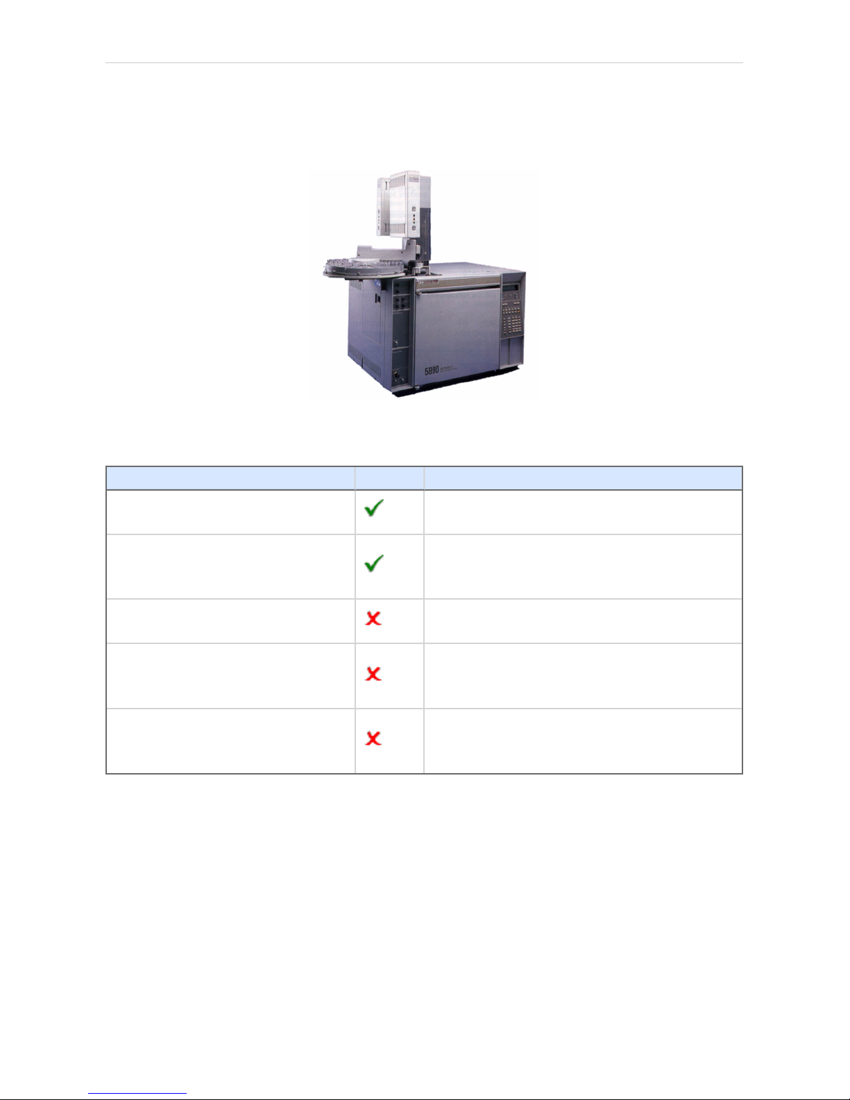
The Agilent 5890 GC driver can control Agilent (formerly HP) 5890A,
5890 Series II and 4890Dchromatographs.
Fig 1: Agilent (HP) 5890 with an autosampler
Tab 1: Control Board compatibility:
Control Board Status Description
19257-60015 HPIB/RS232
Newer type; working; both analog
outputs supported.
19257-60010 HPIB/RS232
Tested in DataApex. Older type;
working; only one analog output is
supported
19242-60010 INET
commonly used with integrators, cannot
be used
19242-60015 INET
commonly used with integrators,
buffered communication, cannot be
used
19242-60030 RS232
RS232 board only, uses different
communication protocol, cannot be
used
- 1 -
Page 6

Agilent 5890 2 Requirements
2 Requirements
Clarity Installation CD ROM with GC Control module (p/n A23).
Caution: The control module does not support EPC, FPD and Analog Input
Board (19261-60010)
Free serial port in the PC (fast - 16550 UART).
Note: Modern computers usually have only 1 (if any) serial (COM) port installed.
To use more devices requiring the port, the MultiCOM adapter (p/n
MC01) is available.
Serial cross DB9F-DB25M cable (p/n SK03).
Note: Cables are not part of Clarity Control Module. It is strongly
recommended to order required cables together with the Control Module.
HPIB/RS232 Interface card set for HP 5890. Can be only obtained from
Agilent or third parties.
Caution: Check the Control Board compatibility table in the chapter "Agilent
5890 GC Control Module" on pg 1.
Note: The Interface card set includes the HP IB/RS232 Ribbon Cable (p/n
KB58-1, Agilent order No. 19257- 60500), Back Panel (p/n KB58 2,
Agilent order No. 19257- 60020) and the Interface card (p/n KB58-3,
Agilent order No. 19257-60015). When using the HPIB card from Agilent,
the Ribbon Cable and Back panel have to be ordered separately.
- 2 -
Page 7

Agilent 5890 3 Installation Procedure
3 Installation Procedure
3.1 GC Chromatograph setup
Installing the interface card in the GC unit
Note: Not necessary if the board is already installed
Unscrew and remove the right-hand panel of the chromatograph
Remove the original INET card
Set up the interface card - all switches on the DIP to the ON position
(closer to the outer edge of the card)
Insert the interface card
Note: On newer interface cards provided by DataApex company is the INET
loop connector disabled and the connection is provided by wires attached
to the back side of the card. If you want to use the loop cable for any
reason, cut off the wires on the back side of the card (Fig 2 on pg 3.).
Install the serial connector at the back of the GC (Models of the first series
5890A do not have a hole for this connector - then it is possible to put the
Cannon 25 connectors on the bottom of the GC)
Fig 2: Installation of the INET card
Switch the GC over to the Global Mode - press successively: . - 3 - ENTER -
ON - CLEAR.
Caution: Digital data acquisition works onlyin GLOBAL mode.
Test the INET loop function . - 7 - ENTER - and after the test - CLEAR.
Note: GC would not send „Ready“signal in local mode.
Analog acquisition alternative
When using A/D converter the GC has to be in Local Mode - press
successively: . - 3 - ENTER - OFF - CLEAR.
- 3 -
Page 8

3 Installation Procedure Clarity Control Module
3.2 Connections
When the HP5890 is controlled by the serial line ( RS232 ), both INET
connectors must be connected, which can be done by wiring on the back
side of the card or INET loop cable.
Communication between AS and PC (COM port) proceeds over standard
serial printer cable - see Fig 6 (modem cable cannot be used).
Note: If serial communication cannot be established and all parameters of
communication are correctly set (speed, parity, etc.), then we
recommend to remeasure the cable according to the following scheme
(especially pin connection 2 and 3).
Fig 3: Serial cross cable DB9F - DB25M
Note: Cables are not part of Clarity Control Module. It is strongly
recommended to order required cables (p/n SK) together with the
Control Module.
- 4 -
Page 9

Agilent 5890 3 Installation Procedure
3.3 Description of connectors:
Signal 1 (2)
12-pin HP connector with output of both analog amplifiers (connected to
detector).
It is possible to plug in both orientations with same function.
Note: Not necessary when using the digitalacquisition.
Remote
12-pin HP connector dedicated to send start signal to Clarity
It is necessary to plug it in proper position according to mark on cable
connector
Not necessary when using digital acquisition
INET
INET loop cable. In case of newer INET cards provided by DataApex
company, no loop cable is needed. The cable connection is replaced by
wiring on the back side of the card.
RS232
25-pin female Cannon connector for direct control and digital acquisition
- 5 -
Page 10

3 Installation Procedure Clarity Control Module
3.4 Installing the GC module in the PC:
Select and if necessary install a fast serial port in the PC.
Caution: In the following procedure the setup of HP 5890 with digital acquisition
(without A/D converters) willbe described.
Install Clarity station; in the HW Setup dialog check the None option
during installation.
Connect the GC to the PC by serial cable; turn the GC power on.
- 6 -
Page 11

Agilent 5890 3 Installation Procedure
3.5 Clarity Configuration
Fig 4: System Configuration
Start the Clarity station by clicking on the icon on the desktop.
Invoke the System Configuration dialog accessible from the Clarity
window using the System - Configuration... command.
Press the Add button ① (see Fig 4 on pg 7 .) to invoke the Available
Control Modules dialog.
You can specify the searching filter ② to simplify the finding of the driver.
Select the 5890 and press the Add ③ button.
- 7 -
Page 12

3 Installation Procedure Clarity Control Module
The Agilent HP5890 Setup dialog will appear.
Fig 5: Agilent HP5890 Setup
In the Agilent HP5890 Setup dialog set COM port, Baud Rate: 19200
Note: Other baud rates can be set according to the DIP switches in the GC unit.
Select the Version.
Check the Digital Acquisition checkbox and fill in the names of your
detectors. Left this checkbox empty only if you intent to collect the detector
signals with another A/D detector.
Check the This Device Starts the Run in Clarity / Clarity Starts This Device
radiobutton. With This Device Starts the Run in Clarity checked, the device
is started prior to Clarity by its front button or autosampler connected to
this device and passes the start to Clarity. When Clarity Starts This Device
is checked, Clarity is started prior to this device by separately wired
autosampler, Start button in Single Run or different device and then starts
this device.
Note: The This Device Starts the Run in Clarity option is checked by
default.
Use the Autodetect button to read in instrument configuration and check
the communication.
Press the OK button.
The Agilent 5890 GC Driver item ④ will appear in the Setup Control
Modules list in the left part of System Configuration dialog.
Switch to the desired Instrument X tab ⑤ in the right part of the System
Configuration dialog.
Note: The Instrument Type must be set to GC.
- 8 -
Page 13

Agilent 5890 3 Installation Procedure
Drag and drop the HP 5890 GC Driver from the Setup Control Modules in
the left to the instrument on the right side⑥ or use the --> button ⑦ . Set
only one detector if you do not wish to acquire both signals
simultaneously.
Press OK button to save the settings and close the configuration window.
- 9 -
Page 14

3 Using the control module Clarity Control Module
3 Using the control module
3.6 Method Setup - GC
Use the From GC button to download current method parameters from
Agilent 5890 (and save it under suitable name). You can use this
procedure to copy the parameters of your methods already stored in the
GC memory to Clarity.
Use the GC Status button to see the current GC configuration (inlets,
detectors etc.)
Note: Note: in DEMO mode it enables selecting them
Use the upper tabs in the Method Setup - GC dialog to set or modify the
GC control parameters.
Fig 6: Method Setup - GC - Oven/Zones
Note: The Time Eventstab is available for Agilent 5890 Series II only.
On the Signals tab, you can assign the Detector (or other signal) to the
output Signals.
- 10 -
Page 15

Agilent 5890 3 Using the control module
In the Method Setup - Acquisition dialog select the voltage range to be
acquired. Signals exceeding this value will be cut.
Note: The acquisition frequency Rate is fixed to 10 Hz for Agilent 5890 with
digitaldata acquisition.
- 11 -
Page 16

Agilent 5890 4 Troubleshooting
4 Troubleshooting
Configuration for two independent detectors
Independent (isothermal) data acquisition on two independent detectors
can be used only with analog data acquisition (using A/D convertor). It
cannot be used with digital data acquisition.
Why there is no data coming from the GC once Start has been pressed?
Most probably you have set the setting to Local Mode instead of Global
Mode. "GC Chromatograph setup" on page3 for more details.
4.1 Commdrv.ini utility
It is possible to record the communication between Clarity and the device.
To activate the recording and specify a file for storing the communication
set the COMx key(s) with following parameters in the COMMDRV.INI file
located in the Clarity installation folder:
[COM1]
echo=On
textmode=on
filename=CommDrv_%D.txt
reset=off
Note: The file can be edited by any text editor (Notepad).
Note: Separate entries can be specified for each Com port.
Note: %D (or %d) in the filename parameter means that the log will be created
separately for each day. The reset=off parameter disables deleting the
content of the log each time the station is started during the same day.
Echo
Off (default) - no communication will be recorded.
Filename
The file where the communication should be stored. If the path is not
specified the file will be stored in the same folder like the COMMDRV.INI
file.
Not received or unrecognized replies will be recorded as “Timeout on
Com line”
The created log file can be viewed in any text editor.
Note: The record is very helpful for troubleshooting the communication between
Clarity and the device.
Reset
On - will erase the log each time the station is restarted (otherwise the log
can increase substantially after some time)
- 12 -
 Loading...