

Page 1

Agilent 490
Micro Gas
Chromatograph
User Manual
Agilent Technologies
Page 2

Notices
CAUTION
WARNING
© Agilent Technologies, Inc. 2017
No part of this manual may be reproduced
in any form or by any means (including
electronic storage and retrieval or translation into a foreign language) without prior
agreement and written consent from
Agilent Technologies, Inc. as governed by
United States and international copyright
laws.
Manual Part Number
G3581-90001
Edition
Sixth edition, November 2017
Printed in China
Agilent Technologies, Inc.
412 Ying Lun Road
Waigoaqiao Freed Trade Zone
Shanghai 200131 P.R.China
Warranty
The material contained in this document is provided “as is,” and is subject to being changed, without notice,
in future editions. Further, to the maximum extent permitted by applicable
law, Agilent disclaims all warranties,
either express or implied, with regard
to this manual and any information
contained herein, including but not
limited to the implied warranties of
merchantability and fitness for a particular purpose. Agilent shall not be
liable for errors or for incidental or
consequential damages in connection
with the furnishing, use, or performance of this document or of any
information contained herein. Should
Agilent and the user have a separate
written agreement with warranty
terms covering the material in this
document that conflict with these
terms, the warranty terms in the separate agreement shall control.
Technology Licenses
The hardware and/or software described in
this document are furnished under a
license and may be used or copied only in
accordance with the terms of such license.
Restricted Rights Legend
(June 1987) or DFAR 252.227-7015 (b)(2)
(November 1995), as applicable in any
technical data.
Safety Notices
A CAUTION notice denotes a
hazard. It calls attention to an operating procedure, practice, or the
like that, if not correctly performed
or adhered to, could result in
damage to the product or loss of
important data. Do not proceed
beyond a CAUTION notice until the
indicated conditions are fully
understood and met.
A WARNING notice denotes a
hazard. It calls attention to an
operating procedure, practice, or
the like that, if not correctly performed or adhered to, could result
in personal injury or death. Do not
proceed beyond a WARNING
notice until the indicated conditions are fully understood and met.
If software is for use in the performance of
a U.S. Government prime contract or subcontract, Software is delivered and
licensed as “Commercial computer software” as defined in DFAR 252.227-7014
(June 1995), or as a “commercial item” as
defined in FAR 2.101(a) or as “Restricted
computer software” as defined in FAR
52.227-19 (June 1987) or any equivalent
agency regulation or contract clause. Use,
duplication or disclosure of Software is
subject to Agilent Technologies’ standard
commercial license terms, and non-DOD
Departments and Agencies of the U.S.
Government will receive no greater than
Restricted Rights as defined in FAR
52.227-19(c)(1-2) (June 1987). U.S. Government users will receive no greater than
Limited Rights as defined in FAR 52.227-14
Page 3

Contents
1 Introduction
Safety Information 8
Important safety warnings 8
Hydrogen safety 8
Safety symbols 9
Safety and regulatory information 10
General safety precautions 10
Shipping Instructions 13
Cleaning 13
Instrument Disposal 13
2 Instrument Overview
Principle of Operation 16
Front View 17
Back View 18
Inside View 19
Carrier Gas Connection 21
Power 23
Power source 23
Power Requirements 23
Disposal 24
Specifications 24
Ambient Pressure 25
Ambient Temperature 25
Maximum Operation Altitude 25
Micro GC Cycle with Constant Pressure 26
Micro GC Cycle with Ramped Pressure 27
3 Installation and Use
Pre-Installation Requirements 30
490 Micro GC User Manual 3
Page 4

Inspect the Shipping Packages 30
Unpack the Micro GC 31
Review the Packing List 32
490 Micro GC Installation 33
Step 1: Connect carrier gas 33
Step 2: Connect to calibration gas or checkout sample 33
Step 3: Install power supply 33
Step 4: Connect to computer or local network 34
Step 5: Install Chromatography Data System 34
Step 6: Assign IP address 34
Restore the Factory Default IP Address 38
Create the Test Method 40
Perform a Series of Runs 41
Shut Down Procedure 42
Long Storage Recovery Procedure 42
4 Sample Gas Handling
5 GC Channels
Using the external filter unit 46
Heated sample lines 47
How to connect your sample to the 490 Micro GC 48
Rear inlet (heated or unheated) 48
Internal inlet 49
Internal bracket for Genie filter 51
490-Micro GC Optional Pressure Regulators 53
G3581-S0003 53
G581-S0004 56
Manual Injection 59
Manual injection guidelines 59
Injection Procedure 60
Field upgrade kits 60
Manual injection flow diagrams 61
Carrier Gas 66
Micro Electronic Gas Control (EGC) 67
Inert Sample Path 67
Injector 67
4 490 Micro GC User Manual
Page 5

Column 68
Molsieve 5Å columns 69
CP-Sil 5 CB columns 70
CP-Sil CB columns 71
PoraPlot 10m column 72
Hayesep A 40 cm heated column 73
COX and AL203/KCI columns 74
MES (NGA) and CP-WAX 52 CB columns 75
Column conditioning 76
Backflush Option 77
Tuning the backflush time (except on a HayeSep A channel) 79
Tuning the backflush time on a HayeSep A channel 80
To disable backflush 81
Backflush to Detector 82
CP-Sil 5 CB Backflush to detector 82
Al2O3 Backflush to detector 82
Tuning the backflush time 83
To disable backflush 85
Set invert signal time 85
Checkout information 86
C6+ Calorific value calculation 88
TCD Detector 88
6 Channel Exchange and Installation
Tools required 90
Replacement procedure for Micro GC channel 91
Replacement procedure for Micro GC channel with RTS option 99
Replacement procedure for Molsieve filters with the RTS option 103
Carrier gas Tube Stop Modification Kit 105
7 Communications
Access the Connection Ports 108
490 Chromatography Data Systems 110
Ethernet Networks 111
IP Addresses 112
Example network configurations 112
USB VICI Valve 116
Configure Multiple VICI Valves with OpenLab EZchrom 116
USB Wi-Fi 118
490 Micro GC User Manual 5
Page 6

8 Errors
Frequently Asked Questions (FAQ) 121
Glossary of network terms 121
External Digital I/O 123
External Analog I/O 124
Error Handling 126
Error List 127
6 490 Micro GC User Manual
Page 7

Agilent 490 Micro Gas Chromatograph
User Manual
1
Introduction
Safety Information 8
Shipping Instructions 13
Cleaning 13
Instrument Disposal 13
This chapter provides important information about using the
Agilent 490 Micro Gas Chromatograph (Micro GC) safely. To
prevent any injury to you or any damage to the instrument it is
essential that you read the information in this chapter.
Agilent Technologies
7
Page 8

1 Introduction
WARNING
WARNING
Safety Information
Important safety warnings
There are several important safety notices that you should always
keep in mind when using the Micro GC.
When handling or using chemicals for preparation or use within
the Micro GC, all applicable local and national laboratory safety
When
practices must be followed. This includes, but is not limited to,
correct use of Personal Protective Equipment, correct use of
storage vials, and correct handling of chemicals, as defined in the
laboratory’s internal safety analysis and standard operating
procedures. Failure to adhere to laboratory safety practices could
lead to injury or death.
Hydrogen safety
Hydrogen is a commonly used GC carrier gas. When mixed with air,
hydrogen can form explosive mixtures and has other dangerous
characteristics.
When using hydrogen (H2) as the carrier gas, be aware that hydrogen gas
can create a fire or explosion hazard. Be sure that the supply is turned off
until all connections are made.
Hydrogen is flammable. Leaks, when confined in an enclosed space, may
create a fire or explosion hazard. In any application using hydrogen, leak
test all connections, lines, and valves before operating the instrument.
Always turn off the hydrogen supply at its source before working on the
instrument.
• Hydrogen is combustible over a wide range of concentrations. At
atmospheric pressure, hydrogen is combustible at concentrations
from 4 % to 74.2 % by volume.
• Hydrogen has the highest burning velocity of any gas.
• Hydrogen has a very low ignition energy.
• Hydrogen that is allowed to expand rapidly from high pressure into
the atmosphere can self-ignite.
• Hydrogen burns with a nonluminous flame which can be invisible
under bright light.
8 490 Micro GC User Manual
Page 9
Safety symbols
Introduction 1
Warnings in the manual or on the instrument must be observed during
all phases of operation, service, and repair of this instrument. Failure
to comply with these precautions violates safety standards of design
and the intended use of the instrument. Agilent Technologies assumes
no liability for the customer’s failure to comply with these
requirements.
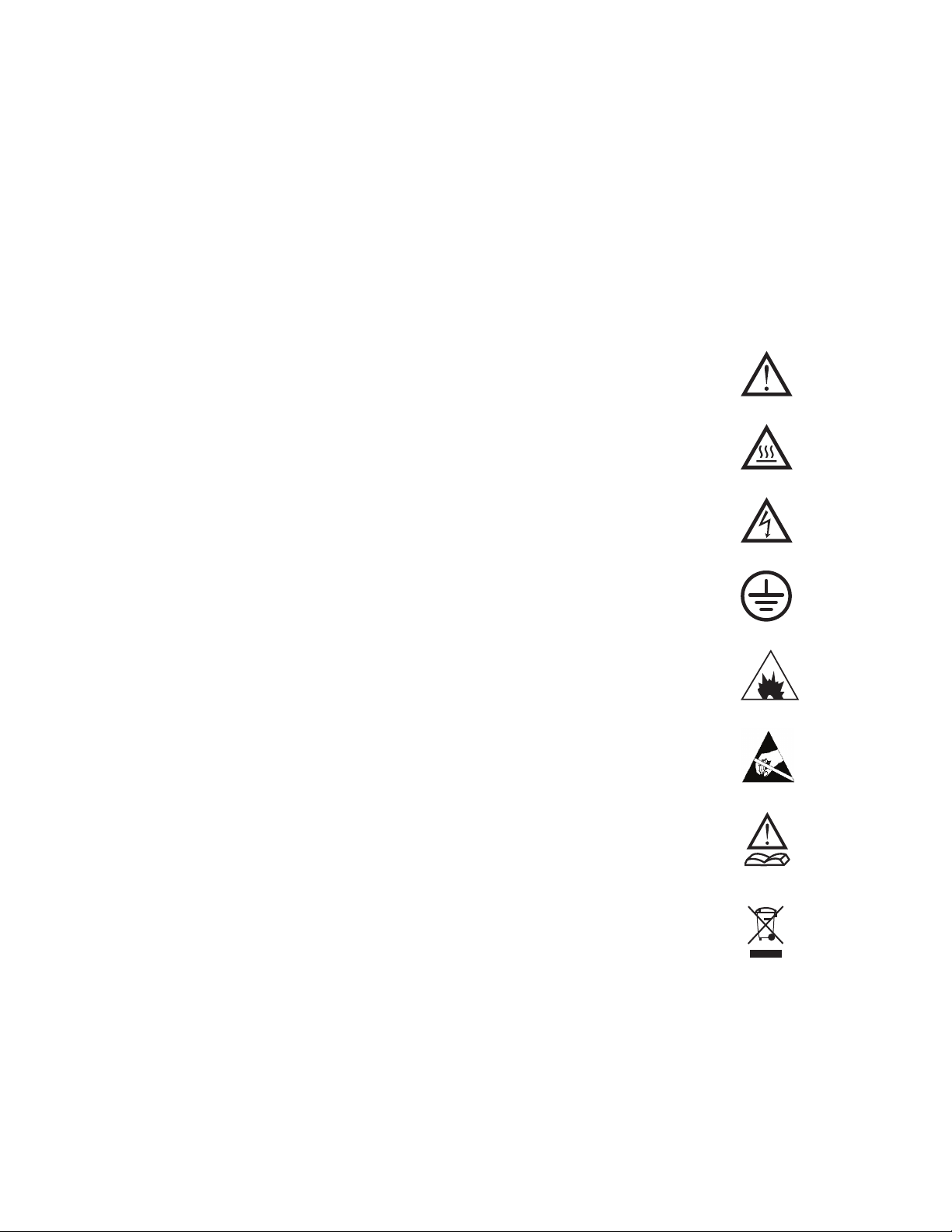
See accompanying instructions for more
information.
Indicates a hot surface.
Indicates hazardous voltages.
Indicates earth (ground) terminal.
Indicates potential explosion hazard.
Indicates electrostatic discharge hazard.
Indicates a hazard. See the Agilent 490 GC user
documentation for the item labeled.
Indicates that you must not discard this
electrical/electronic product in domestic
household waste
490 Micro GC User Manual 9
Page 10

1 Introduction
Safety and regulatory information
This instrument and its accompanying documentation comply
with the CE specifications and the safety requirements for
electrical equipment for measurement, control, and laboratory
use (CEI/IEC 1010-1)
This device has been tested and found to comply with the limits
for a Class A digital device, pursuant to part 15 of the FCC
rules. These limits are designed to provide reasonable
protection against harmful interference when the equipment is
operated in a commercial environment. This equipment
generates, uses, and can radiate radio frequency energy and, if
not installed and used in accordance with the instruction
manual, may cause harmful interference to radio
communications.
Operation of this equipment in a residential area is likely to
cause harmful interference in which case the user will be
required to correct the interference at his own expense.
CSAUS and FCC-b.
C
NOTICE This instrument has been tested per applicable
requirements of EMC Directive as required to carry the
European Union CE Mark. As such, this equipment may be
susceptible to radiation/interference levels or frequencies,
which are not within the tested limits.
General safety precautions
Follow the following safety practices to ensure safe equipment
operation:
• Perform periodic leak checks on all supply lines and
pneumatic plumbing.
• Do not allow gas lines to become kinked or punctured. Place
lines away from foot traffic and extreme heat or cold.
• Store organic solvents in fireproof, vented and clearly
labeled cabinets so they are easily identified as either toxic,
or flammable, or both types of materials.
• Do not accumulate waste solvents. Dispose of such materials
through a regulated disposal program and not through
municipal sewage lines.
10 490 Micro GC User Manual
Page 11

Introduction 1
WARNING
WARNING
This instrument is designed for chromatographic analysis of
appropriately prepared samples. It must be operated using
appropriate gases or solvents and within specified maximum
ranges for pressure, flows, and temperatures as described in this
manual. If the equipment is used in a manner not specified by the
manufacturer, the protection provided by the equipment may be
impaired.
It is the responsibility of the customer to inform Agilent customer
support representatives if the instrument has been used for the
analysis of hazardous samples, prior to any instrument service
being performed or when an instrument is being returned for
repair.
• Avoid exposure to potentially dangerous voltages.
Disconnect the instrument from all power sources before
removing protective panels.
• When it is necessary to use a non-original power cord and
plug, make sure the replacement cord adheres to the color
coding and polarity described in the manual and all local
building safety codes.
• Replace faulty or frayed power cords immediately with the
same type and rating.
• Place this instrument in a location with sufficient ventilation
to remove gases and vapors. Make sure there is enough space
around the instrument for it to cool off sufficiently.
• Before plugging the instrument in or turning the power on,
always make sure that the voltage and fuses are set
appropriately for your local power source.
• Do not turn on the instrument if there is a possibility of any
kind of electrical damage. Instead, disconnect the power cord
and contact your local Agilent sales office.
• The supplied power cord must be inserted into a power
outlet with a protective ground connection. When using an
extension cord, make sure that the cord is also properly
grounded.
• Do not change any external or internal grounding
connections, as this could endanger you or damage the
instrument.
490 Micro GC User Manual 11
Page 12

1 Introduction
• The instrument is properly grounded when shipped. You do
not need to make any changes to the electrical connections or
to the instrument chassis to ensure safe operation.
• When working with this instrument, follow the regulations
for Good Laboratory Practices (GLP). Take care to wear
safety glasses and appropriate clothing.
• Do not place containers with flammable liquids on this
instrument. Spilling liquid over hot parts may cause fire.
• This instrument may use flammable or explosive gases, such
as hydrogen gas under pressure. Before operating the
instrument be sure to be familiar with and to follow
accurately the operation procedures prescribed for those
gases.
• Never try to repair or replace any component that is not
described in this manual without the assistance of an Agilent
service engineer. Unauthorized repairs or modifications will
result in rejection of warranty claims.
• Always disconnect the AC power cord before attempting any
type of maintenance.
• Use proper tools when working on the instrument to prevent
danger to you or damage to the instrument.
• Do not attempt to replace any battery or fuse in this
instrument other than as specified in the manual.
• Damage can result if the instrument is stored under
unfavorable conditions for prolonged periods. (For example,
damage will occur if stored while subject to heat, water, or
other conditions exceeding the allowable operating
conditions).
• Do not shut off column flow when the oven temperature is
high, since this may damage the column.
• This unit has been designed and tested in accordance with
recognized safety standards and designed for use indoors.
• If the instrument is used in a manner not specified by the
manufacturer, the protection provided by the instrument
may be impaired.
• Substituting parts or performing any unauthorized
modification to the instrument may result in a safety hazard.
• Changes or modifications not expressly approved by the
responsible party for compliance could void the user's
authority to operate the equipment.
12 490 Micro GC User Manual
Page 13

Shipping Instructions
Cleaning
Introduction 1
If your Micro GC must be shipped for any reason, it is very
important to follow these additional shipping preparation
instructions:
• Place all the vent caps on the back of the Micro GC (see
Figure 3 on page 18).
• Always include the power supply.
• Include, if used, the inlet filter(s).
To clean the surface of the Micro GC:
1 Switch the Micro GC off.
2 Remove the power cable.
Instrument Disposal
3 Put protection plugs on the sample and carrier gas inlets.
4 Put protection plugs on the column vents.
5 Use a soft brush (not hard or abrasive) to carefully brush
away all dust and dirt.
6 Use a soft, clean cloth dampened with mild detergent to
clean the outside of the instrument.
• Never clean the inside of the instrument.
• Never use alcohol or thinners to clean the instrument;
these chemicals can damage the case.
• Be careful not to get water on the electronic components.
• Do not use compressed air to clean the instrument.
When the Micro GC or its parts have reached the end of their
useful life, dispose of them in accordance with the
environmental regulations that are applicable in your country.
490 Micro GC User Manual 13
Page 14

1 Introduction
14 490 Micro GC User Manual
Page 15

Agilent 490 Micro Gas Chromatograph
User Manual
2
Instrument Overview
Principle of Operation 16
Front View 17
Back View 18
Inside View 19
Carrier Gas Connection 21
Power 23
Ambient Pressure 25
Ambient Temperature 25
Maximum Operation Altitude 25
Micro GC Cycle with Constant Pressure 26
Micro GC Cycle with Ramped Pressure 27
There are several versions of the Agilent 490 Micro GC. All of
them use GC channels, each of which consists of an Electronic
Gas Control (EGC) injector, column, and detector.
The Micro GC is a self-contained package with all of the normal
GC components. It is available as a dual channel cabinet version
(one or two GC channels) or a quad channel cabinet version (up
to four GC channels). A computer with a chromatography data
system (CDS) is needed to complete the system.
This chapter provides a brief overview of the 490 Micro GC.
Agilent Technologies
15
Page 16
2 Instrument Overview
Principle of Operation
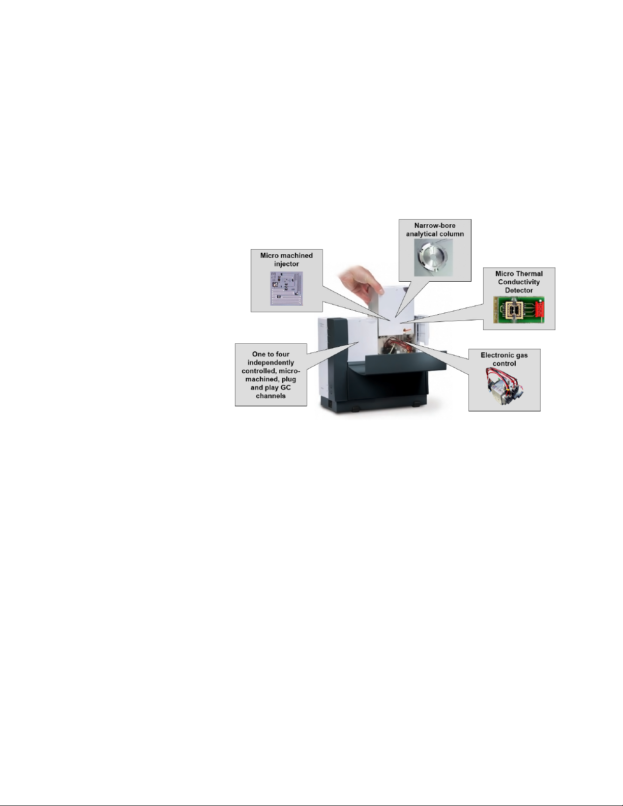
The 490 Micro GC can be equipped with one to four
independent column channels. Each column channel is a
complete, miniaturized GC with electronic carrier gas control,
micro-machined injector, narrow-bore analytical column and
micro thermal conductivity detector (µ TCD), Figure 1.
Figure 1 490 Micro GC setup
The 490 Micro GC analytical channels can optionally be
equipped with a back flush option. The advantages include the
protection of the stationary column phase against moisture and
carbon dioxide. Next to that, it results in shorter analysis times
as late elution compounds, which are not of interest, do not
enter the analytical column.
16 490 Micro GC User Manual
Page 17
Front View
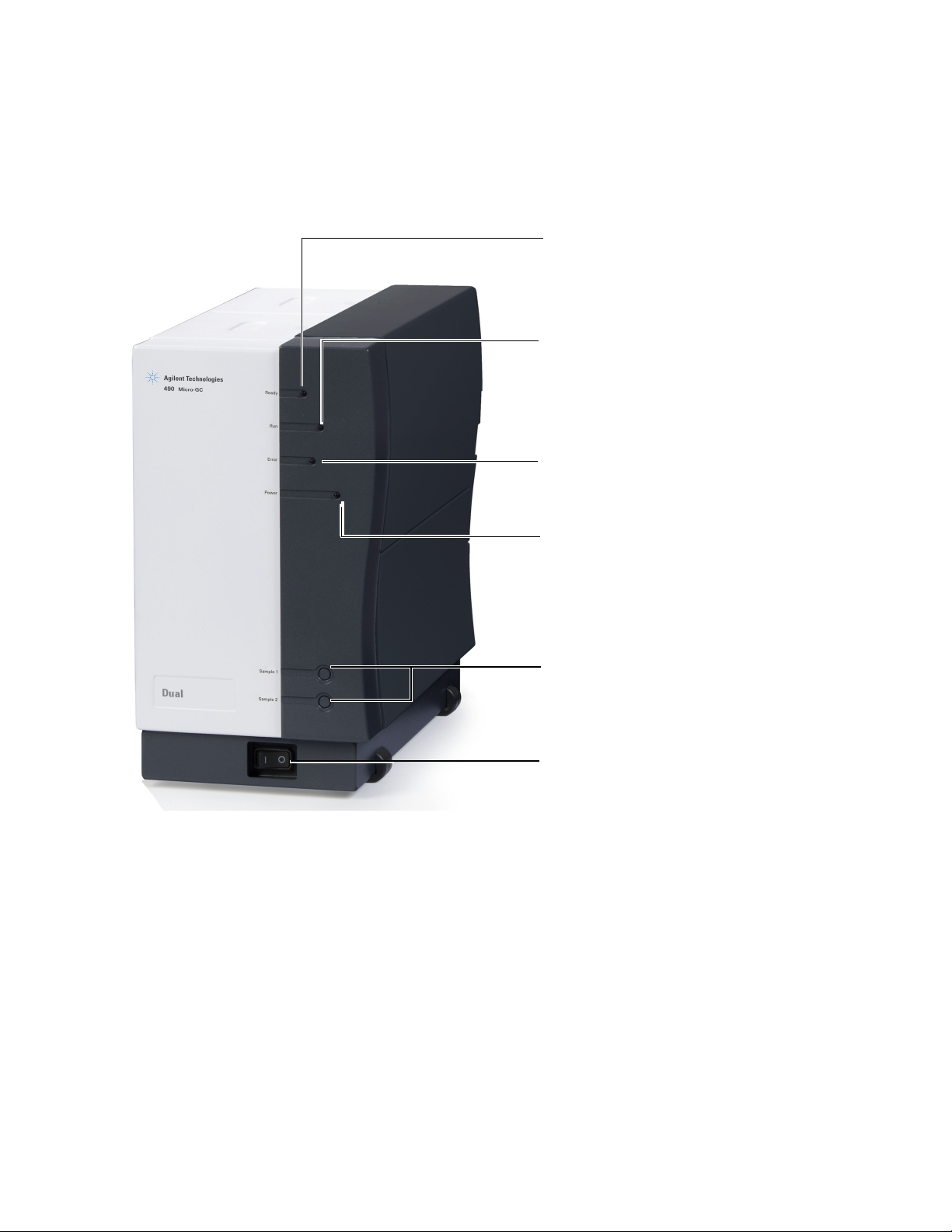
Ready LED
LED OFF: System not ready
LED ON: System is ready
Run LED
LED OFF: No run
LED blinking: Run in progress
Error LED
LED OFF: No error
LED blinking: Error present
See “Error List” on page 127
Power LED
LED OFF: No power
LED ON: Power OK
LED blinking: Voltage < 10 Volt
Sample 1 and Sample 2
Sample gas inlet connector (for unheated front
inlets)
See “Manual Injection” on page 59
Power On/Off Switch
Switch the Micro GC ON or OFF
Instrument Overview 2
Figure 2 Front view of the 490 Micro GC
490 Micro GC User Manual 17
Page 18
2 Instrument Overview
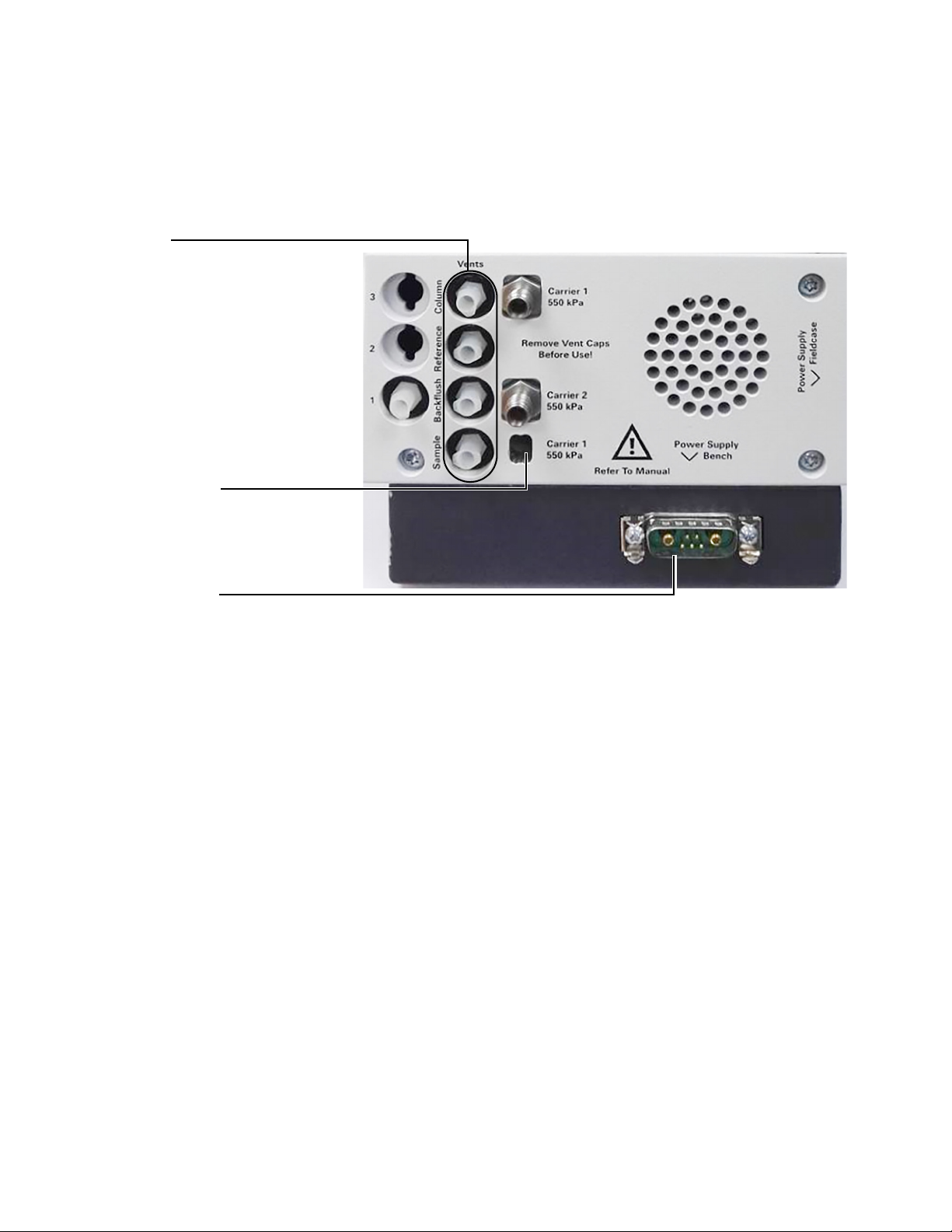
Power connector
Power connector (male)
See “Power” on page 23
Vents
It is possible to connect long vent lines to
these fittings in order to safely guide
hazardous fumes to a fume hood or other
appropriate vent.
Carrier gas input
Carrier gas input connector
See “Carrier Gas Connection” on
page 21
Back View
Figure 3 Back view of the 490 Micro GC
18 490 Micro GC User Manual
Page 19

Inside View
Assign IP address switch
See “Ethernet Networks” on
page 111.
LAN indicators
Red LED: Transmit data
Green LED: Receive data
Ethernet (LAN)
connector
Ethernet RJ45
connector.
See “Ethernet
Networks” on page 111.
COM 1
RS-232 communication
interface
Digital I/O
Digital input and output
signals, such as
start_stop, ready_out,
and start_in.
See “External Digital
I/O” on page 123.
COM 3 and COM 4
RS-485 (4-wire)
communication interface.
See Table 1 on page 20.
Analog I/O
External analog I/O signals.
See “External Analog
I/O” on page 124.
COM 2
RS-232 (2-wire)
communication interface.
See “490 Chromatography
Data Systems” on
page 110.
USB
communication interface.
See “USB VICI Valve” on
page 116 and “USB
Wi-Fi” on page 118
SD Card Slot
No function supported.
Instrument Overview 2
Open the right side cover and the cable connectors will be
visible. See Figure 4.
Figure 4 Cable connectors (main board G3581-65000 shown)
490 Micro GC User Manual 19
Page 20

2 Instrument Overview
The Micro GC provides communications ports as shown in
Table 1, depending on the model.
Table 1 Micro GC communication ports
Port Connection 490 Micro GC 490-Mobile Micro GC 490-PRO Micro GC
LAN Ethernet Interface with PC Interface with PC Interface with PC
COM 1 RS232 Not available Not available Valco stream selector;
Serial MODBUS
COM 2 RS232 Valco stream selector
Field case
†
LCD
COM 3 RS485
RS232
RS422
COM 4 RS485
RS232
RS422
Not available
Not available
Not available
Not available
Not available
Not available
Valco stream selector
Field case
†
LCD
Not available
Not available
Not available
Not available
Not available
Not available
Valco stream selector;
Serial MODBUS
†
LCD
Serial MODBUS
Not available
Not available
Serial MODBUS
Not available
Not available
*
*
;
*
*
Analog I/O Analog I/O Analog I/O Analog I/O
Digital I/O Digital I/O;
ready in - ready out;
start in - start out;
extension boards
‡
USB VICI Valves, WIFI interface VICI Valves, WIFI interface,
Digital I/O;
ready in - ready out;
start in - start out;
extension boards
‡
USB Storage
Digital I/O;
ready in - ready out;
start in - start out;
extension boards
‡
VICI Valves, WIFI interface,
USB Storage
* Optional PRO license required
† Optional accessory
‡ Extension boards not included
20 490 Micro GC User Manual
Page 21

Carrier Gas Connection
CAUTION
Instrument Overview 2
The carrier gas line is connected to the Micro GC at the back
panel Carrier 1 or Carrier 2 port.
Do not use any kind of plastic tubing since air will diffuse through the
tubing, which may cause noisy baselines and decreased sensitivity. The
metal tubing must be clean for GC use. Buy either flamed or chromatographically clean tubing.
Specifications for the carrier gas:
Pressure: 550 kPa ± 10 kPA (80 psi ± 1.5 psi)
Purity: 99.999 % minimum
Dry and free of particles: Gas Clean filters recommended
Gas Clean filters are recommended to remove any traces of
moisture and oxygen. For low-level analysis, consider using a
better grade of carrier gas.
Gas Clean filters are filled with nitrogen. If you are not using
nitrogen as the carrier gas, flush filters and gas lines after
installation of a new filter.
The type of analysis you want to perform dictates the type of
carrier gas to use. The difference between the relative thermal
conductivity of the carrier gas and the sample components
should be as high as possible. See Table 2 for several relative
thermal conductivities.
Table 2 Relative thermal conductivities
Relative thermal
Carrier gas
Hydrogen 47.1 Ethane 5.8
Helium 37.6 Propane 4.8
Methane 8.9 Argon 4.6
Oxygen 6.8 Carbon dioxide 4.4
Nitrogen 6.6 Butane 4.3
Carbon monoxide 6.4
conductivities
Carrier gas
Relative thermal
conductivities
490 Micro GC User Manual 21
Page 22

2 Instrument Overview
WARNING
WARNING
Your Micro GC is configured for a specific carrier gas, either
He and H2 or N2 and Ar. Make certain that any carrier gas
selection in your Agilent data system corresponds to the carrier
gas physically connected to your Micro GC. Use only the carrier
gas corresponding to this configuration. If you change the carrier
gas type plumbed to the Micro GC, you must change the
corresponding carrier gas type in the data system.
Hydrogen is flammable. If you are using hydrogen as a carrier gas,
pay particular attention to possible leaks at connections inside
and outside of the Micro GC (use an electronic leak tester).
22 490 Micro GC User Manual
Page 23

Power
CAUTION
Instrument Overview 2
Power source
• 90 to 264 Vac, frequency between 47 to 63 Hz.
• The room power outlet circuit must be exclusively reserved
for the instrument(s).
• The network should be properly grounded.
• Installation Category (overvoltage category): II
Power Requirements
The Micro GC requires 12 V Vdc, 150 W.
The Gasifier requires 12 V Vdc, 150 W.
Only use the power supply provided with your Micro GC.
This Power Supply, see Figure 5, is tailored to meet the power
needs of your Micro GC. See Table 3 on page 24 for
specifications.
Figure 5 Model GST220A12-AG1 (P/N G3581-60080)
490 Micro GC User Manual 23
Page 24

2 Instrument Overview
Disposal
Specifications
Disposal of the Power Supply must be carried out in accordance
with all environmental regulations applicable in your country.
Table 3 Power supply specifications
Feature Model: GST220A12-AG1
Input voltage 85 Vac to 264 Vac
Input frequency 47-63 Hz
Inrush current 120A/230VAC
Output voltage 12.0 Vdc
Voltage adjust ± 5 %
Output power 180 W
Over voltage protection 105 %-135 % rated output voltage
Ripple and noise 80mV Vp-p
Operating temperature -30 °C to +70 °C
Storage temperature -40 °C to +85 °C
Humidity 20 % to 90 % non condensing
Safety standard UL60950-1, TUV EN60950-1, BSMI CNS14336, CSA
C22.2, CCCGB4943, PSE J60950-1 Approved
RFI/EMC standard In compliance with CISPR22 (EN55022) Class B and
FCC Part 15/CISPR 22 class B, CNS13438 class B,
GB9254, EN61000-3-2, EN61000-3-3, EN61000-4-2,
EN61000-4-3, EN61000-4-4, EN61000-4-5,
EN61000-4-6, EN61000-4-8, EN61000-4-11 (light
industry level, criteria A)
Dimensions 210 × 85 × 46 mm (L×W×H)
Weight 1.1 kg approximately
24 490 Micro GC User Manual
Page 25

Ambient Pressure
The Micro GC automatically shuts down if the ambient pressure
is greater than 120 kPa.
Ambient Temperature
The Micro GC automatically shuts down if the ambient
temperature exceeds 65 °C.
Maximum Operation Altitude
Certified up to 2000 meters above sea level.
Instrument Overview 2
490 Micro GC User Manual 25
Page 26
2 Instrument Overview
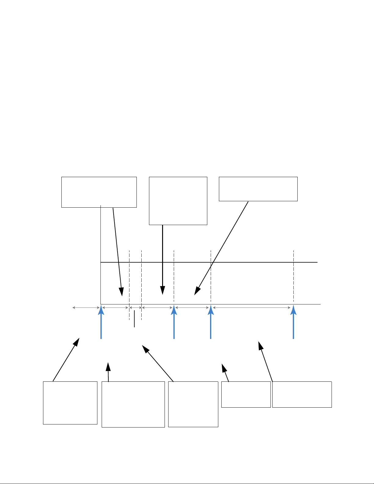
Pressure
Time
Initial
pressure
Run started
Equilibration
time
Sample
time
Pressurization
time
Download
method
Inject time Run time
Inject Start data
acquuisition
Run finished
After the run sampling is
begun. This means that the
sample is (mostly) sucked
into the sample loop.
Pressurization delay
(120 mS), used to
pressurize the sample
to the same pressure
as the column head
pressure.
During injection time the
sample is transported to the
column by the carrier gas.
Before a run is
started all used
method parameters
must be downloaded
via the data system.
Fixed equilibration
delay of 40 ms.
This time allows
the sample to
settle in the
sample loop.
The run can be started
when the Micro GC is
ready (Ready LED is lit).
The data system will wait
until data is received
from the Micro GC.
The real analysis
(run) and data
acquisition starts.
After the specified run
time has elapsed, the
run is finished.
Micro GC Cycle with Constant Pressure
The timing diagram below provides an overview of the constant
pressure cycle of the Micro GC.
This description is only for one channel. In most cases a
dual-channel system is used. When a dual-channel system is
used, the sequence is the same, but the timing settings can
differ. If the sample time on channel A and channel B are
different, the longest time is used for both channels. Also the
run time can be specified per channel; the data acquisition
stops per channel as soon as the run time has elapsed. The total
analysis time depends on the longest run time.
26 490 Micro GC User Manual
Page 27
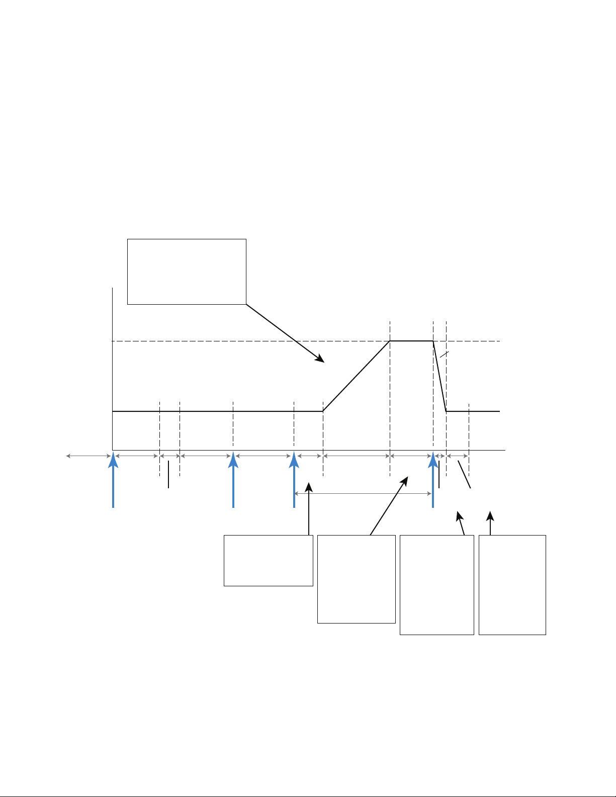
Micro GC Cycle with Ramped Pressure
Pressure
Time
Initial
pressure
Run started
Equilibration
time
Sample
time
Pressurization
time
Download
method
Inject time
Run time
Inject Start data
acquuisition
Run
finished
Final
pressure
Not ready
Pressure
release
Pressure
rise
Ready
Ready
Initial
time
Rise time Final time
Relieve
time
Stabilization
time
The remaining final time depends on the total run time, the duration of
the initial time and the pressure rise. This means that it is possible that
the final time is zero. Another situation is that the final pressure is
limited because of these settings. The software will check all parameter
values and change them into realistic values.
Note: During the run time, there can be only one pressure ramp to a
higher pressure.
The pressure rise is started,
the duration is depending on
two (2) parameters:
• Pressure rise
• Final pressure
Stabilization
time for the
pressure after it
has been
returned to the
initial pressure.
Fixed at 500 mS.
Relieve time, the
time needed to
decrease the
column head
pressure from the
final pressure to
the initial
pressure.
As soon as the
final pressure is
reached, the rise
stops and the final
time begins. The
pressure remains
the same.
During initial time
the column head
pressure remains
the same.
The timing diagram below provides an overview of the ramped
(programmed) pressure cycle of the Micro GC. The timing before
the injection is identical to the constant pressure cycle.
Instrument Overview 2
490 Micro GC User Manual 27
Page 28

2 Instrument Overview
28 490 Micro GC User Manual
Page 29

Agilent 490 Micro Gas Chromatograph
User Manual
3
Installation and Use
Pre-Installation Requirements 30
Inspect the Shipping Packages 30
Unpack the Micro GC 31
Review the Packing List 32
490 Micro GC Installation 33
Restore the Factory Default IP Address 38
Create the Test Method 40
Perform a Series of Runs 41
Shut Down Procedure 42
Long Storage Recovery Procedure 42
This chapter describes how to install and use the instrument.
For an initial installation, an example of a typical packing list is
also included. The actual packing list and included parts
depend on the options ordered.
Agilent Technologies
29
Page 30

3 Installation and Use
Pre-Installation Requirements
Prepare the installation site as described in the Site Preparation
Guide (G3581-90002), including the recommended Gas Clean
filters.
Inspect the Shipping Packages
The Micro GC will arrive in one large box and one or more
smaller cartons. Inspect the cartons carefully for damage or
signs of rough handling. Report damage to the carrier and to
your local Agilent office.
30 490 Micro GC User Manual
Page 31

Unpack the Micro GC
WARNING
CAUTION
Protective shipping
caps
Installation and Use 3
Unpack the Micro GC and accessories carefully and transfer
them to the work area using proper handling techniques.
Inspect the instrument and accessories carefully for damage or
signs of rough handling. Report damage to the carrier and to
your local Agilent office.
Avoid back strain or injury by following all safety precautions
when lifting heavy objects.
The instrument has been protected during shipment by protective caps.
See Figure 6. Before use, remove these caps, including those on the back
panel.
Figure 6 Protective shipping caps
490 Micro GC User Manual 31
Page 32

3 Installation and Use
Review the Packing List
Table 4 shows a typical packing list. The actual packing list and
included parts depend on the options ordered.
Table 4 Typical Micro GC packing list
Item Part number Quantity Units of
measure
Installation Kit Micro GC CP740388 1 EA
CD-ROM - Micro GC - User Information G3581-90010 1 EA
Ethernet crossover cable 2.8m CP740292 1 EA
Locking nut CP420200 4 EA
Male luer CP420100 4 EA
Fittings 1/8 inch Brass 20/pk 5080-8750 1 EA
Tee, 1/8 inch Brass Union 2/PK 5180-4160 1 PK
1/8 in x 0.065in Copper tubing G3581-20061 5 M
External Sample Filter kit CP736729 1 EA
Front and Back ferrule 1/16 CP471201 3 EA
1/16inch Ferrule set SST 0100-1490 3 EA
Stainless Nut 1/16 in 0100-0053 3 EA
Manual User Ext. Sample Filter CP505260 1 EA
Capil. Ext. Filter CP736879 1 EA
Tubing,SS,pre-tsd,1/16in. OD×1.0mm ID,
1/p
Tubing, SS,1/16in. OD×1.0mm ID, 1 mL,
1/p
Fingertight Fitting PEEK CP23050 1 EA
5 FILTERS for EXT. FILTER Assembly CP736467 1 EA
External Filter Male CP736737 1 EA
External Filter FeMale CP736736 1 EA
CP4008 80 MM
CP4009 0.080 M
Micro GC power supply, 12V, 150W G3581-60080 1 EA
32 490 Micro GC User Manual
Page 33

490 Micro GC Installation
Step 1: Connect carrier gas
Installation and Use 3
If you are installing the 490 Micro GC for the first time, follow
the steps as described below.
If you are performing a re-installation, see “Long Storage
Recovery Procedure” on page 42.
Install gas regulators and set pressures
Carrier gas cylinders should have a two-stage pressure regulator to
adjust the carrier gas pressure to 550 kPa ± 10 kPA (80 psi ± 1.5 psi).
Set cylinder regulator pressure to match the gas inlet pressure.
Connect carrier gas to the Micro GC
The Micro GC supports the use of helium, nitrogen, argon and
hydrogen. The recommended purity for carrier gas is 99.999 %
minimum. Connect the carrier gas to the Micro GC Carrier 1
fitting (and Carrier 2 fitting, if available) and turn on the gas
flow. See “Carrier Gas Connection” on page 21.
Step 2: Connect to calibration gas or checkout sample
Install the external filter unit as described in “Using the external
filter unit” on page 46.
For an unheated GC channel: Connect the sample to the Micro
GC using the sample-in connector situated at the front of the
instrument (see “Front View” on page 17).
For a heated GC channel: Connect the sample to the heated
sample as described in “How to connect your sample to the 490
Micro GC” on page 48.
Step 3: Install power supply
Connect the power connector to the Micro GC, and then plug the
power cord into an appropriate power source. See “Power” on
page 23. Ensure the power supply is placed in such a way that the
mains appliance inlet or adapter is easy to reach for the operator, as
it functions as a power disconnect switch.
The Power LED will light. The Ready LED lights when all parameter set
points in the system are reached. (See “Front View” on page 17.)
490 Micro GC User Manual 33
Page 34

3 Installation and Use
Step 4: Connect to computer or local network
Your Micro GC is shipped from the factory with default settings.
The following is relevant information on the factory default
states and settings:
• When the Micro GC is turned on, the power LED lights up
and the system begins the flush cycle procedure. The flush
cycle is a 2-minute cycle in which the various valves are
activated and deactivated to flush entrapped air from the
manifold, valves, and tubing.
• After the flush cycle is finished, the method (the default
method in this case), which was last active before the
instrument was shutdown, is activated.
• All heated zones are set at 30 °C.
• The detector filaments are set to OFF.
The 490 Micro GC requires a connection with a computer, that
has Chromatography Data System installed, for initial method
development. This connection uses TCP/IP over Ethernet or
Wi-Fi via USB. For more details and setup procedures see
“Ethernet Networks” on page 111 or “USB Wi-Fi” on page 118
Step 5: Install Chromatography Data System
For further instructions about installation of the
chromatography data system, see the corresponding
installation manual and help file.
Step 6: Assign IP address
Upon arrival from the factory, the Micro GC has a default static
IP address configured. The active IP address is specified on the
sticker together with the MAC address and the mainboard serial
number (see Table 5 on page 35).
34 490 Micro GC User Manual
Page 35

Installation and Use 3
DHCP Switch
Table 5 Factory default IP address settings
Default IP address 192.168.100.100
Subnet mask 255.255.255.0
Host name microgc
Default Gateway N/A (not used)
To complete this procedure, the Micro GC must be in static
1
IP address Mode. To verify this, be sure the DHCP switch
(indicated as 1 on the mainboard), is in the left position. The
DHCP switch is located on the back of the mainboard. (See
Figure 7).
490 Micro GC User Manual 35
Figure 7 DHCP Switch
2 Change the IP address of your laptop or PC to an address in
the same range as the current IP address as the Micro GC.
3 Start up your web browser.
4 Connect to the Micro GC’s website. Type the IP address of
the Micro GC in the address field of the web browser.
5 On the web page, click Network.
6 Log in as administrator. Use the factory default login and
password:
• Login name: admin
• Password: agilent
Page 36

3 Installation and Use
Figure 8 Web server authentication
7
In the network webpage, the upper section shows the
current IP configuration. Type the IP Address, Subnet mask,
and Gateway you want to assign to the Micro GC in the
corresponding fields.
Figure 9 Micro GC website
8 Click Save to save the IP configuration.
36 490 Micro GC User Manual
Page 37

Installation and Use 3
This IP address is now the active IP address.
9
Communication with the Micro GC will be lost, since the
active IP address has changed.
10 Change the IP address of your laptop or PC to an address in
the same range as the new IP address of the Micro GC.
11 To reestablish communication, type the new IP address in
the web browser address bar.
Step 7: Complete Micro GC configuration in Chromatography Data System
1 If not already configured, complete any additional
configuration for the Micro GC in the Chromatography Data
System. Ensure the carrier gas types match the gas actually
supplied to the Micro GC.
2 Start the Micro GC’s online instrument session.
490 Micro GC User Manual 37
Page 38

3 Installation and Use
Restore the Factory Default IP Address
Shipped from the factory, the 490 Micro GC (with mainboard
G3581-65000) is configured with a default static IP address, see
Table 6 on page 39 for the settings. A reset button on the
mainboard enables the possibility to restore these default IP
settings when required. When IP address setting are not known,
this functionality can be used to be able to reconnect to the
instrument and change to custom IP settings.
Figure 10 Reset button on mainboard
The reset button can be accessed behind the right panel on the
mainboard, see Figure 10. To restore the factory default IP
address, follow this procedure:
1 Power off the Micro GC.
2 Press and hold the reset button and power on the Micro GC.
3 Release the reset button shortly after powering on the GC
(approximately 3 seconds).
Note 1: When the reset button is released too quickly (less
than 1 second), it may result in the IP setting not reverting
to its factory defaults.
38 490 Micro GC User Manual
Page 39

Installation and Use 3
Note 2: Holding the reset button too long (more than
10 seconds), will result in an instrument reboot, without
restoring the default IP settings.
4 The default IP address is now restored. See Table 6 for
details.
Table 6 Factory default IP address settings
Default IP address 192.168.100.100
Subnet mask 255.255.255.0
Host name microgc
Default Gateway N/A (not used)
490 Micro GC User Manual 39
Page 40

3 Installation and Use
CAUTION
Create the Test Method
At first startup, perform a checkout to make sure the Micro GC
is functioning properly.
A test method for each standard column type has been provided
in the sections listed in Table 7.
If you ordered a Molsieve column, make sure it is conditioned before use.
See Tab le 10 on page 69 for parameters.
Table 7 Test method listings
Column type Table
Molsieve 5Å Table 10 on page 69
CP Sil 5 CB Table 11 on page 70
CP Sil CB Table 12 on page 71
PoraPlot 10 m Table 13 on page 72
Hayesep A 40 cm Table 14 on page 73
CO
1 m and AL2O3/KCI Table 15 on page 74
x
MES(NGA) and CP-WAX 52 CB Table 16 on page 75
Use the data system to set up the checkout parameters for each
GC channel. Apply the checkout method settings to the Micro
GC and allow the instrument to stabilize at the initial operating
conditions. Monitor the instrument status using the data
system’s status display (refer to the data system help for
details).
Each test method has been designed to determine if the
instrument channel is functioning properly and includes an
example test chromatogram.
40 490 Micro GC User Manual
Page 41

Perform a Series of Runs
Installation and Use 3
1 Create a short sequence of at least three runs using the test
sample and method.
2 Run the sequence.
3 After the first run, the results for each channel should
become similar to the example chromatograms.
490 Micro GC User Manual 41
Page 42

3 Installation and Use
CAUTION
Shut Down Procedure
The detector can be damaged by improper shut down. If shutting
down the instrument for more than a few days, carry out the procedure below.
1 Create a method for all channels with these settings:
• Filaments switched OFF.
• Column temperature set at 30 °C.
• Injector temperature set at 30 °C.
• Pressure set at 50 kPa.
2 Apply the method to the Micro GC.
3 Wait until the temperature of the columns and injectors are
< 40 °C (to protect the column), then switch off the Micro
GC.
4 Remove the carrier gas tubing and plug all the vents and
carrier gas connections with 1/8-inch brass nuts or plastic
caps.
Before using the instrument again, perform the “Long Storage
Recovery Procedure” described below.
Long Storage Recovery Procedure
Follow this recovery procedure if your Micro GC has been
stored for a long period of time.
1 Remove the 1/8-inch brass nuts and plastic caps from all of
the vents and carrier gas connections.
2 Connect the carrier gas tubing and apply pressure to the
Micro GC. Refer to the Site Preparation Guide for supply
pressures and other gas requirements.
3 Wait at least 10 minutes before switching ON the Micro GC.
4 Immediately check if the detector filaments are switched
OFF. Switch OFF if necessary.
42 490 Micro GC User Manual
Page 43

Installation and Use 3
Set the column(s) temperature(s) to the maximum allowed
5
temperature (160 °C or 180 °C depending on the column
limit).
6 Condition the GC column, preferably overnight. This will
ensure that all the water has been removed from the column
module and no damage will occur to the TCD filaments.
490 Micro GC User Manual 43
Page 44

3 Installation and Use
44 490 Micro GC User Manual
Page 45

Agilent 490 Micro Gas Chromatograph
CAUTION
User Manual
4
Sample Gas Handling
Using the external filter unit 46
Heated sample lines 47
How to connect your sample to the 490 Micro GC 48
490-Micro GC Optional Pressure Regulators 53
Manual Injection 59
The Micro GC is built for the analysis of gases and vapors only.
You are advised to prepare a noncondensing gaseous standard
sample for routine checkup of the instrument. Sample pressure
should be between 0 and 100 kPa (0 to 15 psi), the temperature
between 0 and 110 °C ± 5 °C of the analyzer ambient
temperature, and it must be filtered, preferably through a 5-mm
filter. Agilent always recommends the use of the external filter
kit (CP736729) between the injector and the sampling device.
For more details, see “Using the external filter unit” on page 46.
Liquids will seriously damage the instrument and should be avoided!
Agilent Technologies
45
Page 46

4 Sample Gas Handling
Filter female
(CP736736)
Filter male
(CP736737)
From
sample line
Filter element 5 microns
(CP736467, 5 pieces)
To “Sample In”
Micro GC
1/16-inch nut
Finger tight fitting
(CP23050)
1/16-inch nut
From
sample line
Filter element 5 microns
(CP736467, 5 pieces)
1/16-inch nut
1/16 inch nut and
front and back ferrule
Filter female
(CP736736)
Filter male
(CP736737)
To ”Sa mpl e In”
Micro GC
1/16-inch nut
Using the external filter unit
The male part of the filter must be hand-tightened into the
female part, followed by a 1/8 turn with a 7/16-inch wrench. See
Figure 11 as shown below and Figure 12 on page 46. Orient the
arrow on the female half of the filter towards the fingertight
fitting.
Replace the external filter unit at regular intervals. See “Review
the Packing List” on page 32 for part numbers.
Figure 11 Unheated injector connection
Figure 12 Heated injector connection
Whenever possible, remove moisture from samples introduced
to the Micro GC.
46 490 Micro GC User Manual
Page 47

Heated sample lines
Sample Gas Handling 4
A heated sample line is always combined with a heated injector.
A heated injector and sample line is an option for a channel
unit, and is used to prevent sample from condensing in the
sample lines when analyzing condensable samples.
The heated sample and injector can be controlled between 30 °C
and 110 °C.
490 Micro GC User Manual 47
Page 48

4 Sample Gas Handling
WARNING
Male 1/16-inch
Swagelok fitting
CAUTION
How to connect your sample to the 490 Micro GC
The following sections describe how to connect your sample to
the 490 Micro GC depending on the sample inlet configuration.
The metal surfaces of the sample line heater can be very hot.
Before connecting a sample line, allow the sample line heater to
cool down to ambient temperature.
Rear inlet (heated or unheated)
Connect the sample line to the heated or unheated sample inlet
at the rear of the Micro GC using 1/16-inch male Swagelok
fittings.
Figure 13 Rear sample inlet
Insulate the sample line connected to the Micro GC to prevent damage to
communications cables.
48 490 Micro GC User Manual
Page 49

Internal inlet
Internal sample inlet –
1/16-inch Swagelok fitting
Sample Gas Handling 4
For connecting the micro-gasifier, Enrichment and Desorption
Unit (EDU) and a heat-traced sample line, the system's internal
sample inlet should be used.
Figure 14 Open the side panel, remove the top insulation and loosen the internal sample inlet.
490 Micro GC User Manual 49
Figure 15 Remove the rear panel by unscrewing the three bolts.
Page 50

4 Sample Gas Handling
Internal sample inlet –
1/16-inch Swagelok fitting
Figure 16 Remove the PEEK block by unscrewing two bolts.
Figure 17 Install the back panel and micro-gasifier, and connect the
micro-gasifier sample line to the internal sample inlet using a
1/16-inch Swagelok fitting.
50 490 Micro GC User Manual
Page 51

Sample Gas Handling 4
Micro-gasifier vent – 1/16-inch Swagelok fitting
Micro-gasifier sample inlet – 1/16-inch Swagelok fitting
Figure 18 Sample line and vent line connection of the micro-gasifier.
Internal bracket for Genie filter
This section explains how to connect your sample if an optional
internal bracket with Genie filter(s) is installed on your 490
Micro GC.
Connect the sample line to the rear inlet of the 490 Micro GC
using 1/16-inch Swagelok fittings. The Genie filter outlet is
pre-plumbed and connected to the Micro GC column channels.
490 Micro GC User Manual 51
Page 52

4 Sample Gas Handling
Bolts for membrane
Genie filter
Bypass
Rear sample inlet -
Inspection and exchange
1/16-inch Swagelok fitting
CAUTION
Figure 19 Internal bracket with Genie filters.
Ensure separated liquids are properly drained via the bypass tubing outside of the Micro GC. To operate properly, the bypass must remain free of
blockage.
To access the Genie filter membrane for inspection or exchange,
unscrew the two bolts, identified in Figure 19, and lift the upper
part of the filter.
52 490 Micro GC User Manual
Page 53

490-Micro GC Optional Pressure Regulators
Agilent offers two optional sample inlet pressure regulator
assemblies for the 490-PRO Micro GC. These assemblies are
provided fully assembled and require field installation on the
rear of the GC.
G3581-S0003 provides a pressure regulator, Genie filter (for
sample drying) and needle valve, along with the required
mounting bracket and hardware required for installation.
G3581-S0004 provides a pressure regulator and needle valve,
along with the required mounting bracket and hardware
required for installation.
Installation instructions for both assemblies are provided
below.
G3581-S0003
Sample Gas Handling 4
The Agilent pressure regulator assembly (G3581-S0003)
provides a pressure regulator, Genie filter (for sample drying)
and needle valve, along with the required mounting bracket and
hardware required for installation.
Figure 20 shows the components and connection points for the
Agilent pressure regulator assembly (G3581-S0003).
Dried sample to
analytical channels -
rear sample inlet of GC
Out
Genie 170
In Vent
Pressure
regulator
Sample
IN
Needle
valve
Sample
OUT
(Drain)
Figure 20 Agilent pressure regulator assembly (G3581-S0003) functional
block diagram
490 Micro GC User Manual 53
Page 54

4 Sample Gas Handling
NOTE
WARNING
The pressure regulator is factory set, and has been tested to the
following, fixed specifications:
Attribute Specification
Input 25 bar (2.5 Mpa)
Output 0.7 bar (10.1 psi or 70 Kpa)
Flow 20 mL/min
The sample flows through the pressure regulator and into the
Genie filter. Dried sample is then applied to the rear sample
inlet of the GC.
The minimum working pressure of the Genie filter is 0.5 bar. Sample will
not flow through the filter if this working pressure is not maintained.
Vented sample flows through a needle valve for draining.
G3581-S0003 Installation
The G3581-S0003 pressure regulator assembly is supplied fully
assembled, and ready to install at the rear of the GC. To install
the assembly, do the following:
1 Shut down the GC, and allow the column and injector to
cool. See “Shut Down Procedure” on page 42.
The metal surfaces of the column, injector and sample inlet can be
very hot. Before connecting a sample line, allow the GC
components to cool to ambient temperature.
2 At the rear of the GC, disconnect any existing sample line
from the rear sample inlet.
54 490 Micro GC User Manual
Page 55

Sample Gas Handling 4
Rear sample inlet
Lower mounting
bolt
Sample IN
Needle valve
Sample OUT
(drain)
Sample to rear
sample inlet
Figure 21 Rear sample inlet and lower mounting bolt
Remove the lower mounting bolt from the rear panel of the
3
GC.
4 Position the G3581-S0003 pressure regulator assembly at
the rear of the GC, and secure using the lower mounting
bolt.
Figure 22 G3581-S0003 pressure regulator assembly installed
490 Micro GC User Manual 55
5 Connect the filter outlet to the sample inlet on the rear of
the GC using a 1/16 inch Swagelok fitting.
Page 56

4 Sample Gas Handling
WARNING
G581-S0004
The pressure regulator has a maximum inlet pressure of 3,000 psi.
Applying higher pressures may result in serious personal injury
and equipment damage.
6
Connect the Sample IN port on the pressure regulator to the
sample input line.
7 Start the GC (see “Long Storage Recovery Procedure” on
page 42).
8 Leak test the system to ensure that all connections are leak
free.
G3581-S0004 provides a pressure regulator and needle valve,
along with the required mounting bracket and hardware
required for installation.
The block diagram below shows the components and connection
points for the G3581-S0004 pressure regulator assembly.
Sample to rear sample
inlet of GC
Pressure
regulator
Sample
IN
Needle
valve
Sample
OUT
(Drain)
Figure 23 G3581-S0004 pressure regulator assembly functional block
diagram
The pressure regulator is factory set and has been tested to the
following, fixed specifications:
Attribute Specification
Input 25 bar (2.5 Mpa)
Output 0.7 bar (10.1 psi or 70 Kpa)
Flow 20 mL/min
The sample flows through the pressure regulator and into the
rear sample inlet of the GC.
A needle valve provides for venting the sample for draining.
56 490 Micro GC User Manual
Page 57

Sample Gas Handling 4
WARNING
Rear sample inlet
Lower mounting
bolt
G3581-S0004 Installation
The G3581-S0004 sample inlet pressure regulator assembly is
supplied fully assembled and ready to install at the rear of the
GC. The install the assembly, do the following:
1 Shut down the GC and allow the column and injector to cool.
See “Shut Down Procedure” on page 42.
The metal surfaces of the column, injector and sample inlet can be
very hot. Before connecting a sample line, allow the GC
components to cool to ambient temperature.
2 At the rear of the GC, disconnect any existing sample line
from the rear sample inlet.
Figure 24 Rear sample inlet and lower mounting bolt
3 Remove the lower mounting bolt from the rear panel of the
GC.
490 Micro GC User Manual 57
Page 58

4 Sample Gas Handling
Sample IN
Needle valve
Sample OUT
(drain)
Sample to rear
sample inlet
WARNING
4
Position the G3581-S0004 assembly at the rear of the GC and
the secure using the lower mounting bolt.
Figure 25 G3581-S0004 installed
5 Connect the regulator outlet to the sample inlet on the rear
of the GC using a 1/16 inch Swagelok fitting.
The pressure regulator has a maximum inlet pressure of 3,000 psi.
Applying higher pressures may result in serious personal injury
and equipment damage.
6 Connect the Sample IN port on the pressure regulator to the
sample input line.
7 Start the GC (see “Long Storage Recovery Procedure” on
page 42).
8 Leak test the system to ensure that all connections are leak
free.
58 490 Micro GC User Manual
Page 59

Manual Injection
Front sample inlet –
1/16-inch fitting (internal)
Sample Gas Handling 4
Manual injection is possible with the optional front inlet
installed that can accommodate a 1/16-inch sample line. Refer
to the Agilent 490 Micro GC Manual Injection Port Field Kit
documentation (G3581-90000) for detailed information.
Figure 26 Front inlet (unheated)
Manual injection guidelines
• Use sample pump mode and set sampling time 10-20 seconds
in the method. This clearly marks when injector loop is
flushed (sound of the pump). Then gently push the syringe
during that period.
• Flush the sample path 6-10 times. Bulkhead union,
additional tubing, pressure relieve valve, and ball valve adds
dead volume to the system, estimated at 500 to 1000 µl.
• Total sample volume is dependent on the internal volume of
the Micro GC (option# 060-063 have different internal
volumes) and the number of times flushed and the sampling
time in the method.
490 Micro GC User Manual 59
Page 60

4 Sample Gas Handling
NOTE
Injection Procedure
1 Use pump mode (configuration)
2 Measure total pump flow (rear of the instrument)
3 Calculate required pump time that sample path is flushed
sufficiently (6 to 10 times)
4 Initiate sequence in software, use manual trigger type in
method (OLCDS)
5 Insert or connect syringe and start the run
6 Gently inject when pump starts to aspirate
When performing manual injection with a luer lock valve, use
a10 ml gas tight syringe (Agilent p/n 5190-1543: syringe 10 ml,
PTPE, luer lock valve).
There may be unique syringe requirements when performing
Septum nut injection.
Field upgrade kits
The manual syringe injection would lead to increase the repeatibiltiy
(RSD%) compared to automated pump or continous flow mode.
Table 8 Field upgrade kits
Option PN (Field upgrade kit) Description
Opt# 060 CP490204 Septum nut injection port
Opt# 061 CP490205 Luer lock injection port
Opt# 062 CP490206 Septum nut injection port and
standard sample inlet (incl. ball
valve)
Opt# 063 CP490207 Luer lock injection port and
standard sample inlet (incl. ball
valve)
60 490 Micro GC User Manual
Page 61

Manual injection flow diagrams
Relief Valv e
Sample-in
connector
Septum nut for
syringe injection
Sample Gas Handling 4
Figure 27 CP742701 Septum Nut for Syringe
490 Micro GC User Manual 61
Page 62

4 Sample Gas Handling
Relief Valve
Sample-in
connector
Luer lock
injection port
Relief Valve
3/2 Ball Valv e
Manual select
syringe- or
standard
injection
Sample-in
connector
Standard
Sample inlet
Septum nut for
syringe injection
Figure 28 CP742702 Luer lock injection port
Figure 29 CP742703 Septum Nut for Syringe, Selectable
62 490 Micro GC User Manual
Page 63

Sample Gas Handling 4
Relief Valve
3/2 Ball Valv e
Manual select
syringe- or
standard
injection
Sample-in
connector
Luer lock
injection port
Standard
Sample inlet
Figure 30 CP742703 Luer lock injection port, Selectable
490 Micro GC User Manual 63
Page 64

4 Sample Gas Handling
64 490 Micro GC User Manual
Page 65

Agilent 490 Micro Gas Chromatograph
User Manual
5
GC Channels
Carrier Gas 66
Micro Electronic Gas Control (EGC) 67
Inert Sample Path 67
Injector 67
Column 68
Backflush Option 77
Backflush to Detector 82
TCD Detector 88
The instrument contains up to 2 channels in a dual channel
cabinet, or up to 4 channels for a quad channel cabinet. A GC
channel contains a gas regulator, an injector, a column, and a
TCD detector. See Figure 31 on page 66.
This chapter provides a brief discussion on the major
components in the Micro GC and the backflush option.
Agilent Technologies
65
Page 66

5 GC Channels
CAUTION
Carrier gas
Gas Clean unit
(optional)
Microelectronic
gas control
(EGC)
µTCD
Reference vent
Injector
Columns
(analytical and
reference)
Column vent
Sample Out
Sample
in
Carrier Gas
The Micro GC is configured for use with either He and H2 or
and Ar.
N
2
Agilent recommends you use gases with a minimum purity of
99.999 %. Since the injection valve is operated pneumatically,
there is a limit of 550 kPa ± 10 kPA (80 psi ± 1.5 psi) to the main
gas supply.
Your Micro GC is configured either for carrier gas He and H2 or N2 and Ar.
Use the carrier gas type for which your instrument is configured, otherwise
the detector filaments can be damaged.
Figure 31 Gas flow diagram
66 490 Micro GC User Manual
Page 67

Micro Electronic Gas Control (EGC)
The Micro GCs have built-in regulators that can be adjusted to
get a constant or programmed pressure control, which, once
constant or programmed pressure control is obtained, results in
a constant or programmed flow through the injector, column
and detector. The pressure range is from 50 to 350 kPa (7 to
50 psi). This pressure sets a continuous flow of carrier gas of
about 0.2 to 4.0 mL/min (depending on column length and
type).
A typical pressure rise is 200 kPa/min, which will give a
significant pressure increase during the run without excessive
baseline disturbance. In most cases baseline subtraction may
improve the quality of chromatograms that suffer from baseline
drift.
Inert Sample Path
GC Channels 5
Injector
The 490 Micro GC is equipped with an UltimetalTM-treated
sample path. This deactivation method ensures the integrity of
the sample and helps to achieve the best detection limits
possible.
The deactivation is applied to tubing running from the sample
inlet to the injector.
The injector has a built-in 10-µL sample loop that is filled with
the gaseous sample. The pressure of the sample should be
between 0 and 100 kPa (0 to 15 psi) and the sample temperature
within 5 to 110 °C ± 5 °C of the analyzer.
When the chromatographic data system sends a START
command, the vacuum pump draws the gas sample through the
loop and the injector injects the gas sample from the sample
loop into the gas stream. A typical injection time is 40
milliseconds (ms). This equals an average injection volume of
200 nL. Injection time will be rounded to a multiple of 5 ms. A
practical minimum value is 40 ms. A value of 0 to 20
milliseconds might result in no injection.
490 Micro GC User Manual 67
Page 68

5 GC Channels
CAUTION
Column
A variety of column configurations are possible on the Micro
GC. The columns you require for your specific analyses have
been installed at the factory. Other configurations are, of
course, possible, but altering the GC channels is a delicate
matter that can only be handled by an Agilent service engineer.
Table 9 shows several standard columns as supplied in the
Micro GCs and selected applications. Other columns are
available by contacting Agilent Technologies.
Table 9 Agilent Micro GC columns and applications
Column/Phase type Target components
Molsieve 5Å Permanent gases (N
for O
-Ar baseline separation). Natural gas and biogas analysis. Optional Retention
2
separation), methane, CO, NO, and so forth. 20 m required
2/O2
Time Stability (RTS) configuration.
Hayesep A Hydrocarbons C
CP-Sil 5 CB Hydrocarbons C
CP-Sil 19 CB Hydrocarbons C
, N2, CO2, air, volatile solvents, natural gas analysis.
1–C3
, aromatics, organic solvents, natural gas analysis.
3–C10
, high boiling solvents, BTX.
4–C10
CP-WAX 52 CB Polar volatile solvents, BTX.
PLOT Al
PoraPLOT U Hydrocarbons C
/KCl Light hydrocarbons C1–C5 saturated and unsaturated. Refinery gas analysis.
2O3
, halocarbons/freons, anesthetics, H2S, CO2, SO2, volatile
1–C6
solvents. Separation of ethane, ethylene, and acetylene.
PoraPLOT Q Hydrocarbons C
, halocarbons/freons, anesthetics, H2S, CO2, SO2, volatile
1–C6
solvents. Separation of propylene and propane, coelution of ethylene and acetylene.
CP-CO
CO, CO2, H2, Air (coelution of N2 and O2 ), CH4.
X
CP-Sil 19CB for THT THT and C
CP-Sil 13CB for TBM TBM and C
+
in Natural Gas Matrix.
3–C6
+
in Natural Gas Matrix.
3–C6
MES NGA Unique column specially tested for MES in natural gas (1 ppm).
All columns except the HayeSep A (160 °C) and MES (110 °C) columns can
be used up to 180 °C, the maximum temperature of the column oven.
Exceeding this temperature will cause the column to lose efficiency
instantly and the column module will need replacement. All channels have
a built-in protection that prevents a setpoint above the maximum temperature.
68 490 Micro GC User Manual
Page 69

GC Channels 5
mV
Molsieve 5Å 4 m heated
0
2
4
6
8
10
12
14
Seconds
1
2
3
0 5 10 15 20 25
Molsieve 5Å 10 m unheated
0
0.5
1
1.5
2
2.5
3
3.5
4
4.5
seconds
mV
1
2
3
4
5
0 20 40 60 80 100 120 140 160
Molsieve 5Å 20 m unheated
0
50
100
150
200
250
300
350
400
450
mV
Seconds
4
3
2
5
1
0 50 100 150 200 250
Molsieve 5Å columns
The Molsieve 5Å column is designed to separate: hydrogen,
carbon monoxide, methane, nitrogen, oxygen, and some noble
gases. Higher molecular weight components have much higher
retention times on this column.
Table 10 Molsieve 5Å instrument parameters
Parameter 4m Heated 10m Unheated 20m Unheated
Column temperature 110°C 40°C 40 °C
Injector temperature 110°C NA NA
Column pressure 100 kPa (15 psi) 150 kPa (21 psi) 200 kPa (28 psi)
Sample time 30 s 30 s 30 s
Injection time 40 ms 40 ms 40 ms
Run time 25 s 140 s 210 s
Detector sensitivity Auto Auto Auto
Peak 1 Hydrogen 1.0 % Neon 18 ppm Neon 18 ppm
Peak 2 Argon/Oxygen 0.4 % Hydrogen 1.0 % Hydrogen 1.0 %
Peak 3 Nitrogen 0.2 % Argon 0.2 % Argon 0.2 %
Peak 4 _________ Oxygen 0.2 % Oxygen 0.2 %
Peak 5 _________ Nitrogen 0.2 % Nitrogen 0.2 %
490 Micro GC User Manual 69
Page 70

5 GC Channels
-5
5
15
25
35
45
55
05
Seconds
mV
CP Sil 5 CB 4 m heated CP Sil 5 CB 6 m unheated
12
3
4
5
10 15 20 25 30 35
-1
4
9
14
19
24
29
34
mV
Seconds
1
4
5
010 2030 40506070
3
2
CP-Sil 5 CB columns
The natural gas components, mostly hydrocarbons, separate in
the same order on the non-polar and medium-polar CP-Sil CB
columns. Nitrogen, methane, carbon dioxide, and ethane are not
separated on these columns. They produce a composite peak.
For separation of these components, consider a HayeSep A
column.
Table 11 CP-Sil 5 CB instrument parameters
Parameters 4m Heated 6m Unheated
Column temperature 50 °C 50 °C
Injector temperature 110 °C NA
Column pressure 150 kPa (21 psi) 150 kPa (21 psi)
Sample time 30 s 30 s
Injection time 40 ms 40 ms
Run time 30 s 30 s
Detector sensitivity Auto Auto
Peak 1 Composite Balance Composite Balance
Peak 2 Ethane 8.1 % Ethane 8.1 %
Peak 3 Propane 1.0 % Propane 1.0 %
Peak 4 i-Butane 0.14 % i-Butane 0.14 %
Peak 5 n-Butane 0.2 % n-Butane 0.2 %
70 490 Micro GC User Manual
Page 71

CP-Sil CB columns
-0.8
-0.6
-0.4
-0.2
0
0.2
0.4
0.6
Seconds
mV
CP Sil 13 CB
12 m heated (TBM)
CP Sil 19 CB
6 m unheated (THT)
1
2
0 102030405060708090
mV
-2
-1.5
-1
-0.5
0
0.5
Seconds
1
2
3
0 102030405060
Table 12 CP-Sil CB instrument parameters
Parameter CP-Sil 13 CB 12m Heated (TBM) CP-Sil 19 CB 6m Heated (THT)
Column temperature 40°C 85 °C
Injector temperature 50°C 85 °C
Column pressure 250 kPa (38 psi) 200 kPa (25 psi)
Sample time 30 s 30 s
Injection time 255 ms 255 ms
Run time 80 s 35 s
Detector sensitivity Auto Auto
Peak 1 Methane balance Helium balance
Peak 2 TBM 6.5 ppm THT 4.6 ppm
GC Channels 5
Peak 3 ________ n-Decane 4.5 ppm
490 Micro GC User Manual 71
Page 72

5 GC Channels
mVmV PoraPlot Q 10 m heatedPoraPlot U 10 m heated
SecondsSeconds
-20
80
180
280
380
480
580
680
1
4
3
2
5
1
4
3
2
5
0102030405060
50
45
40
35
30
25
20
15
10
5
2 6 10 14 18 22 26 30 34 38 42 46 50
0
PoraPlot 10m column
Table 13 PoraPlot 10m instrument parameters
Parameter PoraPlot u 10m Heated PoraPlot Q 10m Heated
Column temperature 150°C 150 °C
Injector temperature 110°C 110 °C
Column pressure 150 kPa (21 psi) 150 kPa (21 psi)
Sample time 30 s 30 s
Injection time 40 ms 40 ms
Run time 100s 50 s
Detector sensitivity Auto Auto
Peak 1 1 Composite Balance
Peak 2 2 Ethane 8.1 %
72 490 Micro GC User Manual
Peak 3 3 Propane 1.0 %
Peak 4 4 i-Butane 0.14 %
Peak 5 5 n-Butane 0.2 %
Page 73

Hayesep A 40 cm heated column
WARNING
The HayeSep A column separates oxygen, methane, carbon
dioxide, ethane, acetylene, ethylene, and selected sulfur gases.
Nitrogen coelutes with oxygen. Components with a higher
molecular weight than propane have long retention times on
this column.
Maximum allowable column temperature is 160 °C.
Table 14 Hayesep instrument parameters
Parameter Hayesep A 40 cm Heated
Column temperature 50 °C
Injector temperature 110 °C
Column pressure 150 kPa (21 psi)
Sample time 30 s
GC Channels 5
Injection time 40 ms
Run time 60 s
Detector sensitivity Auto
Peak 1 Nitrogen 0.77 %
Peak 2 Methane Balance
Peak 3 Ethane 8.1 %
mV Hayesep A 40 cm heated
345
295
245
195
145
95
45
-5
2
1
0 10203040506070
3
Seconds
490 Micro GC User Manual 73
Page 74

5 GC Channels
COX and AL203/KCI columns
Table 15 COX and Al203/KCI instrument parameters
Parameter COX 1m Unheated AL203/KCI 10m Heated
Column temperature 80 °C 100
°C
Injector temperature NA 110 °C
Column pressure 200 kPa (28 psi) 150 kPa (21 psi)
Sample time 30 s 30 s
Injection time 40 ms 40 ms
Run time 204 s 60 s
Detector sensitivity Auto Auto
Peak 1 Hydrogen 1.0 % Composite Balance
Peak 2 Nitrogen 1.0 % Ethane 8.1 %
Peak 3 CO 1.0 % Propane 1.0 %
Peak 4 Methane 1.0 % i-Butane 0.14 %
Peak 5 CO
1.0 % n-Butane 0.2 %
2
Helium Balance
Seconds
mV
115
1
2
95
75
55
35
15
-5
0 10203040506070
3
5
4
Seconds
mV
COX 1 m unheated Al2O3/KCl 10 m heated
3.5
2
3
3
2.5
2
1.5
1
0.5
1
0
-0.5
0 50 100 150 200 250
4
5
74 490 Micro GC User Manual
Page 75

MES (NGA) and CP-WAX 52 CB columns
-500
0
500
1000
1500
2000
2500
3000
3500
4000
mV MES 10 m heated (NGA) CP-WAX 52 CB 4 m heated
Seconds
1
0
20 40 60 80 100 120 140
-0.3
0.1
0.5
0.9
2
3
80 90 100 110 120 130
-2
3
8
13
mV
Seconds
1
4
3
2
1 6 11 16 21 26 31 36
Table 16 MES (NGA) and CP-WAX 52 CB instrument parameters
Parameter MES 10m Heated (NGA) CP-WAX 52 CB 4m Heated
Column temperature 90 °C 60 °C
Injector temperature 110 °C 110 °C
Column pressure 70 kPa (10 psi) 150 kPa (21 psi)
Sample time 30 s 30 s
Injection time 500 ms 40 ms
Run time 120 s 35 s
Detector sensitivity Auto Auto
Peak 1 Nitrogen Balance Nitrogen 0.75 %
Peak 2 n-Decane 11.2 ppm Acetone 750 ppm
GC Channels 5
Peak 3 MES 14. 2 ppm Methanol 0.15 %
Peak 4 ________ Ethanol 0.30 %
490 Micro GC User Manual 75
Helium Balance
Page 76

5 GC Channels
CAUTION
Column conditioning
Follow this procedure to make sure that any water that might be
present inside the analytical column is removed before the TCD
is switched on.
Also follow this procedure if the Micro GC module has been
stored for a long period.
The detector filaments may be damaged by improper conditioning. Follow
this procedure to avoid damaging the detector filaments.
Column conditioning procedure
1 Switch off the TCD filaments in the method.
2 Set the column temperature of the module to the maximum
temperature (160 °C or 180 °C depending on the column
limit). Leave the filaments off.
3 Download this method to the Micro GC.
4 Run the downloaded method to condition the column,
preferably overnight.
This will assure you that all the water has been removed from
the column and no damage will occur to the TCD filaments.
Nitrogen and oxygen merging in Molsieve columns
On a properly activated column, nitrogen and oxygen will be
well separated. However, in time you will find that these two
peaks begin to merge together. This is caused by water and
carbon dioxide present in the sample or carrier gas, adsorbing
to the stationary phase.
To restore the column efficiency, condition the column,
described above, for about an hour. After reconditioning, you
can test the column performance by injecting plain air. If you
have a proper separation between nitrogen and oxygen again,
the column separation power has been restored. If the Micro GC
frequency of use is very high, you might consider routinely
leaving the oven temperature at 180 °C overnight. The longer
the reconditioning period, the better the column performance.
76 490 Micro GC User Manual
Page 77

Backflush Option
126345
7
50 s
8
Natural gas analysis, straight
50 s
8
Natural gas analysis, with backflush at 8 seconds
12
3
4
5
1 = Methane
2 = Ethane
3 = Propane
4 = iso-Butane
5 = Butane
6 = iso-Pentane
7 = Pentane
GC Channels 5
Backflush to vent is an advanced technique used to prevent
later-eluting compounds from reaching the analytical column
and detector. The main reason for applying this technique is to
keep the analytical column clean and reduce analysis time.
The Micro GC is optionally available with GC modules that
incorporate backflush capabilities.
Figure 32 Natural gas analysis
490 Micro GC User Manual 77
A backflush system always consists of a pre-column and an
analytical column. The two columns are coupled at a pressure
point, which makes it possible to invert the carrier gas flow
direction through the pre-column at a preset time, called the
backflush time. See Figure 34 on page 78.
The injector, two columns, and detector are in series.
The sample is injected onto the pre-column where a
pre-separation takes place; injection takes place in normal
mode. See Figure 33 on page 78.
Page 78

5 GC Channels
Pre-column
Analytical
column
Detector
Injector
Backflush
vent
Restriction
Pressure
regulator
System
pressure
Pressure point
Pre-column
Analytical
column
Detector
Injector
Backflush
vent
Restriction
Pressure
regulator
System
pressure
Pressure point
Figure 33 Backflush system normal flows
When all compounds to be quantified are transferred to the
analytical column, the backflush valve switches (at the backflush
time). On the pre-column, the flow inverts and all compounds
left on the pre-column now backflush to the vent. On the
analytical column the separation continues because there the
flow is not inverted. See Figure 34.
Figure 34 Backflush flows
The standby mode is the backflush configuration (if the
instrument is equipped with the optional backflush valve).
Backflushing saves the time required to elute high boiling
components that are not of interest and ensures that the
pre-column will be in good condition for the next run.
78 490 Micro GC User Manual
Page 79

Tuning the backflush time (except on a HayeSep A channel)
Tuning backflush for CP-Molsieve channel
Area_peak of interest
9
10 11 12 13
Tuning the backflush time is necessary for each new channel.
This chapter describes how to tune the backflush time on all
channels except HayeSep A.
Tuning procedure for the backflush time
1 Set the backflush time to 0 seconds and analyze the
checkout sample or a proper sample for the specific channel.
The goal of this is to identify the components in the
calibration standard.
2 Change the backflush time to 10 seconds and perform a run.
The following can be observed:
• When the backflush time is set too early, the peaks of
interest are partially or totally backflushed.
• If the backflush time is set too late, the unwanted
components are not backflushed and show up in the
chromatogram.
GC Channels 5
3 Perform runs with different backflush times until there is no
huge difference in the peak of interest. To fine tune the
backflush time, set smaller steps (for example 0.10 seconds)
until you find the optimal backflush time.
Figure 35 shows a simple example of tuning the backflush time
for the CP-Molsieve 5A channel.
Figure 35 Effect of the backflush time on the peak of interest
490 Micro GC User Manual 79
Page 80

5 GC Channels
Seconds
10 20 30 40 50 60 70 80 90 100 110 120 130 140 150 160 170
mVolt
20
40
60
80
100
Carbon Dioxide
Ethane
Propane
i--Butane
Nitrogen
Methane
Peaks of Interest
Appropriate
Backflush Time
Unwanted Peak
Tuning the backflush time on a HayeSep A channel
For each new HayeSep A channel, with a backflush option, it is
necessary to tune the backflush time properly. The tuning
procedure of the HayeSep A channel is different than the tuning
procedure of other channels.
The goal for tuning the backflush time for the HayeSep A
channel is get all peaks of interest, components up to propane,
on the HayeSep A column while all unwanted peaks that elute
after propane are backflushed.
Tuning procedure for HayeSep A channel
1 Set the backflush time of the HayeSep A channel to 0
seconds.
2 Set an appropriate run time for the first analysis (for
example 300 seconds or longer).
3 Analyze the NGA Gas Calibration standard and identify all
components in the calibration standard.
4 When all peaks of interest are identified, select a proper
backflush time after propane peak.
Figure 36 shows an example of the tuning procedure of
HayeSep A channel. In this example the propane peak elutes
around 90 seconds, proper backflush time for the HayeSep A
here is around 120 seconds.
Consider that the total run time must be sufficient to backflush
all unwanted components from the column. The ideal total run
time is approximately twice the backflush time or higher. So in
this example, a total run time of 240 seconds is sufficient to
backflush all unwanted components from the HayeSep A
channel.
Figure 36 Selecting backflush time for a HayeSep A channel
80 490 Micro GC User Manual
Page 81

To disable backflush
To disable backflushing, set the Backflush Time to 0. This puts the
system in normal mode during the entire run.
GC Channels 5
490 Micro GC User Manual 81
Page 82

5 GC Channels
Pre-column
Analytical
column
Reference
column
Detector
Injector
Restriction
Pressure
regulator
System
pressure
Pressure point
Backflush to Detector
CP-Sil 5 CB Backflush to detector
Backflush to detector is an advanced technique to elute high
boiling point compounds as a group through the reference
column, and show as one peak on the chromatogram just before
the low boiling point compounds. The benefit of this technique
is that the analysis time is reduced. In some cases, the analysis
could even be done on just one channel.
The Agilent 490 Micro GC offers two types of backflush to
detector channels. A CP-Sil 5 CB for natural gas analysis and
Al2O3 for refinery gas analysis. The backflush to detector
channel is factory tuned to group the C6+ components.
The CP-Sil 5 CB backflush to detector micro GC channel is
configured with an 8 m CP-Sil 5 CB analytical column and a
0.5 m CP-Sil 5 CB pre-column. It elutes C6+ in natural gas as one
peak through the reference column, and shortens analysis time
to 90 seconds. It is compliant with GPA2172 for calorific value
calculation.
Al2O3 Backflush to detector
Figure 37 Backflush to detector flow
The Al2O3 back flush to detector micro GC channel is
configured with a 10 m Al2O3/KCl analytical column and a
1 m CP-Sil 5 CB pre-column. It elutes C6+ in refinery gas as one
peak through the reference column, and shortens analysis time
to 210 seconds.
82 490 Micro GC User Manual
Page 83

Tuning the backflush time
To set the proper backflush time for each new backflush to
detector channel, follow either the “8m 5CB BF2D procedure”
or the “10m Al2O3/KCl BF2D procedure” on page 84.
8m 5CB BF2D procedure
Table 17 8m 5CB BF2D settings
Parameter Settings
Column pressure 150 kPa
Injection temperature 110 °C
Column temperature 72 °C
Injection time 40 ms
Run time 90 s
Sample gas NGA gas
GC Channels 5
1 Set backflush (BF) time to 0 sec. Start a run to obtain the
peaks of all eluted components. Record the retention time
(RT) of n-pentane and 2,2-dimethylbutane.
2 Set run time to a value which is 10 sec longer than the RT of
2,2-dimethylbutane. Set BF time to 5 sec. Start a run again.
3 Increase BF time by 0.5 sec steps, and start a run. Observe
the peak height of 2,2-dimethylbutane. Continue increasing
BF time until the 2,2-dimethylbutane peak is observed (peak
height > 3 µV).
4 Finely tune the BF time, find the data point when the
2,2-dimethylbutane peak is observed. Decrease BF time by
0.1 sec steps, and start a run until the peak disappears
(peak height < 3 µV). Set BF time for this channel to that
value minus 0.2 sec. A typical “clean cut” time range of
8m 5CB BF2D channel is approximately 0.3-0.5 sec. (See
Figure 38 on page 84.)
490 Micro GC User Manual 83
Page 84

5 GC Channels
C
6+
n-pentane
Figure 38 8m 5CB Column for natural gas analysis
10m Al2O3/KCl BF2D procedure
Table 18 10m Al2O3/KCl BF2D settings
Parameters Settings
Column pressure 300 kPa
Injection temperature 100 °C
Column temperature 90 °C
Injection time 40 ms
Run time 600 s
Sample gas RGA gas
1 Set backflush (BF) time to 0 sec. Run method to obtain the
peaks of all eluted components. Record the retention time
(RT) of cis-2-pentene and n-hexane.
2 Set run time to a value which is 10 sec longer than the RT of
n-hexane. Set BF time to 5 sec. Start a run.
3 Increase BF time by 0.5 sec steps, and start a run. Observe
the peak height of n-hexane. Continue increasing BF time
until the n-hexane peak is observed (peak height > 3 µV).
4 Finely tune the BF time, find the data point when the
n-hexane peak is observed. Decrease BF time by 0.1 sec
steps, and start a run until the peak disappears (peak height
< 3 µV). Set BF time for this channel to that value minus
0.4 sec. A typical “clean cut” time range of 10m Al2O3 BF2D
channel is approximately 1-2 sec. (See Figure 39 on
page 85.)
84 490 Micro GC User Manual
Page 85

Figure 39 10m Al2O3 Column for refinery gas analysis
C
6+
cis-2-pentene
To disable backflush
To disable backflushing, set the Backflush Time to 0. This puts the
system in normal mode during the entire run.
GC Channels 5
Set invert signal time
Invert signal time enables the backflush to detector channel to
plot the signal from a negative peak to a positive peak in the
selected time interval. See Figure 40 for the OpenLAB CDS
configuration and Figure 41 on page 86 for the PROstation SW
configuration.
Figure 40 Method configuration in OpenLAB CDS
490 Micro GC User Manual 85
Page 86

5 GC Channels
Figure 41 Method configuration in PROstation SW
Checkout information
Table 19 8m 5CB BF2D and 10m Al2O3/KCl BF2D instrument method parameters
Method settings 8m 5CB Heated BF2D 10m Al2O3/KCl Heated BF2D
Carrier gas Helium Helium
Column temperature (°C) 72 90
Injector temperature (°C) 110 100
Column pressure (kPa) 150 300
Sample line temperature (°C) 110 100
Sample time (s) 30 30
Injection time (ms) 40 40
Run time (s) 90 600
Detector sensitivity Auto Auto
86 490 Micro GC User Manual
Page 87

GC Channels 5
Table 20 8m 5CB BF2D and 10m Al2O3/KCl BF2D peak identification
Peak identification 8m 5CB Heated BF2D 10m Al2O3/KCl Heated BF2D
Peak 1 Composite balance Propane 1.99%
Peak 2 Ethane 4.06% Propylene 0.980%
Peak 3 Propane 0.520% Acetylene 1.06%
Peak 4 i-Butane 0.0502% Propadiene 1.01%
Peak 5 n-Butane 0.0495% i-Butane 0.295%
Peak 6 Neopentane 0.0101% n -Butane 0.295%
Peak 7 i-Pentane 0.0306% trans-2-Butylene 0.303%
Peak 8 n-Pentane 0.0306% i-Butylene 0.295%
Peak 9 C
6+
i-Butylene 0.307%
Peak 10 cis-2-Butylene 0.306%
Peak 11 Methyl acetylene 1.01%
Peak 12 i-Pentane 0.104%
Peak 13 1,3-Butadiene 0.311%
Peak 14 n-Pentane 0.097%
Peak 15 trans-2-Pentene 0.098%
Peak 16 2-Methyl-2-butene 0.046%
Peak 17 i-Pentene 0.097%
Peak 18 cis-2-Pentene 0.094%
Peak 19 C
6+
Figure 42 8m 5CB BF2D for natural gas analysis
490 Micro GC User Manual 87
Page 88

5 GC Channels
Figure 43 10m Al
C6+ Calorific value calculation
TCD Detector
/KCl BF2D for refinery gas analysis
2O3
For calorific value calculation and application setup, please
refer to the “calorific power” section from the 490-PRO Micro
GC Manual or designated energy meter software.
Each GC channel is equipped with a thermal conductivity
detector (TCD). This detector responds to the difference in
thermal conductivity between a reference cell (carrier gas only)
and a measurement cell (carrier gas containing sample
components). The construction of a TCD is such that the
changing thermal conductivity of the carrier gas stream, due to
components present, is compared to the thermal conductivity of
a constant reference gas stream.
88 490 Micro GC User Manual
Page 89

Agilent 490 Micro Gas Chromatograph
WARNING
WARNING
User Manual
6
Channel Exchange and Installation
Tools required 90
Replacement procedure for Micro GC channel 91
Replacement procedure for Micro GC channel with RTS option 99
Replacement procedure for Molsieve filters with the RTS option 103
Carrier gas Tube Stop Modification Kit 105
Before removing the Micro GC covers, allow all heated zones to
cool down. Turn off the power and disconnect the power cord at
their source.
Remove any tubing connected to the sample-in and carrier gas
inlet connectors.
Agilent Technologies
89
Page 90

6 Channel Exchange and Installation
Open-end
wrench
Flathead
screwdriver
To r x
Hexagon
socket key
Tools required
The following tools are required to perform the replacement
procedure described following section. Allow approximately
15-20 minutes to complete this process.
• Open-end wrenches:
• 7/16- x 1/2-inch (CP8452)
• 5/16- x 1/4-inch (CP8451)
• 3/16- x 1/4-inch (VLOEW1)
• 6- x 7-inch (CP696110)
• Flathead screwdriver
• Torx T-10 (CP69023)
• Torx T-20 (CP69024)
• Hexagon socket key 3 mm modified (CP742997)
Figure 44 Required tools
90 490 Micro GC User Manual
Page 91

Replacement procedure for Micro GC channel
Torx T-20
screws
1 Remove power cord.
2 Remove sample-in and carrier gas connections.
3 Open the side cover.
4 Remove the side cover by removing the two (2) Torx T-20
screws.
Channel Exchange and Installation 6
Figure 45 Side cover open
5 Carefully lift the side cover up and remove it.
Figure 46 Remove side cover
6 At the back of the Micro GC remove the two (2) Torx screws
that hold the top cover.
490 Micro GC User Manual 91
Page 92

6 Channel Exchange and Installation
Torx sc rew s
Slide 5-10 mm
Figure 47 Remove screws
7
Slide the top cover 5-10 mm in the arrow direction and lift
the top cover up.
8 If NO heated sample line is present, please proceed to
step 15.
9 Remove the top and side insulation (heated sample line
only).
Figure 48 Remove top and side insulation
92 490 Micro GC User Manual
Page 93

Channel Exchange and Installation 6
Sample inlet
Disconnect the back sample inlet from the sample inlet
10
connector manifold
Figure 49 Back sample inlet with sample inlet connector manifold
11 Remove the Torx T-10 screw.
Figure 50 Remove the Torx T-10 screw
12 Lift the heated sample bracket up and remove it.
Figure 51 Heated sample bracket removed
490 Micro GC User Manual 93
Page 94

6 Channel Exchange and Installation
Sample inlet
connector
13
Holding the sample-in manifold with a adjustable wrench,
remove using a 3/16-inch open wrench the sample inlet
connector of the channel that has to be removed.
Figure 52 Sample-in manifold
14 For a channel with RTS option, skip to the section
“Replacement procedure for Micro GC channel with RTS
option” on page 99
15 Loosen (do not remove) both (2-channel) carrier gas inlet
tubes with the help of a Phillips screwdriver, paying extra
attention to the O-ring(s).
Figure 53 Inlet tube
94 490 Micro GC User Manual
Page 95

Channel Exchange and Installation 6
Quick release fitting
CAUTION
Figure 54 O-ring location
Mark the transparent tubing before removal! Using the
16
correct procedure, carefully remove all transparent tubing
connected to the analytical module unit and EGC manifold
block.
All Micro GC systems produced from mid July 2002 are
supplied with a new type of quick release fittings.
To remove the transparent tubing just push and pull.
490 Micro GC User Manual 95
Figure 55 Tube removal with quick release fitting
The transparent tubing of systems produced before mid July 2002 must
only be removed using the procedure given below.
1. Place a flathead screwdriver under the end of the tubing.
2. Rotate the screwdriver slowly lifting the tubing of the tube.
Page 96

6 Channel Exchange and Installation
Column module
Backflush vent
Reference vent
Column vent
EGC-Manifold
Vents
Pump
Carrier gas
Column module
Backflush vent
Reference vent
Column vent
EGC-Manifold
Vents
Pump
Carrier gas
Column vent
Reference vent
Backflush vent
Sample vent
21
Pump
assy
To column pump
tuOnI
Sample vent
Figure 56 Transparent tubing
Figure 57 Column module tubing diagram
17
Remove the sample inlet nut (or heated sample line) and
pull out the capillary tubing.
96 490 Micro GC User Manual
Page 97

Channel Exchange and Installation 6
Figure 58 Pull out capillary tubing
18
Carefully lift the analytical module out of its socket and
replace it.
490 Micro GC User Manual 97
Page 98

6 Channel Exchange and Installation
NOTE
Figure 59 Lift analytical module
Reassembly is the reverse of removal.
19
During reassembly, inspect the carrier gas tube O-ring(s) and heated
sample connection block O-ring. Replace if necessary.
Check for leaks after reassembly.
Upload the NEW configuration in the workstation software.
98 490 Micro GC User Manual
Page 99

Channel Exchange and Installation 6
Replacement procedure for Micro GC channel with RTS option
1 Follow step 1 through step 13 in section “Replacement
procedure for Micro GC channel” on page 91.
2 Remove the pump assembly for easier access to the channel
with RTS option.
Figure 60 Removing pump assembly
3 Loosen, do not remove, the screw on the carrier gas inlet
tube with the help of a flathead screwdriver, paying extra
attention to the O-ring(s).
Figure 61 Carrier gas inlet
490 Micro GC User Manual 99
Page 100

6 Channel Exchange and Installation
Quick release fitting
Push
Pull
4
Carefully remove all colored tubing connected to the
analytical module unit and EGC manifold block. All
Micro GC systems are supplied with quick release fittings.
To remove the colored tubing just push and pull.
Figure 62 Tube release
100 490 Micro GC User Manual
 Loading...