

Page 1

Service Guide
Publication Number 54845-97008
February 2001
This manual applies directly to Infiniium oscilloscopes with serial number prefixes:
• XX3625 through XX4106 and above
for information about serial numbers, see “Instruments Covered by this Guide” in section 1.
The part number for this Service Guide
For Safety information, Warranties, and Regulatory
information, see the pages at the back of this book.
Copyright Agilent Technologies 1997-2001
All Rights Reserved.
Agilent Model 54835A/45A/46A
Oscilloscopes
Page 2

Glance
The Agilent Technologies Infiniium Oscilloscope Model 54835A/45A/46A at a
Ease of use with high performance
The Agilent Technologies Infiniium oscilloscopes
combine unprecedented ease-of-use with highperformance digitizing oscilloscope functionality
to simplif y your design and analysis measurem ent
tasks.
• Traditional oscilloscope front-panel interface
provides direct access to the controls needed
for most troubleshooting tasks
• Graphical user interface with menus,
windows, dialogs, and toolbars provides easy
access to dozens of configuration and
analysis tools, ensuring you can set up and
make the most complex measurements
• Agilent 54835A offers 4 channels, 4 GSa/s
sampling rate in 2-channel mode, 2 GSa/s
sampling rate in 4-channel mode, 1 GHz
bandwidth
• Agilent 54845A offers 4 channels, 8 GSa/s
sampling rate in 2-channel mode, 4 GSa/s
sampling rate in 4-channel mode, 1.5 GHz
bandwidth
• Agilent 54846A offers 4 channels, 8 GSa/s
sampling rate in 2-channel mode, 4 GSa/s
sampling rate in 4-channel mode, 2.25 GHz
bandwidth
Display shows waveforms and graphical user
interface
• Graphical interface allows direct interaction
with waveforms, including drag-and-drop
positioning and instant waveform zoom
• Waveforms displayed in color, making
correlation easy
• Current configuration parameters displayed
near the waveform display and are colorcoded to make identification easy
• Graphical interface menus and toolbars
simplify complex measurement setups
Horizontal controls set sweep speed and position
• Main sweep speeds from 100 ps/div to 5 s/div
• Delayed sweep speeds from 1 ps/div to main
time base setting
• Intensified waveforms on main sweep
window make it easy to see what will appear
in delayed sweep window
Acquisition and general controls start and stop
the scope and do basic setup
• Run and stop controls for continuous or
single-shot acquisitions
• Clear display before one or more acquisitions
• Default setup and Autoscale set initial
configuration
Hard disk drive and floppy disk drive for saving
and restoring setups and measurement results
• Store measurement displays for inclusion in
reports and test setup guides
• Store oscilloscope setups to repeat tests
another time
• Hard disk stores oscilloscope operating
system
Trigger setup controls set mode and basic
parameters
• Select Edge, Glitch, or Advanced Modes
• Choose input source and slope
• Set coupling for trigger
• Use graphical user interface to simplify
configuration of pattern, state, delay,
violation, and video triggers
• Use auxiliary trigger to increase triggering
flexibility
Vertical controls set input coupling, impedance,
attenuation, and position
• AC or DC input coupling
•1 M
Ω or 50Ω input impedance
• Input attenuation adjustable from 2 mV/div to
1 V/div (plus 2 V/div in 1 M
• Color-coded knobs make it easy to find the
controls that affect each waveform
Marker and quick measurements help measure
waveform parameters
• Waveform markers A and B to check voltage
∆−time at any point on the displayed
or
waveform
• Quick Meas executes up to four predefined
measurements instantly
Service Policy
The service policy of this instrument requires
replacing defective assemblies. Some
assemblies can be replaced on an exchange
basis. Items such as the vertical attenuators,
which are subject to wear and tear based on
frequency of use, are a maintenance item that
may need occasional replacement.
Ω)
ii
Page 3
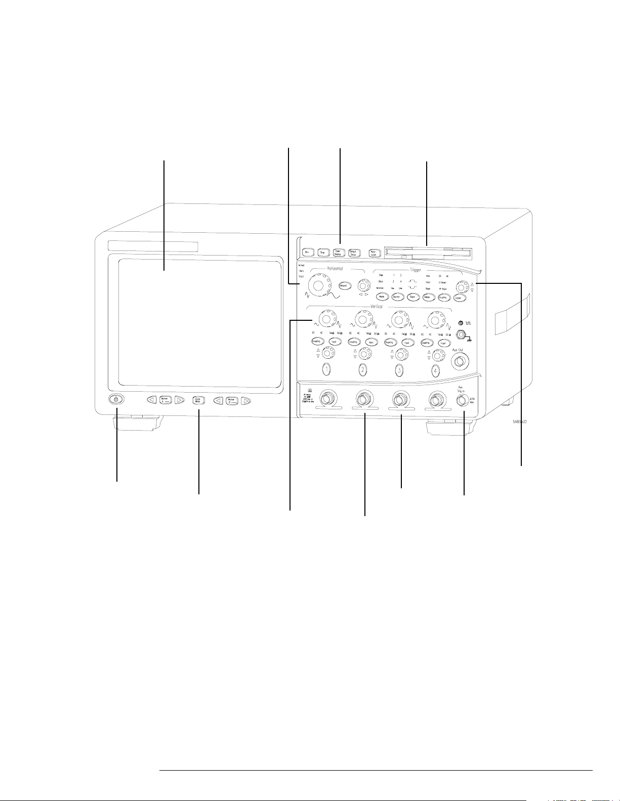
Display and
Graphical
Interface
Horizontal
controls
Acquisition and
general controls
Floppy Disk Drive
Power
Marker and Quick
Measurements
Vertical
Controls
AutoProbe
Interface
Vertical
Inputs
Trigger
Setup
Auxiliary
Trigger Input
iii
Page 4

In This Book
This book provides the service documentation for the Agilent Technologies 54835A/45A/46A
oscilloscope. It is divided into eight chapters.
Chapter 1 provides general information and specifications.
Chapter 2 shows you how to prepare the oscilloscope for use.
Chapter 3 gives performance tests.
Chapter 4 covers calibration and adjustment procedures, how to do them, and how often they
need to be done.
Chapter 5 provides troubleshooting information.
Chapter 6 gives the procedures and techniques for replacing assemblies and other parts.
Chapter 7 includes a list of exchange assemblies and other replaceable parts, part ordering
information, and shipping information.
Chapter 8 briefly covers the internal operation of the oscilloscope.
At the back of the book you will find Safety information, Warranties, and Regulatory information.
iv
Page 5

Contents
Contents 1
1 General Information 1-2
Instruments covered by this service guide 1-2
Accessories supplied 1-3
Options available 1-4
Accessories available 1-5
Specifications & characteristics 1-7
Agilent Technologies 54835A/45A/46A general characteristics 1-14
Recommended test equipment 1-16
2 Preparing for Use 2-2
Setting Up the Oscilloscope 2-3
To inspect the instrument 2-3
To connect power 2-4
To connect the mouse or other pointing device 2-5
To attach the optional trackball 2-5
To connect the keyboard 2-7
To connect to the LAN card 2-7
To connect oscilloscope probes 2-8
To connect a printer 2-9
To connect an external monitor 2-10
To connect the GPIB cable 2-10
To tilt the oscilloscope upward for easier viewing 2-11
To power on the oscilloscope 2-12
To verify basic oscilloscope operation 2-13
To clean the instrument 2-14
To clean the display monitor contrast filter 2-14
3 Testing Performance 3-2
Testing Interval 3-2
Equipment Required 3-2
Self-Test Verification 3-2
Test Record 3-3
Operating Hints 3-3
Specifications 3-3
Performance Test Procedures 3-3
To test the dc calibrator 3-4
To test input resistance 3-6
To test voltage measurement accuracy 3-7
To test offset accuracy 3-11
To test bandwidth 3-13
To test time measurement accuracy 3-16
To test trigger sensitivity 3-23
4 Calibrating and Adjusting 4-2
Equipment Required 4-2
Self Calibration Interval and Hardware Adjustments 4-2
Contents-1
Page 6

Contents
Mainframe Cal Factor Memory Error 4-2
Operating Hints 4-3
Loading Default Oscilloscope Settings 4-3
Loading New Software 4-3
Calibration Procedures 4-3
To check the power supply 4-4
To check the 715 Hz auxiliary output (probe compensation squarewave) 4-6
To check the flat panel display (FPD) 4-7
To run the self calibration 4-10
5 Troubleshooting 5-2
Safety 5-2
Tools Required 5-2
ESD Precautions 5-2
Keystroke Conventions 5-2
Default Setup 5-3
To install the fan safety shield 5-3
To troubleshoot the instrument 5-4
Primary Trouble Isolation 5-6
No Display Trouble Isolation 5-9
Power Supply Trouble Isolation 5-13
To check probe power outputs 5-16
To check the keyboard 5-17
To check the LEDs 5-19
To check the motherboard, CPU, and RAM 5-21
To check the SVGA display board video signals 5-22
To check the backlight inverter voltages 5-23
POST Code Listing (AMI Motherboard only) 5-24
To configure the motherboard jumpers and set up the BIOS 5-29
To troubleshoot the acquisition system 5-49
To troubleshoot attenuator failures 5-56
Software Revisions 5-59
6 Replacing Assemblies 6-2
ESD Precautions 6-2
Tools Required 6-2
To return the instrument to Agilent Technologies for service 6-3
To remove and replace the cover 6-4
To disconnect and connect Mylar flex cables 6-5
To remove and replace the AutoProbe assembly 6-6
To remove and replace the probe power and control assembly 6-8
To remove and replace the backlight inverter board 6-9
To remove and replace the front panel assembly 6-9
To remove and replace the keyboard and flat-panel display assemblies 6-12
To remove and replace the acquisition board assembly 6-14
To remove and replace the LAN interface board 6-15
To remove and replace the GPIB interface board 6-16
To remove and replace the scope interface board and SVGA display board 6-17
To separate the scope interface board and SVGA display board 6-18
To remove and replace the Option 200 sound card 6-19
To remove and replace the hard disk drive 6-20
Contents–2
Page 7

To remove and replace the floppy disk drive 6-21
To remove and replace the motherboard 6-21
To remove and replace the power supply 6-24
To remove and replace the fan 6-25
To remove and replace the CPU 6-26
To remove and replace RAM SIMMs or SDRAM DIMMs 6-27
To remove and replace an attenuator 6-28
To reset the attenuator contact counter 6-30
To remove and replace an acquisition hybrid 6-32
7 Replaceable Parts 7-2
Ordering Replaceable Parts 7-2
Power Cables and Plug Configurations 7-3
Exploded Views 7-4
Replaceable Parts List 7-15
8 Theory of Operation 8-3
Block-Level Theory 8-3
Attenuator Theory 8-7
Acquisition Theory 8-7
Contents
Contents–3
Page 8

1
Instruments covered by this service guide 1-2
Accessories supplied 1-3
Options available 1-4
Accessories available 1-5
Specifications & characteristics 1-7
Agilent Technologies 54835A/45A/46A general characteristics 1-14
Recommended test equipment 1-16
General Information
Page 9

General Information
This chapter of the Agilent Technologies Infiniium Oscilloscope Service Guide gi v es
you general information about the instrument. The following topics are covered in this
chapter.
• Instrument identification
• Options
• Accessories
• Specifications and characteristics
• Test equipment requirements
Instruments covered by this service guide
On the rea r panel of the instrum ent is a se rial number label and a VIN # la bel. The seria l number
is in the form of XX00000000 while the VIN # is in the form of VIN # 0XX. The serial number is
com pose d of two par t s: th e first t wo lett e r s and the first fo ur numbe rs are the seria l p refi x , w h ile
th e l as t f our nu mb ers a re th e su ff ix . T he p re fi x is no rm al ly t he sa me f or al l i den ti ca l o sci ll os co pes
and changes only when a change has been made to the oscilloscope. However, the suffix is
sequentially assigned and is different for each oscilloscope. The contents of this manual applies
to oscilloscopes with serial number prefixes listed on the title page.
An oscilloscope manufactured after the printing of this manual may have a newer serial number
prefix. This newer serial prefix indicates that the oscilloscope may be different from those
described in this manual. The manual for this oscilloscope will be revised as needed. If you have
an oscilloscope with a newer serial prefix, please refer to the Agilent Technologies website and
download a newer manual edition in Adobe Acrobat (pdf) format. The Agilent Technologies
URL is: “www.agilent.com”. It will be necessary to search on a key word such as “Infiniium
Service Guide”, and follow the links.
For additional information on configuration differences see the following sections in this service
guide:
• “To configure the motherboard jumpers and setup the BIOS” in the Troubleshooting section
5 for information on determining:
•which computer configuration is contained in your oscilloscope
•setting up the BIOS correctly for that configuration
•setting the motherboard jumpers if the PC motherboard is changed.
• Replaceable Parts section 7.
This section contains exploded views for the different motherboard configurations, cabling
schemes, and outside hardware versions. The Replaceable Parts List also contains the
assembly part numbers for the different oscilloscope configurations.
Table 1-1
Oscilloscopes Covered by this Service Guide
Model Description
Agilent 54846A Four-channel digitizing oscilloscope with 8 GSa/s sample rate in 2-channel mode, 4
GSa/s sample rate in 4-channel mode, 2.25 GHz bandwidth
Agilent 54845A Four-channel digitizing oscilloscope with 8 GSa/s sample rate in 2-channel mode, 4
GSa/s sample rate in 4-channel mode, 1.5 GHz bandwidth
Agilent 54835A Four-channel digitizing oscilloscope with 4 GSa/s sample rate in 2-channel mode,
2 GSa/s sample rate in 4-channel mode, 1 GHz bandwidth
The oscilloscope can be identified by the product number on the back panel.
1–2
Page 10

Chapter 1: General Information
Accessories supplied
Accessories supplied
The following accessories are supplied.
• Agilent Mouse, Agilent P/N C3751-60201
• Agilent Mouse Pad, Agilent P/N 54810-85903
•1 Keyboard
• (4) Agilent 1161A 10:1 10 M
• Accessory Pouch (Agilent P/N 54810-68701)
• Power cord (see chapter 7, “Replaceable Parts,” for available power cords)
• User's Quick Start Guide
• Programmer’s Guide and Programmer’s Quick Reference
• Agilent Technologies Infiniium Oscilloscope Service Guide for Agilent Models
54835A/45A/46A (this manual)
Ω passive probes
1–3
Page 11

Chapter 1: General Information
Options available
Options available
The following options are available for the Agilent Technologies Infiniium oscilloscope.
Table 1-2
Agilent Technologies Infiniium Oscilloscope Model 54835A/45A/46A Options
Option Number Description
090 Delete standard probes
001 Add 2 standard probes—Agilent 1161A probes for the Agilent 54835A/45A/46A
002 Add 1 Agilent 1162A 1:1 passive probe
003 Add 1 Agilent 1163A 10:1 500 Ω, low-C passive probe
006 Add 1 Agilent 1152A 2.5 GHz, 0.6 pF active probe
007 Add 1 Agilent E2613A, 0.5 mm wedge kit assembly
008 Add 1 Agilent 1153A 200 MHz differential probe
009 Add 1 Agilent 1154A 500 MHz differential probe
010 Add 1 Agilent 1159A 1 GHz differential probe
100 Communication Mask Test Kit
200 VoiceControl Option
1BP MIL-STD-45662A and ANSI/NCSL Z540 calibration with test data
1CM Add 1 Rackmount kit (Agilent E2609A)
UL6 Add 1 Clip-on trackball pointing device (Agilent E2611A)
UL5 Add 1 touchpad pointing device (Agilent E2612A)
W32 3 years calibration service
W34 3 years return standards comp cal service
W50 5 years return repair service (additional 2 years)
W52 5 years return calibrations service
W54 5 years return standards comp cal service
Other options are available. See your Agilent Technologies Sales Representative. You can order
multiple options, or you can order most of these options separately, using the Agilent model
number or part number.
1–4
Page 12

Chapter 1: General Information
Accessories available
Accessories available
The following accessories are available for use with the Agilent Technologies Infiniium
oscilloscope.
Table 1-3
Accessories for the Agilent Technologies Infiniium Oscilloscope Model 54835A/45A/46A
Agilent 1144A 800 MHz Active Probe
Agilent 1144-61604 Power Probe Extender
Agilent 1145A 2-channel 750 MHz SMT active probe
Agilent 1146A Oscilloscope AC/DC Current Probe
Agilent 1152A 2.5 GHz, 10:1, 100 kΩ, 0.6 pF Active Probe
Agilent 1153A 200 MHz Differential Probe
Agilent 1155A 750 MHz 2-Channel, Low-Mass Active Probe
Agilent 1161A Standard probes for the Agilent 54835A/45A/46A
Agilent 1162A 1:1 Passive Probe
Agilent 1163A 10:1 500-Ω, low-C Passive Probe
Agilent 1170A 500 MHz Low-Mass, miniature 10:1 10 M
Agilent 1171A 500 MHz Low-Mass, miniature 10:1 10 M
Agilent 1172A 500 MHz Low-Mass, miniature 20:1 10 M
Agilent 1173A 500 MHz Low-Mass, miniature 20:1 10 MΩ Passive Probe
Agilent 1182A Testmobile
Requires Agilent 1142A power supply—Agilent 1144-61604 probe power extender also
required when using 2 or more Agilent 1144A active probes
Requires Agilent 1142A power supply
Ω Passive Probe
Ω Passive Probe
Ω Passive Probe
Agilent 10020A Resistive Divider Probe Kit
Agilent 10240B BNC Blocking Capacitor
Agilent 10833A GPIB cable, 1 m
Agilent 10833B GPIB cable, 2 m
Agilent 10833C GPIB cable, 4 m
Agilent 10833D GPIB cable, 0.5 m
Agilent 11094B 75Ω Feedthrough Termination
Agilent 34810B Benchlink Oscilloscope Software
Agilent 34398A +
Agilent 34399A
Agilent 54006A 6 GHz, 10:1 (500 Ω) or 20:1 (1 kΩ), .25 pF
Agilent 01144-61604 1:2 probe power fan-out (for use with Agilent 1144A and Agilent 1145A)
Agilent C2950A Parallel printer cable, 2 m
Agilent C2951A Parallel printer cable, 3 m
Agilent E2610A Keyboard
Agilent E2609A Rackmount Kit
Agilent E2611A Clip-on Track Ball Pointing Device
RS-232-C printer cable + adapter kit
1–5
Page 13

Chapter 1: General Information
Accessories available
Agilent E2612A Touchpad Pointing Device
Agilent E2625A Communication Mask Test Kit
Agilent 54810-68703 Service Kit (includes service software and fan safety shield)
Agilent 54801-00601 Fan Safety Shield (clips onto side of chassis with cover removed)
Agilent E2635A Voice Control Retrofit Kit
Agilent E2636A Microphone Replacement
1–6
Page 14

Chapter 1: General Information
Specifications & characteristics
Specifications & characteristics
The following tables list the performance specifications and operating characteristics for the
Agilent Technologies 54835A/45A/46A oscilloscope. Asterisks (*) denotes warranted
specifications, all others are typical. Specifications are valid after a 30 minute warm-up period,
and within
Acquisition
± 5 °C from the self-calibration temperature.
Maximum Sample Rate Real Time Agilent Models
Maximum Effective Sample Rate Equivalent Time 500 GSa/s
Memory Depth 2-channel mode: 65,536 points
4-channel mode: 32,768 points
Memory Depth Modes Auto Optimized for best combination of
Manual Selectable
Sampling Modes Real Time Successive single shot acquisitions.
Equivalent Time Random repetitive sampling (higher
Filters 9-bit Bandwidth Limit filter: BW = (Sample Rate)/20
(Sin x)/x Interpolation: On/Off selectable FIR digital filter. Digital signal
processing adds points between acquired data points to enhance
measurement accuracy and waveform display quality.
BW= Sample Rate/4
54835A — 2-channel mode: 4 GSa/s
54835A — 4-channel mode: 2 GSa/s
54845A — 2-channel mode: 8 GSa/s
54845A — 4-channel mode: 4 GSa/s
54846A — 2-channel mode: 8 GSa/s
54846A — 4-channel mode: 4 GSa/s
Agilent 54835A, Agilent 54845A, and
Agilent 54846A
update rate and display quality.
2-channel mode: from 16 to 65,536
points
4-channel mode: from 16 to 32,768
points
time resolution at fast sweep speeds).
Averaging Selectable from 2 to 4096.
1–7
Page 15

Chapter 1: General Information
Specifications & characteristics
Vertical
Number of Channels 4 (simultaneous acquisition)
Bandwidth Analog Bandwidth (-3dB)* 50Ω: 1.0 GHz — Agilent 54835A
System Bandwidth Agilent 1161A 10:1 passive probe: 500 MHz
Real Time bandwidth* 50Ω:
Rise Time
1
50Ω: 350 ps (Agilent 54835A)
50Ω: 233 ps (Agilent 54845A)
50Ω: 156 ps (Agilent 54846A)
1 MΩ: 700 ps
Sensitivity
2
1 MΩ Coupling: 2 mV/div to 2 V/div
50 Ω Coupling: 2 mV/div to 1 V/div
Input Impedance* 1 MΩ ± 1% (≅12 pf), or 50 Ω ± 1.5%
VSWR (50 Ω) 54835A/45A
dc to 500 MHz: 1.30
500 MHz to 1 GHz: 1.50
1 GHz to 1.5 GHz: 1.75
Input Coupling dc, ac (7 Hz, available in 1 MΩ only)
Maximum Input Voltage 1 MΩ: ± 100 V (dc + ac) [ac<10 kHz], CAT I
rms
, CAT I
Channel-to-channel Isolation
(with channels at equal
sensitivity)
50 Ω: 5 V
54835A/54845A
dc to 100 MHz: 40 dB
100 MHz to 1 GHz: 30 dB
1 GHz to 1.5 GHz: 25 dB
Offset Range Vertical Sensitivity Available Offset
1 MΩ:
2 mV to 104 mV/div
> 104 mV to 2 V/div
50Ω: all
Full-resolution channel
10, 20, 50, 100, 200, 500, 1000 mV/div (plus 2000 mV/div in 1 MΩ)
scales
Dynamic Range ± 8 div from center screen
dc Gain Accuracy
Resolution
2
*2
± 1.00% of full scale at full-resolution channel scale.
Real Time 8 bits (0.4% of full scale), 12 bits with
Equivalent Time 8 bits (0.4% of full scale), 12 bits with
50Ω: 1.5 GHz — Agilent 54845A
50Ω: 2.25 GHz — Agilent 54846A
1 MΩ: 500 MHz (with Agilent 1161A probe)
Agilent 1162A 1:1 passive probe: 25 MHz
Agilent 1163A 10:1, 500 Ω passive probe:
1.5 GHz
Agilent 1152A 2.5 GHz, 0.6 pF active probe:
1.3 GHz (Agilent 54845A)
Agilent 1152A 2.5 GHz, 0.6 pF active probe:
1.0 GHz (Agilent 54835A)
Agilent 1153A 200 MHz differential probe:
200 MHz
Agilent 54835A — 1 GHz (2-channel mode)
Agilent 54835A — 500 MHz (4-c hannel mode)
Agilent 54845A — 1.5 GHz (2-channel mode)
Agilent 54845A — 1.0 GHz (4-channel mode)
Agilent 54846A — 2.25 GHz (2-cha nnel mode)
Agilent 54846A — 1.0 GHz (4-channel mode)
1 MΩ: 500 MHz
54846A
dc to 500 MHz: 1.30
500 MHz to 1 GHz: 1.50
1 GHz to 1.5 GHz: 1.75
1.5 GHz to 2.25 GHz: 2.50
54846A
dc to 100 MHz: 40 dB
100 MHz to 1 GHz: 30 dB
1 GHz to 2.25 GHz: 24 dB
± 4 V
± 40 V
± 12 div
sufficient averaging (0.024% of full scale)
sufficient averaging (0.024% of full scale)
1–8
Page 16

Chapter 1: General Information
Specifications & characteristics
Offset Accuracy*
dc Voltage Measurement
Accuracy*
2
2
± (1.00% of channel offset + 1% of full scale) at full-resolution channel scale.
Dual Cursor ±[(dc gain accuracy)+(resolution)]
Single Cursor ±[(dc gain accuracy)
+(offset accuracy)+(resolution/2)]
AutoProbe Interface AutoProbe is an intelligent communication and power link between compatible
probes and Infiniium scopes. AutoProbe completely configures the scope for the
attached probe . For instance, it identifies t he probe type and sets up the pro per input
impedance, attenuation ratio, probe power and offset range, as needed.
Horizontal
Main Time Base Range 100 ps/div to 20 s/div
Horizontal Position Range pre-trigger 0 to -1 s or one full screen width,
post-trigger 0 to 1 s or one full screen width,
Delayed Sweep Range 1 ps/div to current main time base setting.
Delayed Sweep Delay Range Within main time base acquisition record.
Resolution 2 ps
Timebase Accuracy 70 ppm (.007%)
∆t Accuracy* Real Time mode
4
whichever is larger.
whichever is larger.
±[(.007%)(∆t)+(0.2)(sample period)]
Equivalent Time mode ±[(.007%)(∆t)+(full scale/
(2 × memory depth)) + 30 ps]
(Example: for ≥ 16 avgs, 9 ns signal,
1 ns/div, 1 channel, then accuracy =
±[(.007%)(9 ns)+(10 ns/(2 × 65,536)) + 30
ps] = 31 ps)
1–9
Page 17

Chapter 1: General Information
Specifications & characteristics
Trigger
Sensitivity*
2
Internal dc to 100 MHz: 0.5 div
100 MHz to 500 MHz: 1.0 div
500 MHz to 1 GHz: 1.5 div
Auxiliary dc to 500 MHz: 300 mV
Maximum Input Voltage* Auxiliary ±15 V, CAT I
Minimum Pulse Width
(internal, external)
Level Range Internal ±8 div from center screen
Sweep Modes Auto, triggered, single
Trigger Coupling dc, ac (7 Hz), low frequency reject (50 kHz), high frequency reject (50 kHz).
Trigger Holdoff Range 60 ns - 320 ms
Trigger Modes Edge, Glitch, Pattern, State, Delay by Time, Delay by Events, Violation (
Glitch Select positive or negative polarity, width. Captures glitches as narrow as 500 ps.
Pattern Select inputs as High, Low or X (don’t care) to create pattern. Trigger when
State Select one channel as clock, specify other inputs as High, Low or X.
Delay by Time Time: 30 ns to 160 ms. The trigger is qualified by an edge. After the delay, a
Delay by Events Events: 1 to 16,000, 000 rising or falling edges. The trigger is qualified by an edg e.
500 ps at > 1.0 div
Auxiliary ±5 V
Setup/Hold Time, Pulse Width, Transition), Video, Line.
pattern is entered, exited, present > t, present < t, or present over a range of
time. Captures patterns as narrow as 500 ps.
Logic Type: AND or NAND
rising/falling edge on any one selected input will generate the trigger.
After the delay, a rising/falling edge on any one selec ted input will generate the
trigger.
pp
Violation Trigger Setup/Hold Modes: Setup, Hold or Setup and Hold.
Pulse Width Triggers on pulse width >t, or <t.
Transition Select Rise Time or Fall Time,
Accuracy (time) for glitch, pulse
width, and time-qualified pattern
Video Triggering 525 lines/60 Hz (NTSC), 625 lines/50 Hz (PAL), 875 lines/60 Hz. Trigger on Field 1
1.5 ns - 20 ns: ±(20% setting + 500 ps)
20 ns - 160 ms: ±(3% setting + 2 ns)
or Field 2, any line. User defined triggering: User can specify sync pulse level,
width and polarity, edge number.
Select Clock, Thresholds, setup and/or
hold time.
Captures pulses as narrow as 500 ps.
present > t or present < t, thresholds.
1–10
Page 18

Display
Chapter 1: General Information
Specifications & characteristics
Display 8.4-inch diagonal color active matrix LCD module incorporating amorphous
silicon TFTs.
Active Display Area 171 mm x 128 mm (21,888 sq. mm)
Waveform Viewing Area 104 mm x 159 mm (16,536 sq. mm) in Full screen mode
(graphical user interface off)
Display Resolution 640 pixels horizontally x 480 pixels vertically
Waveform Colors Select from 100 hues, 0-100% saturation and 0-100% luminosity.
Dual Intensity Infinite Persistence Previous sweeps are stored in half bright display and most recent sweep in full
bright. This allows easy differentiation of current and historic information.
Waveform Overlap When two waveforms overlap, a third color distinguishes the overlap area.
Full screen mode On/Off selectable.
Connect-the-dots On/Off selectable.
Persistence Minimum, Variable (100 ms to 40 s), Infinite. Up to 6 levels of grey scale.
Graticule On/Off (Grid or Frame).
Grid Intensity 0 to 100%
Display Update Rate
(for instruments equipped with
AMD-K6-2 400 MHz processor)
Measurement Conditions Real Time sampling mode, minimum
persistence, triggered sweep, no
interpolation, markers off, math off,
connect the dots off, 1 channel
acquisition, 50 ns/div, statistics off.
512 point record (2 GSa/s) Waveforms/sec: > 2,100
V
Measurements/sec: > 130
pp
Measurements
, V
Automatic Parametrics 33 automatic measurements: V
Preshoot, Overshoot, V
upper
, V
pp
middle
min
, V
, V
max ,Vavg
lower
Frequency, Positive Width, Negative Width, Duty Cycle, Delta Time, T
FFT Frequency, FFT Magnitude, FFT Delta Frequency, FFT Delta Magnitude, Eye
Height, Eye Width, Jitter, Crossing %, Q-factor, Duty Cycle Distortion.
Over GPIB only: VTime, TVolts.
Threshold Definition Selectable 10%, 50%, 90% or 20%, 50%, 80% or Custom (% or absolute voltage).
Top-Base Definition Standard or Custom (in absolute voltage).
Statistics On/Off selectable. Current measurement, mean, and standard deviation
Measurement Toolbar 16 Drag and Drop automatic measurement icons.
QuickMeas Activates 4 preselected automatic measurements.
Markers Modes Manual Markers, Track Waveform Data, Track Measurements.
Waveform Math 4 function waveforms f1-f4. Select from Add, Subtract, Multiply, Divide, Invert,
Magnify, Vs, Min, Max, Integral, Differentiate, FFT Magnitude.
, V
, V
, V
amptd
base
top
, V
, Rise Time, Fall Time, Period,
max
, T
rms
min
,
,
1–11
Page 19

Chapter 1: General Information
Specifications & characteristics
FFT
Frequency Range
Freq. Accuracy (1/2 frequency resolution)+(7x10
Amplitude Display Power in dBm
5
Agilent 54835A — 2-channel mode: dc to 2 GHz (Sample rate/2)
Agilent 54835A — 4-channel mode: dc to 1 GHz (Sample rate/2)
Agilent 54845A — 2-channel mode: dc to 4 GHz (Sample rate/2)
Agilent 54845A — 4-channel mode: dc to 2 GHz (Sample rate/2)
Agilent 54846A — 2-channel mode: dc to 4 GHz (Sample rate/2)
Agilent 54846A — 4-channel mode: dc to 2 GHz (Sample rate/2)
-5
)(signal frequency)
Signal-to-noise ratio 70 dB at 32K memory depth. Noise floor varies with memory depth and with
averaging.
Window Modes Hanning, Flattop, Rectangular.
Computer System/ Storage
CPU AMD-K5
Disk Drive 1.4 GByte, 2.1 GByte, or higher
File types Waveforms Internal Y values; X and Y values in ASCII
Mouse Standard mouse supplied—supports any Microsoft
Operating System Microsoft Windows 95 or Microsoft Windows 98
Waveform Memories 4 nonvolatile waveform reference memories.
™
PR133 Microprocessor
(instrument serial numbers US37349999 and below) or
AMD-K6™ 200 MHz Microprocessor or
AMD-K6/300
™
or AMD-K6-2/300™ 300 MHz Microprocessor
Store and recall setups, waveforms, and
internal hard drive depending upon
the vintage. Storage capacity is
limited only by disk space. 3.5", 1.44
Mbyte MS-DOS
™
-compatible high
store screen images to both the hard drive
and the floppy drive.
density floppy disk drive or LS-120
MS-DOS 120 MByte floppy disk
drive.
or Microsoft Excel formats.
Images BMP, EPS, GIF, PCX, PS (Postscript), TIF.
®
mouse compatible pointing
device, serial or PS/2.
I/O
LAN Enables data/setup file transfers and use of network printers; supports popular
GPIB Fully programmable, complies with IEEE 488.2.
RS-232 (serial) 2 ports: COM1, COM2. Printer and pointing device support.
Centronics Printer port.
USB Two pinheads link with Universal Serial Bus connectors (USB1 and USB2)
Printers and Plotters Supports all pr inters and plotters compat ible with Microsoft Windo ws95
PS/2 port For PS/2 mouse.
Keyboard port For optional keyboard.
network operating systems including Novell NetWare, Microsoft, Banyan VINES,
SCO UNIX and IBM; 10 Mbps operation that complies with IEEE 802.3 Ethernet and
ISO/IEC 8802-3 Ethernet standards; TCP/IP protocol; RJ-45 connector.
peripheral devices via either a dual-port USB cable or a single-port USB cable on
some configurations with serial prefixes US39480000 and above.
®
. Includes
but is not limited to Hewlett-Packard Deskjet and Laserjet printers. GPIB devices
not supported.
1–12
Page 20

Video Output 15-pin VGA, full color.
Notes
1 Rise Time figures are calculated from: tr=.35/Bandwidth.
Chapter 1: General Information
Specifications & characteristics
2 Magnification is used below the 10 mV/div range and between the major attenuation settings. Full scale
3N/A
4 For bandwidth limited signals, tr >=1.4 x sample interval.
5 FFT amplitude readings are affected by input amplifier roll-off (-3 dB, with amplitude decreasing as
is defined as the major attenuator setting over an intermediate setting.
(Major settings for 50Ω: 10, 20, 50, 100, 200, 500, 1000 mV
Major settings for 1 MΩ: all as for 50Ω plus 2 V)
frequency increases above 500 MHz in 1 MΩ, 2.25 GHz for Agilent 54846A, 1.5 GHz in 50 Ω for Agilent 54845A,
1 GHz in 50Ω for Agilent 54835A).
CAT I and CAT II Definitions
Installation category (overvoltage category) I: Signal level, special equipment or parts of
equipment, telecommunication, electronic, etc., with smaller transient overvoltages than
installation category (overvoltage category) II.
Installation category (overvoltage category) II: Local level, appliances, portable equipment etc.,
with smaller transient overvoltages than installation category (overvoltage category) III.
1–13
Page 21

Chapter 1: General Information
Agilent Technologies 54835A/45A/46A general characteristics
Agilent Technologies 54835A/45A/46A general characteristics
The Infiniium oscilloscopes meet the Agilent Technologies Environmental Specification (section
750) for class B-1 products with exceptions as described for temperature.
General Characteristics
Environmental Temperature Operating: 10°C to +40°C
Humidity Operating: Up to 95% relative humidity
Altitude Operating: Up to 4 600 meters
Vibration Operating: Random vibration 5-500 Hz,
Physical Size (excluding handle) Height: 216 mm
Weight Net: approximately 12 kg
Power Line voltage selection None, PFC (Power Factor Correction)
Line voltage range 100-240VAC, ± 10% CAT II
Line frequency 47 to 440 Hz
Nonoperating: –40°C to 70°C
Indoor use only
(noncondensing) at +40°C
Nonoperating: Up to 90% relative
humidity at +65°C
Nonoperating: Up to 15 300 meters
10 minutes per axis, 0.3g (rms)
Nonoperating: Random vibration 5-500
Hz, 10 minutes per axis, 2.41g (rms)
Resonant search 5-500 Hz, swept sine,
1 octave/minute sweep rate, (0.75g),
5-minute resonant dwell at 4
resonances per axis.
Width: 437 mm
Depth: 440 mm
Shipping: approximately 15 kg
Maximum power consumption 390 W
Safety Meets IEC1010-1 +A1, CSA certified to C22.2 No. 1010. 1, Self certified to UL 3111.
1–14
Page 22

Chapter 1: General Information
Agilent Technologies 54835A/45A/46A general characteristics
1–15
Page 23

Chapter 1: General Information
Recommended test equipment
Recommended test equipment
The following table is a list of the test equipment required to test performance, calibrate and
adjust, and troubleshoot this instrument. The table indicates the critical specification of the test
equipment and for which procedure the equipment is necessary. Equipment other than the
recommended model may be used if it satisfies the critical specification listed in the table.
Recommended Test Equipment
Equipment Required Critical Specifications Recommended Model Use *
Signal Generator 1 - 2.25 GHz, sine wave, amplitude 30 - 200
RF Amplifier 22 dB gain at 10 MHz, 1.3 GHz bandwidth Agilent 8447D/F P
Power Meter/Power
Sensor
DMM 6 1/2 digit (0.1 mV) resolution, dcV accuracy
Power Supply 7 mV - 30 V dc, 0.1 mV accuracy and resolution Agilent 6114A P
Power Splitter 50 Ω type N, outputs differ by <0.15 dB Agilent 11667A P
Probe No substitute Agilent 1161A P
Probe Tip Adapter 1160 series to BNC Agilent 5063-2143 P
Oscilloscope General-purpose Agilent 54622A P, T
Blocking Capacitor 0.18 µF Agilent 10240B P
Cable Type N (m)(m) - 3 foot Agilent 11500A or B P
Cable (2) BNC - 3 foot Agilent 10503A P, A, T
Cable (3) BNC - 9 inch Agilent 10502A P, A, T
Adapter N (m) to BNC (m) Agilent 1250-0082 P
Adapter N (m) to BNC (f) Agilent 1250-0780 P
Adapter N (f) to BNC (m) Agilent 1250-0077 A
Adapter (2) BNC tee (m)(f)(f) Agilent 1250-0781 P, T
Adapter BNC (f)(f) Agilent 1250-0080 T
Adapter (2) BNC (f) to dual banana (m) Agilent 1251-2277 P
Termination BNC connectors 50 Ω Agilent 10100C P
Shorting cap BNC Agilent 1250-0774 P
Resistor (2) 5 Ω, 5 W Agilent 0812-0047 T
Video monitor Accepts VGA-standard video signals T
Keyboard PC-compatible, AT 5-pin connector Agilent E2610A T
Mouse PS/2 compatible Agilent C3751-60201 P, T
POST Card Power-on self test card compatible with PC-
Fan Safety Shield Clips onto side of chassis with cover removed Agilent 54801-00601 A, T
Service software No substitution Agilent 54810-68700 T
Note: the Fan Safety Shield and Service software are part of the Service Kit, Agilent P/N 54810-68703.
* P = Performance Tests, A = Adjustments, T = Troubleshooting
, time base accuracy 0.25 ppm
mV
rms
1 - 500 MHz, -70 dBm to +44 dBm, ±3% accuracy Agilent EPM-
8 ppm/year, 4-wire resistance acc. ±0.25%
compatible systems
Agilent 8664A P
P
441A/Agilent 8482A
Agilent 34401A P, A, T
T
1–16
Page 24

2
Setting Up the Oscilloscope 2-3
To inspect the instrument 2-3
To connect power 2-4
To connect the mouse or other pointing device 2-5
To attach the optional trackball 2-5
To connect the keyboard 2-7
To connect to the LAN card 2-7
To connect oscilloscope probes 2-8
To connect a printer 2-9
To connect an external monitor 2-10
To connect the GPIB cable 2-10
To tilt the oscilloscope upward for easier viewing 2-11
To power on the oscilloscope 2-12
To verify basic oscilloscope operation 2-13
To clean the instrument 2-14
To clean the display monitor contrast filter 2-14
Preparing for Use
Page 25

Preparing for Use
This chapter shows you how to prepare the Agilent Technologies 54835A/45A/46A
oscilloscopes for use. The following areas are covered in this section.
•Inspection
•Setup
• Connecting a signal
•Cleaning
Following instrument setup is a brief section covering oscilloscope operation. If you are
unfamiliar with this oscilloscope's operation, refer to the User’s Quick Start Guide. The
topics covered include:
• Using the front panel
• Using the graphical interface
• Starting and stopping acquisition
• Adjusting oscilloscope configuration
• Making measurements
The Infiniium Oscilloscope is designed to make it easy for you to use a high-performance
digitizing oscilloscope.
• The familiar front-panel oscilloscope interface with knobs and buttons is optimized
for the most common kinds of troubleshooting tasks and basic measurements.
• The graphical interface with menus, windows, dialogs, and toolbars provides easy
logical access to dozens of configuration and analysis tools, making it easy for you to
set up and make the most complex measurements.
2–2
Page 26

Chapter 2: Preparing for Use
To inspect the instrument
Setting Up the Oscilloscope
This section will help you get the instrument ready to use. Included are procedures for:
•Inspection
•Connecting power
• Connecting probes and accessories
• Connecting peripherals
• Verifying basic operation
•Cleaning
To inspect the instrument
❏ Inspect the shipping container for damage.
Keep a damaged shipping container or cushioning material until the contents of the shipment
have been checked for completeness and the instrument has been checked mechanically and
electrically.
❏ Check the accessories.
Accessories supplied are listed in chapter 1 of this service guide.
• If the contents are incomplete or damaged notify your Agilent Technologies Sales Office.
❏ Inspect the instrument.
• If ther e is mec hanical damage or defect, or if th e instrument does not operate properly or pa ss
performance tests, notify your Agilent Technologies Sales Office.
• If the shipping container is damaged, or the cushioning materials show signs of stress, notify
the carrier as well as your Agilent Technologies Sales Office. Keep the shipping materials for
the carrier's inspection. The Agilent Technologies office will arrange for repair or replacement
at Agilent Technologies' option without waiting for claim settlement.
2–3
Page 27
Chapter 2: Preparing for Use
To connect power
To connect power
The instrument Power Factor Correction (PFC) circuitry in the oscilloscope’s power supply
operates over a line voltage in the range of 100 to 240 Vac
to the input voltage and frequency). Line frequency must be in the range 47 to 440 Hz. Power
consumption is 390W maximum.
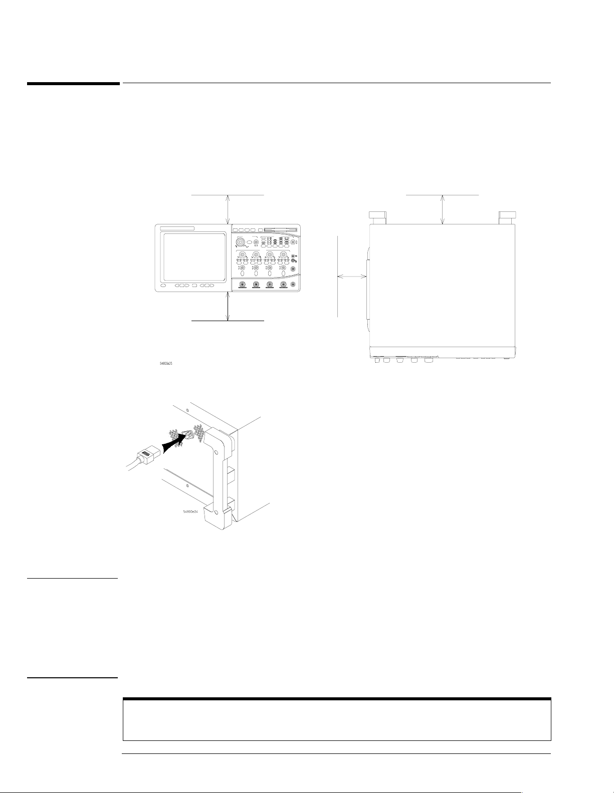
1
Position the instrument where it will have sufficient clearance for airflow around the
top, back, and sides.
±10% (the power supply is autoranging
Minimum 0 mm
Minimum 15.9 mm (maintain ed by feet; however,
do not place on soft surfaces that will impede
airflow)
Airflow requirements
Agilent 54835A/45A/46A – 250
2 Connect the power cord to the rear of the oscilloscope, then to a suitable ac voltage
source.
Minimum 38.1 mm
Minimum
15.9 mm
both
sides
The line cord provided is matched by Agilent Technologies to the country of origin of order.
Ensure that you have the correct line cord. See “Power Cables and Plug Configurations” in
chapter 7.
WARNING SHOCK HAZARD!
BEFORE YOU CONNECT THIS INSTRUMENT TO MAINS POWER OR LIVE MEASURING
CIRCUITS, you must provide a protective earth ground. Failure to provide a protective earth
ground could result in a shock hazard if there is a failure in this instrument or equipment
connected to it.
The mains plug must be inserted in a socket outlet provided with a protective earth contact.
Do not use an extension cord (power cable) without a protective conductor (grounding).
Grounding one conductor of a two-conductor outlet does not provide an instrument ground.
A Three-wire Power Cable is Provided
This instrument is provided with a three-wire power cable. When connected to an appropriate ac power
outlet, this cable grounds the instrument cabinet.
2–4
Page 28
Chapter 2: Preparing for Use
To connect the mouse or other pointing device
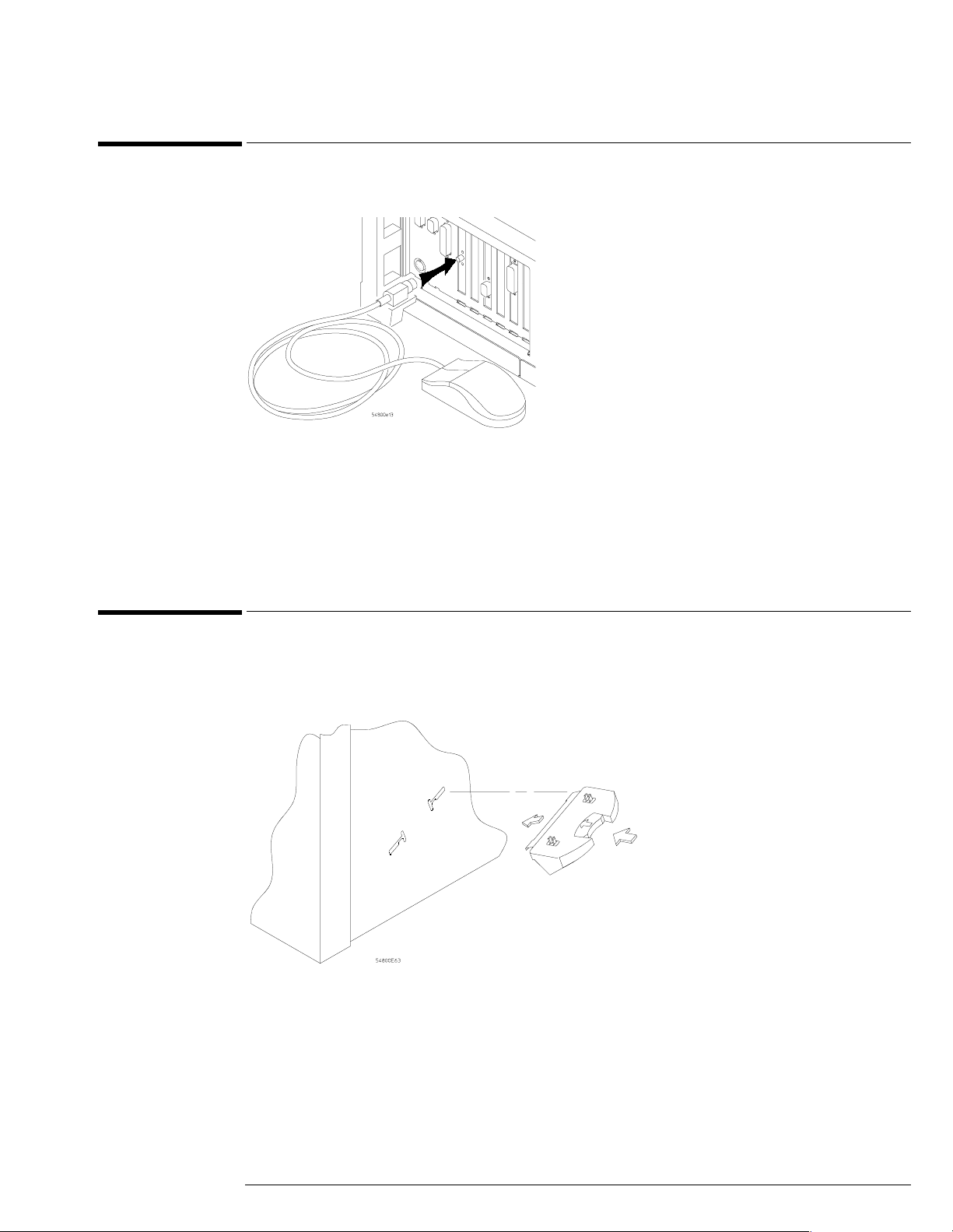
To connect the mouse or other pointing device
• Plug the mouse into the matching connector on the back panel of the oscilloscope.
The mouse is included with the oscilloscope, but using it is optional. While you can operate many
oscilloscope functions with only the front-panel keys and knobs, you will need the mouse to
access advanced oscilloscope functions through the graphical interface, or to find out more about
the oscilloscope through the built-in information system.
The optional touchpad pointing device connects in exactly the same way as the mouse.
The supplied mousepad provides the correct surface for smooth mouse operation. To modify the
mouse configuration, see the User’s Quick Start Guide.
To attach the optional trackball
1 Push in the latch on the trackball baseplate to extend the metal tabs. Insert the lower
tab into the frontmost slot on the side of the oscilloscope. You can only install the
trackball on the right side of the oscilloscope.
2–5
Page 29
Chapter 2: Preparing for Use
To attach the optional trackball
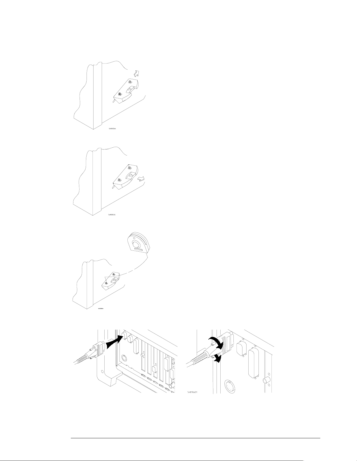
While holding the latch in, slide the metal tabs up and to the rear of the oscilloscope
2
until they fully engage the slot.
3 Release the latch. The trackball baseplate should now be secure against the side of the
oscilloscope.
4 Snap the trackball assembly onto the pins of the baseplate. The trackball and buttons
should face up and toward the front of the oscilloscope.
5 Connect the 9-pin “D” connector on the trackball cable to the COM1 port on the back
panel. Tighten the retaining screws.
For information on changing the trackball settings, see the User’s Quick Start Guide.
2–6
Page 30
Chapter 2: Preparing for Use
To connect the keyboard
To connect the keyboard
• Plug the keyboard cable into the matching connector on the back panel of the
oscilloscope.
The keyboard simplifies access to some oscilloscope functions, such as entering file names when
you store waveforms and setups to the disk. If you need to free desk space, place the keyboard
on top of the instrument. Do not stack other objects on the keyboard; this will cause self-test
failures on power-on.
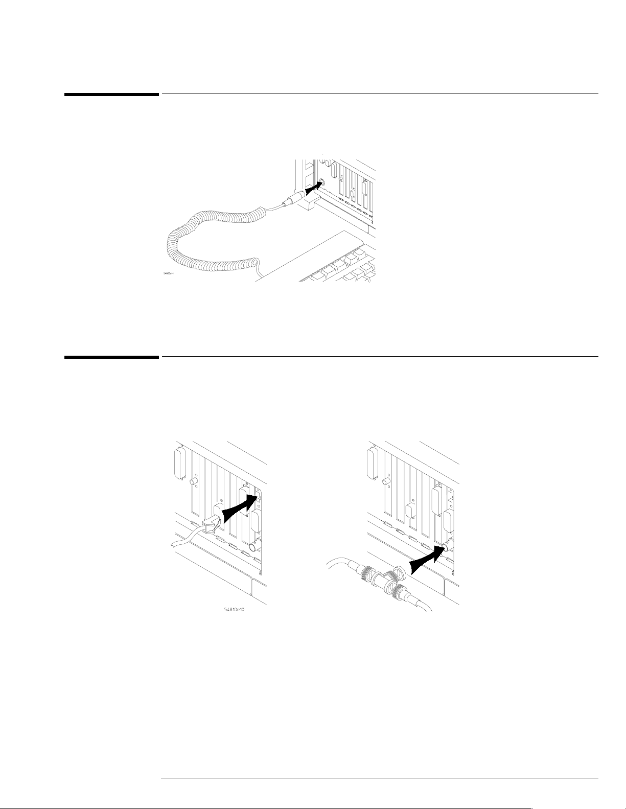
To connect to the LAN card
• Connect your LAN cable to one of the connectors on the LAN card. Make sure the
connection is secure. Two connections are possible on the LAN card: the RJ-45
connection and a BNC connection. Units equipped with 10/100Base-T LAN cards have
an RJ-45 connector only.
RJ-45 Connection
Each Infiniium Oscilloscope now ships with a LAN card installed. If you want a LAN connection,
but have an older Infiniium Oscilloscope model that does not have a LAN card installed, contact
your Agilent Technologies Sales and Service Office. An Agilent Technologies LAN Card
Installation Kit with instructions is available from Agilent Technologies, and describes how to
add a LAN card to your Infiniium Oscilloscope. After you have connected to the LAN card, you
must set up the network as described in the User’s Quick Start Guide.
BNC Connection
2–7
Page 31

Chapter 2: Preparing for Use
To connect oscilloscope probes
To connect oscilloscope probes
1 Attach the probe BNC connector to the desired oscilloscope channel or trigger input.
Push it straight on until it latches into place.
2 Connect the probe to the circuit of interest using grabbers or other probing aids.
3 To disconnect the probe, push the small latch on top of the probe connector to the left,
then pull the connector body away from the front panel of the oscilloscope without
twisting it.
CAUTION AVOID DAMAGE TO THE PROBE CONNECTOR!
Do not a ttempt to t wist the sn ap-o n prob es on or off the oscil loscope’s B NC connector. T wisting
the probe connector body will damage it.
CAUTION DO NOT EXCEED THE MAXIMUM INPUT VOLTAGE!
Do not ex ceed th e maxim u m in put vo ltage ratin g of th e osci llosc ope in puts! The max i m u m input
voltage for 50(dc+ac) [ac < 10 kHz], CAT I. (Probes may have different ratings. See the probe documentation.)
Ω inputs is 5 V
, CAT I. The maximum input voltage for 1 MΩ inputs is ±100V
rms
2–8
Page 32

Chapter 2: Preparing for Use
To connect a printer
To connect a printer
If you have a parallel (Centronics) printer, you will need a parallel printer cable, such as an
Agilent C2950A (2 m) or Agilent C2951A (3 m) cable. Go to step 1.
If you have a serial printer, you will need a 9-pin to 25-pin serial printer cable, such as an
Agilent 34398A cable, plus the Agilent 34399A adapter kit. Some printers may require other cable
configurations, but the oscilloscope has a 9-pin serial connector. Go to step 4.
1
Attach the 25-pin small “D” connector to the printer output connector on the rear of
the oscilloscope. Tighten the thumbscrews to secure the cable.
2 Attach the larger 36-pin “D” connector to the printer. Latch the wire bails into the tabs
on each side of the connector.
3 Set the printer configuration to use the “Centronics” or “Parallel” interface, if
necessary. Refer to the User’s Quick Start Guide for software installation instructions.
See the documentation for your printer if you have questions about configuring the printer to
use the parallel interface.
4
Connect the 9-pin “D” connector of the serial printer cable to the serial output port on
the rear panel of the oscilloscope. Tighten the thumbscrews to secure the cable.
2–9
Page 33

Chapter 2: Preparing for Use
To connect an external monitor
Attach the 25-pin “D” connector to the serial input port of the printer. Tighten the
5
thumbscrews to secure the cable.
6 Set the printer configuration to use the serial interface. Refer to the User’s Quick Start
Guide for software installation instructions.
See the documentation for your printer if you have questions about configuring the printer to
use the serial interface.
To connect an external monitor
You can connect a VGA-compatible monitor to the Infiniium oscilloscope to provide a larger
viewing area.
• Connect the monitor cable to the display board video connector at the rear panel of the
oscilloscope. Tighten the retaining screws.
To connect the GPIB cable
• Attach the GPIB connector to the GPIB interface card connector at the rear of the
oscilloscope. Tighten the thumbscrews on the connector.
2–10
Page 34

Chapter 2: Preparing for Use
To tilt the oscilloscope upward for easier viewing
To tilt the oscilloscope upward for easier viewing
• If your oscilloscope has front feet with individual wire bails, lift up the front of the
oscilloscope, grasp one of the wire bails under the front corner, and pull it down and
forward until it latches into place. Repeat for the other wire bail.
• If your oscilloscope has front feet with a wire bail between the two feet, lift up the front
of the oscilloscope, grasp the bail near the center, and pull it down and forward until it
latches into place.
2–11
Page 35

Chapter 2: Preparing for Use
To power on the oscilloscope
To power on the oscilloscope
• Depress the power switch at the lower left-hand corner of the oscilloscope front panel.
After a short initialization period, the oscilloscope display appears. The oscilloscope is ready to
use.
Hook up all cables and accessories before applying power. You can connect and disconnect
probes while the oscilloscope is powered-on.
You Can Configure the Backlight Saver
The oscilloscope display has a backlight saver that turns off the backlight when there has been no
interface activity for a pre-determined period. The default time is 8 hours and is configurable through the
Display Setup dialog in the graphical interface. You can turn the display on by moving the mouse, typing
on the optional keyboard, pressing a front-panel key, or turning a front-panel knob.
2–12
Page 36

Chapter 2: Preparing for Use
To verify basic oscilloscope operation
To verify basic oscilloscope operation
1 Connect an oscilloscope probe to channel 1.
2 Attach the probe to the calibration output on the front panel of the oscilloscope.
Use a probe grabber tip so you do not need to hold the probe. The calibration output is marked
with a square wave symbol.
Calibration
Output
3
Press the Default Setup key on the front panel.
The display will pause momentarily while the oscilloscope is configured to its default settings.
4 Press the Autoscale key on the front panel.
The display will pause momentarily while the oscilloscope adjusts the sweep speed and vertical
scale. You s houl d the n see a squarewa ve with pe ak-to-peak amp litu de ap proximate ly 5 d ivisions
and a period of almost 3 divisions. If you do not see the waveform, ensure your power source is
adequate, the oscilloscope is properly powered-on, and the probe is connected securely to the
front-panel channel input BNC and to the probe calibration output.
5
Move the mouse pointer to the graphical interface enable button and click once.
The graphical interface enable button is in the upper-right corner of the display.
6 Move the mouse around the mouse pad and verify that the pointer follows on the
screen.
If the pointer does not move, ensure that the mouse is properly connected, that you have clicked
the correct button to enable the graphical interface, and that the mouse is on a medi um-fr iction
surface such as the mouse pad supplied with the oscilloscope.
With the mouse pointer on
the right-hand button, click
the mouse to enable the
graphical interface
Graphical Interface Enable Button
2–13
Page 37

Chapter 2: Preparing for Use
To clean the instrument
To clean the instrument
• Clean the oscilloscope with a soft cloth dampened with a mild soap and water solution.
CAUTION BE CAREFUL TO AVOID DAMAGING COMPONENTS!
Do not use too much liquid when cleaning the oscilloscope. Water can enter the front panel
keyboard, damaging sensitive electronic components.
To clean the display monitor contrast filter
• Clean the display monitor contrast filter using glass cleaner and lens tissue or a soft cloth.
2–14
Page 38

3
Testing Interval 3-2
Equipment Required 3-2
Self-Test Verification 3-2
Test Record 3-3
Operating Hints 3-3
Specifications 3-3
Performance Test Procedures 3-3
To test the dc calibrator 3-4
Procedure 3-4
To test input resistance 3-6
Procedure 3-6
To test voltage measurement accuracy 3-7
Procedure 3-7
To test offset accuracy 3-11
Procedure 3-11
To test bandwidth 3-13
Equivalent Time Test 3-13
Real Time Test 3-15
1 M
Ω, 500 MHz Test 3-15
To test time measurement accuracy 3-16
Equivalent Time Mode Procedure 3-16
Real-Time Mode Procedure 3-21
To test trigger sensitivity 3-23
Internal Trigger Test 3-23
Procedure—Auxiliary Trigger Test 3-25
Testing Performance
Page 39

Testing Performance
The procedures in this section test measurement performance using Performance
Specifications given in chapter 1 as performance standards. Specifications applicable to
individual tests are noted at the test for reference.
Testing Interval
The performance test procedures may be performed for incoming inspection of the
instrument and should be performed periodically thereafter to ensure and maintain peak
performance. The recommended test interval is yearly or every 2,000 hours of operation.
Test Interval Dependencies
The test interval depends on frequency and severity of use and the environmental conditions under which
the instrument is used. In recording test results, you may find that the test interval could be shortened or
lengthened; however, such a decision should be based on substantial quantitative data.
See Also Chapter 4, “Calibrating and Adjusting,” for information about the calibration cycle.
Equipment Required
A complete list of equipment required for the performance tests is in the Recommended
Test Equipment table in chapter 1. Equipment required for individual tests is listed in
the test. Any equipment satisfying the critical specifications listed may be substituted
for the recommended model. The procedures are based on the model or part number
recommended.
Self-Test Verification
To verify system operation with high confidence, without the test equipment and time
required for performance tests, perform the self-tests. These internal tests verify many
functions of the oscilloscope.
To run the self-tests, enable the graphical interface, then select Self Test from the
Utilities menu. The Self Test drop down list box allows you to select Scope Self Tests,
Key and Knob Test, or LED Test. A message is displayed with the instruction to remove
all inputs to the instrument. During execution of the self-tests, the oscilloscope displays
diagnostic messages indicating the status of each test.
If one of the self-tests fails,
diagnostic code is displayed. This code is used by factory service personnel when
troubleshooting the main assembly. Failure of a self-test indicates an assembly failure.
The assembly must be replaced before y ou attempt performance verificat ion. For more
troubleshooting information, refer to chapter 5, “Troubleshooting.”
FAILED is displayed rather than PASSED, and a 16-bit
3–2
Page 40

Chapter 3: Testing Performance
Test Record
You can record the results of the performance tests in the Performance Test Record
provide d at th e e n d of t h is cha p ter. T h e Perform a nce Te s t Reco r d lists t h e perf o rmanc e
tests and provides an area to mark test results. You can use the results recorded at
incoming inspection for later comparisons during periodic maintenance,
troubleshooting, and after repairs or adjustments.
Operating Hints
Some knowledge of operating the oscilloscope is helpful; however, these procedures are
written so that little experience is necessary. The following two hints will speed progress
of the testing.
Clear Display
When using many averages, it often takes awhile for a waveform display to stabilize after
a change. When a control on the oscilloscope is changed, averaging automatically
restarts. When just the input signal is changed, the instrument must average new data
with the old so it takes longer for the waveform to stabilize.
Press the Clear Display key while changing input signals. The instrument will restart
averaging and give a quick indication of the result of the signal change.
Averaging
Averaging is used to assure a stable signal for measurements. It is not necessary to wait
for com plete stability of the signal (averagi ng com plete), as long a s the m easurement is
well within the limits of the test.
Specifications
The specifications that apply to a particular test are given with the test procedure. The
specification as given with the test may be abbreviated for clarity. In case of any
questions, refer to the complete specifications and characteristics in chapter 1, “General
Information.”
Performance Test Procedures
Performance test procedures start with the next paragraph. Procedures may be done
individually and in any order.
Let the Instrument Warm Up Before Testing
Allow the instrument to warm up for at least 30 minutes prior to beginning performance tests. Failure to
allow warm-up may cause the instrument to fail tests.
3–3
Page 41

Chapter 3: Testing Performance
To test the dc calibrator
To test the dc calibrator
The Aux Out BNC on the front panel is used for self-calibration and probe calibration. Though
calibrator accuracy is not specified in the performance specifications, it must be within limits in
order to provide accurate self-calibration.
Figure 3-1
Test Limits: -2.5 v to +2.5 v, Accuracy
±0.2% of delta voltage output
Equipment Required
Equipment Critical Specifications Recommended Model/Part
Digital Multimeter 0.1 mV resolution, better than 0.1 % accuracy Agilent 34401A
Cable BNC Agilent 10503A
Adapter BNC (f) to banana (m) Agilent 1251-2277
Procedure
1
Connect the multimeter to the front panel Aux Out BNC.
Use the BNC cable and the BNC to banana plug adapter.
2 Enable the graphical interface.
Use the mouse t o click on th e bu tton in t h e upper ri ght-ha n d corner of the d ispla y . S ee figur e 3-1.
Click the mouse with the
pointer on the right-hand
button to enable the
graphical interface
Enabling the graphical interface
3 Press Default Setup to set the oscilloscope to default conditions.
4 Select Calibration from the Utilities menu.
5 Select DC from the Aux Output drop-down list box.
See figure 3-2.
3–4
Page 42

Figure 3-2
Set Aux Output to DC
Set the output voltage
Chapter 3: Testing Performance
To test the dc calibrator
Selecting DC in the Calibration Dialog
6 Set the dc output voltage to +2.500 V using the Level spin box or the numeric keypad
dialog.
You can access the numeric keypad dialog by clicking on the value in the Level box. Enter the
values by clicking on digits, signs, and exponents in the keypad. Click Close when finished.
7
The DVM should read near +2.500 V. Record the reading to four significant digits.
V1 = __________.
8 Set the level to -2.500 V using the Level spin box or the numeric keypad dialog.
9 The DVM should read near –2.500 V. Record the reading. V2 = __________.
10 Subtract the second reading from the first reading, then divide the result by 5.
For example, if the first reading is +2.498 V and the second reading is -2.497 V, then
V1 V2–
------------- ------5
11
The final result should be between 0.998 and 1.002. Record the result in the
2.489 2.497–()–
------------ ------------- ------------- ---0.999==
5
Performance Test Record at the end of the chapter.
12 Click Close to exit the calibration menu.
If the test fails
Repair is necessary. See chapter 5, “Troubleshooting.”
3–5
Page 43

Chapter 3: Testing Performance
To test input resistance
To test input resistance
This test checks the input resistance of the vertical inputs. A four-wire measurement is used to
accurately measure the 50-
Ω and 1-MΩ inputs.
Figure 3-3
Specification: 1 M
Ω ±1% and 50 Ω ±1.5%
Equipment Required
Equipment Critical Specifications Recommended Model/Part
Digital Multimeter Measure resistance (4-wire) at better than
0.25% accuracy
Cables (2) BNC Agilent 10503A
Adapter BNC Tee (m)(f)(f) Agilent 1250-0781
Adapters (2) BNC (f) to dual banana (m) Agilent 1251-2277
Agilent 34401A
Procedure
1
Set up the multimeter to make a four-wire resistance measurement.
2 Assemble the test cables.
a Use the two BNC-to-banana adapters to connect one end of each BNC cable to the four-
wire resistance connections on the multimeter.
b Connect the free ends of the cables to the BNC tee.
See figure 3-3.
To ohmmeter
4-wire inputs
To oscilloscope
channel input
Input Resistance Equipment Setup
3 Connect the male end of the BNC tee to the channel 1 input of the oscilloscope.
4 Press Default Setup to set the oscilloscope to default conditions.
5 Press the Input key for Channel 1 to select 1 MΩ, then 50Ω, and verify resistance
readings of 1 M
Ω ±10 kΩ and 50 Ω ±0.75 Ω respectively.
6 Record the readings in the Performance Test Record.
7 Repeat steps 3 through 6 on the remaining channels.
3–6
Page 44

Chapter 3: Testing Performance
To test voltage measurement accuracy
To test voltage measurement accuracy
T h is t e s t v e r i fi e s t he v ol ta g e m e as u r e me n t a c c u ra c y o f t h e i n s t ru m e n t. T he m e a su r em e n t is m a d e
using dual-cursor automatic measurement so that offset errors are not a factor.
A power supply provides a reference voltage to check voltage measurement accuracy. The actual
supply voltage is monitored for accuracy using a NIST-traceable voltmeter. A dc blocking
capacitor and a BNC short are used to filter any noise generated by the power supply (especially
at low voltages) so it does not appear at the oscilloscope input.
Specification
Only the dual-cursor specification is tested.
Single Cursor Measurement:
Dual Cursor Measurement:
Gain Accuracy
: ± 1.00% of full scale at full-resolution channel scale
Resolution: 8 bits, (0.4% of full scale without averaging); or
12 bits, (0.024% of full scale with 32 averages) at ful-resolution scale
Offset Accuracy
: ±(1.00% of channel offset + 1% of full scale) at full-resolution scale
±(gain accuracy + offset accuracy + resolution/2)
±(gain accuracy + resolution)
Equipment Required
Equipment Critical Specifications Recommended Model/Part
Power Supply 7 mV to 30 Vdc, 0.1 mV resolution Agilent 6114A
Digital Multimeter
(DVM)
Cables (2) BNC Agilent 10503A
Adapters (2) BNC (f) to banana (m) Agilent 1251-2277
Adapters (2) BNC tee (m)(f)(f) Agilent 1250-0781
Blocking capacitor 0.18
Shorting cap BNC Agilent 1250-0774
Better than 0.1% accuracy Agilent 34401A
µF Agilent 10240B
Procedure
1
Connect the equipment.
See figure 3-4.
a Use a BNC-to-banana adapter to connect a BNC cable to the power supply.
b Connect a BNC tee to the other end of the cable and connect the tee to channel 1 of the
oscilloscope.
c Connect another BNC cable to the tee at the oscilloscope and connect a BNC tee to the
other end of the cable.
d Connect the blocking capacitor to the BNC tee and connect the BNC short to the blocking
capacitor.
e Connect a BNC-to-banana adapter to the same BNC tee and connect the adapter to the
DVM input.
3–7
Page 45

Figure 3-4
Chapter 3: Testing Performance
To test voltage measurement accuracy
Voltage Measurement Accuracy Equipment Setup
2 Press Default Setup to set the oscilloscope to default conditions.
3 Set all channels to dc using the Coupling key and to 1 MΩ input impedance using the
Input key.
4 Using the mouse, enable the graphical interface.
5 Select Acquisition from the Setup menu.
6 Select Equivalent Time sampling mode. Enable Averaging. Set the # of Averages to 32,
either using the spin box or the numeric keypad dialog. Click Close.
See figure 3-5.
Figure 3-5
Select Equivalent Time
sampling mode
Leave Memory Depth
on Automatic
Enable averaging
Set the number of
averages to 32
Acquisition Setup for Voltage Accuracy Measurement
7 Use the following table for steps 8 through 15.
3–8
Page 46

To test voltage measurement accuracy
Scale Offset Supply Tolerance Limits
2 V/div* 2.5 V 5 V ±163.8 V 4.836 V to 5.164 V
Chapter 3: Testing Performance
Figure 3-6
1 V/div 2.5 V 5 V
500 mV 1.75 V 3.5 V
200 mV 700 mV 1.4 V
100 mV 350 mV 700 mV
50 mV 175 mV 350 mV
20 mV 70 mV 140 mV
10 mV 35 mV 70 mV
* only in 1 M
Ω input
±82 mV 4.918 to 5.082 V
±41 mV 3.459 to 3.541 V
±16.4 mV 1.384 to 1.416 V
±8.2 mV 691.8 mV to 708.2 mV
±4.1 mV 345.9 mV to 354.1 mV
±1.64 mV 138.36 mV to 141.64 mV
±0.819 mV 69.18 mV to 70.82 mV
Below 10 mV/div expansion is used and full scale is defined as 80 mV. The ranges
from 2 to 9 mV/div are handled in firmware, and will be within specifications when the
10 mV/div range is within specifications.
Select Vavg from the Voltage submenu of the Measure menu. Ensure that Channel 1 is
8
selected in the Source dialog and click Close.
See figure 3-6.
Select Channel 1 as the
source for the Vavg
measurement
Source Selection for Vavg Measurement
9 Select Channel 1 from the Setup menu.
10 Set the vertical scaling for Channel 1 to the volts/div value from the first row of the
table in step 7. Set the Offset value to the Position value from the first row of the same
table. Click Close.
See figure 3-7.
3–9
Page 47

Figure 3-7
Set the scale from the
table
Set the offset from the
table
Chapter 3: Testing Performance
To test voltage measurement accuracy
Vertical Scaling and Offset for Voltage Accuracy Measurement
To Set Vertical Scale and Position
You can also use the knobs to set the vertical scale and position, but it is usually easier to use the dialog
box, particularly for the fine position setting.
11 With the supply disconnected from the channel input, note the V
mean reading.
avg
____________ V
It may take a moment for this value to settle because of averaging.
12 Set the power supply voltage from the first line of the table. Use the voltmeter to adjust
the power supply for the most accurate output.
13 Connect the power supply to the channel input and note the V
Press Clear Display and wait a moment to read the value (so that averaging is complete).
14
Subtract the value in step 11 from the value in step 13. Record the difference in the
reading. _________ V
avg
Performance Test Record.
15 On the same channel, repeat steps 10 through 14 for the rest of the rows in the table.
16 With the channel keys, set the active channel OFF and the next ON.
A channel is ON if its key is illuminated and OFF if it is not illuminated.
17
Move the BNC tee to the next channel and repeat steps 8 through 15 for that channel.
18 Repeat steps 8 through 17 for the rest of the channels.
19 Repeat steps 3 through 18 for the 50Ω input.
If the test fails
Voltage measurement errors can be caused by the need for self-calibration. Before troubleshooting the
instrument, perform self-calibration. See “To run the self-calibration” in chapter 4, “Calibrating and
Adjusting.” If self-calibration fails to correct the problem, the cause may be the attenuator or main
assembly.
3–10
Page 48

To test offset accuracy
This test checks the vertical offset accuracy.
Chapter 3: Testing Performance
To test offset accuracy
Specification:
±(1.00% of channel offset + 1% of full scale) at full-resolution channel scale
Equipment Required
Equipment Critical Specifications Recommended Model/Part
Power Supply 0.5 V to 2 Vdc, ±1 mV accuracy Agilent 6114A
Digital Multimeter
(DVM)
Cables (2) BNC Agilent 10503A
Adapters (2) BNC (f) to banana (m) Agilent 1251-2277
Adapters (2) BNC tee (m)(f)(f) Agilent 1250-0781
Blocking capacitor 0.18
Shorting cap BNC Agilent 1250-0774
Better than 0.1% accuracy Agilent 34401A
µF Agilent 10240B
Procedure
1
Connect the equipment.
The cabling is the same as that used for the voltage measurement accuracy test. See figure 3-4.
a Use a BNC-to-banana adapter to connect a BNC cable to the power supply.
b Connect a BNC tee to the other end of the cable and connect the tee to channel 1 of the
oscilloscope.
c Connect another BNC cable to the tee at the oscilloscope and connect a BNC tee to the
other end of the cable.
d Connect the blocking capacitor to the BNC tee and connect the BNC short to the blocking
capacitor.
e Connect a BNC-to-banana adapter to the same BNC tee and connect the adapter to the
DVM input.
2
Press Default Setup to set the oscilloscope to default conditions.
3 Select Acquisition from the Setup menu.
4 Select Equivalent Time under Sampling Mode. Enable Averaging, and set the # Points
for averaging to 32. Click Close.
Setup is the same as that for the voltage measurement accuracy test. See figure 3-5.
5 Use the following table for steps 6 through 12.
Volts/div Position Supply Tolerance Limits
minimum maximum
200 mV 2.00000 V 2.00 V ±36 mV 1.964 V 2.036 V
100 mV 1.00000 V 1.00 V
50 mV 500.000 mV 500 mV
±18 mV 0.982 V 1.018 V
±9 mV 491 mV 509 mV
6 Select Channel 1 from the Setup menu.
7 Set th e verti c al Scale to the Volt s/div va l ue from th e first ro w of the ta b le. Set th e Offset
to the Position value from the first row of the table. Click Close.
3–11
Page 49

Chapter 3: Testing Performance
To test offset accuracy
Set the supply voltage to 2.00 V as in the first row of the table. Use the DVM to verify
8
the setting.
9 Re-adjust the vertical position, if necessary, so the trace is as close to the horizontal
center line of the grid as possible after it has settled (averaging complete).
10 Read the position voltage. It should be equal to the DVM reading, within the limits given
in the table. Record the reading in the Performance Test Record.
To find the current position setting, select Channel 1 from the Setup menu and read the Offset
field. Click Close when finished.
Repeat steps 6 through 10 for the other lines in the table.
11
12 With the channel keys, set the active channel OFF and the next ON.
13 Move the BNC from one channel to the next.
14 Repeat steps 6 through 13 for each channel, setting the parameters of the channel being
tested where appropriate.
If the test fails
Offset errors can be caused by the need for self-calibration. Perform self-calibration (see chapter 4,
“Calibrating and Adjusting”) before troubleshooting the instrument.
3–12
Page 50

Chapter 3: Testing Performance
To test bandwidth
To test bandwidth
This test checks the bandwidth of the oscilloscope. The Agilent 54845A bandwidth at 1.5 GHz
and the Agilent 54846A bandwidth at 2.25 GHz oscilloscopes are checked using aliasing since
the trigger specification of these oscilloscopes is 1 GHz. The 1.5 GHz or the 2.25 GHz signal is
viewed with a time/division setting of approximately 50
untriggered sinewave that appears to be at a lower frequency, however the vertical response of
the amplifiers is correct. The Agilent 54835A bandwidth at 1.0 GHz and 500 MHz of all three
models is checked normally.
Specification
Equivalent Time:
50
Ω: 2.25 GHz (Agilent 54846A), 1.5 GHz (Agilent 54845A), 1.0 GHz (Agilent 54835A)
Ω: 500 MHz (with Agilent 1161A probe)
1 M
Real Time:
50
Ω: for Agilent 54846A — 2.25 GHz (2-channel mode), 1.0 GHz (4-channel mode)
Ω: for Agilent 54845A — 1.5 GHz (2-channel mode), 1.0 GHz (4-channel mode)
50
50
Ω: for Agilent 54835A — 1.0 GHz (2-channel mode), 500 MHz (4-channel mode)
1 M
Ω: 500 MHz (with Agilent 1161A probe)
µs/div where the on-screen display is an
Equipment Required
Equipment Critical Specifications Recommended Model/Part
Signal Generator 10—2250 MHz at ≈200 mVrms Agilent 8664A
Power Meter/Sensor 1—1.5 GHz ±3% accuracy Agilent EPM-441A/8482A
Power Splitter outputs differ by <0.15 dB Agilent 11667A
Cable Type N (m) 24 inch Agilent 11500B
Termination 50Ω, BNC Connectors Agilent 10100C
Adapter Type N (m) to BNC (m) Agilent 1250-0082
Probe No Substitute Agilent 1161A
Probe Tip Adapter 1160 Series to BNC Agilent 5063-2143
Equivalent Time Test
1
Connect the equipment.
a With the N cable, connect the signal generator to the power splitter input. Connect the
power sensor to one output of the power splitter.
b With an N-to-BNC adapter, connect the other splitter output to the channel 1 input.
2
Press Default Setup to set the oscilloscope to default conditions.
3 Select Acquisition from the Setup menu. Select Equivalent Time sampling mode. Click
Close. Select Display from the Setup Menu. Unselect Connect Dots mode. Click Close.
4 Set the vertical scale for Channel 1 to 100 mV/div using the knob. Select 50Ω input
impedance.
5 Set the sweep speed to 50 ns/div using the horizontal sweep speed knob.
6 Set the signal generator for 10 MHz at +5.0 dBm.
The signal on the oscilloscope screen should be about five cycles at six divisions amplitude.
Bandwidth Check Limits
Do not exceed 6 divisions when making the bandwidth check.
3–13
Page 51

Chapter 3: Testing Performance
To test bandwidth
Select V
7
8 Note the V
9 Set the power meter Cal Factor % to the 10 MHz value from the calibration chart on
from the Voltage submenu of the Measure menu.
amptd
amptd (1)
reading at the bottom of the screen. V
=_______________mV.
10MHz
the power sensor. Then press dB[REF] on the power meter to set a 0 dB reference.
This establishes the baseline output power at 10 MHz as a reference for the bandwidth
measurement.
10
Change the signal generator output frequency to 1000 MHz for Agilent 54835A,
1500 MHz for Agilent 54845A, or 2250 MHz for Agilent 54846A. Set the power meter
chart Cal Factor % to the 2250 MHz value, to the 1500 MHz value, or to the 1000 MHz
value depending on the model number.
This step compensates the power meter reading for changes in the power sensor output at
1000 MHz, 1500 MHz, or 2250 MHz with respect to 10 MHz.
Adjust the signal generator output amplitude for a power reading as close as possible
11
to 0.0 dB[REL]. Write down the actual reading. Reading = ______ dB [REL].
The reading on the power meter will be used to correct the final bandwidth value.
12
Use one of the following steps depending on the Infiniium oscilloscope model being
tested and the bandwidth acquisition mode:
a (Use this step for model 54835A 1000 MHz Equivalent Time bandwidth check.)
Set the sweep speed to 500 ps/div using the Horizontal sweep speed knob.
b (Use this step for model 54845A 1500 MHz Equivalent Time bandwidth check.)
Set the sweep speed to 50
c (Use this step for model 54846A 2250 MHz Equivalent Time bandwidth check.)
Set the sweep speed to 50
d (Use this step for Real Time bandwidth checks: 1000 MHz on 54835A, 1500 MHz on
54845A, or 2250 MHz on 54836A)
Set the sweep speed to 500 ps/div using the Horizontal sweep speed knob.
e (Use this step for 1 M
Set the sweep speed to 1 ns/div using the Horizontal sweep speed knob.
13
Press the Clear Display key followed by the Run key to display a trace. (It there is no
µs/div using the Horizontal sweep speed knob.
µs/div using the Horizontal sweep speed knob.
Ω, 500 MHz bandwidth check for all three models.)
trace on the screen slowly adjust the Trigger Level knob through zero until a trace is
displayed.) Note the V
V
2250MHz
V
1500MHz
V
1000MHz
14 Calculate the response using the formula:
= _______________ mV (54846A)
= _______________ mV (54845A)
= _______________ mV (54835A)
amptd(1)
response dB() 20log
For example:
reading.
V
1500 MHz
------------------------
10
V
10 MHz
20log10________=_______dB==
487 mV
20log
15
Correct the result from step 14 with any difference in the power meter from step 11.
-------------------
10
559 mV
20log100.871 1.19dB–==
Observe signs. For example:
Result from step 14 = -1.19 dB
Power meter reading =
then true response = (
(__________)
16 The result from step 15 should be between +3.0 dB and −3.0 dB. Record the result in
− (__________) = _________dB
−0.5 dB(REL)
−1.19)−(−0.5) = −0.69 dB
the Test Record.
17 Switch the power splitter from the channel 1 to the channel 2 input.
18 Turn off the current channel and turn on the next channel using the channel keys.
3–14
Page 52

Chapter 3: Testing Performance
To test bandwidth
Repeat steps 4 through 18 for the remaining channels, setting the parameters of the
19
channel being tested where appropriate.
Real Time Test
20 Select Acquisition from the Setup menu.
21 Select Real Time sampling mode, 8 GSa/s (Agilent 54845A and 54846A) or 4 GSa/s
(Agilent 54835A) configuration, then click Close.
22 Repeat steps 4 through 19, testing channels 1 and 3 to the 2.25 GHz limit (54846A), 1.5
GHz limit (Agilent 54845A), or the 1.0 GHz limit (Agilent 54835A).
23 Select Acquisition from the Setup menu.
24 Select the 4 GSa/s configuration (Agilent 54845A and 54846A) or 2 GSa/s configuration
(Agilent 54835A), then click Close.
25 Repeat steps 4 through 19, testing channels 1, 2, 3, and 4 to the 1 GHz limit (Agilent
54845A and 54846A) or the 500 MHz limit (Agilent 54835A).
1 MΩ, 500 MHz Test on 54835A, 54845A, and 54846A
26 Disconnect the power splitter from the channel input.
27 Select Acquisition from the Setup menu.
28 Select Equivalent time Sampling Mode and click Close.
29 Connect the Agilent 1161A 10:1 probe to channel 1. Verify that the probe compensation
is correct.
30 Change channel to 100 mV/div using the knob.
31 Connect the probe tip to the power splitter using the probe-tip-to-BNC adapter and 50Ω
termination.
32 Repeat steps 5 through 19, testing the 500 MHz limit on channels 1, 2, 3, and 4.
If the test fails
Failure of the bandwidth test can be caused by a faulty attenuator or main assembly. A self calibration
may correct a bandwidth failure.
3–15
Page 53

Chapter 3: Testing Performance
To test time measurement accuracy
To test time measurement accuracy
This test uses a precise frequency source to check the accuracy of time measurement functions.
Specification Delta-t accuracy
Equivalent Time: (
≥16 averages)
±[(0.007% × delta-t) + (full scale/(2 × memory depth))+ 30 ps]
Real Time: *
* The specification applies to bandwidth limited signals (tr
±[(0.007% × delta-t) + (0.2 × sample period)]
≥ 1.4 × sample period).
The sample period is defined as 1/(sample rate). The specification also applies to those
automatic measurements computing time intervals on identical slope edges
(like pos-pos, neg-neg).
Equipment Required
Equipment Critical Specifications Recommended Model/Part
Signal Generator 1-100 MHz,
timebase accuracy - 0.25 ppm
RF Amplifier 40 MHz to 1 GHz, 20 dB gain Agilent 8447D
Cable Type-N 24 inch Agilent 11500B
Cable BNC Agilent 10503A
Adapter Type N (f) to BNC (m) Agilent 1250-0077
Agilent 8664A
The Agilent 8447D RF Amplifier is used as a saturation amplifier to create a very low-jitter
squarewave from the sinewave output of the signal generator. You adjust the signal generator
output level to change the risetime of the squarewave.
Equivalent Time Mode Procedure
This test checks time measurement in equivalent time mode with averaging.
1
Set the Agilent 8664A signal generator for a 40-MHz sine wave (25.0 ns period) at
250 mV
rms
.
2 Connect the output of the signal generator to the INPUT of the Agilent 8447D RF
amplifier.
3 Connect the OUTPUT of the RF amplifier to the channel 1 input of the oscilloscope.
4 Press Default Setup to set the oscilloscope to default conditions.
5 Press Input to select 50 Ω. Press Coupling to select dc.
6 Press Autoscale.
7 Set the vertical scale to 500 mV per division.
3–16
Page 54

Figure 3-8
Chapter 3: Testing Performance
To test time measurement accuracy
Select horizontal from the setup mean. Set the scale to 5 ns/div, position at –5 ns, and
8
reference to the left.
Horizontal Setup for Equivalent Time Procedure
9 Adjust the signal generator output voltage to obtain a waveform with a risetime of
approximately 700 ps to 1.4 ns.
You can measure the risetime by selecting the Risetime command from the Time submenu of
the Measure menu. See figure 3-9.
Figure 3-9
Use the risetime
measurement to verify
correct waveform
shape for the time
measurement accuracy
check
Waveform for Time Measurement Accuracy Check
10 Select Acquisition from the Setup menu.
3–17
Page 55

Figure 3-10
Chapter 3: Testing Performance
To test time measurement accuracy
Select Equivalent Time sampling mode. Enable Averaging and set the # Points to be
11
averaged to 16. Select Manual Memory Depth. Set the memory depth to 2004 points.
Click Close.
See figure 3-10.
Acquisition Setup for Equivalent Time Procedure
12 Select Delta Time from the Time submenu of the Measure menu. Select Channel 1 as
the source in the dialog that appears and click Close.
See figure 3-11.
Figure 3-11
Source Selection for Delta Time Measurement
13 Select Measurement Definitions from the Customize submenu of the Measure menu.
(If you have code Revision A.03.00 or higher, select Delta Time from the Measurements
Definitions submenu of the Measure menu.)
14 Set From Edge # to 1 with Direction Rising and Threshold Middle. Set To Edge # to 2
with Direction Rising and Threshold Middle. Click Close.
See figure 3-12.
3–18
Page 56

Figure 3-12
Chapter 3: Testing Performance
To test time measurement accuracy
Measurement Settings for Time Interval Measurement
For valid statistical data
In equivalent time mode, measurement specifications are valid with sixteen or more acquisitions averaged.
Statistics accumulated before the required number of averaged acquisitions may show the instrument to
fail the specification. This is particularly true for minimum and maximum in this case since they are set by
measurements taken with the fewest averages.
If the procedure above is followed exactly, the required number of acquisitions are averaged before
statistics are turned on. Therefore, if you clear and restart measurements, averaging and statistics are
restarted simultaneously and the result is erroneous data collected from the early averages.
If in doubt about the statistical data, after #Avg is complete select Clear Measurements or Clear All from
the Measure menu tool bar, then repeat the custom measurement again. This restarts the statistics without
restarting averaging and the result is valid statistical data.
15 Verify the period is 25 ns ± 44 ps, minimum 24.956 ns and maximum 25.044 ns. Record
the minimum and maximum readings in the Performance Test Record.
16 Change the signal generator frequency to 100 MHz (10 ns period).
17 Select horizontal from the setup menu. Set the position to –11 ns.
18 Clear measurement statistics.
Do this by clicking Clear Meas (Clear All) on the measurement toolbar, then selecting Delta time
from the Time submenu of the measure menu.
The delta time reading should be 10 ns ± 43 ps, minimum 9.957 ns and
19
maximum 10.043 ns. Record the minimum and maximum readings in the
Performance Test Record.
20 Change the signal generator frequency to 20 MHz (50 ns period).
21 Select horizontal from the setup menu. Set the scale to 100 ns/div, position to –11 ns.
22 Clear measurement statistics as in step 18 and restart the measurement.
23 The delta time reading should be 50 ns ± 283 ps; minimum 49.72 ns and maximum
50.28 ns. Record the minimum and maximum readings in the Performance Test Record.
24 Change the signal generator frequency to 1 MHz (1 µs period).
25 Select horizontal from the setup menu. Set the scale to 1 µs/div, position to –11 ns.
3–19
Page 57

Figure 3-13
Chapter 3: Testing Performance
To test time measurement accuracy
Clear measurement statistics as in step 18 and restart the measurement.
26
27 The delta time reading should be 1 µs ± 2.595 ns, minimum 997.4 ns and maximum
1.0026
µs. Record the minimum and maximum readings in the Performance Test
Record.
28 Select Measurement Definitions from the Customize submenu of the Measure menu.
(If you have code Revision A.03.00 or higher, select Delta Time from the Measurements
Definitions submenu of the Measure menu.)
29 Set the To Edge # to 6 with Direction Rising and Threshold Middle. Click Close.
See figure 3-13.
New Measurement Settings for Delta Time Measurement
30 Clear measurement statistics as in step 18 and restart the measurement.
31 The delta time readings should be 5 µs ± 2.875 ns, minimum 4.9971 µs and maximum
5.0029
µs. Record the minimum and maximum readings in the Performance Test
Record.
3–20
Page 58

Figure 3-14
Chapter 3: Testing Performance
To test time measurement accuracy
Real-Time Mode Procedure
This procedure continues from the previous one.
Change the signal generator frequency to 25.31646 MHz (39.49999 ns period).
1
2 Select Acquisition from the Setup menu.
3 Select Real Time sampling mode. Set Configuration to 8 GSa/s (Agilent 54845A) or
4 GSa/s (Agilent 54835A). Set Sampling Rate to Manual, 8 GSa/s (Agilent 54845A) or
4 GSa/s (Agilent 54835A). Enable Averaging with the number of points set to 16. Set
Memory Depth to Automatic. Click Close.
See figure 3-14.
Figure 3-15
Acquisition Setup for Real Mode Procedure (showing Agilent 54845A)
4 Set sweep speed to 50 ns/div with horizontal position at 0.0 s.
5 Select Measurement Definitions from the Customize submenu of the Measure menu.
(If you have code Revision A.03.00 or higher, select Delta Time from the Measurements
Definitions submenu of the Measure menu.)
6 Set To Edge # to 11 with Direction Rising and Threshold Middle. Click Close.
See figure 3-15.
Measurement Definitions for Real Mode Procedure
3–21
Page 59

Chapter 3: Testing Performance
To test time measurement accuracy
Clear measurements.
7
8 Select Period from the Time submenu of the Measure menu.
9 Period should be the following.
For Agilent 54835A: 39.50 ns ± 53 ps, minimum 39.447 ns, maximum 39.553 ns. Record
the minimum and maximum readings in the Performance Test Record.
For Agilent 54845A: 39.50 ns
minimum and maximum readings in the Performance Test Record.
10
Select Delta Time from the Time submenu of the Measure menu.
11 Delta time should read the following:
For Agilent 54835A: 395 ns ± 78 ps, minimum 394.922 ns, maximum 395.078 ns. Record
the minimum and maximum readings in the Performance Test Record.
For Agilent 54845A: 395 ns
the minimum and maximum readings in the Performance Test Record.
12
Press the Stop key on the front panel.
13 Press the Sweep key (in the Trigger section of the front panel) to highlight the LED
± 28 ps, minimum 39.47 ns, maximum 39.53 ns. Record the
± 53 ps, minimum 394.947 ns, maximum 395.053 ns. Record
labeled “Single.”
14 Press the Clear Display key.
15 Set the timebase to 1 µs/div.
16 Press the Run key once.
17 Select Measurement Definitions from the Customize submenu of the Measure menu.
(If you have code Revision A.03.00 or higher, select Delta Time from the Measurements
Definitions submenu of the Measure menu.)
18 Set the To Edge # to 101 with Direction Rising and Threshold Middle. Click Close.
19 Delta time mean should read the following:
For Agilent 54835A: 3.949999 µs ± 326 ps, minimum 3.949673 µs, maximum 3.950326
µs. Record the reading in the Performance Test Record.
For Agilent 54845A: 3.94999
Record the reading in the Performance Test Record.
20
Select Measurement Definitions from the Customize submenu of the Measure menu.
µs ± 301 ps, minimum 3.949688 µs, maximum 3.950291 µs.
(If you have code Revision A.03.00 or higher, select Delta Time from the Measurements
Definitions submenu of the Measure menu.)
21 Set the To Edge # to 201. Click Close.
22 The Delta Time mean should read the following:
For Agilent 54835A: 7.89999 µs ± 603 ps, minimum 7.899395 µs and maximum 7.90060
µs. Record the reading in the Performance Test Record.
For Agilent 54845A: 7.89999
µs. Record the reading in the Performance Test Record.
23
Click Close.
µs ± 578 ps, minimum 7.89942 µs and maximum 7.90058
If the test fails
Before troubleshooting the oscilloscope, be sure to verify your test setup and the waveform shape, then
repeat the procedure. Try the measurement on different channels. If you still encounter problems, there
may be a problem with the acquisition board. You may need to adjust the pulse overshoot response. See
chapter 4 for adjustment information on the pulse response. See chapter 5 for troubleshooting information.
3–22
Page 60

Chapter 3: Testing Performance
To test trigger sensitivity
To test trigger sensitivity
This test checks channel and external triggers for sensitivity at rated bandwidth.
Specification
Internal:
Auxiliary:
dc to 500 MHz: 0.5 div
100 MHz to 500 MHz: 1.0 div
500 MHz to 1 GHz: 1.5 div
dc to 500 MHz: 300 mV
pp
Equipment Required
Equipment Critical Specifications Recommended Model/Part
Signal Generator 100 and 500 MHz, 1.0 GHz, 30-80 mVrms output Agilent 8664A
Power Splitter outputs differ by <0.15 dB Agilent 11667A
Termination BNC feedthrough, 50 Ω Agilent 10100C
Cable Type N (m) 24 inch Agilent 11500B
Cable 50 Ω BNC 36 inch Agilent 10503A
Adapter Type N (f) to BNC (m) Agilent 1250-0077
Adapter Type N (m) to BNC (m) Agilent 1250-0082
Adapter Type N (m) to BNC (f) Agilent 1250-0780
Adapter BNC tee (m)(f)(f) Agilent 1250-0781
Internal Trigger Test
Perform this test on all vertical channels.
1
Press Default Setup.
2 Select Acquisition from the Setup menu.
3 Select Equivalent time sampling mode. Enable Averaging and set the number of points
to 4. Click Close.
See figure 3-16.
Figure 3-16
Acquisition Setup for Trigger Sensitivity Test
4 Set horizontal time/div to 5 ns/div.
3–23
Page 61

Figure 3-17
Chapter 3: Testing Performance
To test trigger sensitivity
Turn on Channel 1 and turn off all other channels.
5
You can do this by using the channel keys above each input BNC or by using the check boxes at
the top of the waveform display area.
6
Set vertical scale for channel 1 to 200 mV/div. Select dc coupling and 50Ω input
impedance.
7 With an N cable and N-to-BNC adapter, connect the signal generator to the channel 1
input.
8 Set the signal frequency to 100 MHz and output level for 0.5 divisions of vertical
deflection.
You can use the markers to set a 0.5 division reference. Select Markers from the Measure menu
and select Manual Placement in the dialog that appears. Both Markers should be set to the same
channel. Set the Y value for Marker A to +50.0 mV and the Y value for Marker B to –50.0 mV,
then click Close. (If the markers do not appear on the screen, press the Marker A and Marker B
keys on the front panel.) See figure 3-17.
Setting the Markers for a 0.5 Division Reference
9 Press the Sweep key (Trigger section of the front panel controls) to select Trig’d.
The scope’s Armed and Trig’d LEDs (in the Horizontal section of the front panel) should flash.
However, the waveform display may not be stable.
10
Adjust the trigger level control for a stable display.
11 The test passes if triggering is stable. Record the result in the Performance Test Record.
12 Set the signal frequency to 500 MHz and the output level for 1 division of vertical
deflection.
Again, you can use the markers to check the deflection, with one set to +100 mV and the other
to –100 mV.
13
Adjust the horizontal sweep speed to 1 ns/div.
14 Adjust the trigger level for a stable display.
15 The test passes if triggering is stable. Record the result in the Performance Test Record.
16 Set the signal frequency to 1.0 GHz and the output level for 1.5 division of vertical
deflection.
Again, you can use the markers to check the deflection, with one set to +150 mV and the other
to –150 mV.
3–24
Page 62

Chapter 3: Testing Performance
To test trigger sensitivity
Adjust the horizontal sweep speed to 1 ns/div.
17
18 Adjust the trigger level for a stable display.
19 The test passes if triggering is stable. Record the result in the Performance Test Record.
20 Connect the signal generator to the channel 2 input.
21 Repeat steps 4 through 20 for the remaining channels.
Procedure—Auxiliary Trigger Test
The auxiliary trigger input is on the front panel of the oscilloscope near the vertical inputs. The
dc input resistance of the aux trigger is 2.58k
terminated with 50
1 With an N-to-BNC adapter and BNC cable, connect the signal generator to the input of
Ω.
Ω, so to a v o id reflect ions, the tr igger sourc e is b ack-
the power splitter. Connect one output of the power splitter to the Aux Trig input
through a 50
Ω feedthrough termination. Connect the other output of the power splitter
to channel 1.
2 Set the signal generator for 500 MHz, approximately 0 dBm.
3 Set the channel 1 input to 50-Ω input impedance and press Autoscale.
4 Set the channel 1 scaling to 50 mV/div. Then set the signal generator for 6 divisions of
signal (300 mV
5 Press the Source key (Trigger section of front panel) to highlight Aux.
6 Set the trigger level to 0.000 V.
7 Slowly adjust the Trigger Level knob slightly around the 0 V setting to obtain a stable
pp
).
trigger. Otherwise, the test fails. Record the result in the Performance Test Record.
If a test fails
Failure of the internal trigger or external trigger sensitivity tests can be caused by a defective main
assembly or attenuator. Failure of the auxiliary trigger sensitivity is caused by a problem on the main
assembly or a bad input cable. If you need further troubleshooting information, go to chapter 5,
“Troubleshooting.”
3–25
Page 63

3–26
Page 64

Performance Test Record
Agilent Technologies
Model Number _____________________ Tested by___________________
Serial Number ___________________________ Work Order No.___________________
Recommended Test Interval - 1 Year/2000 hours Date___________________
Recommended next testing___________________ Ambient temperature ___________________
Test Limits Results
(Vmax - Vmin)/5 = Limits
dc Calibrator
Amplitude
Input
Resistance
Voltage
Measurement
Accuracy
1.000 0.998 to 1.002 ___________________
Ω 49.25 Ω to 50.75 Ω ___________ ___________ ___________ ___________
50
1 MΩ 990 kΩ to 1.010 MΩ ___________ ___________ ___________ ___________
Scale Coupling Supply Limits Channel 1 Channel 2 Channel 3 Channel 4
2 V/div 1 MΩ 5 V 4.836 V to 5.164 V ___________ ___________ ___________ ___________
1 V/div 1 MΩ 5 V 4.918 V to 5.082 V ___________ ___________ ___________ ___________
Agilent Technologies 54835A/45A/46A Oscilloscope
Channel 1 Channel 2 Channel 3 Chan 4/Ext
Offset
Accuracy
1 V/div 50Ω 5 V 4.918 V to 5.082 V ___________ ___________ ___________ ___________
500 mV/div 1 MΩ 3.5 V 3.459 V to 3.541 V ___________ ___________ ___________ ___________
500 mV/div 50Ω 3.5 V 3.459 V to 3.541 V ___________ ___________ ___________ ___________
200 mV/div 1 MΩ 1.4 V 1.384 V to 1.416 V ___________ ___________ ___________ ___________
200 mV/div 50Ω 1.4 V 1.384 V to 1.416 V ___________ ___________ ___________ ___________
100 mV/div 1 MΩ 700 mV 691.8 mV to 708.2 mV ___________ ___________ ___________ ___________
100 mV/div 50Ω 700 mV 691.8 mV to 708.2 mV ___________ ___________ ___________ ___________
50 mV/div 1 MΩ 350 mV 345.9 mV to 354.1 mV ___________ ___________ ___________ ___________
50 mV/div 50Ω 350 mV 345.9 mV to 354.1 mV ___________ ___________ ___________ ___________
20 mV/div 1 MΩ 140 mV 138.36 mV to 141.64 mV ___________ ___________ ___________ ___________
20 mV/div 50Ω 140 mV 138.36 mV to 141.64 mV ___________ ___________ ___________ ___________
10 mV/div 1 MΩ 70 mV 69.18 mV to 70.82 mV ___________ ___________ ___________ ___________
10 mV/div 50Ω 70 mV 69.18 mV to 70.82 mV ___________ ___________ ___________ ___________
Range Offset Limits Channel 1 Channel 2 Channel 3 Channel 4
200 mV/div 2.0 V 1.964 to 2.036 V ___________ ___________ ___________ ___________
100 mV/div 1.0 V 0.982 to 1.018 V ___________ ___________ ___________ ___________
50 mV/div 500 mV 491 to 509 mV ___________ ___________ ___________ ___________
3–27
Page 65

Test Limits Results
Bandwidth
(50Ω Input)
Bandwidth
Ω
(1 M
Input)
Time
measurement
accuracy—
equivalent
time mode
Down from reference: Channel 1 Channel 2 Channel 3 Channel 4
Equivalent Time Agilent 54835A <3.0 dB at 1000 MHz
Realtime
2 channel (4 GSa/s)
2 channel (8 GSa/s)
2 channel (8 GSa/s)
4 channel (2 GSa/s)
4 channel (4 GSa/s)
4 channel (4 GSa/s)
With 1161A Probe <3.0 dB at 500 MHz ___________ ___________ ___________ ___________
∆Time Limits Minimum Maximum
25 ns 24.946 to 25.044 ns __________________ __________________
10 ns 9.957 to 10.043 ns __________________ __________________
50 ns 49.72 to 50.28 ns __________________ __________________
1 µs 997.4 to 1.0026 µs __________________ __________________
Agilent 54845A <3.0 dB at 1500 MHz
Agilent 54846A <3.0 dB at 2250 MHz
Agilent 54835A <3.0 dB at 1000 MHz
Agilent 54845A <3.0 dB at 1500 MHz
Agilent 54846A <3.0 dB at 2250 MHz
Agilent 54835A <3.0 dB at 500 MHz
Agilent 54845A <3.0 dB at 1000 MHz
Agilent 54846A <3.0 dB at 1000 MHz
Down from reference: Channel 1 Channel 2 Channel 3 Channel 4
___________ ___________ ___________ ___________
___________ ___________
___________ ___________ ___________ ___________
Time
measurement
accuracy—
real time
mode
Trigger
Sensitivity
5 µs 4.9971 to 5.0029 µs __________________ __________________
Period Limits Minimum Maximum
Agilent 54835A: 39.50 ns ± 53 ps
Agilent 54845A/46A: 39.50 ns ± 28 ps
∆Time (edge#11) Limits
Agilent 54835A: 395 ns ± 78 ps
Agilent 54845A/46A: 395 ns ± 53 ps
∆Time (edge#101) Limits
Agilent 54835A: 3.949999 µs ± 326 ps
Agilent 54845A: 3.949999 µs ± 301 ps
Agilent 54846A: 3.949999 µs ± 301 ps
∆Time (edge#201) Limits
Agilent 54835A: 7.89999 µs ± 603 ps
Agilent 54845A: 7.89999 µs ± 578 ps
Agilent 54846A: 7.89999 µs ± 578 ps
Mode Stable Trigger On: Pass/Fail
Internal Trigger 0.5 div at 100 MHz ___________ ___________ ___________ ___________
39.447 to 39.553 ns
39.47 to 39.53 ns
394.922 to 395.078 ns
394.947 to 395.053 ns
3.949673 to 3.950326 µs
3.949688 to 3.950291 µs
3.949688 to 3.950291 µs
7.899395 to 7.90060 µs
7.89942 to 7.90058 µs
7.89942 to 7.90058 µs
1.0 div at 500 MHz ___________ ___________ ___________ ___________
__________________ __________________
__________________ __________________
__________________ __________________
__________________ __________________
Channel 1 Channel 2 Channel 3 Channel 4
1.5 div at 1.0 GHz ___________ ___________ ___________ ___________
Auxiliary Trigger 300 mV
3–28
at 500 MHz ___________ ___________ ___________ ___________
pp
Page 66

4
Equipment Required 4-2
Self Calibration Interval and Hardware Adjustments 4-2
Mainframe Cal Factor Memory Error 4-2
Operating Hints 4-3
Loading Default Oscilloscope Settings 4-3
Loading New Software 4-3
Calibration Procedures 4-3
To check the power supply 4-4
To check the 715 Hz auxiliary output (probe compensation squarewave) 4-6
To check the flat panel display (FPD) 4-7
To run the self calibration 4-10
Calibrating and Adjusting
Page 67

Calibrating and Adjusting
This chapter provides firmware (self calibration) and hardware adjustment procedures
for the Agilent Technologies 54835A/45A/46A oscilloscope.
• Power Supply Check
• Oscillator Check
• Flat-Panel Display Check
• self calibration
Equipment Required
Equipment required for adjustments is listed in the Recommended Test Equipment
table in chapter 1 of this manual. Any equipment that satisfies the critical specification
listed in the table may be substituted for the recommended model. Equipment for
individual procedures is listed at the procedure.
Self Calibration Interval and Hardware Adjustments
Th e f i rm ware calibration is t h e s e lf cal (self calib ra t i o n ). Self calibratio n s h ould be done
every year, or every 2,000 hours of operation, whichever comes first. The hardware
adjustment consists of checking the power supply, 715 Hz calibration output (probe
compensation squarewave), and flat-panel display. These adjustments only need to be
done under circumstances set by certain needs, which are explained in other areas of
this guide.
The self calibration uses signals generated in the oscilloscope to calibrate channel
sensitivity, offsets, and trigger parameters. You should run the self calibration
• yearly, or according to your periodic needs,
• when you adjust or replace the acquisition assembly or acquisition hybrids,
• when you replace the hard drive or any other assembly,
• when the delta temperature is more than
• after performing incoming performance verification and before performing outgoing
performance verification.
The need for self calibration will also depend on your experience and on the environment
in which you use the oscilloscope.
±5 °C different than the last calibration, or
Mainframe Cal Factor Memory Error
If power is applied to the oscilloscope and the message “Mainframe cal factor memory
error: Please perform calibration” is displayed, you must calibrate the oscilloscope. See
“To run the self calibration” in this chapter.
If the oscilloscope does not pass the self calibration, repair is necessary.
4–2
Page 68

Chapter 4: Calibrating and Adjusting
Operating Hints
Some knowledge of operating the Agilent Technologies 54835A/45A/46A oscilloscope is
helpful. However, procedures are written so that little experience is necessary. The
following hints will speed progress of the procedures.
When using many averages, it often takes awhile for a waveform display to stabilize after
a change. When a front panel control on the oscilloscope is changed, averaging
automatically restarts. When the input signal or an adjustment is changed, the
oscilloscope averages new data with the old, so it takes longer for the waveform to
stabilize to the new value. Press the Clear Display key while changing input signals or
adjustments. Clearing the display restarts averaging, which gives a quicker indication
of the result of the change.
Loading Default Oscilloscope Settings
To reset the oscilloscope to default conditions, press the Default Setup key.
Loading New Software
This oscilloscope stores its operating system code on a hard disk drive. New code is
lo a d e d in t o t h e os c il lo sc o p e by u si ng t he fl o pp y di s k dr i v e . It is r a r e l y ne ce ss ar y to re lo ad
the code. You should load the code only if prompted by a troubleshooting procedure, or
if you want to load a later version of code.
To load new code, enable the graphical interface, then select Upgrade Software from
the Utilities menu. You can then follow the instructions on the screen, inserting diskettes
as necessary.
Calibration Procedures
The procedures start with the next paragraphs. Unless specified elsewhere, procedures
must be followed in the order given. Display checks are optional and independent of
other procedures.
Let the Oscilloscope Warm Up Before Adjusting
Warm up the oscilloscope for 30 minutes before starting adjustment procedures. Failure to allow warmup may result in inaccurate calibration.
WARNING SHOCK HAZARD!
Read the Safety information at the back of this guide before performing adjustment procedures.
Failure to observe safety precautions may result in electrical shock.
WARNING INJURY CAN RESULT!
Install the fan safety shield (included in the Service Kit) if you remove the oscilloscope cover.
Without this shield, the oscilloscope fan blades are exposed and can cause injury.
4–3
Page 69

Chapter 4: Calibrating and Adjusting
To check the power supply
To check the power supply
There are no adjustments for the supply. Perform this procedure only if you suspect a power
supply problem.
Equipment Required
Equipment Critical Specifications Recommended Model/Part
Digital Voltmeter Accuracy ±0.05% Agilent 34401A
Procedure
1
Disconnect the oscilloscope power cord and remove the cover.
If necessary, refer to the procedures in chapter 6, “Replacing Assemblies.”
WARNING INJURY CAN RESULT!
Use care when working around the oscilloscope with the cover off and power applied. The fan
blades are exposed and could cause injury; also, there is approximately 900 V generated by the
backlight inverter for the flat-panel display.
Figure 4-1
2
Connect the oscilloscope power cord and set power switch to ON.
3 Refer to the following figure for testpoint locations.
Power Supply Test Points
4–4
Page 70

Connect the common lead of the voltmeter to the GND test point.
4
5 Connect the positive lead of the voltmeter to the +5.1 V test point.
6 Verify that the +5.1 supply voltage is within limits as shown in the following table:
Table 4-1 Power Supply Voltage Limits
Supply Voltage Specification Limits
+5.1 V ± 0.1 V +5.0 V to +5.2 V
-5.2 V ± 0.1 V -5.1 V to -5.3 V
+12.2 V ± 0.3 V +11.9 V to +12.5 V
-12.2 V ± 0.3 V -11.9 V to -12.5 V
+15 V bias +14 V to +16 V
7
Repeat steps 4 through 6 for each of the other supply voltages.
If any supply voltage is not within specifications, see chapter 5, “Troubleshooting.”
Chapter 4: Calibrating and Adjusting
To check the power supply
4–5
Page 71

Chapter 4: Calibrating and Adjusting
To check the 715 Hz auxiliary output (probe compensation squarewave)
To check the 715 Hz auxiliary output (probe compensation squarewave)
This test is optional. The 715 Hz auxiliary output is not specified in the oscilloscope performance
specifications. The values given are typical. Results are not recorded in the Performance Test
Record.
Equipment Required
You can check the 715 Hz auxiliary output using the scope itself.
Procedure
1
Press Default Setup.
2 Use a BNC cable to connect the front panel Aux Out to the Channel 1 input.
3 Set Coupling to DC and Input to 50Ω for Channel 1.
4 Press Autoscale.
5 Select Vamptd from the Voltage submenu of the Measure menu.
6 Select Frequency from the Time submenu of the Measure menu.
7 The signal should be a squarewave at approximately 715 Hz with amplitude of
approximately 300 mV
pp
.
4–6
Page 72

Chapter 4: Calibrating and Adjusting
To check the flat panel display (FPD)
To check the flat panel display (FPD)
No equipment is required for this procedure. Specifications for flat-panel displays used in the
Infiniium oscilloscope are shown in the following table.
Flat-Panel Display Specifications
Defect Type Limit
Polarizer Scratch Width ≤ 0.05 mm
Dent φ ≤ 0.4mm
Dot Defect
(A dot is defined as 1, 2, or 3 stuck
subpixels touching horizontally.
Subpixels are horizontal red, green,
blue triads, so these may show up as
one of 8 colors or black.)
Line Defect Not allowed
Non-uniformity Check other specifications
Luminance
(The measurement is perpendicular
to the screen surface in both axes.)
Bright dot N ≤ 5
Dark dot N ≤ 7
Total dot N ≤ 12
Two adjacent dots
Bright dot
Dark dot
Three or more adjacent dots Not allowed
Distance between defects
Bright dot
Dark dot
Minimum
Typical
Length ≤ 10 mm
≤ 2 pairs
≤ 2 pairs
≥ 10 mm
≥ 10 mm
160 cd/m
200 cd/m
2
2
When to Use this Procedure
This procedure should not be performed as a part of routine maintenance. Perform the procedure only
when there appears to be a problem with the display.
1
Enable the graphical interface.
2 Select Self Test from the Utilities menu.
3 Click the Service Extensions box in the Self Test dialog.
4 Select Screen from the Test drop-down list box.
See figure 4-2.
4–7
Page 73

Figure 4-2
Click to start the
test
Select Screen to do
the flat-panel
display test
Chapter 4: Calibrating and Adjusting
To check the flat panel display (FPD)
Starting the Screen Test
5 Click Start.
A new dialog appears with a series of radio buttons that allow selection of different background
colors. See figure 4-3.
4–8
Page 74

Figure 4-3
Click one of these
buttons to select the
background color to
check
Chapter 4: Calibrating and Adjusting
To check the flat panel display (FPD)
Screen Test
6 Select a color by clicking the radio button for that color.
7 Carefully check the colored region for pixels colored differently than the current
selection.
These pixels are either inactive or stuck. If black (when a color or white is selected), they are
inactive; if another color than the current selection, but not black, then they are stuck. If the
display does not meet the specification given on the previous page, replace it. See chapter 6 for
removal and replacement procedures.
8
Repeat steps 6 and 7 for all colors.
4–9
Page 75

Chapter 4: Calibrating and Adjusting
To run the self calibration
To run the self calibration
The self calibration uses signals generated in the oscilloscope to calibrate channel sensitivity,
offsets, and trigger parameters. You should run the self calibration
• yearly, or according to your periodic needs,
• when you adjust or replace the acquisition assembly or acquisition hybrids,
• when you replace the hard drive or any other assembly,
• when the delta temperature is more than
• after performing incoming performance verification and before performing outgoing
performance verification.
Equipment Required
Equipment Critical Specifications Recommended Model/Part
Cable BNC 50 Ω 9 inch Agilent 10502A
±5 °C different than the last calibration, or
Let the Oscilloscope Warm Up Before Running the Self Calibration
The self calibration should only be done after the oscilloscope has run for one half hour at ambient
temperature with the cover installed. Calibration of an oscilloscope that has not warmed up may result in
performance test failure.
self calibration
Calibration time
It will take approximately 45 minutes to run the self calibration on the oscilloscope, including the time
required to change cables from channel to channel.
Enable the graphical interface.
1
2 Select Calibration from the Utilities menu.
3 If the Cal Memory Protect box in the Calibration dialog is checked, click the check box
to clear the check mark.
See figure 4-4.
4–10
Page 76

Figure 4-4
Clear this check
box before starting
calibration
Click here to start
calibration
Chapter 4: Calibrating and Adjusting
To run the self calibration
Calibration Dialog
Clear Cal Memory Protect to Run self calibration
You cannot run self calibration if this box is checked.
Click Start, then follow the instructions on the screen.
4
You will be asked first to disconnect all channels and the Aux Output, then to connect Aux Out
to each channel and the auxiliary trigger in turn. After you complete each cable change, click
OK in the dialog box to continue the calibration.
The oscilloscope displays a Passed/Failed message as each calibration routine is completed.
5
After calibration has been completed, click to check the Cal Memory Protect box to
protect the calibration memory. Then click Close.
If calibration fails
Go to chapter 5 “Troubleshooting.”
4–11
Page 77

4–12
Page 78

5
Safety 5-2
Tools Required 5-2
ESD Precautions 5-2
Keystroke Conventions 5-2
Default Setup 5-3
To install the fan safety shield 5-3
To troubleshoot the instrument 5-4
Primary Trouble Isolation 5-6
No Display Trouble Isolation 5-9
Power Supply Trouble Isolation 5-13
To check probe power outputs 5-16
To check the keyboard 5-17
Test Procedure 5-17
Troubleshooting Procedure 5-18
To check the LEDs 5-19
To check the motherboard, CPU, and RAM 5-21
To check the SVGA display board video signals 5-22
To check the backlight inverter voltages 5-23
POST Code Listing (AMI Motherboard only) 5-24
To configure the motherboard jumpers and set up the BIOS 5-29
Motherboard / floppy drive configurations BIOS setup 5-29
Configuring the AMI Series 727 Motherboard Jumpers 5-32
To configure the AMI Series 727 WINBIOS Parameters 5-34
Configuring the AMI Series 757 Motherboard for 200 MHz CPU 5-37
To configure the AMI Series 757 WINBIOS Parameters with 1.44 Mbyte floppy drive 5-39
Configuring the AMI Series 757 Motherboard for 300 MHz CPU 5-42
To configure the AMI Series 757 WINBIOS Parameters with 120 Mbyte floppy drive 5-44
Configuring the FIC VA-503A motherboard switches for the 400 MHz CPU and 120 Mbyte
floppy drive 5-47
To Configure the FIC Series VA-503A Motherboard BIOS Parameters 5-48
To troubleshoot the acquisition system 5-49
Determining the Acquisition Contact Closure Count 5-49
Isolating Acquisition Problems 5-49
To troubleshoot attenuator failures 5-56
Attenuator Click Test 5-56
Swapping Attenuators 5-57
Attenuator Connectivity Test 5-57
Software Revisions 5-59
Troubleshooting
Page 79

Troubleshooting
This section provides troubleshooting information for the Agilent Technologies
54 83 5 A / 45A/46A oscilloscop e . T h e service strategy of t his instrument is repla cem e n t of
defective assemblies.
Safety
Read the Safety Summary at the front of this manual before servicing the instrument.
Before performing any procedure, review it for cautions and warnings.
WARNING SHOCK HAZARD!
Maintenance should be performed by trained service personnel aware of the hazards involved
(for example, fire and electric shock). Lack of training and awareness of the hazards could result
in electrical shock. When maintenance can be performed without power applied, the power cord
should be removed from the instrument.
WARNING INJURY CAN RESULT!
Use caution when working around the cooling fan with the cover removed from the instrument.
The cooling fan blades are exposed on one side and can be hazardous. Install the optional fan
safety shield (Agilent Technologies P/N 54801-00601) to protect your fingers from the fan blades.
Tools Required
You will need basic electronic troubleshooting tools, including a digital multimeter and
a 100-MHz oscilloscope. Performance verification tests have more stringent
requirements. See chapter 1 for the list of recommended test equipment.
If you need to remove and replace assemblies, you will need some of the hand tools listed
in chapter 6, “Replacing Assemblies.”
ESD Precautions
When using any of the procedures in this chapter, you should use proper ESD
precautions. As a minimum, you should place the instrument on a properly grounded
ESD mat and wear a properly grounded ESD wrist strap.
Keystroke Conventions
To guide you while setting up the oscilloscope, the following conventions are used to
represent keystrokes and other interactions with the instrument:
• When you need to issue a command through the graphical interface, the command
will be phrased like this: “Select <command> from the <menu name> menu.”
• When you need to click on an object on the graphical interface, the instructions will
be phrased something like this: “Click the OK button.”
• When you need to press a key, the instructions will be phrased something like this:
“Press the Run key.”
5–2
Page 80

Figure 5-1
Chapter 5: Troubleshooting
To install the fan safety shield
Default Setup
A Default Setup is provided to assure the instrument setup is in a known default state.
The default setup prevents previous setups from interfering with the next test. It also
simplifies the instrument setup procedure. Use the default setup when a procedure
requires it.
• Press the Default Setup key to set the instrument to the default state.
To install the fan safety shield
1 Disconnect the instrument power cord and remove the cover.
If necessary, refer to the procedures in chapter 6 "Replacing Assemblies".
2 Clip the fan safety shield over the outside of the instrument chassis next to the fans.
See figure 5-1.
Installing the Fan Safety Shield
Fan Safety Shield
5–3
Page 81

Chapter 5: Troubleshooting
To troubleshoot the instrument
To troubleshoot the instrument
The troubleshooting procedure is used to isolate problems to a faulty assembly. When you find
the faulty assembly, use the disassembly and assembly procedures in chapter 6 to replace the
assembly.
The primary procedural tool in this section is the flowchart. The flowchart contains the entire
troubleshooting path from a failed instrument to a working one, and will direct you in an orderly
manner through the possible failure symptoms. Reference letters on the flowcharts point to
procedural steps that explain the brief instructions in the chart. Do not try to troubleshoot by
fo llowi ng onl y the re fere nce tex t becau se the text i s not in the corr e c t order for tr ouble shoot ing.
Instead, simply follow the flowchart.
If you are unfamiliar with this instrument, start with the Primary Trouble Isolation Flowchart on
the next page.
5–4
Page 82

Chapter 5: Troubleshooting
To troubleshoot the instrument
Primary Trouble
Isolation
A
Perform Power-Up
B
Check Display
C
Run Scope Self Tests
D
Display on
Screen?
Yes
Scope Self-Tests
Pass?
Yes
Check Front Panel
Response
Front Panel
Response OK?
E
Run Knob, Key, and
No
No
No
LED Tests
Go to No Display
Troubleshooting
Go to Acquisition
Troubleshooting
F
System Works; Run
Self-Calibration; Do
Performance Tests
End
Primary Trouble Isolation Flowchart
Knob, Key, and
LED tests pass?
Yes
NoYes
Keyboard
Troubleshooting
5–5
Page 83

Figure 5-2
Chapter 5: Troubleshooting
Primary Trouble Isolation
Primary Trouble Isolation
The actions in the Primary Trouble Isolation are done without disassembling the instrument.
Interaction of the front panel with the rest of the instrument and other indicators are used to
help identify the problem area.
A letter is assigned to boxes in the flowchart. The letter corresponds to a specific section in the
reference text. Be sure to use the flowchart itself for your troubleshooting path.
A
Perform power-up.
1 Power-on the instrument.
A short time after the instrument is turned on, the scope graticule is displayed on the
screen. The screen should look similar to the next figure. The exact appearance may vary
depending on the setup selected before the instrument was turned off.
Power-on Display Default (Graphical Interface Disabled)
2 Press the Default Setup key.
B Check the display.
The display on the screen should be similar to the figure above. If there is no display on the
oscilloscope flat-panel display after power-up, go to the No Display Trouble Isolation Flowchart
for further troubleshooting.
5–6
Page 84

Chapter 5: Troubleshooting
Primary Trouble Isolation
Run oscilloscope self-tests.
C
1 Enable the graphical interface.
2 Select Self Test from the Utilities menu.
3 Select Scope Self Tests from the Self Test drop down list box.
4 Click the Start Test button and follow the instructions on the screen.
If any of the selftests fail, go to the Acquisition Trouble Isolation troubleshooting flowchart later
in this chapter for further troubleshooting. Otherwise, go to step D.
Check the front panel.
D
Randomly press the front panel keys and rotate the knobs to verify that they work correctly. If
any fail to work, run the Knob and Key selftest and the LED selftest in step E.
E
Run the Knob and Key selftest and the LED selftest.
1 Enable the graphical interface.
2 Select Self Test from the Utilities menu.
3 Select the Knob and Key selftest from the Self Test drop down list box.
4 Click the Start test button and follow the instructions on the screen.
If any of the knobs or keys do not work, go to “To check the keyboard” later in this chapter.
5 Select the LED selftest from the Self Test drop down list box.
6 Click the Start test button and follow the instructions on the screen.
If any of the LEDS do not work, go to “To check the LEDs” later in this chapter.
The system is operational. Performance test the oscilloscope using the procedures in
F
chapter 3 of this service manual.
5–7
Page 85

Chapter 5: Troubleshooting
Primary Trouble Isolation
No Display Trouble
Isolation Chart
A
Remove cabinet and
install fan guard
B
C
Check fan
connections and
power-on
Fans running?
Power LED Lit?
Yes
Connect external
monitor, cycle power,
and check power up
sequence
Power-up
displayed on ext.
monitor?
Yes
No
Use visual & audible
powerup sequence
No
chart, troubleshoot &
repair.
Go to Power Supply
Trouble Isolation
D
Check video to flat-
panel display
Video to flat-
panel display OK?
Yes
Check backlight, etc.
No Display Trouble Isolation Flowchart
5–8
Replace SVGA Card
No
Page 86

No Display Trouble Isolation
This trouble isolation procedure helps isolate a problem to the assembly level when there is no
display on the flat-panel liquid crystal display screen.
A
Remove the cabinet and install the fan safety shield.
1 Disconnect the power cord from the oscilloscope. Refer to chapter 6, “Replacing
Assemblies,” for instructions on removing the cabinet. Use care in handling the
instrument.
2 Install the optional fan safety shield, Agilent Technologies P/N 54801-00601, over the fans
on the left side of the instrument.
WARNING SHOCK HAZARD!
The backlight inverter assembly, which is mounted at the front corner of the instrument near
the flat-panel display, operates at 900 V at turn on. DO NOT handle this assembly while it is in
operation.
WARNING INJURY CAN RESULT!
Once the cover is removed, the fan blades are exposed both inside and outside the chassis.
Disconnect the power cable before working around the fan. Use extreme caution in working with
the instrument when the cover is removed. Install the fan safety shield (Agilent Technologies
P/N 54801-00601) on the side of the chassis over the fan. Failure to observe these precautions
may result in injury.
Chapter 5: Troubleshooting
No Display Trouble Isolation
3 Connect the power cord and press the power switch on the front panel.
B
Check the fan connections.
Verify that the fan mounted in the left side of the instrument and the CPU fan (on the
motherboard) are connected.
1 The instrument fans connect to the side of the Acquisition assembly at J3 and J5.
2 The CPU fan connects to the top side of the motherboard at J46 (Fan Power).
3 Connect the power cord and press the power switch on the front panel. Verify that both
fans are running and that the front panel power switch LED is illuminated. These are
indications that the power supply is functioning. If the fans and LED are off, go to the
Power Supply Trouble Isolation flowchart.
C
Connect an external monitor, cycle power, and observe the instrument power-on
sequence.
See table 5-1 to check the visual and audible power-on sequence, and repair as needed, referring
to other procedures as directed.
5–9
Page 87

Chapter 5: Troubleshooting
No Display Trouble Isolation
Table 5-1
Power-On Sequence with External Monitor Connected
Time Audible Indicators Visible Indicators Description Troubleshooting
1 Power-on Power-on the instrument and listen
2 Fans begin running Power switch LED illuminates The main instrument fan and the
3 HDD (hard disk drive)
begins turning
* Later model hard disk drives are much quieter than earlier models.
The clicking can only be heard with the instrument sleeve removed and in close proximity to the hard disk drive.
Front panel LEDs come up in
power-on pattern
for the fans and the hard disk drive.
The hard disk is located behind the
floppy drive ag ainst the chassis side
wall.
CPU fan start running at power on.
The LED located behind the front
panel power switch is connected to
the +5 V supply, making it a good
power supply indicator.
The front panel LEDs display their
power-up pattern. The following
trigger LEDs should all come on at
the same time: Edge, Glitch,
Advanced, Positive and Negative
slope, DC, AC, LF Reject, and HF
Reject. This pattern indicates that
the front panel keyboard has
completed its power-on test.
The hard disk drive (HDD) starts
spinning at power on. Listen at the
top right rear of the instrument for a
higher-pitched whine; this is the
HDD coming up to speed. Shortly
after the disk comes up to speed,
you should hear a brief burst of
clicks*; this sound is part of the
disk's power-up self-check routine.
You will need to use a DMM to
verify that the supply voltages
are within specifications. If the
power supplies do not come up,
go to the “Power Supply Trouble
Isolation” flowchart
If the LEDs do not come on,
check the cabling to the front
panel board and check for +5 V
on pin 2 of the 10-pin conductor
keyboard cable W16. Also check
for +5 V on the scope interface
card A6. If the +5 V is at the scope
interface car d but the front panel
LEDs do not come on, the
problem is the cable or the front
panel keyboard A7.
If the HDD is not responding,
check the cabling. If the disk is
turning, but you do not hear the
brief burst of clicks after the disk
comes up to speed, the circuitry
onboard the disk drive may be at
fault. If the motherboard
(including CPU and RAM) are
functioning but the HDD is not
responding, the external VGA
monitor will usually show the
message "16000 KB OK, WAIT..."
followed by the message "Pri
Master HDD Error, RUN SETUP,
Press F1 to Resume. See “To
configure the motherboard
jumpers and set up the BIOS” on
page 5-29. for information on
how to access and run the setup
program. If, after running setup,
there is still a p roblem, check the
cabling for the hard disk drive,
both between the motherboard
and SVGA display board, and
between the SVG A display board
and the HDD. If the cabling is OK,
see the section on verifying
motherboard operation;
otherwise, replace the HDD.
5–10
Page 88

Chapter 5: Troubleshooting
No Display Trouble Isolation
Time Audible Indicators Visible Indicators Description Troubleshooting
4 HDD clicking* PC Power-On Self Test
(POST) memory test message
on external monitor.
5 HDD clicking* System board configuration
appears on external monitor
and internal display.
6 HDD clicking* The Infiniium display appears
on the internal and external
displays.
The HDD begins clicking* as it is
accessed by the system. The
external SVGA monitor shows the
POST messages. These messages
show the memory test.
The HDD continues clicking* as the
instrument loads the oscilloscope
application. The flat panel LCD
backlight comes on and the display
shows the system board
configuration. This is an indication
that the motherboard and SVGA
display board are functioning
correctly.
The HDD continues clicking.*
If there is no display on the
external monitor, either the
motherboard A4 (including CPU
or RAM), the SVGA display
board, cabling, or external VGA
monitor are suspect. Check the
cabling and VGA monitor first.
Next, use a POST (Power-On Self
Test) card to help isolate the nodisplay proble m. Install the POST
card in an ISA slot and apply
power to the instrument. The
POST card displays the
respective codes as the poweron self tests are completed. See
the “POST Code Listing” in this
chapter for codes and
descriptions. Replace the
motherboard, CPU, or RAM as
indicated from the POST code
listing.
7 Attenuators click as
solenoids are preset
to known states
8 Attenuators click to
their operating states
(second interval,
indicates scope
running)
* Later model hard disk drives are much quieter than earlier models.
The clicking can only be heard with the instrument sleeve removed and in close proximity to the hard disk drive.
Front panel LEDs change to a
normal operating pattern.
Both screens go blank
momentarily.
Oscilloscope display comes
up on both the external
monitor and the scope's front
panel display.
The attenuators click. This is louder
than the HDD clicking and comes
from the front of the instrument. The
front panel LEDs ch ange to a normal
operating pattern. For example, the
Trigger LEDs show only one trigger
mode, such as Edge, and one trigger
coupling, such as dc.
The attenuators cl ick a second time.
The oscilloscope display backlight
comes on, and the display appears
on both the external monitor and the
scope's front panel display. The
oscilloscope is running.
If the attenuators click a second
time but the display does not
come up, try the front panel keys
to see whether they respond. If
so, there is a display problem. If
the external monitor shows the
screen but the oscilloscope does
not, the problem may be with
cabling, the backlight inverter
board A3 not supplying +900 V
and +12 V, the flat-panel display
A2, or the SVGA display board
A5. See the sections “To check
the backlight inverter voltages”
and ”To check the SVGA display
board video signals.”
5–11
Page 89

Chapter 5: Troubleshooting
No Display Trouble Isolation
Power Supply
Trouble Isolation
A
Check Power Supply
Voltages
Voltages OK?
B
Check power supply
No
resistances
Power supply and
display OK, return to
primary trouble
isolation chart
Yes
G
Check for display
Power supply OK,
return to no-display
trouble isolation
Yes
onscreen
Display
onscreen?
No
chart
Resistance OK?
D
Override the Remote
Inhibit Signal
Power-up OK?
E
Check Bias and
Remote Inhibit
Yes
Yes
Cabling
No
No
C
Replace shorted
assembly
F
Replace Power
Supply
Power Supply Trouble Isolation Flowchart
5–12
Page 90

Figure 5-3
Chapter 5: Troubleshooting
Power Supply Trouble Isolation
Power Supply Trouble Isolation
These trouble isolation instructions help isolate the problem to the assembly level when the
power supply is not operating. Because of advanced power supply protection features, the
problem may not be with the supply itself, and therefore you will need to work through the
procedure systematically to determine the source of the fault.
A
Check the power supply voltages.
You check the power supply voltages on the acquisition board, A13. See figure 5-3 for the location
of these test points. Table 5-2 shows the allowable range of power supply voltages.
Power Supply Voltage Test Locations (A13)
Table 5-2 Power Supply Voltage Limits
Supply Voltage Specification Limits
+5.1 V ± 0.1 V +5.0 V to +5.2 V
-5.2 V ± 0.1 V -5.1 V to -5.3 V
+12.2 V ± 0.3 V +11.9 V to +12.5 V
-12.2 V ± 0.3 V -11.9 V to -12.5 V
B
Turn off the power and measure the power supply resistances to ground to check for
shorted supply lines.
You can probe the test points on A13, shown in figure 5-3, for this resistance check. Table 5-3
shows the characteristic resistance values for the Agilent Technologies 54835A/45A oscilloscope.
Table 5-3 Approximate Resistance Values, Each Power Supply to Ground
Supply Approximate Resistance to Ground
+12 V 300Ω
–12 V 180Ω
–5.2 V 10Ω
+5.1 V 50Ω
5–13
Page 91

Chapter 5: Troubleshooting
Power Supply Trouble Isolation
Replace any shorted assembly.
C
You can locate the shorted assembly by disconnecting assemblies from the power supply, one at
a time. Use the power supply distribution chart in table 5-4 as a guide to locating the shorted
assembly.
Reconnect Assemblies and Cables
Reconnect al l assemblies after tes ting. The oscilloscope must have all cables c onnected for correct po wer
up.
If you want to test the power supply without any assemblies connected, the +5 V supply must be loaded
to 2 A. Use two 5
Ω, 10W resistors between the +5 V output and ground.
Table 5-4
Power Supply Distribution
Assembly +5.1 V -5.2 V Ground +12.2 V -12.2 V 3.3 V (generated on Motherboard)
Acquisition X X X X X
Motherboard X X X X X X
Probe Power &
Control
Front-Panel
Keyboard
Scope Interface
Board
Display Board X X X X X
Backlight
Inverter
Flat Panel
Display
Floppy Disk Drive X X
Hard Disk Drive X X
D
Override the Remote Inhibit signal.
XXXX
XX
XX X
XX
XX X
Power up the unit by connecting a resistor between pin 3 and pin 11 of power supply control
cable W2. Use a resistor in the range of 196-220
Ω, 1/8 W, such as Agilent Technologies
P/N 0698-3440 or 0757-0407.
See figure 5-4.
Figure 5-4
Power-up Sense Resistor Connection
5–14
Page 92

Figure 5-5
Chapter 5: Troubleshooting
Power Supply Trouble Isolation
Check +15 V Bias and Remote Inhibit cabling.
E
If the oscilloscope will not power up, check all cabling to troubleshoot and correct the problem.
Figure 5-4 shows the routing of the +15 V Bias and Remote Inhibit signals from the front panel
to the power supply. The power supply is on only when the remote inhibit signal is between
+1 V and +5 V. A problem could be caused by a faulty cable or bad connector anywhere in this
path. Check all the cables and connections and replace any at fault.
Front Panel Power
Switch
A8 Cursor Keyboard
W15
A7 Front Panel Keyboard
A6 Scope Interface Board
A13 Acquisition Board
9
J3 31
J2
J16
J11
A1 Power Supply
31
4955
4955
11
W16
W11
W2
Remote Inhibit+15 V Bias
Routing of +15 V Bias and Remote Inhibit Signals
F Replace the power supply.
1 If the +15 V bias is correct, but the instrument will not power up with a 196-220Ω res isto r,
replace the power supply. Chapter 6 explains how to remove and replace the power
supply.
2 Re-assemble the instrument and apply power.
G
Check for the oscilloscope display onscreen.
1 You should see the oscilloscope display (see figure 5-2). If not, see the No Display Trouble
Isolation Flowchart.
2 If you see the display, return to the Primary Trouble Isolation Flowchart.
5–15
Page 93

Chapter 5: Troubleshooting
To check probe power outputs
To check probe power outputs
Probe power outputs are on the front panel, surrounding each BNC input.
Use the table and figure to the right
to check the power output at the
connectors.
The +12 V and –12 V supplies
come directly from the power
supply, and the +3 V and –3 V
supplies are developed in
three-terminal regulators on
the probe power & control
Pin Supply
1+3V
2 –3V
3 Offset
4Data
5 &
ring
Probe ID
assembly.
6Clk
Measure the voltages with respect
to the ground terminal on the front
panel, located near the Aux Out
BNC.
7R
8 –12 V
9 +12 V
p
Do not attempt to measure voltages
at pins 3 through 7.
Any failure may be a problem with the probe power and control assembly, the AutoProbe flex
cable W13, or the probe power and control cable W12.
5–16
Page 94

Figure 5-6
When you push a key
or turn a knob in both
directions, the
corresponding symbol
on this screen turns
green.
Chapter 5: Troubleshooting
To check the keyboard
To check the keyboard
Test Procedure
Use this procedure to verify correct keyboard operation.
Enable the graphical interface.
1
2 Select Self Test from the Utilities menu.
3 Select Knob and Key from the Self Test drop down list box, then click Start.
A new window appears with a symbolic representation of the keyboard. See figure 5-6.
Knob and Key Self Test Screen
4 Push each key on the keyboard until you have pushed all keys.
When you push a key, the corresponding key symbol on the display should change from red to
green.
5
Turn each knob in both directions until you have turned all knobs.
When you turn a knob in one direction, the corresponding knob symbol on the display should
change from red to yellow. When you then turn the knob in the other direction, the knob symbol
should change from yellow to green.
6
When you are finished, click Close.
If any knob failed, you should replace the keyboard assembly. If you encounter any key failures,
record the location of those failures, then go to the troubleshooting procedure that follows.
5–17
Page 95

Chapter 5: Troubleshooting
To check the keyboard
Troubleshooting Procedure
Use this procedure only if you encounter key failures in the keyboard test procedure. If any knobs
fail, replace the keyboard assembly.
Disconnect the power cord and remove the cover.
1
2 Remove the front panel assembly.
See chapter 6 for instructions.
3 Remove the keyboard assembly and the cursor keyboard assembly from the front panel
assembly. Partially re-assemble the front panel assembly, including the flat-panel
display and lens, but omitting the keyboard and cursor keyboard. Re-attach the partial
assembly to the chassis.
Be sure to reconnec t the display video cable and the backlight inverter cab les. See chapter 6 for
instructions on removing and disassembling the front panel.
4
Separate the elastomeric keypads from the cursor keyboard and keyboard assemblies.
CAUTION CONTAMINATION CAN CAUSE INTERMITTENT OPERATION!
Be careful not to contaminate the key side of the PC board or the keypads. Dust and fingerprints
on these parts may cause intermittent key operation.
5
Set the cursor keyboard and keyboard assembly on an antistatic electrical insulated
surface.
6 Connect the cursor keyboard cable to the keyboard assembly. Connect the keyboard
cable to the scope interface board in the chassis.
Yo u may n eed to s et the chassi s on i ts side to al low pr oper r outin g of the cables with out str a i ning
them.
7
Reconnect the power cable and apply power.
8 Enable the graphical interface, then start the keyboard test as described in the previous
procedure.
9 Carefully short the PC board trace, with a paper clip or screwdriver, at each
nonoperating key (as determined by keyboard test), and look for an appropriate
response on the display.
• If the display responds as though a key were pressed, replace the elastomeric keypad.
• If the display does not respond as though a key were pressed, replace the keyboard.
10
Re-assemble the instrument.
5–18
Page 96

Figure 5-7
Chapter 5: Troubleshooting
To check the LEDs
To check the LEDs
Use the following procedure to test the front-panel LED (light-emitting diode) indicators.
1 Enable the graphical interface.
2 Select Self Test from the Utilities menu.
3 Select LED from the Self Test drop-down list box, then click Start Test.
The LED test screen appears, which shows a symbolic representation of all front panel LED
indicators. See figure 5-7.
LED Test Screen
4 Push the Marker A left and right arrow keys to highlight each LED symbol in the test
screen. Verify that the corresponding LEDs on the front panel are the only ones
illuminated.
Test by Rows
You can use the Marker B arrow keys to test LEDs by row; however, in the event that two LED indicators
are shorted together, there is a small chance that the test will not reveal the failure.
5–19
Page 97

Chapter 5: Troubleshooting
To check the LEDs
When you are finished, click Close.
5
If you see a failure with the Auto or Trig’d LEDs, check the voltage at pin 6 of W16, with W16
disconnected from the keyboard. The voltage should be as follows:
±0.5 V when both LEDs are supposed to be off.
•0 V
• 2.5 V
• 5.0 V
If the voltages are not correct, the problem may be with keyboard cable W16, scope interface
board A6, acquisition cable W11, or acquisition board W13. Try troubleshooting the acquisition
system fi r s t to verify co r r e ct beha v i o r before re p l a c ing any as s e m b lies. If th e vo ltage s ar e correct
but the LEDs do not light correctly, replace the keyboard assembly.
If you find a problem with th e Armed LED, check pin 5 of W1 6 with th e cable disconnec ted fro m
the keyboard. The voltage should be as follows:
•5.0 V
• < 3.6 V
Isolation is the same as for the Trig'd and Auto LEDs.
If you find any other failures, replace the keyboard assembly. If the front panel power indicator
LED does not light, replace the cursor keyboard assembly.
±0.5 V when Trig'd is supposed to be on and Auto is supposed to be off.
±0.5 V when both LEDs are supposed to be on.
±0.5 V when Armed is supposed to be on.
±0.5 V when Armed is supposed to be on.
5–20
Page 98

Chapter 5: Troubleshooting
To check the motherboard, CPU, and RAM
To check the motherboard, CPU, and RAM
This procedure verifies that the PC system board and the associated CPU and RAM are
fun c ti o n in g . It as s ume s tha t the po w er su p pl y , SVG A disp l ay bo ard , and an ex te r n al VG A mo n i to r
are functioning correctly.
1
Connect an external keyboard to the keyboard port.
2 Connect an external VGA monitor to the VGA output connector on the rear panel.
3 Hold down the Insert key on the external keyboard, then apply power to the
oscilloscope.
4 Verify that a message, such as the following, appears on the external monitor:
AMI Atlas-III PCI/ISA
AMD-K6(tm)-/200
Checking NVRAM
16000 KB OK
WAIT...
<INS> Pressed
RUN SETUP
Press F1 to Resume
Messages Vary Slightly
These messages may vary slightly depending on the motherboard version.
If the above message is displayed, you can assume that the PC system board, CPU, and RAM are
functioning correctly.
If the message is not displayed or there is no display, remove the GPIB interface board and LAN
interface board and try the test again. Procedures to remove the interface boards are given in
chapter 6, “Replacing Assemblies.”
If you need to run setup, press F1. Otherwise, turn off power and proceed with troubleshooting.
See “To configure the motherboard jumpers and set up the BIOS” for information.
5–21
Page 99

Chapter 5: Troubleshooting
To check the SVGA display board video signals
To check the SVGA display board video signals
The video signals are checked on the 40-pin connector J103 on the SVGA display board A5. Use
a 100-MHz, general-purpose oscilloscope, such as the Agilent Technologies 54600B, to verify the
signals. Even-numbered pins are on the top side of the connector. The video signals are present
during the system boot process before the backlights come on. If the signals are not present,
suspect the display card. If the signals are present and the backlights are on, suspect the flatpanel display as the problem.
Table 5-5
Figure 5-8
Video Signals
Pin Number Signal
1-2 +3.3 V
3, 5-6 NC
4, 7-9, 11, 15, 19, 23, 27, 31, 35, 38, 40 Ground
12-14, 16-18 Blue video
20-22, 24-26 Green video
28-30, 32-34 Red video
10 Panel enable
36 Panel HSync
37 Panel VSync
39 Panel Clk
Video Signals
5–22
Page 100

Chapter 5: Troubleshooting
To check the backlight inverter voltages
To check the backlight inverter voltages
The backlight inverter board A3 is located in the front-left corner of the oscilloscope (as you face
the front panel).
• There is one input connector on the side of the board.
• T here a re tw o outp ut co nnecto r s, on e a t each end o f the b o ar d (top and b ott om), w hich po wer
the two backlights inserted into the flat panel display.
The output voltage is approximately 300-450 V
two wires) when the backlight is illuminated. The voltage is approximately 1 kV before the
backlight tube is illuminated.
The outputs are controlled by the input. Notice that input pin 5 goes low to enable the output
voltage. These pins can be reached at J1 on the SVGA display board A5.
, 40 kHz (measured differentially between the
rms
Table 5-6
Backlight Inverter Board Input Voltages
Input Pin # 7 65432 1
Backlight OFF 0 V 0 V 12 V 0 V 0 V 12 V 12 V
Backlight ON 0 V 0 V 0 V 0 V 0 V 12 V 12 V
5–23
 Loading...