


Agilent 4263B LCR Meter
Operation Manual
SERIAL NUMBERS
This manual applies directly to instruments which has the serial number pre x JP1KD, or rmware revision 1.0. For additional important information about serial numbers, read \Serial Number" in Appendix A.
Agilent Part No. 04263-90050
Printed in JAPAN March 2003
Sixth Edition

Notice
The information contained in this document is subject to change without notice.
This document contains proprietary information that is protected by copyright. All rights are reserved. No part of this document may be photocopied, reproduced, or translated to another language without the prior written consent of the Agilent Technologies.
Agilent Technologies Japan, Ltd. Component Test PGU-Kobe
1-3-2, Murotani, Nishi-ku, Kobe-shi, Hyogo, 651-2241 Japan
c Copyright 1996, 1998, 2000, 2002, 2003 Agilent Technologies Japan, Ltd.

4263B
Manual Printing History
February 1996 : : : : : : : : : : : : : : : : : : : : : : : : : : : : : : : : : : : : : : : : First Edition (part number: 04263-90010) June 1998 : : : : : : : : : : : : : : : : : : : : : : : : : : : : : : : : : : : : : : : : : Second Edition (part number: 04263-90020) January 2000 : : : : : : : : : : : : : : : : : : : : : : : : : : : : : : : : : : : : : : : : Third Edition (part number: 04263-90020) December 2000 : : : : : : : : : : : : : : : : : : : : : : : : : : : : : : : : : : : : Fourth Edition (part number: 04263-90030) September 2002 : : : : : : : : : : : : : : : : : : : : : : : : : : : : : : : : : : : : : Fifth Edition (part number: 04263-90030) March 2003 : : : : : : : : : : : : : : : : : : : : : : : : : : : : : : : : : : : : : : : : : : Sixth Edition (part number: 04263-90050)
iii

4263B
Safety Summary
The following general safety precautions must be observed during all phases of operation, service, and repair of this instrument. Failure to comply with these precautions or with speci c WARNINGS elsewhere in this manual may impair the protection provided by the equipment.
In addition it violates safety standards of design, manufacture, and intended use of the instrument.
The Agilent Technologies assumes no liability for the customer's failure to comply with these requirements.
Note |
4263B complies with INSTALLATION CATEGORY II and POLLUTION DEGREE 2 |
|
in IEC1010-1. 4263B is INDOOR USE product. |
Ground The Instrument
To avoid electric shock hazard, the instrument chassis and cabinet must be connected to a safety earth ground by the supplied power cable with earth blade.
DO NOT Operate In An Explosive Atmosphere
Do not operate the instrument in the presence of ammable gasses or fumes. Operation of any electrical instrument in such an environment constitutes a de nite safety hazard.
Keep Away From Live Circuits
Operating personnel must not remove instrument covers. Component replacement and internal adjustments must be made by quali ed maintenance personnel. Do not replace components with the power cable connected. Under certain conditions, dangerous voltages may exist even with the power cable removed. To avoid injuries, always disconnect power and discharge circuits before touching them.
DO NOT Service Or Adjust Alone
Do not attempt internal service or adjustment unless another person, capable of rendering rst aid and resuscitation, is present.
DO NOT Substitute Parts Or Modify Instrument
Because of the danger of introducing additional hazards, do not install substitute parts or perform unauthorized modi cations to the instrument. Return the instrument to a Agilent Technologies Sales and Service O ce for service and repair to ensure that safety features are maintained.
Dangerous Procedure W arnings
Warnings , such as the example below, precede potentially dangerous procedures throughout this manual. Instructions contained in the warnings must be followed.
Warning Dangerous voltages, capable of causing death, are present in this instrument. Use extreme caution when handling, testing, and adjusting
this instrument.
iv

4263B
Certi cation
Agilent Technologies certi es that this product met its published speci cations at the time of shipment from the factory. Agilent Technologies further certi es that its calibration measurements are traceable to the United States National Institute of Standards and
Technology, to the extent allowed by the Institution's calibration facility, or to the calibration facilities of other International Standards Organization members.
Warranty
This Agilent Technologies instrument product is warranted against defects in material and workmanship for a period of one year from the date of shipment, except that in the case of certain components listed in General Information of this manual, the warranty shall be for the speci ed period. During the warranty period, Agilent Technologies will, at its option, either repair or replace products that prove to be defective.
For warranty service or repair, this product must be returned to a service facility designated by Agilent Technologies. Buyer shall prepay shipping charges to Agilent Technologies and Agilent Technologies shall pay shipping charges to return the product to Buyer. However, Buyer shall pay all shipping charges, duties, and taxes for products returned to Agilent Technologies from another country.
Agilent Technologies warrants that its software and rmware designated by Agilent Technologies for use with an instrument will execute its programming instruction when property installed on that instrument. Agilent Technologies does not warrant that the operation of the instrument, or software, or rmware will be uninterrupted or error free.
Limitation Of Warranty
The foregoing warranty shall not apply to defects resulting from improper or inadequate maintenance by Buyer, Buyer-supplied software or interfacing, unauthorized modi cation or misuse, operation outside the environmental speci cations for the product, or improper site preparation or maintenance.
No other warranty is expressed or implied. Agilent Technologies speci cally disclaims the implied warranties of merchantability and tness for a particular purpose.
v

4263B
Exclusive Remedies
The remedies provided herein are buyer's sole and exclusive remedies. Agilent Technologies shall not be liable for any direct, indirect, special, incidental, or consequential damages, whether based on contract, tort, or any other legal theory.
Assistance
Product maintenance agreements and other customer assistance agreements are available for Agilent Technologies products.
For any assistance, contact your nearest Agilent Technologies Sales and Service O ce. Addresses are provided at the back of this manual.
vi

4263B
Safety Symbols
General de nitions of safety symbols used on equipment or in manuals are listed below.
Instruction manual symbol: the product is marked with this symbol when it is necessary for the user to refer to the instruction manual.
Alternating current.
Direct current.
On (Supply).
O (Supply).
Frame or chassis terminal
This Warning sign denotes a hazard. It calls attention to a procedure, practice, condition or the like, which, if not correctly performed or adhered to, could result in injury or death to personnel.
This Caution sign denotes a hazard. It calls attention to a procedure, practice, condition or the like, which, if not correctly performed or adhered to, could result in damage to or destruction of part or all of the product.
Note denotes important information. It calls attention to a procedure, practice, condition or the like, which is essential to highlight.
vii

4263B
Herstellerbescheinigung
GERX SCHEMISSION
LpA < 70 dB am Arbeitsplatz normaler Betrieb
nach DIN 45635 T. 19
Manufacturer's Declaration
ACOUSTIC NOISE EMISSION
LpA < 70 dB operator position normal operation per ISO 7779
viii

4263B
Contents of this Manual
Chapter 1
Provides the product overview and basic measurement procedure. First time users of the 4263B should read this chapter rst.
Chapter 2
Shows how to operate the 4263B from its front panel. Please refer to this chapter when you wish to learn about operations using the front panel keys.
Chapter 3
Describes all functions of this instrument. Please refer to this chapter when you wish to learn about the functions of the front and rear panel keys and terminals.
Chapter 4
Shows how to remotely operate the 4263B. Please refer to this chapter when you wish to learn about the procedures for remotely operating the 4263B via the GPIB.
Chapter 5
Contains complete information on remotely operating the 4263B via the GPIB. Please refer to this chapter when you wish to learn about the GPIB's commands, status reporting mechanism, trigger system, and data transmission format.
Chapter 6
Provides a measurement example using the 4263B.
Chapter 7
Provides information for e ective operations.
Chapter 8
Provides speci cations, reference data, and other general information.
Chapter 9
Describes how to verify the speci cations.
ix
4263B
Appendix A
Contains information on using the 4263Bs which were manufactured before this manual was printed.
Appendix B
Contains information which is required for using the handler interface. Before using the handler interface, please read this appendix and set the handler interface input/output signal.
Appendix C
Contains the summary of operations, when the 4263B detects OVLD (Overload), or N.C. (No-Contact).
x
Contents
1. Getting Started
Overview . . . . . . . . . . . . . . . . . . . . . . . . . . . . . . . . . . |
1-2 |
Features . . . . . . . . . . . . . . . . . . . . . . . . . . . . . . . . . |
1-2 |
Accessories Available . . . . . . . . . . . . . . . . . . . . . . . . . . . . |
1-3 |
Options Available . . . . . . . . . . . . . . . . . . . . . . . . . . . . . |
1-3 |
Tour of Panels . . . . . . . . . . . . . . . . . . . . . . . . . . . . |
1-4 |
Front Panel . . . . . . . . . . . . . . . . . . . . . . . . . . . . . |
1-4 |
. . . . . . . . . . . . . . . . . . . . . . . . . . . . . . . . . . |
1-7 |
Rear Panel . . . . . . . . . . . . . . . . . . . . . . . . . . . . . . |
1-8 |
Incoming Inspection . . . . . . . . . . . . . . . . . . . . . . . . . . . . . |
1-9 |
Providing clearance to dissipate heat at installation site . . . . . . . . . . . . |
1-9 |
Instruction for Cleaning . . . . . . . . . . . . . . . . . . . . . . . . . . . |
1-9 |
Power Cable . . . . . . . . . . . . . . . . . . . . . . . . . . . . . . . . . |
1-10 |
Preparation for Turning On . . . . . . . . . . . . . . . . . . . . . . . . . . |
1-12 |
the Line Voltage . . . . . . . . . . . . . . . . . . . . . . . . . . |
1-12 |
Fuse . . . . . . . . . . . . . . . . . . . . . . . . . . . . . . . . . |
1-12 |
Turning On the 4263B and Setting the Line Frequency . . . . . . . . . . . . |
1-13 |
Using the Front-Panel Keys . . . . . . . . . . . . . . . . . . . . . . . . . . |
1-14 |
Direct Execution Type Keys . . . . . . . . . . . . . . . . . . . . . . . . |
1-14 |
Toggle Type Keys . . . . . . . . . . . . . . . . . . . . . . . . . . . . . |
1-14 |
Selection Type Keys . . . . . . . . . . . . . . . . . . . . . . . . . . . . |
1-14 |
Value Setup Type Keys . . . . . . . . . . . . . . . . . . . . . . . . . . . |
1-15 |
Numeric Keys . . . . . . . . . . . . . . . . . . . . . . . . . . . . . . |
1-15 |
Minimum and Maximum Keys . . . . . . . . . . . . . . . . . . . . . . |
1-16 |
Up/Right, Down/Left Arrow Keys . . . . . . . . . . . . . . . . . . . . . |
1-16 |
Back Space Key . . . . . . . . . . . . . . . . . . . . . . . . . . . . . |
1-17 |
Basic Operation . . . . . . . . . . . . . . . . . . . . . . . . . . . . . . . |
1-18 |
Connecting a Test Fixture . . . . . . . . . . . . . . . . . . . . . . . . . |
1-19 |
Resetting the 4263B . . . . . . . . . . . . . . . . . . . . . . . . . . . . |
1-20 |
Selecting the Measurement Parameter . . . . . . . . . . . . . . . . . . . . |
1-21 |
Setting the Test Signal Frequency . . . . . . . . . . . . . . . . . . . . . . |
1-22 |
Selecting the Measurement Range . . . . . . . . . . . . . . . . . . . . . . |
1-22 |
Auto Range mode . . . . . . . . . . . . . . . . . . . . . . . . . . . . |
1-22 |
Hold Range mode . . . . . . . . . . . . . . . . . . . . . . . . . . . . |
1-22 |
Setting the Test Signal Level . . . . . . . . . . . . . . . . . . . . . . . . |
1-23 |
Matching the Cable Length . . . . . . . . . . . . . . . . . . . . . . . . . |
1-23 |
Performing the OPEN Correction . . . . . . . . . . . . . . . . . . . . . . |
1-24 |
Performing the SHORT Correction . . . . . . . . . . . . . . . . . . . . . |
1-25 |
Performing the LOAD Correction . . . . . . . . . . . . . . . . . . . . . . |
1-26 |
Contents-1

2. Operating the 4263B
Measurement Con guration . . . . . . . . . . . . . . . . . . . . . . . . . |
2-1 |
Selecting Measurement Time Mode . . . . . . . . . . . . . . . . . . . . . |
2-1 |
Setting the Averaging Rate . . . . . . . . . . . . . . . . . . . . . . . . . |
2-1 |
Setting Trigger Delay Time . . . . . . . . . . . . . . . . . . . . . . . . . |
2-2 |
Setting Contact Check . . . . . . . . . . . . . . . . . . . . . . . . . . . |
2-2 |
Setting the Beeper Mode . . . . . . . . . . . . . . . . . . . . . . . . . . |
2-3 |
Setting the Level Monitor Mode . . . . . . . . . . . . . . . . . . . . . . . |
2-3 |
Triggering a Measurement . . . . . . . . . . . . . . . . . . . . . . . . . . |
2-4 |
Applying the DC Bias . . . . . . . . . . . . . . . . . . . . . . . . . . . . |
2-4 |
Using the Internal DC Bias Source . . . . . . . . . . . . . . . . . . . . . |
2-4 |
Using an External DC Bias Source . . . . . . . . . . . . . . . . . . . . . |
2-5 |
Using the Comparator Function . . . . . . . . . . . . . . . . . . . . . . . . |
2-5 |
Display Con guration . . . . . . . . . . . . . . . . . . . . . . . . . . . . |
2-6 |
Displaying Deviation Data . . . . . . . . . . . . . . . . . . . . . . . . . |
2-6 |
Setting the Reference Value . . . . . . . . . . . . . . . . . . . . . . . |
2-6 |
Selecting the Deviation Display Mode . . . . . . . . . . . . . . . . . . . |
2-7 |
Changing the Measurement Settings Display Mode . . . . . . . . . . . . . . |
2-8 |
Setting the Display Digit and Display Mode . . . . . . . . . . . . . . . . . |
2-9 |
Locking Out the Front Panel Keys . . . . . . . . . . . . . . . . . . . . . . |
2-9 |
Returning the Local Mode (Exiting the Remote Mode) . . . . . . . . . . . . . |
2-10 |
Setting the GPIB Address . . . . . . . . . . . . . . . . . . . . . . . . . . . |
2-10 |
Saving and Recalling Instrument Settings . . . . . . . . . . . . . . . . . . . |
2-10 |
Printing Measurement Data . . . . . . . . . . . . . . . . . . . . . . . . . . |
2-11 |
Testing the 4263B . . . . . . . . . . . . . . . . . . . . . . . . . . . . . . |
2-12 |
Performing a Self-Test . . . . . . . . . . . . . . . . . . . . . . . . . . . |
2-12 |
Testing the Front Panel Keys' Functionality . . . . . . . . . . . . . . . . . |
2-12 |
If You Have a Problem . . . . . . . . . . . . . . . . . . . . . . . . . . . . |
2-14 |
If the Display is Blank and the 4263B Appears Dead . . . . . . . . . . . . . |
2-14 |
If an Error Message is Displayed . . . . . . . . . . . . . . . . . . . . . . |
2-14 |
If the 4263B does not Accept Any Key Input . . . . . . . . . . . . . . . . |
2-14 |
3. Function Reference and Technical Information
Front Panel . . . . . . . . . . . . . . . . . . . . . . . . . . . . . . . . . |
3-2 |
|||
Display . . . . . . . . . . . . . . . . . . . . . . . . . . . . . . . . . . |
3-2 |
|||
LINE Switch . . . . . . . . . . . . . . . . . . . . . . . . . . . . . . . . |
3-3 |
|||
Terminal . . . . . . . . . . . . . . . . . . . . . . . . . . . . . . |
3-3 |
|||
UNKNOWN Terminals . . . . . . . . . . . . . . . . . . . . . . . . . |
3-3 |
|||
DC Bias Key |
. . . . . . . . . . . . . . . . . . . . . . . . . . . . |
3-4 |
||
Measurement Parameter Key |
. . . . . . . . . . . . . . . . . . . . . |
3-4 |
||
Deviation (1) Mode Key |
|
. . . . . . . . . . . . . . . . . . . . |
3-5 |
|
Measurement Time Key |
. . . . . . . . . . . . . . . . . . . . . . . |
3-5 |
||
Average Key |
|
. . . . . . . . . . . . . . . . . . . . . . . . . . |
3-5 |
|
Frequency Key |
|
. . . . . . . . . . . . . . . . . . . . . . . . . . . |
3-6 |
|
Display Mode Key |
. . . . . . . . . . . . . . . . . . . . . . . |
3-6 |
||
Measurement Settings Display Key |
. . . . . . . . . . . . . . . . . . |
3-6 |
||
Level Monitor Key |
. . . . . . . . . . . . . . . . . . . . . . . |
3-6 |
||
Level Key |
. . . . . . . . . . . . . . . . . . . . . . . . . . . . . . |
3-7 |
||
Contents-2

DC Bias Setup Key |
|
|
. . . . . . . . . . . . . . . . . . . . . . . |
3-7 |
||
Auto/Hold Range Key |
. . . . . . . . . . . . . . . . . . . . . . . . |
3-7 |
||||
Range Setup Key |
|
|
. . . . . . . . . . . . . . . . . . . . . . . . |
3-8 |
||
Trigger Key |
|
. . . . . . . . . . . . . . . . . . . . . . . . . . . . . |
3-8 |
|||
Trigger Mode Key |
|
. . . . . . . . . . . . . . . . . . . . . . . . . . |
3-9 |
|||
Delay Key |
|
|
. . . . . . . . . . . . . . . . . . . . . . . . . . . |
3-9 |
||
Local Key |
. . . . . . . . . . . . . . . . . . . . . . . . . . . . . . |
3-9 |
||||
Address Key |
|
|
. . . . . . . . . . . . . . . . . . . . . . . . . . |
3-10 |
||
Save Key |
|
|
. . . . . . . . . . . . . . . . . . . . . . . . . . . |
3-10 |
||
Recall Key |
|
. . . . . . . . . . . . . . . . . . . . . . . . . . . . . |
3-10 |
|||
Comparator Limit Keys |
|
. . . . . . . . . . . . . . . . . . . . |
3-11 |
|||
Left/Down Arrow Key and Up/Right Arrow Key, |
. . . . . . . . |
3-11 |
||||
0,1,..,9,1(Point),0(Minus) Keys, |
. . . |
. . . . . |
3-11 |
|||
Enter Key |
|
. . . . . . . . . . . . . . . . . . . . . . . . . . . . . |
3-11 |
|||
Shift Key |
. . . . . . . . . . . . . . . . . . . . . . . . . . . . . . |
3-11 |
||||
Engineering Units Key |
. . . . . . . . . . . . . . . . . . . . . . . . |
3-11 |
||||
Back Space key |
|
|
. . . . . . . . . . . . . . . . . . . . . . . . . . . |
3-12 |
||
Minimum Key |
|
|
. . . . . . . . . . . . . . . . . . . . . . . . . |
3-12 |
||
Maximum Key |
|
|
. . . . . . . . . . . . . . . . . . . . . . . . . |
3-12 |
||
Open Key |
|
|
. . . . . . . . . . . . . . . . . . . . . . . . . . . |
3-13 |
||
Short Key |
|
|
. . . . . . . . . . . . . . . . . . . . . . . . . . . |
3-14 |
||
Load Key |
|
. . . . . . . . . . . . . . . . . . . . . . . . . . . . |
3-15 |
|||
Comparator Key |
|
|
. . . . . . . . . . . . . . . . . . . . . . . . |
3-16 |
||
Contact Check Key |
|
|
. . . . . . . . . . . . . . . . . . . . . . . |
3-17 |
||
Cable Key |
|
|
. . . . . . . . . . . . . . . . . . . . . . . . . . . |
3-18 |
||
Key Lock Key |
|
|
. . . . . . . . . . . . . . . . . . . . . . . . . |
3-18 |
||
Reset Key |
|
|
. . . . . . . . . . . . . . . . . . . . . . . . . . . |
3-19 |
||
Con guration Key |
|
|
. . . . . . . . . . . . . . . . . . . . . . . |
3-20 |
||
Rear Panel . . . . . . . . . . . . . . . . . . . . . . . . . . . . . . . . . |
3-21 |
|||||
Trigger Terminal . . . . . . . . . . . . . . . . . . . . . . . . . |
3-21 |
|||||
External DC Bias Terminal . . . . . . . . . . . . . . . . . . . . . . |
3-22 |
|||||
LINE Fuse Holder . . . . . . . . . . . . . . . . . . . . . . . . . . |
3-22 |
|||||
LINE Voltage Selector . . . . . . . . . . . . . . . . . . . . . . . . . . . |
3-22 |
|||||
Serial Number Plate . . . . . . . . . . . . . . . . . . . . . . . . . . . . |
3-22 |
|||||
Power Cord Receptacle . . . . . . . . . . . . . . . . . . . . . . . . . . . |
3-22 |
|||||
Contents-3
Power Code . . . . . . . . . . . . . . . . . . . . . . . . . . . . . . . |
3-22 |
Handler Interface . . . . . . . . . . . . . . . . . . . . . . . . . . . . . |
3-23 |
Speci cation . . . . . . . . . . . . . . . . . . . . . . . . . . . . . . . |
3-23 |
GPIB Interface . . . . . . . . . . . . . . . . . . . . . . . . . . . . . . |
3-26 |
Technical Information . . . . . . . . . . . . . . . . . . . . . . . . . . . . |
3-27 |
Overall Impedance Measurement Theory . . . . . . . . . . . . . . . . . . |
3-27 |
Transformer Parameters Measurement . . . . . . . . . . . . . . . . . . . |
3-30 |
Test Current Level . . . . . . . . . . . . . . . . . . . . . . . . . . . . . |
3-32 |
Test Current Transient . . . . . . . . . . . . . . . . . . . . . . . . . . |
3-33 |
4. Remote Operation (To Control from a Computer)
Getting Started . . . . . . . . . . . . . . . . . . . . . . . . . . . . . . . |
4-2 |
Input/Output Statements . . . . . . . . . . . . . . . . . . . . . . . . . . |
4-2 |
Reading the GPIB Address . . . . . . . . . . . . . . . . . . . . . . . . . |
4-2 |
Sending a Remote Command . . . . . . . . . . . . . . . . . . . . . . . . |
4-2 |
Returning to Local Mode . . . . . . . . . . . . . . . . . . . . . . . . . . |
4-3 |
Query Commands . . . . . . . . . . . . . . . . . . . . . . . . . . . . . |
4-3 |
Getting Data from the 4263B . . . . . . . . . . . . . . . . . . . . . . . . |
4-3 |
Remote Operation . . . . . . . . . . . . . . . . . . . . . . . . . . . . . . |
4-4 |
To Set Up the 4263B . . . . . . . . . . . . . . . . . . . . . . . . . . . . |
4-5 |
To Reset the 4263B . . . . . . . . . . . . . . . . . . . . . . . . . . . |
4-5 |
To Set the Power Line Frequency . . . . . . . . . . . . . . . . . . . . . |
4-5 |
To Match Cable Length of the Test Fixture . . . . . . . . . . . . . . . . . |
4-5 |
To Select the Measurement Parameter . . . . . . . . . . . . . . . . . . . |
4-5 |
To Select the Test Signal Frequency . . . . . . . . . . . . . . . . . . . . |
4-7 |
To Select the Test Signal Level . . . . . . . . . . . . . . . . . . . . . . |
4-7 |
To Select Measurement Range . . . . . . . . . . . . . . . . . . . . . . |
4-7 |
To Apply a DC Bias . . . . . . . . . . . . . . . . . . . . . . . . . . . |
4-8 |
To Perform Correction . . . . . . . . . . . . . . . . . . . . . . . . . . |
4-8 |
To Select Measurement Time Mode . . . . . . . . . . . . . . . . . . . . |
4-9 |
To Set the Averaging Rate . . . . . . . . . . . . . . . . . . . . . . . . |
4-10 |
To Set Trigger Delay Time . . . . . . . . . . . . . . . . . . . . . . . . |
4-10 |
To Set Beeper Mode . . . . . . . . . . . . . . . . . . . . . . . . . . . |
4-10 |
To Lock Out the Front Panel Keys . . . . . . . . . . . . . . . . . . . . |
4-10 |
To Check Contact Integrity at the Test Fixture . . . . . . . . . . . . . . . |
4-10 |
To Use the Comparator Function . . . . . . . . . . . . . . . . . . . . . . |
4-10 |
To Display a Deviation Measurement . . . . . . . . . . . . . . . . . . . . |
4-11 |
To Wait Until Previously Sent Commands are Completed . . . . . . . . . . . |
4-11 |
To Get the Current Instrument Settings . . . . . . . . . . . . . . . . . . . |
4-12 |
To Save and Recall Instrument Settings . . . . . . . . . . . . . . . . . . . |
4-12 |
To Trigger a Measurement . . . . . . . . . . . . . . . . . . . . . . . . . |
4-13 |
Waiting For Completion Of Measurement (detecting completion of measurement) |
4-14 |
Sample program . . . . . . . . . . . . . . . . . . . . . . . . . . . . . . |
4-15 |
Reading Out Measured Result . . . . . . . . . . . . . . . . . . . . . . . . . |
4-16 |
Reading out measured result using *TRG command . . . . . . . . . . . . . |
4-17 |
Reading out measured result using :FETC? command . . . . . . . . . . . . . |
4-21 |
To Retrieve Data E ciently . . . . . . . . . . . . . . . . . . . . . . . . |
4-25 |
To Use a Data Bu er . . . . . . . . . . . . . . . . . . . . . . . . . . . |
4-25 |
Other Features . . . . . . . . . . . . . . . . . . . . . . . . . . . . . . |
4-26 |
To Test the 4263B . . . . . . . . . . . . . . . . . . . . . . . . . . . . |
4-26 |
To Report the Instrument's Status . . . . . . . . . . . . . . . . . . . . . |
4-26 |
If You Have a Problem . . . . . . . . . . . . . . . . . . . . . . . . . . . . |
4-28 |
If the 4263B Hangs Up When You Send the :ABORt Command . . . . . . . . |
4-28 |
Contents-4
5. GPIB Reference
GPIB Commands . . . . . . . . . . . . . . . . . . . . . . . . . . . . . . . |
5-1 |
||||||||||||
Common Commands . . . . . . . . . . . . . . . . . . . . . . . . . . . . |
5-1 |
||||||||||||
Subsystem Commands . . . . . . . . . . . . . . . . . . . . . . . . . . . |
5-2 |
||||||||||||
Concept of Subsystem Command Tree . . . . . . . . . . . . . . . . . . . . . |
5-4 |
||||||||||||
Program Message Syntax . . . . . . . . . . . . . . . . . . . . . . . . . . . |
5-5 |
||||||||||||
Case . . . . . . . . . . . . . . . . . . . . . . . . . . . . . . . . . . . |
5-5 |
||||||||||||
Program Message Terminator . . . . . . . . . . . . . . . . . . . . . . . . |
5-5 |
||||||||||||
Subsystem Command Syntax . . . . . . . . . . . . . . . . . . . . . . . . |
5-5 |
||||||||||||
Common Command Syntax . . . . . . . . . . . . . . . . . . . . . . . . . |
5-5 |
||||||||||||
Parameters . . . . . . . . . . . . . . . . . . . . . . . . . . . . . . . . |
5-5 |
||||||||||||
Parameter Types . . . . . . . . . . . . . . . . . . . . . . . . . . . . . . |
5-6 |
||||||||||||
Units . . . . . . . . . . . . . . . . . . . . . . . . . . . . . . . . . . . |
5-6 |
||||||||||||
Multiple Messages . . . . . . . . . . . . . . . . . . . . . . . . . . . . . |
5-7 |
||||||||||||
Query and Response Message Syntax . . . . . . . . . . . . . . . . . . . . |
5-7 |
||||||||||||
Command Reference . . . . . . . . . . . . . . . . . . . . . . . . . . . . . |
5-8 |
||||||||||||
Notations . . . . . . . . . . . . . . . . . . . . . . . . . . . . . . . . . |
5-8 |
||||||||||||
ABORt Command . . . . . . . . . . . . . . . . . . . . . . . . . . . . . |
5-9 |
||||||||||||
:ABORt . . . . . . . . . . . . . . . . . . . . . . . . . . . . . . . . . |
5-9 |
||||||||||||
CALCulate Subsystem . . . . . . . . . . . . . . . . . . . . . . . . . . . |
5-10 |
||||||||||||
:CALCulate1:FORMat f REAL j MLINear j CP j CS j LP j LS g |
|
||||||||||||
:CALCulate2:FORMat f IMAGinary j PHASe j D j Q j REAL j LP j RP j INV g |
5-11 |
||||||||||||
:CALCulatef1j2g:LIMit:BEEPer:CONDition fFAlLjPASSg . . . . . . . . . . |
5-12 |
||||||||||||
:CALCulatef1j2g:LIMit:BEEPer[:STATe] f ON j OFF j 1 j 0 g . . . . . . . . . |
5-12 |
||||||||||||
:CALCulatef1j2g:LIMit:CLEar . . . . . . . . . . . . . . . . . . . . . . . |
5-13 |
||||||||||||
:CALCulatef1j2g:LIMit:FAIL? . . . . . . . . . . . . . . . . . . . . . . . |
5-13 |
||||||||||||
:CALCulatef1j2g:LIMit:LOWer[:DATA] <numeric |
|
|
value> . . . . . . . . . . |
5-13 |
|||||||||
|
|
||||||||||||
:CALCulatef1j2g:LIMit:LOWer:STATe f ON j OFF j 1 j 0 g . . . . . . . . . . |
5-13 |
||||||||||||
:CALCulatef1j2g:LIMit:STATe f ON j OFF j 1 j 0 g . . . . . . . . . . . . . |
5-13 |
||||||||||||
:CALCulatef1j2g:LIMit:UPPer[:DATA] <numeric |
|
value> . . . . . . . . . . |
5-13 |
||||||||||
|
|||||||||||||
:CALCulatef1j2g:LIMit:UPPer:STATe f ON j OFF j 1 j 0 g . . . . . . . . . . |
5-14 |
||||||||||||
:CALCulatef1j2g:MATH:EXPRession:CATalog? . . . . . . . . . . . . . . . |
5-14 |
||||||||||||
:CALCulatef1j2g:MATH:EXPRession:NAME f DEV j PCNT g . . . . . . . . |
5-14 |
||||||||||||
:CALCulatef1j2g:MATH:STATe f ON j OFF j 1 j 0 g . . . . . . . . . . . . . |
5-14 |
||||||||||||
:CALCulatef1j2g:PATH? . . . . . . . . . . . . . . . . . . . . . . . . . |
5-14 |
||||||||||||
:CALCulatef3j4g:MATH:STATe fONjOFFj1j0g . . . . . . . . . . . . . . . . |
5-14 |
||||||||||||
CALibration Subsystem . . . . . . . . . . . . . . . . . . . . . . . . . . |
5-15 |
||||||||||||
:CALibration:CABLe <numeric |
|
value> . . . . . . . . . . . . . . . . . . |
5-15 |
||||||||||
|
|||||||||||||
DATA Subsystem . . . . . . . . . . . . . . . . . . . . . . . . . . . . . . |
5-16 |
||||||||||||
:DATA[:DATA] f REF1 j REF2 g,<numeric |
|
|
value> . . . . . . . . . . . . . |
5-16 |
|||||||||
|
|
||||||||||||
:DATA[:DATA]? f BUF1 j BUF2 g . . . . . . . . . . . . . . . . . . . . . |
5-17 |
||||||||||||
:DATA[:DATA]? fIMONjVMONg . . . . . . . . . . . . . . . . . . . . . . |
5-17 |
||||||||||||
:DATA:FEED f BUF1 j BUF2 g,<data |
|
handle> . . . . . . . . . . . . . . |
5-18 |
||||||||||
|
|||||||||||||
:DATA:FEED:CONTrol f BUF1 j BUF2 g,f ALWays j NEVer g . . . . . . . . |
5-18 |
||||||||||||
:DATA:POINts f BUF1 j BUF2 g,<numeric |
|
value> . . . . . . . . . . . . . |
5-18 |
||||||||||
|
|||||||||||||
DISPlay Subsystem . . . . . . . . . . . . . . . . . . . . . . . . . . . . . |
5-19 |
||||||||||||
:DISPlay[:WINDow][:STATe] f ON j OFF j 1 j 0 g . . . . . . . . . . . . . . |
5-19 |
||||||||||||
:DISPlay[:WINDow]:TEXT1:DIGit f3j4j5g . . . . . . . . . . . . . . . . . |
5-19 |
||||||||||||
:DISPlay[:WINDow]:TEXT1:PAGE f1j2g . . . . . . . . . . . . . . . . . . |
5-19 |
||||||||||||
:DISPlay[:WINDow]:TEXT2:PAGE f1j2j3j4j5j6g . . . . . . . . . . . . . . . |
5-20 |
||||||||||||
FETCh? Query . . . . . . . . . . . . . . . . . . . . . . . . . . . . . . |
5-21 |
||||||||||||
:FETCh? . . . . . . . . . . . . . . . . . . . . . . . . . . . . . . . . |
5-21 |
||||||||||||
FORMat Subsystem . . . . . . . . . . . . . . . . . . . . . . . . . . . . |
5-22 |
||||||||||||
:FORMat[:DATA] fASCiijREAL[,64]g . . . . . . . . . . . . . . . . . . . . |
5-22 |
||||||||||||
INITiate Subsystem . . . . . . . . . . . . . . . . . . . . . . . . . . . . |
5-23 |
||||||||||||
Contents-5
:INITiate[:IMMediate] . . . . . . . . . . . . . . . . . . . . . . . . . . |
5-23 |
||||||||||||||||||||||||||||||
:lNITiate:CONTinuous fONjOFFj1j0g . . . . . . . . . . . . . . . . . . . |
5-23 |
||||||||||||||||||||||||||||||
SENSe Subsystem . . . . . . . . . . . . . . . . . . . . . . . . . . . . . |
5-24 |
||||||||||||||||||||||||||||||
[:SENSe]:AVERage:COUNt <numeric |
|
|
value> . . . . . . . . . . . . . . . |
5-24 |
|||||||||||||||||||||||||||
|
|
||||||||||||||||||||||||||||||
[:SENSe]:AVERage[:STATe] f ON j OFF j 1 j 0 g . . . . . . . . . . . . . . . |
5-24 |
||||||||||||||||||||||||||||||
[:SENSe]:CORRection:CKIT:STANdard3 <numeric |
|
value>,<numeric |
|
value> |
5-25 |
||||||||||||||||||||||||||
|
|
||||||||||||||||||||||||||||||
[:SENSe]:CORRection:COLLect[:ACQuire] STANdardf1j2j3g . . . . . . . . . |
5-25 |
||||||||||||||||||||||||||||||
[:SENSe]:CORRection:COLLect:METHod f REFL2 j REFL3 g . . . . . . . . |
5-26 |
||||||||||||||||||||||||||||||
[:SENSe]:CORRection:DATA? STANdardf1j2j3g . . . . . . . . . . . . . . . |
5-26 |
||||||||||||||||||||||||||||||
[:SENSe]:CORRection[:STATe] f ON j OFF j 1 j 0 g . . . . . . . . . . . . . |
5-26 |
||||||||||||||||||||||||||||||
[:SENSe]:FIMPedance:APERture <numeric |
|
value>[MSjS] . . . . . . . . . |
5-26 |
||||||||||||||||||||||||||||
|
|||||||||||||||||||||||||||||||
[:SENSe]:FIMPedance:CONTact:VERify f ON j OFF j 1 j 0 g . . . . . . . . . |
5-26 |
||||||||||||||||||||||||||||||
[:SENSe]:FIMPedance:RANGe:AUTO f ON j OFF j 1 j 0 g . . . . . . . . . . |
5-26 |
||||||||||||||||||||||||||||||
[:SENSe]:FIMPedance:RANGe[:UPPer] |
|
||||||||||||||||||||||||||||||
<numeric |
|
value>[MOHMjOHMjKOHMjMAOHM] . . . . . . . . . . . . |
5-27 |
||||||||||||||||||||||||||||
|
|||||||||||||||||||||||||||||||
[:SENSe]:FUNCtion:CONCurrent f ON j OFF j 1 j 0 g . . . . . . . . . . . . |
5-27 |
||||||||||||||||||||||||||||||
[:SENSe]:FUNCtion:COUNt? . . . . . . . . . . . . . . . . . . . . . . . |
5-27 |
||||||||||||||||||||||||||||||
[:SENSe]:FUNCtion[:ON] <sensor |
|
|
function> . . . . . . . . . . . . . . . . |
5-27 |
|||||||||||||||||||||||||||
|
|
||||||||||||||||||||||||||||||
SOURce Subsystem . . . . . . . . . . . . . . . . . . . . . . . . . . . . |
5-29 |
||||||||||||||||||||||||||||||
:SOURce:FREQuency[:CW] <numeric |
|
value>[HZjKHZ] . . . . . . . . . . . |
5-29 |
||||||||||||||||||||||||||||
|
|||||||||||||||||||||||||||||||
:SOURce:VOLTage[:LEVel][:IMMediate][:AMPLitude] <numeric |
|
value>[MVjV] |
5-29 |
||||||||||||||||||||||||||||
|
|||||||||||||||||||||||||||||||
:SOURce:VOLTage[:LEVel][:IMMediate]:OFFSet <numeric |
|
value> [MVjV] . . |
5-29 |
||||||||||||||||||||||||||||
|
|||||||||||||||||||||||||||||||
:SOURce:VOLTage[:LEVel][:IMMediate]:OFFSet:SOURce f INTernal j EXTernal g |
5-29 |
||||||||||||||||||||||||||||||
:SOURce:VOLTage[:LEVel][:IMMediate]:OFFSet:STATe f ON j OFF j 1 j 0 g . . |
5-30 |
||||||||||||||||||||||||||||||
STATus Subsystem . . . . . . . . . . . . . . . . . . . . . . . . . . . . . |
5-31 |
||||||||||||||||||||||||||||||
:STATus:OPERation[:EVENt]? . . . . . . . . . . . . . . . . . . . . . . . |
5-31 |
||||||||||||||||||||||||||||||
:STATus:OPERation:CONDition? . . . . . . . . . . . . . . . . . . . . . |
5-31 |
||||||||||||||||||||||||||||||
:STATus:OPERation:ENABle <numeric |
|
value> . . . . . . . . . . . . . . |
5-31 |
||||||||||||||||||||||||||||
|
|||||||||||||||||||||||||||||||
:STATus:PRESet . . . . . . . . . . . . . . . . . . . . . . . . . . . . . |
5-31 |
||||||||||||||||||||||||||||||
:STATus:QUEStionable[:EVENt]? . . . . . . . . . . . . . . . . . . . . . |
5-31 |
||||||||||||||||||||||||||||||
:STATus:QUEStionable:CONDition? . . . . . . . . . . . . . . . . . . . . |
5-31 |
||||||||||||||||||||||||||||||
:STATus:QUEStionable:ENABle<numeric |
|
value> . . . . . . . . . . . . . |
5-32 |
||||||||||||||||||||||||||||
|
|||||||||||||||||||||||||||||||
SYSTem Subsystem . . . . . . . . . . . . . . . . . . . . . . . . . . . . . |
5-33 |
||||||||||||||||||||||||||||||
:SYSTem:BEEPer[:IMMediate] . . . . . . . . . . . . . . . . . . . . . . . |
5-33 |
||||||||||||||||||||||||||||||
:SYSTem:BEEPer:STATe fONjOFFj1j0g . . . . . . . . . . . . . . . . . . . |
5-33 |
||||||||||||||||||||||||||||||
:SYSTem:ERRor? . . . . . . . . . . . . . . . . . . . . . . . . . . . . . |
5-33 |
||||||||||||||||||||||||||||||
:SYSTem:KLOCk fONjOFFj1j0g . . . . . . . . . . . . . . . . . . . . . . |
5-33 |
||||||||||||||||||||||||||||||
:SYSTem:LFRequency <numeric |
|
value> . . . . . . . . . . . . . . . . . |
5-33 |
||||||||||||||||||||||||||||
|
|||||||||||||||||||||||||||||||
:SYSTem:PRESet . . . . . . . . . . . . . . . . . . . . . . . . . . . . . |
5-33 |
||||||||||||||||||||||||||||||
:SYSTem:VERSion? . . . . . . . . . . . . . . . . . . . . . . . . . . . . |
5-34 |
||||||||||||||||||||||||||||||
TRIGger subsystem . . . . . . . . . . . . . . . . . . . . . . . . . . . . |
5-35 |
||||||||||||||||||||||||||||||
:TRIGger:DELay<numeric |
|
value> [MSjS] . . . . . . . . . . . . . . . . . |
5-35 |
||||||||||||||||||||||||||||
|
|||||||||||||||||||||||||||||||
:TRIGger[:IMMediate] . . . . . . . . . . . . . . . . . . . . . . . . . . |
5-35 |
||||||||||||||||||||||||||||||
:TRIGger:SOURce fBUSjEXTernaljINTernaljMANualg . . . . . . . . . . . . |
5-35 |
||||||||||||||||||||||||||||||
Common Commands . . . . . . . . . . . . . . . . . . . . . . . . . . . . |
5-36 |
||||||||||||||||||||||||||||||
3CLS . . . . . . . . . . . . . . . . . . . . . . . . . . . . . . . . . . |
5-36 |
||||||||||||||||||||||||||||||
3ESE<numeric |
|
|
|
value> . . . . . . . . . . . . . . . . . . . . . . . . . |
5-36 |
||||||||||||||||||||||||||
|
|
||||||||||||||||||||||||||||||
3ESE? . . . . . . . . . . . . . . . . . . . . . . . . . . . . . . . . . . |
5-36 |
||||||||||||||||||||||||||||||
3ESR? . . . . . . . . . . . . . . . . . . . . . . . . . . . . . . . . . . |
5-36 |
||||||||||||||||||||||||||||||
3IDN? . . . . . . . . . . . . . . . . . . . . . . . . . . . . . . . . . . |
5-36 |
||||||||||||||||||||||||||||||
3LRN? . . . . . . . . . . . . . . . . . . . . . . . . . . . . . . . . . |
5-36 |
||||||||||||||||||||||||||||||
3OPC . . . . . . . . . . . . . . . . . . . . . . . . . . . . . . . . . . |
5-36 |
||||||||||||||||||||||||||||||
3OPC? . . . . . . . . . . . . . . . . . . . . . . . . . . . . . . . . . . |
5-36 |
||||||||||||||||||||||||||||||
3OPT? . . . . . . . . . . . . . . . . . . . . . . . . . . . . . . . . . . |
5-36 |
||||||||||||||||||||||||||||||
3RCL<numeric |
|
value> . . . . . . . . . . . . . . . . . . . . . . . . . |
5-36 |
||||||||||||||||||||||||||||
|
|||||||||||||||||||||||||||||||
Contents-6
|
3RST . . . . . . . . . . . . . . . . . . . . . . . . . . . . . . . . . . |
5-37 |
||||
|
3SAV<numeric |
|
|
|
value> . . . . . . . . . . . . . . . . . . . . . . . . . |
5-37 |
|
|
|
||||
|
3SRE<numeric |
|
value> . . . . . . . . . . . . . . . . . . . . . . . . . |
5-37 |
||
|
|
|||||
|
3SRE? . . . . . . . . . . . . . . . . . . . . . . . . . . . . . . . . . . |
5-37 |
||||
|
3STB? . . . . . . . . . . . . . . . . . . . . . . . . . . . . . . . . . . |
5-37 |
||||
|
3TRG . . . . . . . . . . . . . . . . . . . . . . . . . . . . . . . . . . |
5-37 |
||||
|
3TST? . . . . . . . . . . . . . . . . . . . . . . . . . . . . . . . . . . |
5-37 |
||||
|
3WAI . . . . . . . . . . . . . . . . . . . . . . . . . . . . . . . . . . |
5-38 |
||||
|
Status Reporting Structure . . . . . . . . . . . . . . . . . . . . . . . . . . |
5-39 |
||||
|
Service Request (SRQ) . . . . . . . . . . . . . . . . . . . . . . . . . . . |
5-39 |
||||
|
Status Byte Register . . . . . . . . . . . . . . . . . . . . . . . . . . . . |
5-40 |
||||
|
Statndard Event Status Register . . . . . . . . . . . . . . . . . . . . . . |
5-41 |
||||
|
Standard Operation Status Group . . . . . . . . . . . . . . . . . . . . . . |
5-42 |
||||
|
Operation Status Register . . . . . . . . . . . . . . . . . . . . . . . . . |
5-44 |
||||
|
Questionable Status Register . . . . . . . . . . . . . . . . . . . . . . . . |
5-44 |
||||
|
Trigger System . . . . . . . . . . . . . . . . . . . . . . . . . . . . . . . |
5-46 |
||||
|
4263B Trigger System Con guration . . . . . . . . . . . . . . . . . . . . . |
5-46 |
||||
|
IDLE State . . . . . . . . . . . . . . . . . . . . . . . . . . . . . . . |
5-46 |
||||
|
Initiate State . . . . . . . . . . . . . . . . . . . . . . . . . . . . . . |
5-47 |
||||
|
Trigger Event Detection State . . . . . . . . . . . . . . . . . . . . . . |
5-47 |
||||
|
Sequence Operation State . . . . . . . . . . . . . . . . . . . . . . . . |
5-47 |
||||
|
Data Transfer Format . . . . . . . . . . . . . . . . . . . . . . . . . . . . |
5-48 |
||||
|
ASCii . . . . . . . . . . . . . . . . . . . . . . . . . . . . . . . . . . . |
5-48 |
||||
|
REAL . . . . . . . . . . . . . . . . . . . . . . . . . . . . . . . . . . . |
5-49 |
||||
6. |
Application Measurement |
|
||||
|
Measuring Electrolytic Capacitors (Sample Program) . . . . . . . . . . . . . . |
6-1 |
||||
|
Measuring Transformers . . . . . . . . . . . . . . . . . . . . . . . . . . . |
6-6 |
||||
|
Measuring High Inductance Transformers . . . . . . . . . . . . . . . . . . |
6-9 |
||||
7. |
Impedance Measurement Basics |
|
||||
|
Characteristics Example . . . . . . . . . . . . . . . . . . . . . . . . . . . |
7-2 |
||||
|
Parallel/Series Circuit Mode . . . . . . . . . . . . . . . . . . . . . . . . . . |
7-3 |
||||
|
Selecting Circuit Model for Capacitance Measurement . . . . . . . . . . . . |
7-4 |
||||
|
Small Capacitance Values . . . . . . . . . . . . . . . . . . . . . . . . . |
7-4 |
||||
|
Large Capacitance Values . . . . . . . . . . . . . . . . . . . . . . . . |
7-4 |
||||
|
Selecting Circuit Model for Inductance Measurement . . . . . . . . . . . . . |
7-5 |
||||
|
Small Inductance Values . . . . . . . . . . . . . . . . . . . . . . . . . |
7-5 |
||||
|
Large Inductance Values . . . . . . . . . . . . . . . . . . . . . . . . . |
7-5 |
||||
|
Four-Terminal Pair Con guration . . . . . . . . . . . . . . . . . . . . . . . |
7-6 |
||||
|
Measurement Contacts . . . . . . . . . . . . . . . . . . . . . . . . . . . . |
7-7 |
||||
|
Capacitance to Ground . . . . . . . . . . . . . . . . . . . . . . . . . . . |
7-8 |
||||
|
Contact Resistance . . . . . . . . . . . . . . . . . . . . . . . . . . . . . |
7-9 |
||||
|
Extending Test Leads . . . . . . . . . . . . . . . . . . . . . . . . . . . |
7-9 |
||||
|
Using a Guard Plate for Low Capacitance Measurements . . . . . . . . . . . |
7-10 |
||||
|
Shielding . . . . . . . . . . . . . . . . . . . . . . . . . . . . . . . . . |
7-10 |
||||
|
Contact Check . . . . . . . . . . . . . . . . . . . . . . . . . . . . . . . |
7-11 |
||||
|
Correction Functions of the 4263B . . . . . . . . . . . . . . . . . . . . . . |
7-12 |
||||
|
Standard for the LOAD Correction . . . . . . . . . . . . . . . . . . . . . |
7-14 |
||||
|
Using a Standard Supplied by a Component Manufacturer . . . . . . . . . |
7-14 |
||||
|
Using Your Own Standard . . . . . . . . . . . . . . . . . . . . . . . . |
7-14 |
||||
|
Selecting the LOAD standard . . . . . . . . . . . . . . . . . . . . . . |
7-14 |
||||
|
Measuring the LOAD reference value . . . . . . . . . . . . . . . . . . |
7-14 |
||||
Contents-7
8. Speci cations |
|
Speci cations . . . . . . . . . . . . . . . . . . . . . . . . . . . . . . . . |
8-2 |
Measurement Parameters . . . . . . . . . . . . . . . . . . . . . . . . . . |
8-2 |
Measurement Conditions . . . . . . . . . . . . . . . . . . . . . . . . . . |
8-2 |
Measurement Range . . . . . . . . . . . . . . . . . . . . . . . . . . . . |
8-3 |
Measurement Accuracy . . . . . . . . . . . . . . . . . . . . . . . . . . |
8-3 |
Measurement Support Functions . . . . . . . . . . . . . . . . . . . . . . |
8-9 |
General . . . . . . . . . . . . . . . . . . . . . . . . . . . . . . . . . . |
8-10 |
Supplemental Performance Characteristics . . . . . . . . . . . . . . . . . . |
8-11 |
9. Maintenance
Test Equipment . . . . . . . . . . . . . . . . . . . . . . . . . . . . . . . |
9-2 |
Performance Tests . . . . . . . . . . . . . . . . . . . . . . . . . . . . . . |
9-3 |
Introduction . . . . . . . . . . . . . . . . . . . . . . . . . . . . . . . . |
9-3 |
Test Equipment . . . . . . . . . . . . . . . . . . . . . . . . . . . . . . |
9-3 |
Calculation Sheet . . . . . . . . . . . . . . . . . . . . . . . . . . . . . |
9-3 |
Performance Test Record . . . . . . . . . . . . . . . . . . . . . . . . . . |
9-4 |
Calibration Cycle . . . . . . . . . . . . . . . . . . . . . . . . . . . . . |
9-4 |
How to Set the 4263B for the Performance Tests . . . . . . . . . . . . . . . |
9-4 |
Test Signal Frequency Accuracy Test . . . . . . . . . . . . . . . . . . . . |
9-5 |
Speci cation . . . . . . . . . . . . . . . . . . . . . . . . . . . . . . . |
9-5 |
Test Equipment . . . . . . . . . . . . . . . . . . . . . . . . . . . . . |
9-5 |
Procedure . . . . . . . . . . . . . . . . . . . . . . . . . . . . . . . . |
9-5 |
Test Signal Level Accuracy Test . . . . . . . . . . . . . . . . . . . . . . . |
9-7 |
Speci cation . . . . . . . . . . . . . . . . . . . . . . . . . . . . . . . |
9-7 |
Test Equipment . . . . . . . . . . . . . . . . . . . . . . . . . . . . . |
9-7 |
Procedure . . . . . . . . . . . . . . . . . . . . . . . . . . . . . . . . |
9-7 |
DC Bias Level Accuracy Test . . . . . . . . . . . . . . . . . . . . . . . . |
9-9 |
Speci cation . . . . . . . . . . . . . . . . . . . . . . . . . . . . . . . |
9-9 |
Test Equipment . . . . . . . . . . . . . . . . . . . . . . . . . . . . . |
9-9 |
Procedure . . . . . . . . . . . . . . . . . . . . . . . . . . . . . . . . |
9-9 |
0 m Impedance Measurement Accuracy Test . . . . . . . . . . . . . . . . . |
9-11 |
Speci cation . . . . . . . . . . . . . . . . . . . . . . . . . . . . . . . |
9-11 |
Test Equipment . . . . . . . . . . . . . . . . . . . . . . . . . . . . . |
9-11 |
Procedure . . . . . . . . . . . . . . . . . . . . . . . . . . . . . . . . |
9-11 |
0 m Capacitance Measurement Accuracy Test (Meas. Time Mode: LONG) . |
9-11 |
0 m Capacitance Measurement Accuracy Test (Meas. Time Mode: MED) . . |
9-13 |
0 m Capacitance Measurement Accuracy Test (Meas. Time Mode: SHORT) . |
9-14 |
0 m Capacitance Measurement Accuracy Test (DC Bias: ON) . . . . . . . |
9-14 |
0 m Resistance Measurement Accuracy Test (Meas. Time Mode: LONG) . . |
9-15 |
0 m Resistance Measurement Accuracy Test (Meas. Time Mode: MED) . . . |
9-16 |
0 m Resistance Measurement Accuracy Test (Meas. Time Mode: SHORT) . |
9-16 |
0 m DC Resistance Measurement Accuracy Test (Opt. 001 Only) . . . . . . |
9-17 |
1 m Impedance Measurement Accuracy Test . . . . . . . . . . . . . . . . . |
9-18 |
Speci cation . . . . . . . . . . . . . . . . . . . . . . . . . . . . . . . |
9-18 |
Test Equipment . . . . . . . . . . . . . . . . . . . . . . . . . . . . . |
9-18 |
Procedure . . . . . . . . . . . . . . . . . . . . . . . . . . . . . . . . |
9-18 |
1 m Capacitance Measurement Accuracy Test . . . . . . . . . . . . . . |
9-18 |
1 m Resistance Measurement Accuracy Test . . . . . . . . . . . . . . . |
9-20 |
1 m DC Resistance Measurement Accuracy Test (Opt. 001 Only) . . . . . . |
9-21 |
2 m Impedance Measurement Accuracy Test . . . . . . . . . . . . . . . . . |
9-22 |
Speci cation . . . . . . . . . . . . . . . . . . . . . . . . . . . . . . . |
9-22 |
Test Equipment . . . . . . . . . . . . . . . . . . . . . . . . . . . . . |
9-22 |
Procedure . . . . . . . . . . . . . . . . . . . . . . . . . . . . . . . . |
9-22 |
2 m Capacitance Measurement Accuracy Test . . . . . . . . . . . . . . |
9-22 |
Contents-8
2 m Resistance Measurement Accuracy Test . . . . . . . . . . . . . . . |
9-24 |
2 m DC Resistance Measurement Accuracy Test (Opt. 001 Only) . . . . . . |
9-25 |
4 m Impedance Measurement Accuracy Test . . . . . . . . . . . . . . . . . |
9-26 |
Speci cation . . . . . . . . . . . . . . . . . . . . . . . . . . . . . . . |
9-26 |
Test Equipment . . . . . . . . . . . . . . . . . . . . . . . . . . . . . |
9-26 |
Procedure . . . . . . . . . . . . . . . . . . . . . . . . . . . . . . . . |
9-26 |
4 m Capacitance Measurement Accuracy Test . . . . . . . . . . . . . . |
9-26 |
4 m Resistance Measurement Accuracy Test . . . . . . . . . . . . . . . |
9-28 |
4 m DC Resistance Measurement Accuracy Test (Opt. 001 Only) . . . . . . |
9-29 |
Calculation Sheet . . . . . . . . . . . . . . . . . . . . . . . . . . . . . |
9-30 |
Test Signal Frequency Accuracy Test . . . . . . . . . . . . . . . . . . . |
9-30 |
Test Signal Level Accuracy Test . . . . . . . . . . . . . . . . . . . . . . |
9-30 |
DC Bias Level Accuracy Test . . . . . . . . . . . . . . . . . . . . . . . |
9-30 |
Standards' Calibration Values . . . . . . . . . . . . . . . . . . . . . . . |
9-31 |
0 m Impedance Measurement Accuracy Test . . . . . . . . . . . . . . . . |
9-32 |
1 m Impedance Measurement Accuracy Test . . . . . . . . . . . . . . . . |
9-35 |
2 m Impedance Measurement Accuracy Test . . . . . . . . . . . . . . . . |
9-36 |
4 m Impedance Measurement Accuracy Test . . . . . . . . . . . . . . . . |
9-37 |
Performance Test Record . . . . . . . . . . . . . . . . . . . . . . . . . . |
9-38 |
Test Signal Frequency Accuracy Test . . . . . . . . . . . . . . . . . . . |
9-38 |
Test Signal Level Accuracy Test . . . . . . . . . . . . . . . . . . . . . . |
9-38 |
DC Bias Level Accuracy Test . . . . . . . . . . . . . . . . . . . . . . . |
9-39 |
0 m Impedance Measurement Accuracy Test . . . . . . . . . . . . . . . . |
9-40 |
1 m Impedance Measurement Accuracy Test . . . . . . . . . . . . . . . . |
9-43 |
2 m Impedance Measurement Accuracy Test . . . . . . . . . . . . . . . . |
9-44 |
4 m Impedance Measurement Accuracy Test . . . . . . . . . . . . . . . . |
9-45 |
Functional Tests . . . . . . . . . . . . . . . . . . . . . . . . . . . . . . . |
9-46 |
Introduction . . . . . . . . . . . . . . . . . . . . . . . . . . . . . . . . |
9-46 |
Test Equipment . . . . . . . . . . . . . . . . . . . . . . . . . . . . . . |
9-46 |
Transformer Measurement Functional Test (Opt. 001 Only) . . . . . . . . . . |
9-47 |
Test Equipment . . . . . . . . . . . . . . . . . . . . . . . . . . . . . |
9-47 |
Procedure . . . . . . . . . . . . . . . . . . . . . . . . . . . . . . . . |
9-47 |
Handler Interface Functional Test . . . . . . . . . . . . . . . . . . . . . . |
9-49 |
Test Equipment . . . . . . . . . . . . . . . . . . . . . . . . . . . . . |
9-49 |
Procedure . . . . . . . . . . . . . . . . . . . . . . . . . . . . . . . . |
9-49 |
Initial Setup . . . . . . . . . . . . . . . . . . . . . . . . . . . . . . |
9-49 |
Key Lock Function Test . . . . . . . . . . . . . . . . . . . . . . . . |
9-49 |
External Trigger Function Test . . . . . . . . . . . . . . . . . . . . . |
9-49 |
Handler Interface Output Test . . . . . . . . . . . . . . . . . . . . . |
9-50 |
Contact Check Functional Test . . . . . . . . . . . . . . . . . . . . . . . |
9-51 |
Test Equipment . . . . . . . . . . . . . . . . . . . . . . . . . . . . . |
9-51 |
Procedure . . . . . . . . . . . . . . . . . . . . . . . . . . . . . . . . |
9-51 |
Functional Test Record . . . . . . . . . . . . . . . . . . . . . . . . . . . |
9-53 |
Transformer Measurement Functional Test (Opt. 001 Only) . . . . . . . . . |
9-53 |
A. Manual Changes
Introduction . . . . . . . . . . . . . . . . . . . . . . . . . . . . . . . . . |
A-1 |
Manual Changes . . . . . . . . . . . . . . . . . . . . . . . . . . . . . . . |
A-1 |
Serial Number . . . . . . . . . . . . . . . . . . . . . . . . . . . . . . . . |
A-2 |
Contents-9
B. Handler Interface Installation
Introduction . . . . . . . . . . . . . . . . . . . . . . . . . . . . . . . . . |
B-1 |
Electrical Characteristics . . . . . . . . . . . . . . . . . . . . . . . . . . . |
B-1 |
Output Signals . . . . . . . . . . . . . . . . . . . . . . . . . . . . . . . |
B-1 |
Input Signals . . . . . . . . . . . . . . . . . . . . . . . . . . . . . . . |
B-4 |
Handler Interface Board Setup . . . . . . . . . . . . . . . . . . . . . . . . |
B-5 |
Tools and Fasteners . . . . . . . . . . . . . . . . . . . . . . . . . . . . . |
B-5 |
Procedure . . . . . . . . . . . . . . . . . . . . . . . . . . . . . . . . . . |
B-5 |
C.Overload/No-Contact Operations
Messages
Instrument Errors . . . . . . . . . . . . . . . . . . . . . . . . . . . . .Messages.-2 GPIB Errors . . . . . . . . . . . . . . . . . . . . . . . . . . . . . . . .Messages.-3
Index
Contents-10
Figures
1-1. |
Power Cable Supplied . . . . . . . . . . . . . . . . . . . . . . . . . . . |
1-11 |
1-2. |
Voltage Selector and Fuse . . . . . . . . . . . . . . . . . . . . . . . . . |
1-12 |
1-3. |
Connecting a Test Fixture . . . . . . . . . . . . . . . . . . . . . . . . . |
1-19 |
3-1. |
Front Panel . . . . . . . . . . . . . . . . . . . . . . . . . . . . . . . . |
3-2 |
3-2. |
Rear Panel . . . . . . . . . . . . . . . . . . . . . . . . . . . . . . . . |
3-21 |
3-3. |
Required External Trigger Pulse Speci cation . . . . . . . . . . . . . . . . |
3-21 |
3-4. |
Pin Assignment of Handler Interface Connector . . . . . . . . . . . . . . . |
3-23 |
3-5. |
Timing Diagram . . . . . . . . . . . . . . . . . . . . . . . . . . . . . . |
3-25 |
3-6. Simpli ed Model of Impedance Measurement . . . . . . . . . . . . . . . . |
3-27 |
|
3-7. |
Vector Representation of Impedance . . . . . . . . . . . . . . . . . . . . |
3-27 |
3-8. Relationship Between Impedance and Admittance . . . . . . . . . . . . . . |
3-28 |
|
3-9. |
Vector Representation of Admittance . . . . . . . . . . . . . . . . . . . . |
3-28 |
3-10. Relationship between Measurement Parameters . . . . . . . . . . . . . . . |
3-29 |
|
3-11. Basic Transformer Measurement Setup . . . . . . . . . . . . . . . . . . . |
3-30 |
|
3-12. Test Signal for DCR Measurement . . . . . . . . . . . . . . . . . . . . . . |
3-32 |
|
3-13. Test Signal Transient in DC Resistance Measurement . . . . . . . . . . . . . |
3-34 |
|
4-1. |
Simple Program Example . . . . . . . . . . . . . . . . . . . . . . . . . . |
4-4 |
4-2. SRQ generation sequence (when measurement nishes) . . . . . . . . . . . |
4-14 |
|
4-3. Detecting the completion of measurement using SRQ . . . . . . . . . . . . . |
4-15 |
|
4-4. Reading out the measured result in ASCII transfer format by using the *TRG |
|
|
|
command . . . . . . . . . . . . . . . . . . . . . . . . . . . . . . . |
4-18 |
4-5. Reading out the measured result in binary transfer format using *TRG command |
4-20 |
|
4-6. Reading out the measured result in ASCII transfer format using the :FETC? |
|
|
|
command . . . . . . . . . . . . . . . . . . . . . . . . . . . . . . . |
4-22 |
4-7. Reading out measured result in binary transfer format using :FETC? command |
4-24 |
|
5-1. |
Proper Use of the Colon and Semicolon . . . . . . . . . . . . . . . . . . . |
5-4 |
5-2. |
Status Reporting Structure . . . . . . . . . . . . . . . . . . . . . . . . . |
5-39 |
5-3. |
Status Byte Register . . . . . . . . . . . . . . . . . . . . . . . . . . . . |
5-40 |
5-4. |
Standard Event Status Register . . . . . . . . . . . . . . . . . . . . . . . |
5-41 |
5-5. |
Standard Operation Status Group Structure . . . . . . . . . . . . . . . . . |
5-43 |
5-6. |
Trigger System Con guration . . . . . . . . . . . . . . . . . . . . . . . . |
5-46 |
5-7. |
Inside an Trigger Event Detection State . . . . . . . . . . . . . . . . . . . |
5-47 |
5-8. NR1 Format . . . . . . . . . . . . . . . . . . . . . . . . . . . . . . . . |
5-48 |
|
5-9. NR2 Format . . . . . . . . . . . . . . . . . . . . . . . . . . . . . . . . |
5-48 |
|
5-10. NR3 Format . . . . . . . . . . . . . . . . . . . . . . . . . . . . . . . . |
5-48 |
|
5-11. REAL Data Format . . . . . . . . . . . . . . . . . . . . . . . . . . . . . |
5-49 |
|
6-1. Measuring Electrolytic Capacitors . . . . . . . . . . . . . . . . . . . . . . |
6-1 |
|
6-2. Sample Program to Measure Electrolytic Capacitors . . . . . . . . . . . . . |
6-3 |
|
6-3. |
Connecting a Transformer . . . . . . . . . . . . . . . . . . . . . . . . . |
6-7 |
7-1. |
Typical Characteristics of Components . . . . . . . . . . . . . . . . . . . |
7-2 |
7-2. Capacitance Circuit Model Selection . . . . . . . . . . . . . . . . . . . . . |
7-4 |
|
7-3. |
Inductance Circuit Model Selection . . . . . . . . . . . . . . . . . . . . . |
7-5 |
7-4. Four-Terminal Pair Measurement Principle . . . . . . . . . . . . . . . . . . |
7-6 |
|
7-5. Measurement Contacts . . . . . . . . . . . . . . . . . . . . . . . . . . . |
7-7 |
|
7-6. |
Model of Capacitance to Ground . . . . . . . . . . . . . . . . . . . . . . |
7-8 |
7-7. |
Reducing Capacitance to Ground . . . . . . . . . . . . . . . . . . . . . . |
7-8 |
Contents-11
7-8. |
Contact Con guration . . . . . . . . . . . . . . . . . . . . . . . . . . . |
7-9 |
7-9. |
Measurement Contacts for Test Lead Extension . . . . . . . . . . . . . . . |
7-9 |
7-10. |
Example of DUT Guard Plate Connection . . . . . . . . . . . . . . . . . . |
7-10 |
7-11. |
Guard Shield . . . . . . . . . . . . . . . . . . . . . . . . . . . . . . . |
7-10 |
7-12. |
Stray Capacitance Causing Contact Check Error . . . . . . . . . . . . . . . |
7-11 |
8-1. |
Conversion Diagram . . . . . . . . . . . . . . . . . . . . . . . . . . . . |
8-4 |
8-2. |
Maximum Capacitor Voltage . . . . . . . . . . . . . . . . . . . . . . . . |
8-17 |
9-1. |
Test Signal Frequency Accuracy Test Setup . . . . . . . . . . . . . . . . . |
9-5 |
9-2. |
Test Signal Level Accuracy Test Setup . . . . . . . . . . . . . . . . . . . . |
9-7 |
9-3. |
DC Bias Level Accuracy Test Setup . . . . . . . . . . . . . . . . . . . . . |
9-9 |
9-4. |
DC Bias Level Accuracy Test Setup Without The Interface Box . . . . . . . . |
9-10 |
9-5. |
0 m Impedance Measurement Accuracy Test Setup . . . . . . . . . . . . . . |
9-11 |
9-6. |
1 m Impedance Measurement Accuracy Test Setup . . . . . . . . . . . . . . |
9-19 |
9-7. |
2 m Impedance Measurement Accuracy Test Setup . . . . . . . . . . . . . . |
9-23 |
9-8. |
4 m Impedance Measurement Accuracy Test Setup . . . . . . . . . . . . . . |
9-27 |
9-9. |
Transformer Measurement Functional Test Setup . . . . . . . . . . . . . . |
9-47 |
9-10. |
Handler Interface Functional Test Setup . . . . . . . . . . . . . . . . . . . |
9-49 |
9-11. |
Handler interface Output Order . . . . . . . . . . . . . . . . . . . . . . . |
9-50 |
9-12. |
Contact Check Functional Test Setup . . . . . . . . . . . . . . . . . . . . |
9-51 |
A-1. |
Serial Number Plate . . . . . . . . . . . . . . . . . . . . . . . . . . . . |
A-2 |
B-1. |
Handler Interface Comparison Output Signals Diagram . . . . . . . . . . . . |
B-2 |
B-2. |
Handler Interface Control Output Signals Diagram . . . . . . . . . . . . . . |
B-3 |
B-3. |
Handler Interface Input Signal Diagram . . . . . . . . . . . . . . . . . . . |
B-4 |
B-4. |
A1 Main Board . . . . . . . . . . . . . . . . . . . . . . . . . . . . . . |
B-7 |
Contents-12

Tables
1-1. |
Line Voltage Selection . . . . . . . . . . . . . . . . . . . . . . . . . . . |
1-12 |
3-1. |
Measurement Range Selection . . . . . . . . . . . . . . . . . . . . . . . |
3-8 |
3-2. |
Displayable Range . . . . . . . . . . . . . . . . . . . . . . . . . . . . . |
3-8 |
3-3. |
Line Voltage selection . . . . . . . . . . . . . . . . . . . . . . . . . . . |
3-22 |
3-4. |
Pin Assignment of Handler Interface Connector . . . . . . . . . . . . . . . |
3-24 |
3-5. |
GPIB Interface Capability . . . . . . . . . . . . . . . . . . . . . . . . . |
3-26 |
5-1. |
Usable Units . . . . . . . . . . . . . . . . . . . . . . . . . . . . . . . . |
5-7 |
5-2. |
Measurement Parameter Choices . . . . . . . . . . . . . . . . . . . . . . |
5-12 |
5-3. |
Measurement Function Selection . . . . . . . . . . . . . . . . . . . . . . |
5-28 |
5-4. |
Status Byte Assignments . . . . . . . . . . . . . . . . . . . . . . . . . . |
5-40 |
5-5. |
Standard Event Status Register Assignments . . . . . . . . . . . . . . . . . |
5-42 |
5-6. |
Operation Status Condition Register Assignments . . . . . . . . . . . . . . |
5-44 |
5-7. |
Operation Status Event Register Assignments . . . . . . . . . . . . . . . . |
5-44 |
5-8. |
Questionable Status Register Assignments . . . . . . . . . . . . . . . . . . |
5-45 |
7-1. |
Parallel/Series Circuit Model . . . . . . . . . . . . . . . . . . . . . . . . |
7-3 |
7-2. |
Correction Functions . . . . . . . . . . . . . . . . . . . . . . . . . . . . |
7-12 |
8-1. |
Measurement Accuracy Parameter: A, B, and C . . . . . . . . . . . . . . . |
8-5 |
8-2. |
Measurement Accuracy Parameter: D . . . . . . . . . . . . . . . . . . . . |
8-6 |
8-3. |
Measurement Accuracy Parameter: E . . . . . . . . . . . . . . . . . . . . |
8-6 |
8-4. |
Measurement Time (DC Bias: OFF) . . . . . . . . . . . . . . . . . . . . . |
8-15 |
8-5. |
Measurement Time (DC Bias: ON) . . . . . . . . . . . . . . . . . . . . . . |
8-15 |
8-6. |
Additional Measurement Time for Rdc Measurement . . . . . . . . . . . . . |
8-16 |
8-7. |
Additional Measurement Time for N and M Measurement . . . . . . . . . . . |
8-16 |
9-1. |
Recommended Test Equipment . . . . . . . . . . . . . . . . . . . . . . . |
9-2 |
9-2. |
Frequency Accuracy Test Settings . . . . . . . . . . . . . . . . . . . . . . |
9-6 |
9-3. |
Level Accuracy Test Settings . . . . . . . . . . . . . . . . . . . . . . . . |
9-8 |
9-4. |
Bias Level Accuracy Test Settings . . . . . . . . . . . . . . . . . . . . . . |
9-10 |
9-5. |
0 m Capacitance Measurement Test (LONG) Settings . . . . . . . . . . . . . |
9-13 |
9-6. |
0 m Capacitance Measurement Test (MED) Settings . . . . . . . . . . . . . . |
9-14 |
9-7. |
0 m Capacitance Measurement Test (SHORT) Settings . . . . . . . . . . . . |
9-14 |
9-8. |
0 m Capacitance Measurement Test (DC Bias) Setting . . . . . . . . . . . . . |
9-15 |
9-9. |
0 m Resistance Measurement Test (LONG) Settings . . . . . . . . . . . . . . |
9-16 |
9-10. 0 m Resistance Measurement Test (MED) Settings . . . . . . . . . . . . . . |
9-16 |
|
9-11. 0 m Resistance Measurement Test (SHORT) Settings . . . . . . . . . . . . . |
9-17 |
|
9-12. 1 m Capacitance Measurement Test Settings . . . . . . . . . . . . . . . . . |
9-20 |
|
9-13. 1 m Resistance Measurement Test Settings . . . . . . . . . . . . . . . . . . |
9-20 |
|
9-14. |
2 m Capacitance Measurement Test Settings . . . . . . . . . . . . . . . . . |
9-24 |
9-15. 2 m Resistance Measurement Test Settings . . . . . . . . . . . . . . . . . . |
9-24 |
|
9-16. 4 m Capacitance Measurement Test Settings . . . . . . . . . . . . . . . . . |
9-28 |
|
9-17. 4 m Resistance Measurement Test Settings . . . . . . . . . . . . . . . . . . |
9-28 |
|
9-18. Transformer Measurement Test Limits . . . . . . . . . . . . . . . . . . . . |
9-48 |
|
A-1. Manual Changes by Serial Number . . . . . . . . . . . . . . . . . . . . . |
A-1 |
|
B-1. |
Handler Output Electrical Characteristics . . . . . . . . . . . . . . . . . . |
B-1 |
B-2. |
Handler Interface Input Electrical Characteristics . . . . . . . . . . . . . . |
B-4 |
B-3. |
Pull-up Resistor Location . . . . . . . . . . . . . . . . . . . . . . . . . . |
B-8 |
C-1. |
OVLD/N.C. Condition . . . . . . . . . . . . . . . . . . . . . . . . . . . |
C-1 |
Contents-13
C-2. Simultaneous OVLD and N.C. Condition . . . . . . . . . . . . . . . . . . . |
C-2 |
Contents-14

1
Getting Started
This chapter provides information to get you started using your 4263B LCR Meter. This chapter discusses the following topics:
Overview
Guided Tour of Panels
Incoming Inspection
Ventilation Requirements
Instruction for Cleaning
Power Cable
Preparation for Turning On
Using Front-Panel Keys Basic Operation
Getting Started 1-1

4263B
Overview
4263B LCR Meter is a general purpose LCR meter designed for both component evaluation on the production line and fundamental impedance testing for bench-top applications.
Features
Basic accuracy: 0.1%
Test frequency: 100 Hz, 120 Hz, 1 kHz, 10 kHz, 20 kHz (option 002 only), and 100 kHz Test Signal Level: 20 mV to 1 Vrms, 5 mV step
Measurement speed: 29 ms
High speed contact check function (5ms) Quick test recovery
Wide capacitance measurement range Front-end protection
Built-in comparator
Transformer parameter measurements (option 001) High Reliability / High Throughput
The 4263B has a measurement speed of 29 ms at any test signal frequency. This ability improves the throughput of component evaluation on the product line. The 4263B can check the contact between the test terminals and the Device Under Test (DUT), ensuring the reliability of PASS/FAIL testing with automatic handlers in production.
Electrolytic Capacitor Measurement
Electrolytic capacitor measurements require high measurement accuracy in the low impedance range. The 4263B's high accuracy and wide measurement range allow you to make precise measurements of electrolytic capacitors.
Transformer Parameter Measurements (Option 001)
The 4263B's ability to make turns ratio (N), mutual inductance (M), and DC resistance (DCR) measurement obsolete data calculations and changing test setups.
1-2 Getting Started

4263B
Accessories Available
(Note: This is an optional product.)
16034E |
Test Fixture (For SMD or Chip type DUT) |
16047A |
Test Fixture (For Axial or Radial DUT) |
16047B |
Test Fixture (For Axial or Radial DUT) |
16047C |
HF Test Fixture (For Axial or Radial DUT) |
16047D |
Test Fixture (For Axial or Radial DUT) |
16048A |
Test Leads (1 m, BNC) |
16048B |
Test Leads (1 m, SMC) |
16048D |
Test Leads (2 m, BNC) |
16048E |
Test Leads (4 m, BNC) |
16060A |
Transformer Test Fixture |
16065A |
External Bias Test Fixture |
16065C |
External Bias Adapter |
16085B |
Terminal Adapter: Converts 4 terminal pair connector to APC7 connector. |
16089A |
Kelvin Clip Leads (1 m, two large clips) |
16089B |
Kelvin Clip Leads (1 m, two medium clips) |
16089C |
Kelvin Clip Leads (1 m, two IC clips) |
16089D |
Alligator Clip Leads (1 m, four medium clips) |
16089E |
Kelvin Clip Leads (1 m, two large clips) |
16092A1 |
RF Spring Clip: Axial Radial and SMD |
16093A1 |
RF Two-Terminal Binding Post |
16093B1 |
RF Three-Terminal Binding Post |
16094A1,2 |
RF Probe Tip/Adapter |
16095A3 |
LF Probe Adapter |
16191A1 |
Side Electrode SMD Test Fixture |
16192A1 |
Parallel Electrode SMD Test Fixture |
16193A1 |
Small Side Electrode SMD Test Fixture |
16194A1 |
Wide Temperature SMD Test Fixture |
16314A |
50 /4-Term Converter 100Hz-10MHz |
16334A |
Test Fixture (For SMD or Chip type DUT) |
16451B |
Dielectric Test Fixture |
16452A |
Magnetic Test Fixture |
16064B |
LED Display/Trigger Box (with GO/NO-GO display and trigger button) |
1 16085B adapter required.
2 Cables adapted to APC7 on each end required.
3 Don't connect ground-lead to 4263B .
Note |
There is some possibility that available accessories are changed. Refer to latest |
|
accessories catalogue about the latest information. |
Options Available
Option 001 Add N/M/DCR Measurement Function
Option 002 Add 20 kHz test signal frequency
Getting Started 1-3

4263B
Guided Tour of Panels
 Front Panel
This section gives a guided tour of the front panel. For a detailed description of each key's function, refer to Chapter 3.
Each description starting with (Shift) is the secondary function of the key, which is available by pressing the blue shift key. (Refer to \Shift key.")
1.Display displays measurement result, instrument states, and messages.
2.LINE Switch turns the 4263B ON and OFF.
3.Terminal is tied to ground through the instrument's chassis.
4.UNKNOWN Terminals is the connection point for test xtures. BNC connectors are used for the UNKNOWN Terminals.
Caution |
Do not apply DC voltage or current to the UNKNOWN terminals. Doing so will |
|
damage the 4263B. Before you measure a capacitor, be sure the capacitor is |
|
fully discharged. |
|
|
5.DC Bias Key enables or disables DC Bias output.
6.DC Bias ON/OFF Indicator turns ON when DC bias output is enabled, and OFF when it is disabled.
7.Measurement Time Key selects the measurement time mode from Short, Medium, or Long.
(Shift) Average Key sets the averaging rate used to average the measurement result.
8.Show Setting Key - changes the mode of the Measurement Settings display.
(Shift) Current / Voltage Monitor (I&V Mon) Key - sets the monitor function for the current and voltage.
9.Auto/Hold Range Key toggles the measurement range mode between Auto and Hold. (Shift) Range Setup Key selects the measurement range.
10.Left / Down Arrow ( /#) Keys and Up / Right Arrow ("/!) Keys- each increases or decreases the setting.
1-4 Getting Started
4263B
11.Measurement Parameter Key selects the measurement parameter to be displayed.
(Shift) Deviation Measurement Mode (1Mode) Key - advances the display page when the measurement parameters are being set.
12.Frequency Key sets the test signal frequency. (Shift) Display Mode Key selects the display mode.
13.Level Key sets the test signal level.
(Shift) Bias Setup Key selects the DC bias voltage.
14.Trigger Mode Key selects the trigger mode from Internal, Manual, or External. (Shift) Delay Key sets the trigger delay time.
15.Trigger Key triggers a measurement in the Manual trigger mode.
16.Local Key returns the 4263B to the Local mode from the GPIB Remote mode. (Shift) Address Key sets the GPIB address.
17.Recall Key recalls the instrument state data from internal memory. (Shift) Save Key stores the instrument state data to internal memory.
18.Primary Parameter Upper Limit (Pri High) Key - sets the upper comparator limit for the primary parameter.
(Shift) Secondary Parameter Upper Limit (Sec High) Key - sets the upper comparator limit for the secondary parameter.
19.Primary Parameter Lower Limit (Pri Low) Key - sets the lower comparator limit for the primary parameter.
(Shift) Secondary Parameter Lower Limit (Sec Low) Key - sets the lower comparator limit for the secondary parameter.
Getting Started 1-5
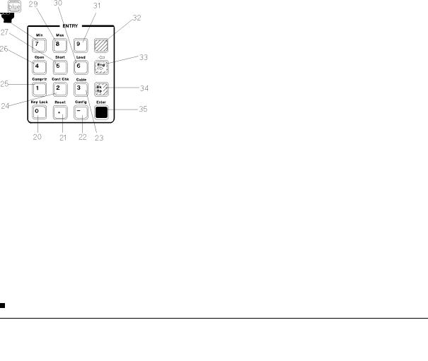
4263B
height
|
0 |
Key |
/ (Shift) Key Lock Key locks out any key input except for this key. |
|
|||
|
|||
|
. Key |
/ (Shift) Reset Key resets the 4263B to the default state. |
|
|
|||
|
|||
|
0 Key |
/ (Shift) Con guration Key sets the beeper setting and the power line frequency, |
|
|
|||
|
|||
|
and executes the internal test. |
||
|
3 |
Key / (Shift) Cable Key sets the cable length. |
|
|
|||
|
|||
|
2 |
Key |
/ (Shift) Contact Check Key toggles the contact check function between ON and OFF. |
|
|||
|
|||
|
1 |
Key |
/ (Shift) Comparator Key toggles the comparator function between ON and OFF. |
|
|||
|
|||
|
4 |
Key |
/ (Shift) Open Key executes an OPEN correction. |
|
|||
|
|||
|
5 |
Key |
/ (Shift) Short key executes a SHORT correction. |
|
|||
|
|||
|
6 |
Key |
/ (Shift) Load Key execute a LOAD correction. |
|
|||
|
|||
|
7 Key |
/ (Shift) Minimum key inputs the minimum value when setting a parameter. |
|
|
|||
|
|||
|
8 Key |
/ (Shift) Maximum Key inputs the maximum value when setting a parameter. |
|
|
|||
|
|||
|
9 |
Key |
|
|
|
||
|
|
||
Blue Shift Key activates the secondary functions printed above the front-panel keys.
Note |
In this manual, the blue Shift key is expressed as |
, even though the top of |
|
the key is not labeled with \blue". |
|
|
|
|
 Engineering Unit Key enters the engineering units: p, n, , m, k, and M.
 Back Space Key erases the last character entered when entering numeric values.
  Enter Key enters an input value to the 4263B and terminates the key entry for the current input function.
1-6 Getting Started
 Loading...