


 Loading...
5973 inert
Mass Selective Detector
Hardware Manual


 Agilent Technologies

5973 inert
Mass Selective Detector
Hardware Manual

Notices
© Agilent Technologies,
Inc. 2003
No part of this manual may be reproduced in any form or by any means (including electronic storage and retrieval or translation into a foreign language) without prior agreement and written consent from Agilent Technologies, Inc. as governed by United States and international copyright laws.
Manual Part Number
G2589-90071
Edition
Second edition, August 2003
Agilent Technologies, Inc.
2850 Centerville Road
Wilmington, DE 19808-1610
USA
Acknowledgements
Microsoft® and Windows® are U.S. registered trademarks of Microsoft Corporation.
Warranty
The material contained in this document is provided “as is,” and is subject to being changed, without notice, in future editions. Further, to the maximum extent permitted by applicable law, Agilent disclaims all warranties, either express or implied, with regard to this manual and any information contained herein, including but not limited to the implied warranties of merchantability and fitness for a particular purpose. Agilent shall not be liable for errors or for incidental or consequential damages in connection with the furnishing, use, or performance of this document or of any information contained herein. Should Agilent and the user have a separate written agreement with warranty terms covering the material in this document that conflict with these terms, the warranty terms in the separate agreement shall control.
Safety Notices
CAUTION
A CAUTION notice denotes a hazard. It calls attention to an operating procedure, practice, or the like that, if not correctly performed or adhered to, could result in damage to the product or loss of important data. Do not proceed beyond a CAUTION notice until the indicated conditions are fully understood and met.
WARNING
A WARNING notice denotes a hazard. It calls attention to an operating procedure, practice, or the like that, if not correctly performed or adhered to, could result in personal injury or death. Do not proceed beyond a WARNING notice until the indicated conditions are fully understood and met.

Table of Contents
Chapter |
Introduction |
|
5973 inert MSD Version, 14 |
|
About this manual, 15 |
|
Other User Information, 16 |
|
The 5973 inert MSD, 17 |
|
CI MSD hardware description, 19 |
|
Important Safety Warnings, 21 |
|
Safety and Regulatory Certifications, 24 |
|
Cleaning/Recycling the Product, 27 |
Chapter 1 |
Installing GC Columns |
|
To prepare a capillary column for installation, 32 |
|
To install a capillary column in a split/splitless inlet, 34 |
|
To condition a capillary column, 36 |
|
To install a capillary column in the GC/MSD interface, 38 |
|
To install a capillary column using the installation tool, 40 |
Chapter 2 |
Operating the MSD |
|
To view MSD analyzer temperature and vacuum status, 48 |
|
To set monitors for MSD temperature and vacuum status, 50 |
|
To set the MSD analyzer temperatures, 52 |
|
To set the GC/MSD interface temperature from the PC, 54 |
|
To monitor high vacuum pressure, 56 |
|
To measure column flow linear velocity, 58 |
|
To calculate column flow, 59 |
|
To tune the MSD, 60 |
|
To verify system performance, 61 |
|
Verify the tune performance, 61 |
|
Verify the sensitivity performance, 61 |
|
To remove the MSD covers, 62 |
|
Analyzer cover, 62 |
|
Lower MSD cover, 62 |
|
To vent the MSD, 64 |
|
To open the analyzer chamber, 66 |
|
To close the analyzer chamber, 68 |

|
To pump down the MSD, 70 |
|
To pump down the CI MSD, 72 |
|
To connect the gauge controller, 73 |
|
To move or store the MSD, 75 |
|
To set the interface temperature from a 6890 GC, 77 |
Chapter 3 |
Operating the CI MSD |
|
To switch from EI to CI operating mode, 82 |
|
To set up the software for CI operation, 83 |
|
To operate the reagent gas flow control module, 84 |
|
To set up methane reagent gas flow, 86 |
|
CI autotune, 88 |
|
To perform a positive CI autotune (methane only), 90 |
|
To perform a negative CI autotune (any reagent gas), 92 |
|
To verify positive CI performance, 94 |
|
To verify negative CI performance, 95 |
|
To monitor high vacuum pressure, 96 |
|
Typical pressure readings, 97 |
|
To use other reagent gases, 98 |
|
Isobutane CI, 99 |
|
Ammonia CI, 100 |
|
Carbon dioxide NCI, 101 |
|
To switch from CI to EI operating mode, 102 |
Chapter 4 |
Troubleshooting the MSD |
|
General symptoms, 106 |
|
GC does not turn on, 106 |
|
MSD does not turn on, 106 |
|
Foreline pump is not operating, 106 |
|
MSD turns on but then the foreline pump shuts off, 107 |
|
Control panel says “No server found”, 107 |
|
Chromatographic symptoms, 108 |
|
No peaks, 108 |
|
Peaks are tailing, 109 |
|
Peaks are fronting, 109 |
|
Peaks have flat tops, 110 |
|
Peaks have split tops, 110 |
|
Baseline is rising, 110 |
|
Baseline is high, 110 |
6

Baseline is falling, 110 Baseline wanders, 111
Retention times for all peaks drift – shorter, 111 Retention times for all peaks drift – longer, 111 Poor sensitivity, 112
Poor Repeatability, 112 Mass spectral symptoms, 113
No peaks, 113
Isotopes are missing or isotope ratios are incorrect, 113 High background, 113
High abundances at m/z 18, 28, 32, and 44 or at m/z 14 and 16, 114 Mass assignments are incorrect, 114
Peaks have precursors, 114
Peak widths are inconsistent, 114
Relative abundance of m/z 502 is less than 3%, 115
Spectra look different from those acquired with other MSDs, 115 High mass sensitivity is poor, 116
Pressure symptoms, 117
Foreline pressure is too high, 117
Analyzer chamber pressure is too high (EI operating mode), 117 Foreline pressure is too low, 118
Analyzer chamber pressure is too low, 118
Gauge controller displays 9.9+9 and then goes blank, 118 Power indicator on the gauge controller does not light, 119
Temperature symptoms, 120
Ion source will not heat up, 120
Mass filter (quad) heater will not heat up, 121 GC/MSD interface will not heat up, 121
Error messages, 122
Difficulty in mass filter electronics, 122 Difficulty with the electron multiplier supply, 122 Difficulty with the fan, 123
Difficulty with the HED supply, 123 Difficulty with the high vacuum pump, 123 High Foreline pressure, 124
Internal MS communication fault, 124 Lens supply fault, 124
Log amplifier ADC error, 124 No peaks found, 124
Temperature control disabled, 125 Temperature control fault, 125
The high vacuum pump is not ready, 126
7
|
The system is in standby, 126 |
|
The system is in vent state, 127 |
|
There is no emission current, 127 |
|
There is not enough signal to begin tune, 127 |
|
Air leaks, 128 |
|
Contamination, 129 |
Chapter 5 |
CI Troubleshooting |
|
Troubleshooting tips and tricks, 133 |
|
Air leaks, 134 |
|
How do I know if I have an air leak?, 134 |
|
How do I find the air leak?, 136 |
|
Pressure-related symptoms (overview), 138 |
|
Poor vacuum without reagent gas flow, 139 |
|
High pressure with reagent gas flow, 140 |
|
Pressure does not change when reagent flow is changed, 141 |
|
Signal-related symptoms (overview), 142 |
|
No peaks, 143 |
|
No reagent gas peaks in PCI, 143 |
|
No PFDTD peaks in PCI, 144 |
|
No reagent gas peaks in NCI, 144 |
|
No PFDTD calibrant peaks in NCI, 144 |
|
No sample peaks in NCI, 144 |
|
Large peak at m/z 238 in NCI OFN spectrum, 144 |
|
No or low reagent gas signal, 145 |
|
No or low PFDTD signal, but reagent ions are normal, 148 |
|
Excessive noise or low signal-to-noise ratio, 150 |
|
Large peak at m/z 19, 151 |
|
Peak at m/z 32, 152 |
|
Tuning-related symptoms (overview), 154 |
|
Reagent gas ion ratio is difficult to adjust or unstable, 155 |
|
High electron multiplier voltage, 157 |
|
Can not complete autotune, 158 |
|
Peak widths are unstable, 159 |
Chapter 6 |
Maintaining the MSD |
|
Before starting, 162 |
|
Maintaining the vacuum system 169 |
|
To check and add foreline pump oil, 170 |
|
|
|
8 |

To drain the foreline pump, 172 To refill the foreline pump, 174 To replace the turbo pump, 177
To separate the MSD from the GC, 178 To reconnect the MSD to the GC, 180 To remove the EI calibration vial, 182
To refill and reinstall the EI calibration vial, 184 To purge the calibration valves, 186
EI calibration valve, 186 CI calibration valve, 186
To remove the EI calibration valve, 187 To reinstall the EI calibration valve, 189
To replace the fan for the high vacuum pump, 191 To remove the triode gauge tube, 193
To reinstall a triode gauge tube, 195 To lubricate the side plate O-ring, 197 To lubricate the vent valve O-ring, 199
Maintaining the analyzer 201
To remove the ion source, 203
To disassemble the ion source, 205 To clean the ion source, 207
To reassemble the ion source, 212 To reinstall the ion source, 214 To remove a filament, 216
To reinstall a filament, 218
To remove the heater and sensor from the ion source, 220 To reinstall the heater and sensor in the ion source, 222 To remove the heater and sensor from the mass filter, 224 To reinstall the heater and sensor in the mass filter, 226 To replace the electron multiplier horn, 228
Maintaining the GC/MSD interface 230
To remove the GC/MSD interface heater and sensor, 232 To reinstall the GC/MSD interface heater and sensor, 234
Maintaining the electronics 236
To adjust the RF coils, 238
To replace the primary fuses, 240
9

Chapter 7 |
CI Maintenance |
|
To set up your MSD for CI operation, 245 |
|
To install the CI ion source, 246 |
|
To install the CI interface tip seal, 248 |
|
To clean the CI ion source, 250 |
|
Frequency of cleaning, 250 |
|
Cleaning procedure, 250 |
|
To minimize foreline pump damage from ammonia, 252 |
|
To replace the methane/isobutane gas purifier, 253 |
|
To clean the reagent gas supply lines (tubing), 254 |
|
To refill the CI calibrant vial, 255 |
Chapter 8 |
Vacuum System |
|
Turbo pump MSD vacuum system, 262 |
|
Turbo pump analyzer chamber, 263 |
|
Side plate, 264 |
|
Vacuum seals, 266 |
|
Face seals, 266 |
|
KF (NW) seals, 266 |
|
Compression seals, 266 |
|
High voltage feedthrough seal, 267 |
|
Foreline pump, 268 |
|
Turbomolecular pump and fan, 270 |
|
Standard turbo pump, 271 |
|
Performance turbo pump, 272 |
|
Calibration valves and vent valve, 273 |
|
Calibration valves, 273 |
|
EI calibration valve, 273 |
|
CI calibration valve, 273 |
|
Vent valve, 273 |
|
Triode gauge tube, 275 |
|
Gauge controller, 277 |
Chapter 9 |
GC/MSD Interfaces and |
|
CI Flow Control |
|
EI GC/MSD interface, 281 |
|
EI/CI GC/MSD interface (CI interface), 282 |
|
Reagent gas flow control module, 283 |
10
Chapter 10 |
Analyzer |
|
Ion source, 290 |
|
Ion source body, 290 |
|
Filaments, 292 |
|
Magnet, 293 |
|
Repeller, 293 |
|
Drawout plate and cylinder, 294 |
|
Ion focus, 294 |
|
Entrance lens, 294 |
|
Source Washer, 295 |
|
CI ion source, 297 |
|
Quadrupole mass filter, 299 |
|
AMU gain, 299 |
|
AMU offset, 300 |
|
219 width, 300 |
|
DC polarity, 301 |
|
Mass (axis) gain, 301 |
|
Mass (axis) offset, 301 |
|
Quadrupole maintenance, 302 |
|
Detector, 303 |
|
Detector focus lens, 303 |
|
High energy dynode, 303 |
|
Electron multiplier horn, 303 |
|
Analyzer heaters and radiators, 305 |
Chapter 11 |
Electronics |
|
Control panel and power switch, 310 |
|
Control panel, 310 |
|
Power switch, 310 |
|
Side board, 312 |
|
Electronics module, 313 |
|
Main board, 314 |
|
Signal amplifier board, 315 |
|
AC board, 316 |
|
LAN/MSD control card, 318 |
|
Power supplies, 319 |
|
Low voltage (ac-dc) power supply, 319 |
|
High voltage (HED) power supply, 319 |
|
Toroid transformer, 319 |
|
Back panel and connectors, 320 |
11

|
Interfacing to external devices, 322 |
|
Remote control processor, 322 |
|
Remote start signals, 322 |
Chapter 12 |
Parts |
|
Electronics, 327 |
|
Vacuum system, 332 |
|
Analyzer, 338 |
|
EI GC/MSD interface, 344 |
|
Consumables and maintenance supplies, 346 |
|
CI Parts, 350 |
Appendix A |
Chemical Ionization Theory |
|
Chemical ionization overview, 360 |
|
References on chemical ionization, 361 |
|
Positive CI theory, 362 |
|
Proton transfer, 364 |
|
Hydride abstraction, 366 |
|
Addition, 366 |
|
Charge exchange, 367 |
|
Negative CI theory, 368 |
|
Electron capture, 370 |
|
Dissociative electron capture, 371 |
|
Ion pair formation, 371 |
|
Ion-molecule reactions, 372 |
12

5973 inert MSD Version, 14 About this manual, 15 Other User Information, 16 The 5973 inert MSD, 17
CI MSD hardware description, 19 Important Safety Warnings, 21
Safety and Regulatory Certifications, 24 Cleaning/Recycling the Product, 27
Introduction
This manual describes the operation, troubleshooting, and maintenance of the Agilent Technologies 5973 inert Mass Selective Detector (MSD)

5973 inert MSD Version
5973 inert MSDs are equipped with or one of two turbomolecular (turbo) pumps. Chemical Ionization is available for the turbo pump MSDs only. The serial number label displays a product number that tells what kind of MSD you have. In this manual, the term “CI MSD” applies to the EI/PCI/NCI MSD.
Model number |
Description |
G2578A |
Standard turbo EI MSD |
G2579A |
Performance turbo EI MSD |
G2589A |
Performance turbo EI/PCI/NCI MSD |
14

Introduction
About this manual
About this manual
•The introduction describes general information about the 5973 inert MSD.
•Chapter 1 shows you how to prepare and install a capillary column.
•Chapter 2 describes basic tasks such as setting temperatures, monitoring pressures, tuning, and venting, and pumpdown.
•Chapter 3 describes basic tasks necessary to operate a CI MSD in CI mode.
•Chapter 4 provides a quick reference for identifying causes of poor instrument performance or malfunctions.
•Chapter 5 provides a quick reference for identifying problems unique to CI MSDs.
•Chapter 6 features maintenance procedures.
•Chapter 7 features maintenance procedures unique to CI MSDs.
•Chapter 8 describes operation of the components of the vacuum system.
•Chapter 9 describes the GC/MSD interface, and the CI flow module.
•Chapter 10 describes operation of the analyzer (ion source, mass filter, and detector).
•Chapter 11 describes the electronics that control the MSD.
•Chapter 12 contains illustrated parts identification and part numbers.
•Appendix A is an overview of chemical ionization theory.
For updated information, check the Agilent Technologies Life Sciences/ Chemical Analysis web site at http://www.agilent.com/chem.
15

Introduction
Other User Information
Other User Information
Additional information is contained in the following documentation:
•5973N and 5973 inert Mass Selective Detector Hardware Installation Manual1
•5973N and 5973 inert Mass Selective Detector Site Preparation Guide1
•6890 Series GC manuals
•GC accessories (autosampler, etc.) manuals
•G1701DA MSD Productivity ChemStations software manuals and online help
•5973N and 5973 inert Mass Selective Detector Specifications (59889991EN)
•Hydrogen Carrier Gas Safety Guide (5955-5398)1
•5973N and 5973 inert Mass Selective Detector Local Control Panel (LCP) Quick Reference1
•For updated information, see the Agilent Technologies web site at http://www.agilent.com/chem
1.Located on this CD-ROM [5973 and 5973 inert Mass Selective Detector User Information]
16

Introduction
The 5973 inert MSD
The 5973 inert MSD
The 5973 inert MSD is a stand-alone capillary GC detector
The 5973 inert Mass Selective Detector (MSD) is designed for use with the 6890 Series Gas Chromatograph. The MSD features:
•Control panel for locally monitoring and operating the MSD
•One of two different high vacuum pumps
•Rotary vane foreline pump
•Independently heated electron-ionization ion source
•Independently heated hyperbolic quadrupole mass filter
•High-energy dynode (HED) electron multiplier detector
•Independently heated GC/MSD interface
•Chemical ionization (EI/PCI/NCI) model available
Physical description
The 5973 inert MSD is a rectangular box, approximately 42 cm high, 26 cm wide, 65 cm deep. The weight is 26 kg for the standard turbo pump mainframe and 29 kg for the performance turbo pump mainframe. The attached rough pump weighs an additional
11 kg.
The basic components of the instrument are: the frame/cover assemblies, the control panel, the vacuum system, the GC interface, the electronics, and the analyzer.
The control panel allows local monitoring and operation of the MSD
The control panel acts as a local user interface to the MSD. You can perform some basic tasks such as running a tune, a method, or a sequence; and monitor MSD status from the control panel.
17

Introduction
The 5973 inert MSD
An optional gauge controller is available for measuring vacuum
The 5973 inert MSD is equipped with a triode ionization gauge tube. With an 59864B Gauge Controller, the tube can be used to measure pressure (high vacuum) in the vacuum manifold. Installation and operation of the gauge controller is described in this manual.
The gauge controller is required for chemical ionization (CI) operation.
|
5973 inert MSD models and features |
||
Feature |
G2578A |
G2579A |
G2589A |
High vac pump |
Standard turbo |
Performance turbo Performance turbo |
|
Optimal He column flow mL/min |
1 |
1 to 2 |
1 to 2 |
Maximum recommended gas flow, mL/mina |
2.0 |
4 |
4 |
Maximum gas flow, |
2.4 |
6.5 |
6.5 |
mL/minb |
|
|
|
Max column id |
0.32 mm (30m) |
0.53 mm (30 m) |
0.53 mm (30 m) |
CI capability |
no |
no |
PCI/NCI |
DIP capability |
yes |
yes |
no |
(3rd Party) |
|
|
|
a.Total gas flow into the MSD: column flow plus reagent gas flow (if applicable).
b.Expect degradation of spectral performance and sensitivity.
18

Introduction
CI MSD hardware description
CI MSD hardware description
In this manual, the term “CI MSD” applies to the EI/PCI/NCI MSD. The CI hardware allows the 5973 inert MSD to produce highquality, classical CI spectra, which include molecular adduct ions. A variety of reagent gases can be used.
The 5973 inert CI system adds to the 5973 inert MSD:
•Redesigned EI/CI GC/MSD interface
•CI ion source and interface tip seal
•Reagent gas flow control module
•Bipolar HED power supply (for PCI/NCI MSD only)
•A methane/isobutane gas purifier is provided, and is required. It removes oxygen, water, hydrocarbons, and sulfur compounds.
A high vacuum gauge controller (59864B) is required for the CI MSD.
To achieve the relatively high source pressure required for CI while still maintaining high vacuum in the quadrupole and detector, the MSD CI system has been carefully optimized. Special seals along the flow path of the reagent gas and very small openings in the ion source keep the source gases in the ionization volume long enough for the appropriate reactions to occur.
The EI/CI interface has special plumbing for reagent gas. A spring-loaded insulating seal fits onto the tip of the interface.
Switching back and forth between CI and EI takes less than an hour, although a 1– to 2–hour wait is required in order to purge the reagent gas lines and bake out water and other contaminants. Switching from PCI to NCI requires about 2 hours for the ion source to cool.
19

Introduction
CI MSD hardware description
6890 Series
ALS tower
6890 Series ALS tray
59864B High Vacuum Gauge
Controller
CI gas flow module (EI/PCI/NCI MSD only)
5973 inert
Mass Selective Detector
5973 inert MSD control panel
6890
Gas Chromatograph
5973 inert MSD serial number sticker
20
WA R N I N G
WA R N I N G
Introduction
Important Safety Warnings
Important Safety Warnings
Before moving on, there are several important safety notices that you should always keep in mind when using the 5973 inert Mass Selective Detector.
Many internal parts of the MSD carry dangerous voltages
If the MSD is connected to a power source, even if the power switch is off, potentially dangerous voltages exist on:
•The wiring between the MSD power cord and the AC power supply, the AC power supply itself, and the wiring from the AC power supply to the power switch.
With the power switch on, potentially dangerous voltages also exist on:
•All electronics boards in the instrument.
•The internal wires and cables connected to these boards.
•The wires for any heater (oven, detector, inlet, or valve box).
All these parts are shielded by covers. With the covers in place, it should be difficult to accidentally make contact with dangerous voltages. Unless specifically instructed to, never remove a cover unless the detector, inlet, or oven are turned off.
If the power cord insulation is frayed or worn, the cord must be replaced. Contact your Agilent service representative.
Electrostatic discharge is a threat to MSD electronics
The printed circuit (PC) boards in the MSD can be damaged by electrostatic discharge. Do not touch any of the boards unless it is absolutely necessary. If you must handle them, wear a grounded wrist strap and take other antistatic precautions. Wear a grounded wrist strap any time you must remove the MSD right side cover.
21

WA R N I N G
WA R N I N G
Introduction
Important Safety Warnings
Many parts are dangerously hot
Many parts of the MSD operate at temperatures high enough to cause serious burns. These parts include but are not limited to:
•The inlets
•The oven and its contents
•The detectors
•The column nuts attaching the column to an inlet or detector
•The valve box
You should always cool these areas of the MSD to room temperature before working on them. They will cool faster if you first set the temperature of the heated zone to room temperature. Turn the zone off after it has reached the setpoint. If you must perform maintenance on hot parts, use a wrench and wear gloves. Whenever possible, cool the part of the instrument that you will be maintaining before you begin working on it.
Be careful when working behind the instrument. During cool-down cycles, the MSD emits hot exhaust which can cause burns.
The insulation around the inlets, detectors, valve box, and the insulation cups is made of refractory ceramic fibers. To avoid inhaling fiber particles, we recommend the following safety procedures: ventilate your work area; wear long sleeves, gloves, safety glasses, and a disposable dust/mist respirator; dispose of insulation in a sealed plastic bag; wash your hands with mild soap and cold water after handling the insulation.
Hydrogen
Hydrogen gas may be used as carrier gas, and/or as fuel for the FID. When mixed with air, hydrogen can form explosive mixtures.
22

WA R N I N G
WA R N I N G
Introduction
Important Safety Warnings
When using hydrogen (H2) as the carrier gas or fuel gas, be aware that hydrogen gas can flow into the oven and create an explosion hazard. Therefore, be sure that the supply is off until all connections are made, and ensure that the inlet and detector column fittings are either connected to a column or capped at all times when hydrogen gas is supplied to the instrument.
Hydrogen is flammable. Leaks, when confined in an enclosed space, may create a fire or explosion hazard. In any application using hydrogen, leak test all connections, lines, and valves before operating the instrument. Always turn off the hydrogen supply at its source before working on the instrument.
The MSD cannot detect leaks in inlet and/or detector gas streams. For this reason, it is vital that column fittings should always be either connected to a column, or have a cap or plug installed.
When using hydrogen gas, check the system for leaks to prevent possible fire and explosion hazards based on local Environmental Health and Safety (EHS) requirements. Always check for leaks after changing a tank or servicing the gas lines. Always make sure the vent line is vented into a fume hood.
23

Introduction
Safety and Regulatory Certifications
Safety and Regulatory Certifications
The 5973 inert Mass Selective Detector conforms to the following safety standards:
•Canadian Standards Association (CSA): C22.2 No. 1010.1
•CSA/Nationally Recognized Test Laboratory (NRTL): UL 61010A–1
•International Electrotechnical Commission (IEC): 61010–1
•EuroNorm (EN): 61010–1
The 5973 inert Mass Selective Detector conforms to the following regulations on Electromagnetic Compatibility (EMC) and Radio Frequency Interference (RFI):
•CISPR 11/EN 55011: Group 1, Class A
•IEC/EN 61326
•AUS/NZ 
This ISM device complies with Canadian ICES-001. Cet appareil ISM est conforme a la norme NMB—001 du Canada.
The 5973 inert Mass Selective Detector is designed and manufactured under a quality system registered to ISO 9001.
Information
The Agilent Technologies 5973 inert Mass Selective Detector meets the following IEC (International Electro-technical Commission) classifications: Safety Class I, Transient Overvoltage Category II, Pollution Degree 2.
This unit has been designed and tested in accordance with recognized safety standards and is designed for use indoors. If the instrument is used in a manner not specified by the manufacturer, the protection provided by the instrument may be impaired. Whenever the safety protection of the 5973 Mass Selective Detector has been compromised, disconnect the unit from all power sources and secure the unit against unintended operation.
Refer servicing to qualified service personnel. Substituting parts or performing any unauthorized modification to the instrument may result in a safety hazard.
24
Introduction
Safety and Regulatory Certifications
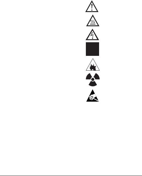
Symbols
Warnings in the manual or on the instrument must be observed during all phases of operation, service, and repair of this instrument. Failure to comply with these precautions violates safety standards of design and the intended use of the instrument. Agilent Technologies assumes no liability for the customer’s failure to comply with these requirements.
See accompanying instructions for more information.
Indicates a hot surface.
Indicates hazardous voltages.
Indicates earth (ground) terminal.
Indicates explosion hazard.
Indicates radioactivity hazard.
Indicates electrostatic discharge hazard.
Electromagnetic Compatibility
This device complies with the requirements of CISPR 11. Operation is subject to the following two conditions:
•This device may not cause harmful interference.
•This device must accept any interference received, including interference that may cause undesired operation.
If this equipment does cause harmful interference to radio or television reception, which can be determined by turning the equipment off and on, the user is encouraged to try one or more of the following measures:
25

Introduction
Safety and Regulatory Certifications
1Relocate the radio or antenna.
2Move the device away from the radio or television.
3Plug the device into a different electrical outlet, so that the device and the radio or television are on separate electrical circuits.
4Make sure that all peripheral devices are also certified.
5Make sure that appropriate cables are used to connect the device to peripheral equipment.
6Consult your equipment dealer, Agilent Technologies, or an experienced technician for assistance.
7Changes or modifications not expressly approved by Agilent Technologies could void the user’s authority to operate the equipment.
Sound Emission Certification for Federal Republic of Germany
Sound pressure
Sound pressure Lp < 70 dB am according to ISO 7779:1988.
Schalldruckpegel
Schalldruckpegel LP < 70 dB am nach EN 27779:1991.
26

Introduction
Cleaning/Recycling the Product
Cleaning/Recycling the Product
To clean the unit, disconnect the power and wipe down with a damp, lint-free cloth. For recycling, contact your local Agilent sales office.
27

Introduction
Cleaning/Recycling the Product
28

1
To prepare a capillary column for installation, 32
To install a capillary column in a split/splitless inlet, 34 To condition a capillary column, 36
To install a capillary column in the GC/MSD interface, 38 To install a capillary column using the installation tool, 40
Installing GC Columns
How to connect GC columns to the 5973 inert MSD

Installing GC columns
Before you can operate your GC/MSD system, you must select, condition, and install a GC column. This chapter will show you how to install and condition a column. For correct column and flow selection, you must know what type of vacuum system your MSD has. The serial number tag on the lower front of the left side panel shows the model number.
Many types of GC columns can be used with the MSD but there are some restrictions
During tuning or data acquisition the rate of column flow into the MSD should not exceed the maximum recommended flow. Therefore, there are limits to column length and flow. Exceeding recommended flow will result in degradation of mass spectral and sensitivity performance.
Remember that column flows vary greatly with oven temperature (unless the GC is set for constant flow). See To measure column flow linear velocity (page 58) for instructions on how to measure actual flow in your column. Use the Flow Calculation software to determine whether a given column will give acceptable flow with realistic head pressure.
Feature |
G2578A |
G2579A |
G2589A |
High vac pump |
Standard turbo |
Performance turbo |
Performance turbo, EI/ |
|
|
|
PCI/NCI |
Optimal gas flow, mL/mina |
1 |
1 to 2 |
1 to 2 |
Maximum recommended gas |
2.0 |
4 |
4 |
flow, mL/min |
|
|
|
Maximum gas flow, mL/minb |
2.4 |
6.5 |
4 |
Max column id |
0.32mm (30m) |
0.53 mm (30m) |
0.53mm (30m) |
a.Total gas flow into the MSD: column flow plus reagent gas flow (if applicable).
b.Expect degradation of spectral performance and sensitivity.
30
Loading...