


Agilent 4263B LCR Meter
Service Manual
SERIAL NUMBERS
This manual applies directly to instruments with serial number pre x JP1KD. For additional important information about serial numbers, read \Instruments Covered by This Manual" in Chapter 1 of this manual.
Agilent Part No. 04263-90033
Printed in JAPAN June 2000

Notice
The information contained in this document is subject to change without notice.
This document contains proprietary information that is protected by copyright. All rights are reserved. No part of this document may be photocopied, reproduced, or translated to another language without the prior written consent of the Agilent Technologies Company.
Agilent Technologies Japan, Ltd. Component Test PGU-Kobe
1-3-2, Murotani, Nishi-ku, Kobe-shi, Hyogo, 651-2241 Japan
c Copyright 1996, 2000 Agilent Technologies Japan, Ltd.

Manual Printing History
August 1996 : : : : : : : : : : : : : : : : : : : : : : : : : : : : : : : : : : : : : : : : : : First Edition (part number: 04263-90033) June 2000 : : : : : : : : : : : : : : : : : : : : : : : : : : : : : : : : : : : : : : : : : Second Edition (part number: 04263-90033)
iii

Safety Summary
The following general safety precautions must be observed during all phases of operation, service, and repair of this instrument. Failure to comply with these precautions or with speci c WARNINGS elsewhere in this manual may impair the protection provided by the equipment.
In addition it violates safety standards of design, manufacture, and intended use of the instrument.
The Agilent Technologies Company assumes no liability for the customer's failure to comply with these requirements.
Note |
4263B complies with INSTALLATION CATEGORY II and POLLUTION DEGREE 2 |
|
in IEC1010-1. 4263B is INDOOR USE product. |
Ground The Instrument
To avoid electric shock hazard, the instrument chassis and cabinet must be connected to a safety earth ground by the supplied power cable with earth blade.
DO NOT Operate In An Explosive Atmosphere
Do not operate the instrument in the presence of ammable gasses or fumes. Operation of any electrical instrument in such an environment constitutes a de nite safety hazard.
Keep Away From Live Circuits
Operating personnel must not remove instrument covers. Component replacement and internal adjustments must be made by quali ed maintenance personnel. Do not replace components with the power cable connected. Under certain conditions, dangerous voltages may exist even with the power cable removed. To avoid injuries, always disconnect power and discharge circuits before touching them.
DO NOT Service Or Adjust Alone
Do not attempt internal service or adjustment unless another person, capable of rendering rst aid and resuscitation, is present.
DO NOT Substitute Parts Or Modify Instrument
Because of the danger of introducing additional hazards, do not install substitute parts or perform unauthorized modi cations to the instrument. Return the instrument to a Agilent Technologies Sales and Service O ce for service and repair to ensure that safety features are maintained.
Dangerous Procedure W arnings
Warnings , such as the example below, precede potentially dangerous procedures throughout this manual. Instructions contained in the warnings must be followed.
Warning Dangerous voltages, capable of causing death, are present in this instrument. Use extreme caution when handling, testing, and adjusting this instrument.
iv

Certi cation
Agilent Technologies Company certi es that this product met its published speci cations at the time of shipment from the factory. Agilent Technologies further certi es that its
calibration measurements are traceable to the United States National Institute of Standards and Technology, to the extent allowed by the Institution's calibration facility, or to the calibration facilities of other International Standards Organization members.
Warranty
This Agilent Technologies instrument product is warranted against defects in material and workmanship for a period of one year from the date of shipment, except that in the case of certain components listed in General Information of this manual, the warranty shall be for the speci ed period. During the warranty period, Agilent Technologies Company will, at its option, either repair or replace products that prove to be defective.
For warranty service or repair, this product must be returned to a service facility designated by Agilent Technologies. Buyer shall prepay shipping charges to Agilent Technologies and Agilent Technologies shall pay shipping charges to return the product to Buyer. However, Buyer shall pay all shipping charges, duties, and taxes for products returned to Agilent Technologies from another country.
Agilent Technologies warrants that its software and rmware designated by Agilent Technologies for use with an instrument will execute its programming instruction when property installed on that instrument. Agilent Technologies does not warrant that the operation of the instrument, or software, or rmware will be uninterrupted or error free.
Limitation Of Warranty
The foregoing warranty shall not apply to defects resulting from improper or inadequate maintenance by Buyer, Buyer-supplied software or interfacing, unauthorized modi cation or misuse, operation outside the environmental speci cations for the product, or improper site preparation or maintenance.
No other warranty is expressed or implied. Agilent Technologies speci cally disclaims the implied warranties of merchantability and tness for a particular purpose.
v

Exclusive Remedies
The remedies provided herein are buyer's sole and exclusive remedies. Agilent Technologies shall not be liable for any direct, indirect, special, incidental, or consequential damages, whether based on contract, tort, or any other legal theory.
Assistance
Product maintenance agreements and other customer assistance agreements are available for Agilent Technologies products.
For any assistance, contact your nearest Agilent Technologies Sales and Service O ce. Addresses are provided at the back of this manual.
vi

Safety Symbols
General de nitions of safety symbols used on equipment or in manuals are listed below.
Instruction manual symbol: the product is marked with this symbol when it is necessary for the user to refer to the instruction manual.
Alternating current.
Direct current.
On (Supply).
O (Supply).
Frame or chassis terminal
This Warning sign denotes a hazard. It calls attention to a procedure, practice, condition or the like, which, if not correctly performed or adhered to, could result in injury or death to personnel.
This Caution sign denotes a hazard. It calls attention to a procedure, practice, condition or the like, which, if not correctly performed or adhered to, could result in damage to or destruction of part or all of the product.
Note denotes important information. It calls attention to a procedure, practice, condition or the like, which is essential to highlight.
vii

Documentation Map
Operation Manual
Operation Manual (Agilent Part Number: 04263-90010 for English edition, 04263-97010 for Japanese edition) explains speci cations, basic measurement explanations, and how to verify conformance to published speci cations.
Service Manual
Service Manual (Agilent Part Number: 04263-90033) explains how to adjust, troubleshoot, and repair the 4263B.
How To Use This Manual
This is the Service Manual for the 4263B LCR Meter. This manual contains adjustments and repair information, and consists of the following four chapters.
Chapter 1 General Information
Chapter 1 gives general information for servicing the 4263B. This chapter lists the recommended equipment for adjustments and troubleshooting.
Chapter 2 Adjustments
Chapter 2 describes the adjustments, required to ensure that the 4263B is within its published speci cations after it has been repaired, or it fails the performance tests.
Chapter 3 Assembly Replacement
Chapter 3 provides the information on replacing the 4263B assemblies. The information includes replaceable assembly lists, and removal and installation procedures.
Chapter 4 Troubleshooting
Chapter 4 provides the information on troubleshooting the 4263B. The information includes theory of operation and information on faulty assembly isolation.
Appendix A Manual Changes
Appendix A contains manual changes and provides information for using this manual with 4263Bs manufactured before the printing date of the manual.
Appendix B Default Jumper and Switch Settings
Appendix B describes the settings of the jumpers and switches on the 4263B A2 CPU Board Assembly. The information is required when the A2 assembly is replaced.
viii

Contents
1. General Information |
|
Introduction . . . . . . . . . . . . . . . . . . . . . . . . . . . . . . . . . |
1-1 |
Instruments Covered by This Manual . . . . . . . . . . . . . . . . . . . . . |
1-1 |
Required Equipment . . . . . . . . . . . . . . . . . . . . . . . . . . . . . |
1-2 |
2. Adjustments |
|
Introduction . . . . . . . . . . . . . . . . . . . . . . . . . . . . . . . . . |
2-1 |
Safety Consideration . . . . . . . . . . . . . . . . . . . . . . . . . . . . |
2-1 |
Required Equipment . . . . . . . . . . . . . . . . . . . . . . . . . . . . . |
2-1 |
Adjustment Tools . . . . . . . . . . . . . . . . . . . . . . . . . . . . . . |
2-2 |
Adjustable Components . . . . . . . . . . . . . . . . . . . . . . . . . . . |
2-2 |
Factory-Selected Components . . . . . . . . . . . . . . . . . . . . . . . . . |
2-2 |
EEPROM Write Protect Switch . . . . . . . . . . . . . . . . . . . . . . . . |
2-2 |
Related Adjustments . . . . . . . . . . . . . . . . . . . . . . . . . . . . . |
2-2 |
Adjustment Program . . . . . . . . . . . . . . . . . . . . . . . . . . . . . |
2-3 |
Program Installation . . . . . . . . . . . . . . . . . . . . . . . . . . . . |
2-5 |
Making a Working Copy . . . . . . . . . . . . . . . . . . . . . . . . . |
2-5 |
De ning the Con guration . . . . . . . . . . . . . . . . . . . . . . . . |
2-5 |
Program Execution . . . . . . . . . . . . . . . . . . . . . . . . . . . . |
2-5 |
Adjustments Procedure References . . . . . . . . . . . . . . . . . . . . . . |
2-7 |
Signal Source Level Adjustment . . . . . . . . . . . . . . . . . . . . . . . |
2-7 |
Equipment . . . . . . . . . . . . . . . . . . . . . . . . . . . . . . . |
2-7 |
Setup . . . . . . . . . . . . . . . . . . . . . . . . . . . . . . . . . . |
2-7 |
Impedance Measurement 0m Adjustment . . . . . . . . . . . . . . . . . . |
2-8 |
Equipment . . . . . . . . . . . . . . . . . . . . . . . . . . . . . . . |
2-8 |
Setup . . . . . . . . . . . . . . . . . . . . . . . . . . . . . . . . . . |
2-8 |
Impedance Measurement 1m Adjustment . . . . . . . . . . . . . . . . . . |
2-9 |
Equipment . . . . . . . . . . . . . . . . . . . . . . . . . . . . . . . |
2-9 |
Setup . . . . . . . . . . . . . . . . . . . . . . . . . . . . . . . . . . |
2-9 |
Impedance Measurement 2m Adjustment . . . . . . . . . . . . . . . . . . |
2-10 |
Impedance Measurement 4m Adjustment . . . . . . . . . . . . . . . . . . |
2-10 |
3. Assembly Replacement
Introduction . . . . . . . . . . . . . . . . . . . . . . . . . . . . . . . . . |
3-1 |
Ordering Information . . . . . . . . . . . . . . . . . . . . . . . . . . . . |
3-1 |
Restored Exchange Assemblies . . . . . . . . . . . . . . . . . . . . . . . . |
3-1 |
Replacing the A2 CPU Board Assembly . . . . . . . . . . . . . . . . . . . . |
3-2 |
Replaceable Assembly List . . . . . . . . . . . . . . . . . . . . . . . . . . |
3-2 |
Replaceable Mechanical Parts List . . . . . . . . . . . . . . . . . . . . . . . |
3-5 |
Disassembly Procedures . . . . . . . . . . . . . . . . . . . . . . . . . . . |
3-9 |
Tools and Fasteners . . . . . . . . . . . . . . . . . . . . . . . . . . . . |
3-9 |
Cover Removal . . . . . . . . . . . . . . . . . . . . . . . . . . . . . . |
3-9 |
A1 Main Board Removal . . . . . . . . . . . . . . . . . . . . . . . . . . |
3-10 |
Removal Procedure . . . . . . . . . . . . . . . . . . . . . . . . . . . |
3-10 |
A2 CPU Board Assembly Removal . . . . . . . . . . . . . . . . . . . . . |
3-10 |
Removal Procedure . . . . . . . . . . . . . . . . . . . . . . . . . . . |
3-10 |
Contents-1
|
A5 AC Inlet Board Assembly Removal . . . . . . . . . . . . . . . . . . . . |
3-10 |
|
Removal Procedure . . . . . . . . . . . . . . . . . . . . . . . . . . . |
3-10 |
|
Keyboard Assembly Removal . . . . . . . . . . . . . . . . . . . . . . . . |
3-11 |
|
Removal Procedure . . . . . . . . . . . . . . . . . . . . . . . . . . . |
3-11 |
|
LCD Assembly Removal . . . . . . . . . . . . . . . . . . . . . . . . . . |
3-11 |
|
Removal Procedure . . . . . . . . . . . . . . . . . . . . . . . . . . . |
3-11 |
|
BNC Connector Removal . . . . . . . . . . . . . . . . . . . . . . . . . . |
3-11 |
|
Removal Procedure . . . . . . . . . . . . . . . . . . . . . . . . . . . |
3-11 |
4. |
Troubleshooting |
|
|
Introduction . . . . . . . . . . . . . . . . . . . . . . . . . . . . . . . . . |
4-1 |
|
Safety Considerations . . . . . . . . . . . . . . . . . . . . . . . . . . . |
4-1 |
|
Required Equipment . . . . . . . . . . . . . . . . . . . . . . . . . . . . . |
4-1 |
|
After Service Product Safety Checks . . . . . . . . . . . . . . . . . . . . . |
4-2 |
|
Theory of Operation . . . . . . . . . . . . . . . . . . . . . . . . . . . . . |
4-3 |
|
Overall Measurement Theory . . . . . . . . . . . . . . . . . . . . . . . . |
4-3 |
|
Overall Block Diagram . . . . . . . . . . . . . . . . . . . . . . . . . . . |
4-4 |
|
Analog Section . . . . . . . . . . . . . . . . . . . . . . . . . . . . . . |
4-5 |
|
Signal Source Section . . . . . . . . . . . . . . . . . . . . . . . . . . |
4-6 |
|
Transducer Section . . . . . . . . . . . . . . . . . . . . . . . . . . . |
4-7 |
|
Vector Ratio Detector Section . . . . . . . . . . . . . . . . . . . . . . . |
4-8 |
|
Transformer Parameter Measurement (Option 001 only) . . . . . . . . . . |
4-8 |
|
Digital Section . . . . . . . . . . . . . . . . . . . . . . . . . . . . . . . |
4-9 |
|
Power Supply Section . . . . . . . . . . . . . . . . . . . . . . . . . . . |
4-10 |
|
Troubleshooting . . . . . . . . . . . . . . . . . . . . . . . . . . . . . . . |
4-11 |
|
Check Procedure References . . . . . . . . . . . . . . . . . . . . . . . . |
4-13 |
|
Check 1, DC-DC Converter Output Voltage . . . . . . . . . . . . . . . . |
4-13 |
|
Check 2, LCD Displays Anything? . . . . . . . . . . . . . . . . . . . . . |
4-14 |
|
Check 3, LCD Operates Correctly? . . . . . . . . . . . . . . . . . . . . |
4-14 |
|
Check 4, Any Error Message on LCD? . . . . . . . . . . . . . . . . . . . |
4-14 |
|
Check 5, CPU Related Error Message? . . . . . . . . . . . . . . . . . . . |
4-14 |
|
Check 6, CPU Power LED Lights? . . . . . . . . . . . . . . . . . . . . . |
4-14 |
|
Check 7, Any Error Code on LED? . . . . . . . . . . . . . . . . . . . . |
4-15 |
|
Check 8, CPU Fuse High Lead Voltage . . . . . . . . . . . . . . . . . . . |
4-16 |
|
Check 9, Fuse and Line Switch . . . . . . . . . . . . . . . . . . . . . . |
4-16 |
|
Check 10, DC-DC Converter Input Voltage . . . . . . . . . . . . . . . . . |
4-17 |
|
Check 11, DC-DC Converter Open Output Voltages . . . . . . . . . . . . . |
4-18 |
|
Check 12, Transformer Secondary Voltage . . . . . . . . . . . . . . . . . |
4-19 |
A. |
Manual Changes |
|
|
Introduction . . . . . . . . . . . . . . . . . . . . . . . . . . . . . . . . . |
A-1 |
|
Manual Changes . . . . . . . . . . . . . . . . . . . . . . . . . . . . . . . |
A-1 |
B. Default Jumper and Switch Settings |
|
|
|
Introduction . . . . . . . . . . . . . . . . . . . . . . . . . . . . . . . . . |
B-1 |
|
Jumper and Switch Settings . . . . . . . . . . . . . . . . . . . . . . . . . |
B-1 |
Index
Contents-2
Figures
1-1. |
Serial Number Label . . . . . . . . . . . . . . . . . . . . . . . . . . . . |
1-1 |
2-1. |
Adjustment Program Flow . . . . . . . . . . . . . . . . . . . . . . . . . |
2-3 |
2-2. |
Signal Source Level Adjustment Setup . . . . . . . . . . . . . . . . . . . |
2-7 |
2-3. |
Impedance Measurement 0m Adjustment Setup . . . . . . . . . . . . . . . |
2-8 |
2-4. |
Impedance Measurement 1m Adjustment Setup . . . . . . . . . . . . . . . |
2-9 |
3-1. |
Cover Removal . . . . . . . . . . . . . . . . . . . . . . . . . . . . . . |
3-9 |
4-1. |
Voltage Current Ratio Measurement Principle . . . . . . . . . . . . . . . . |
4-3 |
4-2. |
4263B Overall Block Diagram . . . . . . . . . . . . . . . . . . . . . . . . |
4-4 |
4-3. |
Analog Section Block Diagram . . . . . . . . . . . . . . . . . . . . . . . |
4-5 |
4-4. |
Signal Source Section Block Diagram . . . . . . . . . . . . . . . . . . . . |
4-6 |
4-5. |
Transducer Block Diagram . . . . . . . . . . . . . . . . . . . . . . . . . |
4-7 |
4-6. |
Vector Ratio Detector Block Diagram . . . . . . . . . . . . . . . . . . . . |
4-8 |
4-7. |
Basic Transformer Measurement Setup . . . . . . . . . . . . . . . . . . . |
4-8 |
4-8. |
Digital Section Block Diagram . . . . . . . . . . . . . . . . . . . . . . . |
4-9 |
4-9. |
Power Supply Section Block Diagram . . . . . . . . . . . . . . . . . . . . |
4-10 |
4-10. Troubleshooting Flow Chart . . . . . . . . . . . . . . . . . . . . . . . . |
4-12 |
|
4-11. DC-DC Converter Output Voltage Check . . . . . . . . . . . . . . . . . . . |
4-13 |
|
4-12. CPU Board Assembly LED Light Sequence . . . . . . . . . . . . . . . . . . |
4-15 |
|
4-13. Location of High Lead of A2F1 Fuse . . . . . . . . . . . . . . . . . . . . |
4-16 |
|
4-14. DC-DC Converter Input Voltage Check . . . . . . . . . . . . . . . . . . . |
4-17 |
|
4-15. DC-DC Converter Output Connector . . . . . . . . . . . . . . . . . . . . |
4-18 |
|
4-16. Transformer Secondary Voltage Check . . . . . . . . . . . . . . . . . . . |
4-19 |
|
B-1. |
Jumper and Switch Settings . . . . . . . . . . . . . . . . . . . . . . . . |
B-1 |
Tables
1-1. Required Equipment . . . . . . . . . . . . . . . . . . . . . . . . . . . . |
1-2 |
1-2. Required Language Extensions . . . . . . . . . . . . . . . . . . . . . . . |
1-2 |
2-1. Related Adjustments . . . . . . . . . . . . . . . . . . . . . . . . . . . . |
2-2 |
3-1. Replaceable Major Assembly List . . . . . . . . . . . . . . . . . . . . . . |
3-3 |
3-2. A2 CPU Board Assembly, Replaceable Assembly List . . . . . . . . . . . . . |
3-4 |
3-3. Replaceable Assembly List . . . . . . . . . . . . . . . . . . . . . . . . . |
3-4 |
3-4. Replaceable Mechanical Parts List 1 . . . . . . . . . . . . . . . . . . . . . |
3-5 |
3-5. Replaceable Mechanical Parts List 2 . . . . . . . . . . . . . . . . . . . . . |
3-6 |
3-6. Replaceable Mechanical Parts List 3 . . . . . . . . . . . . . . . . . . . . . |
3-7 |
3-7. Replaceable Mechanical Parts List 4 . . . . . . . . . . . . . . . . . . . . . |
3-8 |
4-1. DC-DC Converter Output Voltage (Connected) . . . . . . . . . . . . . . . . |
4-13 |
4-2. DC-DC Converter Open Output Voltages . . . . . . . . . . . . . . . . . . . |
4-18 |
A-1. Manual Changes by Serial Number . . . . . . . . . . . . . . . . . . . . . |
A-1 |
Contents-3
1
General Information
Introduction
This chapter provides information on instruments covered by this manual and required equipment for the adjustments and troubleshooting.
Instruments Covered by This Manual
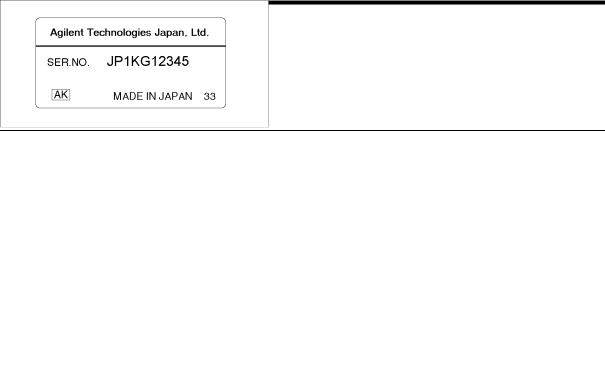
Agilent Technologies uses a two-section, nine character serial number which is printed on the serial number label (Figure 1-1) attached to the instrument's rear panel. The rst ve characters are the serial pre x, and the last ve digits are the su x.
Figure 1-1. Serial Number Label
An instrument manufactured after the printing date of this manual may have a serial number pre x that is not listed on the title page. This unlisted serial number pre x indicates the instrument is di erent from those described in this manual. The manual for this new instrument may be accompanied by a yellow Manual Changes supplement or have a di erent
manual part number. This sheet contains \change information" that explains how to adapt the manual to the newer instrument.
In addition to change information, the supplement may contain information for correcting errors (Errata) in the manual. To keep this manual as current and accurate as possible, Agilent Technologies recommends that you periodically request the latest Manual Changes supplement. The supplement for this manual is identi ed by this manual's printing date and its part number, both of which appear on the manual's title page. Complimentary copies of the supplement are available from Agilent Technologies. If the serial pre x or number of an instrument is lower than that on the title page of this manual, see Appendix A, Manual Changes . For information concerning, a serial number pre x that is not listed on the title page or in the Manual Change supplement, contact the nearest Agilent Technologies o ce.
General Information 1-1

Required Equipment
Table 1-1 lists the required equipment for adjusting and troubleshooting the 4263B. Table 1-2 lists the required language extensions to be used with the adjustment program.
Table 1-1. Required Equipment
Equipment |
Requirements |
Recommended Model |
Qty. |
Use |
|
|
|
|
|
Multimeter |
AC V Accuracy: < 2.5% |
3458A or 3478A |
1 |
A1 , T2 |
|
(at 100 kHz) |
|
|
|
Standard Resistors |
No Substitute |
42030A |
|
A |
1 |
||||
Open Termination |
No Substitute |
42090A3 |
1 |
A |
Short Termination |
No Substitute |
42091A3 |
1 |
A |
Computer |
No Substitute |
HP 9000 series 200 or 3004 |
1 |
A |
|
|
RAM 4M bytes |
|
|
Operating System |
BASIC 5.1 or higher |
HP 98616A |
1 |
A |
Adjustment Program |
No substitute |
Agilent PN 04263-65005 |
|
A |
1 |
||||
Cable |
BNC(m)-BNC(m) Cable |
Agilent PN 8120-1839 |
1 |
A |
|
Dual Banana-BNC(m) Cable |
Agilent PN 11001-60001 |
|
A |
|
1 |
|||
|
Test Leads (1 m) |
16048A |
1 |
A |
|
Test Leads (2 m) |
16048D |
1 |
A |
|
Test Leads (4 m) |
16048E |
|
A |
|
1 |
|||
Adapter |
BNC(f)-BNC(f) Adapter |
Agilent PN 1250-0080 |
4 |
A |
|
|
|
|
|
1 |
Adjustment |
2 |
Troubleshooting |
3 This model is also included in the 42100A, Four Terminal Pair Resistor Set 4 Excluding the HP 9826A
Table 1-2. Required Language Extensions
Name |
Ver. |
|
Name |
Ver. |
CLOCK |
5.0 |
|
CS80 |
5.01 |
COMPLEX |
5.1 |
|
EDIT |
5.1 |
CRTA |
5.1 |
|
ERR |
5.1 |
CRTX |
5.1 |
|
FGPIB |
5.0 |
Name |
Ver. |
|
Name |
Ver. |
GRAPH |
5.2 |
|
KBD |
5.1 |
GRAPHX |
5.2 |
|
MAT |
5.1 |
GPIB |
5.0 |
|
MS |
5.1 |
IO |
5.1 |
|
PDEV |
5.0 |
1 This language extension depends on the mass storage type used.
1-2 General Information

2
Adjustments
Introduction
This chapter describes the adjustments required to ensure the 4263B is within its published speci cations after it has been repaired, or when it fails the performance tests. The adjustments should be performed along with periodic maintenance to keep the 4263B in optimum operating condition. If proper performance cannot be achieved after adjustments, proceed to Chapter 4.
Note |
To ensure proper results and correct instrument operation, a 30 minute |
|
warm-up and stabilization is required before performing the adjustments. |
Safety Consideration
This chapter contains NOTEs, CAUTIONs, and WARNINGs which must be followed to ensure operator safety and to maintain the instrument in a safe and serviceable condition. The adjustments covered in this chapter should be performed only by a quali ed person who is aware of the hazards.
Warning Any interruption of the protective ground conductor (inside or outside the instrument) or disconnection of the protective ground terminal can make the instrument dangerous. Intentional interruption of the protective ground system for any reason is prohibited.
Required Equipment
Table 1-1 lists the equipment required to perform the adjustments. Use only calibrated test equipment when adjusting the 4263B.
Adjustments 2-1

Adjustment Tools
No hand tools are required for the adjustments.
Adjustable Components
There are no adjustable components, such as variable capacitors or variable resistors, in the 4263B. All adjustments are performed by updating the adjustment data stored in the internal EEPROM.
Factory-Selected Components
No factory-selected components are used in the 4263B
EEPROM Write Protect Switch
There are no EEPROM write protect switches in the 4263B.
Related Adjustments
There are two adjustments for the 4263B. Table 2-1 lists the adjustments that must be performed if an assembly has been replaced.
Table 2-1. Related Adjustments
|
Assembly Replaced |
Required Adjustment |
|
|
|
|
|
A1 |
Main Board Assy |
All adjustments |
|
A2 |
CPU Board Assy without ROM |
None1 |
|
A5 |
AC Inlet Board Assy |
None |
|
LCD Assembly |
None |
||
DC-DC Converter Unit |
None |
||
Keyboard Assembly |
None |
||
|
|
|
|
1 If the EEPROM, A2U1, is replaced, all adjustments are required.
2-2 Adjustments

Adjustment Program
The adjustment program listed in Table 1-1 is required for the adjustments. Using the program, the computer controls the 4263B and the other pieces of equipment to obtain the adjustment data, and stores the data in the 4263B internal EEPROM, A2U1.
The adjustment program runs on the computer listed in Table 1-1. The program should be installed into your computer according to the procedure described in \Program Installation". To start the program after it has been installed, refer to the \Program Execution".
Figure 2-1 shows the adjustment program ow. The following lists the brief explanation for each menu item. At the end of each adjustment, the program writes the obtained adjustment data both to the 4263B internal EEPROM and to the unit-serial-number dependent le on the disk.
|
Figure 2-1. Adjustment Program Flow |
INITIAL SETUP |
de nes the standards' calibration values. Update the standard's |
|
calibration values if necessary. |
Signal Source Level |
obtains the data to adjust the actual signal source output voltage to the |
Adjustment |
set value. This adjustment should be performed if any performance test |
|
fails. |
Impedance |
obtains the data to adjust the actual measurement impedance to the |
Measurement 0m |
standards' value, when no test leads are used. This adjustment should be |
Adjustment |
performed if the performance test, Impedance Measurement Accuracy |
|
Test, fails. Perform the Signal Source Level Adjustment prior to this |
|
adjustment. |
|
Adjustments 2-3 |

Impedance |
|
obtains the data to adjust the actual measurement impedance to the |
Measurement 1m |
standards' value, when the 1m test leads are used. This adjustment |
|
Adjustment |
|
should be performed if the performance test, Impedance Measurement |
|
|
Accuracy Test, fails. Perform the Impedance Measurement 0m |
|
|
Adjustment prior to this adjustment. |
Impedance |
|
obtains the data to adjust the actual measurement impedance to the |
Measurement 2m |
standards' value, when the 2m test leads are used. This adjustment |
|
Adjustment |
|
should be performed if the performance test, Impedance Measurement |
|
|
Accuracy Test, fails. Perform the Impedance Measurement 0m |
|
|
Adjustment prior to this adjustment. |
Impedance |
|
obtains the data to adjust the actual measurement impedance to the |
Measurement 4m |
standards' value, when the 4m test leads are used. This adjustment |
|
Adjustment |
|
should be performed if the performance test, Impedance Measurement |
|
|
Accuracy Test, fails. Perform the Impedance Measurement 0m |
|
|
Adjustment prior to this adjustment. |
Rewrite EEPROM |
writes the adjustment data, which is stored in the unit-serial-number |
|
|
|
dependent le, to the EEPROM. Only the adjustment data of previously |
|
|
adjusted item(s) will be written. |
|
|
|
Note |
Make sure that the correct line frequency (50 or 60Hz) has been selected in the |
|
|
\UUT: 4263B" window preceding the Main Menu. This selection will improve |
|
|
the adjustment data accuracy. |
|
|
|
|
|
|
|
Note |
Because the Impedance Measurement 0m Adjustment serves the reference |
|
|
data for the other Impedance Measurement Adjustments, it must have been |
|
|
performed prior to the 1m, 2m, and 4m adjustments. |
|
|
|
|
|
|
|
Note |
Although performing some of the Impedance Measurement Adjustments may |
|
|
satisfy the user's requirement (e.g. for users using the 4m test leads only for |
|
|
the application), it is strongly recommended to perform all the Impedance |
|
Measurement Adjustments. If only one of the 1m, 2m, and 4m adjustments is performed after the 0m adjustment, the data for the remaining Impedance
Measurement Adjustments are invalid. For example, if only the 4m adjustment is performed after the 0m adjustment, the measurement accuracy for the 1m and 2m may be out of the speci cation.
2-4 Adjustments

Program Installation
The adjustment program must be installed in the computer using the following procedures. The installation can be divided into two stages, \Making a Working Copy" and \De ning the Con guration".
Making a Working Copy
Copy the contents of the adjustment program disk to a working disk or to the harddisk to prevent the program les from accidental deletion or destruction. Use the working disk or the harddisk and store the original disk in a safe place.
De ning the Con guration
De ne the con guration of the adjustment equipment. The con guration includes the type and the GPIB address of the multimeter to be used. Because the program depends on equipment con guration, it must be rede ned if the equipment con guration has changed.
Refer to the following procedure to de ne the con guration.
1.Turn on the computer and bring up the BASIC system.
2.Set the Mass Storage Unit Speci er to the drive/directory where the adjustment program exists using the MSI command.
3.Load the \TE_A4263B " le from the adjustment program disk by pressing
LOAD "TE_A4263B" 4Return5 (or 4Enter5).
4.Run the loaded program by pressing RUN.
5.As the program instructs, select the type of the multimeter to be used and enter its GPIB address.
Note |
Once the multimeter type and GPIB addresses are set, they cannot be changed |
|
unless the con guration is rede ned. |
Program Execution
Perform the following steps to start the adjustment program.
Note |
Install the program prior to execution. Refer to \Program Installation". |
1.Turn on the computer and bring up the BASIC system. Refer to the Table 1-2 for the required language extensions.
2.Set the Mass Storage Unit Speci er to the drive/directory where the adjustment program exists using the MSI command.
3.Load the program, \ADJ4263B " by pressing LOAD "ADJ4263B" 4Return5 (or 4Enter5).
4.Execute the program by pressing RUN .
Adjustments 2-5
 Loading...