


 Loading...
Agilent 6890
Gas Chromatograph
Maintaining Your GC


 Agilent Technologies

Notices
© Agilent Technologies, Inc. 2007
No part of this manual may be reproduced in any form or by any means (including electronic storage and retrieval or translation into a foreign language) without prior agreement and written consent from Agilent Technologies, Inc. as governed by United States and international copyright laws.
Manual Part Number
G1530-90010
Edition
First edition, March 2007
Printed in USA
Agilent Technologies, Inc.
2850 Centerville Road
Wilmington, DE 19808-1610 USA
Warranty
The material contained in this document is provided “as is,” and is subject to being changed, without notice, in future editions. Further, to the maximum extent permitted by applicable law, Agilent disclaims all warranties, either express or implied, with regard to this manual and any information contained herein, including but not limited to the implied warranties of merchantability and fitness for a particular purpose. Agilent shall not be liable for errors or for incidental or consequential damages in connection with the furnishing, use, or performance of this document or of any information contained herein. Should Agilent and the user have a separate written agreement with warranty terms covering the material in this document that conflict with these terms, the warranty terms in the separate agreement shall control.
Safety Notices
CAUTION
A CAUTION notice denotes a hazard. It calls attention to an operating procedure, practice, or the like that, if not correctly performed or adhered to, could result in damage to the product or loss of important data. Do not proceed beyond a CAUTION notice until the indicated conditions are fully understood and met.
WARNING
A WARNING notice denotes a hazard. It calls attention to an operating procedure, practice, or the like that, if not correctly performed or adhered to, could result in personal injury or death. Do not proceed beyond a WARNING notice until the indicated conditions are fully understood and met.
Contents
1 About Maintaining the GC
Overview of Maintenance 10
Tools and Materials Required for Maintenance 12
Safety Information 14
Preparing the GC for Maintenance 15
2 Maintaining Capillary Columns
Consumables and Parts for Columns |
18 |
|
|
To Install a Capillary Column Hanger |
19 |
|
|
To Condition a Capillary Column |
20 |
|
|
To Cut a Loop from a Column |
23 |
|
|
To Reverse a Column and Bakeout Contaminants 24 |
|
||
To Attach a Capillary Column Using SilTite Metal Fittings |
26 |
||
To Disconnect Fused Silica Tubing From a SilTite Fitting |
29 |
||
3 Maintaining the Split/Splitless Inlet
Consumables and Parts for the Split/Splitless Inlet |
32 |
|
Exploded Parts View of the Split/Splitless Inlet 35 |
|
|
To Install a Capillary Column with the Split/Splitless Inlet |
36 |
|
To Change the Septum on the Split/Splitless Inlet |
40 |
|
To Clean the Septum Seat in the Insert Assembly of the Split/Splitless |
||
Inlet 42 |
|
|
To Change the Liner and O-Ring on the Split/Splitless Inlet |
44 |
|
To Replace the Gold Seal on the Split/Splitless Inlet |
46 |
|
To Replace the Filter in the Split Vent Line 48
To Clean the Split/Splitless Inlet 49
To Bakeout Contaminants from the Split/Splitless Inlet 51
4 Maintaining the Purged Packed Inlet
Consumables and Parts for the Purged Packed Inlet 54
Exploded Parts View of the Purged Packed Inlet 57
To Install a Capillary Column with the Purged Packed Inlet 58
To Change the Septum on the Purged Packed Inlet 62
Maintaining Your GC |
3 |
To Clean the Septum Seat in the Purged Packed Inlet 64
To Install an Adapter on the Purged Packed Inlet |
66 |
|
|
To Change the O-Ring on the Purged Packed Inlet |
68 |
|
|
To Change the Glass Liner on the Purged Packed Inlet |
69 |
||
To Install an Insulation Cup on the Purged Packed Inlet |
71 |
||
To Clean the Purged Packed Inlet |
72 |
|
|
To Bakeout Contaminants from the Purged Packed Inlet |
74 |
||
To Install a Packed Metal Column |
75 |
|
|
To Install a Packed Column Adapter on a Detector Fitting |
77 |
||
To Install a Packed Glass Column |
79 |
|
|
To Condition a Packed Column |
82 |
|
|
To Install Ferrules on a Packed Metal Column 84
5 Maintaining the COC Inlet
Consumables and Parts for the COC Inlet 86
Exploded Parts View of the COC Inlet |
89 |
To Install a Capillary Column with the COC Inlet 90 |
|
To Check the Needle-to-Column Size on the COC Inlet 93 |
|
To Change a Septum on the COC Inlet |
94 |
To Install an Insert on the COC Inlet |
96 |
To Clean the COC Inlet 98 |
|
To Replace the Needle Support Assembly in a 7683B Injector 100
To Replace a Needle in a Syringe 103
To Replace the Fused Silica Needle in a Syringe for the COC Inlet 104 To Bakeout Contaminants from the COC Inlet 106
6 Maintaining the PTV Inlet
Consumables and Parts for the PTV Inlet 108 |
|
Exploded Parts View of the PTV Inlet 110 |
|
To Install a Capillary Column with the PTV Inlet |
111 |
To Clean the Septumless Head on the PTV Inlet |
114 |
To Replace the Septumless Head Teflon Ferrule on the PTV Inlet 117 To Change the Septum on the PTV Inlet 119
4 |
Maintaining Your GC |
To Clean the Septum Seat in the Septum Head Assembly of the PTV
|
Inlet 121 |
|
|
|
|
|
|
|
To Change the Liner on the PTV Inlet |
123 |
|
|
|||
|
To Replace the Inlet Adapter for the PTV Inlet 126 |
|
|||||
|
To Replace the Filter in the Split Vent Line |
128 |
|
||||
|
To Bakeout Contaminants from the PTV Inlet |
129 |
|
||||
7 |
Maintaining the VI |
|
|
|
|
|
|
|
Consumables and Parts for the VI |
132 |
|
|
|||
|
Exploded Parts View of the VI |
134 |
|
|
|
||
|
To Install a Capillary Column with the VI |
135 |
|
||||
|
To Attach a Sample Transfer Line to the VI |
138 |
|
||||
|
To Remove the VI Interface |
139 |
|
|
|
|
|
|
To Clean the VI 140 |
|
|
|
|
|
|
|
To Install the VI Interface 141 |
|
|
|
|
||
|
To Replace the Filter in the Split Vent Line |
142 |
|
||||
|
To Bakeout Contaminants from the VI Inlet |
143 |
|
||||
8 |
Maintaining the FID |
|
|
|
|
|
|
|
Consumables and Parts for the FID |
146 |
|
|
|||
|
Exploded Parts Views of the FID |
149 |
|
|
|
||
|
Selecting an FID jet |
151 |
|
|
|
|
|
|
To Attach a Capillary Column Adapter on an Adaptable FID |
153 |
|||||
|
To Install a Capillary Column in the FID |
155 |
|
||||
|
To Replace the FID Collector Assembly |
158 |
|
||||
|
To Replace an FID Jet |
160 |
|
|
|
|
|
|
To Perform Maintenance on the FID Collector Assembly |
163 |
|||||
|
To Check the FID Leakage Current |
171 |
|
|
|||
To Check the FID Baseline 172
To Install the FID Insulation Cup Assembly (Adaptable FID Only) 173 To Install the Optional FID PTFE Chimney Insert 175
To Bakeout the FID 176
9 Maintaining the TCD
Consumables and Parts for the TCD 180
Maintaining Your GC |
5 |
To Install a Capillary Column in the TCD 182
To Install the Optional TCD Capillary Column Adapter 184
To Install a Capillary Column with the Optional TCD Capillary Column
Adapter 185
To Bakeout Contaminants from the TCD 187
10 Maintaining the uECD |
|
|
Important Safety Information About the uECD 190 |
||
Consumables and Parts for the uECD |
192 |
|
Exploded Parts View of the uECD 194 |
|
|
To Replace the uECD Fused Silica Indented Mixing Liner and Install the |
||
Makeup Gas Adapter |
195 |
|
To Install a Capillary Column in the uECD 198 |
||
To Install the Detector Insulating Cup |
200 |
|
To Bakeout the uECD |
202 |
|
11 Maintaining the NPD |
|
|
Consumables and Parts for the NPD |
206 |
|
Exploded Parts View of the NPD 209 |
|
|
Selecting an NPD jet 210 |
|
|
To Attach a Capillary Column Adapter on an Adaptable NPD |
212 |
|
To Install a Capillary Column in the NPD 214 |
|
|
To Replace the NPD Bead Assembly |
217 |
|
To Maintain the NPD Collector, Ceramic Insulators, and Jet |
222 |
|
To Check the NPD Leakage Current |
228 |
|
12 Maintaining the FPD
Consumables and Parts for the FPD 230
Exploded Parts View of the FPD 232
To Install a Capillary Column Adapter in the FPD 233
To Attach a Capillary Column to the FPD |
235 |
|
To Change the FPD Wavelength Filter |
237 |
|
To Remove the FPD Vent Tube |
240 |
|
To Replace the FPD Ignitor |
242 |
|
To Install the FPD Vent Tube and Cover |
244 |
|
6 |
Maintaining Your GC |
13 Maintaining a Valve
Consumables and Parts for Valves 246 |
|
|
Exploded Parts View of GC Rotary Valves |
247 |
|
To Replace a Gas Sampling Valve Loop 248 |
||
To Align a Rotary Valve Rotor |
250 |
|
To Replace a Rotary Valve in the Valve Box |
251 |
|
To Remove the Upper Valve Box |
254 |
|
To Install the Upper Valve Box |
256 |
|
Maintaining Your GC |
7 |
8 |
Maintaining Your GC |

Agilent 6890 Gas Chromatograph
Maintaining Your GC
1
About Maintaining the GC
Overview of Maintenance 10
Tools and Materials Required for Maintenance 12
Safety Information 14
Preparing the GC for Maintenance 15
This section provides an overview of the maintenance procedures included in this document. It also lists the tools needed for routine maintenance and the safety information one should be aware of before performing a maintenance task.
Agilent Technologies |
9 |
1 About Maintaining the GC
Overview of Maintenance
This manual details the routine tasks needed to maintain the 6890 Gas Chromatograph (GC). The procedures assume a basic knowledge of tool use and of GC operation. Readers are, for example, expected to know how to:
•Safely turn devices on and off
•Load methods
•Change component temperatures, flows, and pressures
•Make typical pneumatic connections using Swagelok and other standard fittings
Where to find a procedure
Included in this manual are chapters on maintaining the following GC components:
•Capillary Columns
•Split/Splitless Inlet
•Purged Packed Inlet
•COC Inlet
•PTV Inlet
•Volatiles Inlet (VI)
•FID
•TCD
•uECD
•NPD
•FPD
•Valves
Each chapter includes:
•A list of the most commonly used consumables and parts for the component
•An exploded parts view of the component
•Detailed procedures for routine maintenance tasks associated with the component
10 |
Maintaining Your GC |
About Maintaining the GC 1
Early Maintenance Feedback feature
The Agilent Lab Monitor & Diagnostic Software includes the capability to alert users of upcoming maintenance needs. This feature, called Early Maintenance Feedback, notifies users when a counter (such as a septum counter, jet cleaning counter, injection counter, or uECD wipe test counter) has reached the specified maintenance point. After performing the required maintenance, reset the applicable counter to resume using the Early Maintenance Feedback feature. Refer to the features provided by the Agilent Lab Monitor & Diagnostic Software for more details on this.
Maintaining Your GC |
11 |

1 About Maintaining the GC
Tools and Materials Required for Maintenance
Table 1 lists the tools needed for most GC maintenance procedures. The specific tools required to perform a maintenance procedure are listed in step 1 of the procedure.
Table 1 Tools and materials for GC maintenance
Common tools
Wrench, angled, septum nut (19251-00100)*
Wrench, open-end, 1/4-inch and 5/16-inch (8710-0510)*
Wrench, open-end, 9/16-inch and 7/16-inch (8710-0803)*
Wrench, capillary inlet (G3452-20512)*
Flathead screwdriver
Column cutter, wafer (5181-8836, 4/pk)*
Driver, nut, 1/4-inch (8710-1561)*
T-20 Torx key (8710-1807) or screwdriver*
T-10 Torx key (8710-2140) or screwdriver*
3-mm hex key wrench (8710-2411)
Electronic flow meter(s) or bubble meter(s) capable of calibrated measurements at 1, 10, and 100 mL/min flow ranges.
Electronic leak detector
Magnifying loupe, 20X (430-1020)
Metric ruler
Bench vise (for setting Swagelok fittings)
Razor or sharp knife
Tweezers (8710-0007) or thin needle-nose pliers (8710-0004)
Needle-nose pliers
ESD wrist strap (for installing new components)
Gloves, heat-resistant (for handling hot parts)
Wooden cotton swab (for removing FID filters)
Tools and materials for cleaning procedures
Cleaning brushes—The FID cleaning kit (9301-0985) contains appropriate brushes for cleaning detectors and inlets
Cleaning brushes—(8710-1346) For cleaning split/splitless inlet split vent fitting, FID and collectors
12 |
Maintaining Your GC |

About Maintaining the GC 1
Table 1 Tools and materials for GC maintenance (continued)
Jet cleaning wire (.010 inch)
Clean, lint-free cloth (to protect contamination-sensitive detector parts)
Small ultrasonic cleaning bath with aqueous detergent (for cleaning detector and inlet parts)
Gloves, clean, lint-free, nylon (large: 8650-0030, small: 8650-0029) (for handling contamination-sensitive parts)
Steel wool, 0- or 00-grade (for cleaning an inlet’s septum seating surfaces)
* Included with the GC ship kits
Maintaining Your GC |
13 |
1 About Maintaining the GC
Safety Information
Before performing a maintenance task, read the important safety and regulatory information found in the 6890 User Information book.
14 |
Maintaining Your GC |
About Maintaining the GC 1
Preparing the GC for Maintenance
Before most maintenance procedures, the GC must be made ready. The purpose of this preparation is to avoid damage to both the instrument (electronics, columns, etc.) and the user (shocks, burns).
Column and oven preparation
The main hazards here are temperature (burns) and column exposure to air.
•Cool the oven by changing its setpoint to 35 °C. This allows the oven fan to assist cooling.
•Leave the carrier gas flow On until the oven has cooled. This protects the column from oxygen damage.
Inlet preparation
We are concerned with the possibility of burns and air intrusion into the column.
•After the oven and columns have cooled, reduce all inlet flows to 0.0 and turn the temperatures Off.
•For inlet-only maintenance, leave all detectors at their normal setpoints except for the TCD filament, which should be turned Off.
•If the column is to be removed, cap both ends to keep air out.
Detector preparation
This is another burn hazard area, plus the possibility of damage to the very sensitive electronics.
Some detectors (uECD, FPD, NPD) require 12 hours or longer to stabilize from the detector-off condition.
•To cool the detector, reduce the temperature setpoint to 35 °C.
•Some detectors (FID, NPD, FPD) use high voltages. The high voltage supply is part of the electrometer. Turn it Off to disable the high voltage.
•The filament in the TCD will be damaged if exposed to air while hot. To protect the filament, turn it Off.
Maintaining Your GC |
15 |
1 About Maintaining the GC
16 |
Maintaining Your GC |

Agilent 6890 Gas Chromatograph
Maintaining Your GC
2
Maintaining Capillary Columns
Consumables and Parts for Columns |
18 |
|
To Install a Capillary Column Hanger |
19 |
|
To Condition a Capillary Column 20 |
|
|
To Cut a Loop from a Column 23 |
|
|
To Reverse a Column and Bakeout Contaminants 24 |
|
|
To Attach a Capillary Column Using SilTite Metal Fittings |
26 |
|
To Disconnect Fused Silica Tubing From a SilTite Fitting |
29 |
|
Agilent Technologies |
17 |

2 Maintaining Capillary Columns
Consumables and Parts for Columns
See the Agilent catalog for consumables and supplies for a more complete listing, or visit the Agilent Web site for the latest information (www.agilent.com/chem/supplies).
Table 2 Nuts, ferrules, and hardware for capillary columns
Column id (mm) |
Description |
Typical use |
Part number/quantity |
|
|
|
|
.530 |
Ferrule, Vespel/graphite, |
0.45-mm and 0.53-mm capillary |
5062-3512 (10/pk) |
|
0.8-mm id |
columns |
|
|
|
|
|
|
Ferrule, graphite, 1.0-mm id |
0.53-mm capillary columns |
5080-8773 (10/pk) |
|
|
|
|
|
Column nut, finger-tight (for |
Connect column to inlet or detector |
5020-8293 |
|
0.53-mm columns) |
|
|
|
|
|
|
.320 |
Ferrule, Vespel/graphite, |
0.32-mm capillary columns |
5062-3514 (10/pk) |
|
0.5-mm id |
|
|
|
|
|
|
|
Ferrule, graphite, 0.5-mm id |
0.1-mm, 0.2-mm, 0.25-mm, and |
5080-8853 (10/pk) |
|
|
0.32-mm capillary columns |
|
|
|
|
|
|
Column nut, finger-tight (for |
Connect column to inlet or detector |
5020-8292 |
|
.100- to .320-mm columns) |
|
|
|
|
|
|
.250 |
Ferrule, Vespel/graphite, |
0.1-mm, 0.2-mm, and 0.25-mm |
5181-3323 (10/pk) |
|
0.4-mm id |
capillary columns |
|
|
|
|
|
|
Ferrule, graphite, 0.5-mm id |
0.1-mm, 0.2-mm, 0.25-mm, and |
5080-8853 (10/pk) |
|
|
0.32-mm capillary columns |
|
|
|
|
|
|
Column nut, finger-tight (for |
Connect column to inlet or detector |
5020-8292 |
|
.100- to .320-mm columns) |
|
|
|
|
|
|
.100 and .200 |
Ferrule, Vespel/graphite, |
0.1-mm and 0.2-mm capillary |
5062-3516 (10/pk) |
|
0.37-mm id |
columns |
|
|
|
|
|
|
Ferrule, Vespel/graphite, |
0.1-mm, 0.2-mm, and 0.25-mm |
5181-3323 (10/pk) |
|
0.4-mm id |
capillary columns |
|
|
|
|
|
|
Ferrule, graphite, 0.5-mm id |
0.1-mm, 0.2-mm, 0.25-mm, and |
5080-8853 (10/pk) |
|
|
0.32-mm capillary columns |
|
|
|
|
|
|
Column nut, finger-tight (for |
Connect column to inlet or detector |
5020-8292 |
|
.100- to .320-mm columns) |
|
|
|
|
|
|
All |
Ferrule, no-hole |
Testing |
5181-3308 (10/pk) |
|
|
|
|
|
Capillary column blanking nut |
Testing–use with any ferrule |
5020-8294 |
|
|
|
|
|
Column nut, universal |
Connect column to inlet or detector |
5181-8830 (2/pk) |
|
|
|
|
|
Column cutter, ceramic wafer |
Cutting capillary columns |
5181-8836 (4/pk) |
|
|
|
|
18 |
Maintaining Your GC |
Maintaining Capillary Columns |
2 |
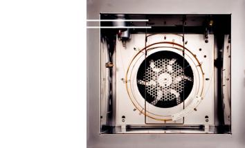
To Install a Capillary Column Hanger
WA RN ING |
Be careful! The oven may be hot enough to cause burns. If the |
|||||
oven is hot, wear heat-resistant gloves to protect your hands. |
||||||
|
||||||
|
|
|
|
|
|
|
|
Wear safety glasses to protect your eyes from flying particles |
|||||
WARNING |
||||||
while handling, cutting, or installing glass or fused silica capillary |
||||||
|
||||||
|
columns. Use care in handling these columns to prevent puncture |
|||||
|
wounds. |
|||||
|
|
|
|
|
|
|
|
1 Prepare the column and oven for maintenance. See |
|||||
|
“Preparing the GC for Maintenance” on page 15. |
|||||
|
2 Select either the front or back hanger position. (Hanger is |
|||||
|
shown in back position.) |
|||||
|
Front position |
|
|
|
|
|
|
|
|
||||
|
Back position |
|
|
|||
|
|
|||||
3Insert the ends of the hanger into the slots in the selected position.
Maintaining Your GC |
19 |
2 Maintaining Capillary Columns
To Condition a Capillary Column
1 Gather the following:
• One 7/16-inch, and 1/4-inch wrenches
• No-hole ferrule (See “Consumables and Parts for Columns” on page 18.)
• Column nut
|
= |
|
|
Do not use hydrogen as the carrier for conditioning! It could vent |
|
WA RN ING |
||
into the oven and present an explosion hazard. |
||
|
||
|
|
|
|
2 Prepare the column and oven for maintenance. See |
|
|
“Preparing the GC for Maintenance” on page 15. |
|
|
Be careful! The oven and/or detector may be hot enough to cause |
|
WARNING |
||
burns. If the detector is hot, wear gloves to protect your hands. |
||
|
||
|
|
|
|
Wear safety glasses to protect your eyes from flying particles |
|
WARNING |
||
while handling, cutting, or installing glass or fused silica capillary |
||
|
||
|
columns. Use care in handling these columns to prevent puncture |
|
|
wounds. |
|
|
|
|
|
3 Install the column into the inlet using the new ferrules. See: |
|
|
• “To Install a Capillary Column with the Split/Splitless |
|
|
Inlet” on page 36 |
|
|
• “To Install a Capillary Column with the Purged Packed |
|
|
Inlet” on page 58 |
|
|
• “To Install a Capillary Column with the COC Inlet” on |
|
|
page 90 |
|
|
• “To Install a Capillary Column with the PTV Inlet” on |
|
|
page 111 |
|
|
• “To Install a Capillary Column with the VI” on page 135 |
20 |
Maintaining Your GC |
Maintaining Capillary Columns |
2 |
4 Cap the detector column fitting.
5 Set a minimum velocity of 30 cm/s, or as recommended by the column manufacturer. Let gas flow through the column at room temperature for 15 to 30 minutes to remove air.
6 Program the oven from room temperature to the maximum temperature limit for the column. Increase the temperature at a rate of 10 to 15 °C/min. Hold at the maximum temperature for 30 minutes.
7 Prepare the GC for maintenance. See “Preparing the GC for Maintenance” on page 15.
WA RN ING |
Be careful! The oven and/or detector may be hot enough to cause |
|
burns. If the detector is hot, wear gloves to protect your hands. |
||
|
||
|
|
|
|
Wear safety glasses to protect your eyes from flying particles |
|
WARNING |
||
while handling, cutting, or installing glass or fused silica capillary |
||
|
||
|
columns. Use care in handling these columns to prevent puncture |
|
|
wounds. |
|
|
|
|
|
8 Attach the column to the detector. For details, select your |
|
|
specific detector from the following list: |
|
|
• “To Install a Capillary Column in the FID” on page 155 |
|
|
• “To Install a Capillary Column in the NPD” on page 214 |
|
|
• “To Install a Capillary Column in the TCD” on page 182 |
|
|
• “To Install a Capillary Column in the uECD” on page 198 |
|
|
• “To Install a Capillary Column Adapter in the FPD” on |
|
|
page 233 |
Maintaining Your GC |
21 |
2 Maintaining Capillary Columns
9Restore the analytical method.
•For FID or FPD, immediately turn off the flame.
•For NPD, immediately turn off the bead.
10After the GC becomes ready, wait 10 minutes, then ignite the detector flame or bead.
22 |
Maintaining Your GC |
Maintaining Capillary Columns |
2 |
To Cut a Loop from a Column
|
1 |
Gather the following: |
|
|
|
• New ferrule(s) for the column inlet connection |
|
|
|
• Column cutter |
|
|
2 |
Prepare the inlets for maintenance. See “Preparing the GC |
|
|
|
for Maintenance” on page 15. |
|
|
Be careful! The oven and/or inlet may be hot enough to cause |
||
WA RN ING |
|||
burns. If either is hot, wear heat-resistant gloves to protect your |
|||
|
|||
|
hands. |
||
|
|
||
|
Wear safety glasses to protect your eyes from flying particles |
||
WARNING |
|||
while handling, cutting, or installing glass or fused silica capillary |
|||
|
|||
|
columns. Use care in handling these columns to prevent puncture |
||
|
wounds. |
||
|
|
|
|
|
3 |
Loosen the inlet column nut and remove the column from the |
|
|
|
inlet. |
|
|
4 |
Uncoil one loop of column from the column hanger. |
|
|
5 |
Cut the unwanted loop from the column. |
|
|
6 |
Install the column into the inlet using the new ferrules. See: |
|
|
|
• “To Install a Capillary Column with the Split/Splitless |
|
|
|
Inlet” on page 36 |
|
• “To Install a Capillary Column with the Purged Packed Inlet” on page 58
• “To Install a Capillary Column with the COC Inlet” on page 90
• “To Install a Capillary Column with the PTV Inlet” on page 111
• “To Install a Capillary Column with the VI” on page 135
Maintaining Your GC |
23 |
2 Maintaining Capillary Columns
To Reverse a Column and Bakeout Contaminants
1 Gather the following:
• 1/4-inch wrench
• Column cutter
2 Prepare the GC for maintenance. See “Preparing the GC for Maintenance” on page 15.
WA RN ING |
Be careful! The oven and/or detector may be hot enough to cause |
|
burns. If the detector is hot, wear gloves to protect your hands. |
||
|
||
|
|
|
|
Wear safety glasses to protect your eyes from flying particles |
|
WARNING |
||
while handling, cutting, or installing glass or fused silica capillary |
||
|
||
|
columns. Use care in handling these columns to prevent puncture |
|
|
wounds. |
|
|
|
|
|
3 Disconnect the column from the inlet and detector. |
|
|
4 If necessary, cut a loop from the column. (See “To Cut a Loop |
|
|
from a Column” on page 23.) Do not attach the column to the |
|
|
inlet. |
|
|
5 Remove the column from the hanger and reverse its position |
|
|
(inlet and detector ends) and place the column back on the |
|
|
hanger. |
|
|
6 Attach the column to the inlet. |
|
|
Select your specific inlet from the following list: |
|
|
• “To Install a Capillary Column with the Split/Splitless |
|
|
Inlet” on page 36 |
|
|
• “To Install a Capillary Column with the Purged Packed |
|
|
Inlet” on page 58 |
|
|
• “To Install a Capillary Column with the COC Inlet” on |
|
|
page 90 |
|
|
• “To Install a Capillary Column with the PTV Inlet” on |
|
|
page 111 |
|
|
• “To Install a Capillary Column with the VI” on page 135 |
|
|
7 Attach your column to the detector. |
|
|
Select your specific detector from the following list: |
|
|
• “To Install a Capillary Column in the FID” on page 155 |
|
|
• “To Install a Capillary Column in the NPD” on page 214 |
24 |
Maintaining Your GC |
Maintaining Capillary Columns |
2 |
•“To Install a Capillary Column in the TCD” on page 182
•“To Install a Capillary Column in the uECD” on page 198
•“To Install a Capillary Column Adapter in the FPD” on page 233
8Set the column flow to the normal operating value, or set the capillary column gas velocity to 30 cm/s.
For split splitless, PTV, and VI inlets select split mode and set the split vent flow to 200 mL/min.
9Purge the column with carrier flow for at least 10 minutes before heating the oven.
10Set the inlet temperature to 300 °C or 25 °C above the normal operating temperature.
11Set the column oven 25 °C above the GC method final oven temperature to bake contaminants out of the inlet, mostly through the split vent. Do not exceed the column manufacturer’s maximum temperature limit.
12Bakeout for 30 minutes.
Maintaining Your GC |
25 |

2 Maintaining Capillary Columns
To Attach a Capillary Column Using SilTite Metal Fittings
This procedure is used to attach a capillary column to a
Microfluidic splitter or switch or an Ultimate Union.
1 Gather the following:
• SilTite ferrules (see Table 3)
• Swaging nut for SilTite ferrules (G2855-20555)
• Two 1/4-inch open-end wrenches
• One 7/16-inch open-end wrench
• Column cutting tool (5181-8836)
• Internal nut (G2855-20530)
• Lint free gloves
Table 3 Available SilTite metal ferrule packages
Part number |
SilTite ferrule description |
|
|
5188-5361 |
For 0.2- to 0.25-mm columns |
|
|
5188-5362 |
For 0.32-mm columns |
|
|
5188-5363 |
For 0.53-mm columns |
|
|
CAU TI O N |
Wear clean, lint-free gloves to prevent contamination of parts with |
|
dirt and skin oils. |
||
|
||
|
|
|
|
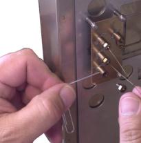
2 Pass the tubing end through the internal nut and SilTite |
|
|
ferrule leaving approximately 1 cm of fused silica tubing |
|
|
protruding beyond the ferrule. Thread the swaging nut onto |
|
|
the internal nut with the tube protruding. |
26 |
Maintaining Your GC |

Maintaining Capillary Columns |
2 |
3Using two wrenches against each other, tighten the two nuts together a little at a time, occasionally checking to see if the ferrule is gripping the tube. When the ferrule just starts to grip, notice position of the nuts and then tighten one of the nuts by turning 45 to 60 degrees of rotation, but no more than 60 degrees (one flat).
4 Remove the swaging nut.
Maintaining Your GC |
27 |

2 Maintaining Capillary Columns
5 Using a wafer column cutter, trim the tubing at the small end of the ferrule, leaving approximately 0.3 mm of tubing extending beyond the ferrule.
Check the end of the tube with a magnifier. The end of the tube need not be perfectly square, but should not have cracks that extend under the ferrule.
NO TE |
It is important that the tube end does not extend beyond 0.5 mm from the |
|
end of the ferrule. |
||
|
6Insert the assembled ferrule and nut into the SilTite fitting. Tighten with a wrench by only 15 to 20 degrees of rotation.
28 |
Maintaining Your GC |
Maintaining Capillary Columns |
2 |
To Disconnect Fused Silica Tubing From a SilTite Fitting
Loosen and remove the internal nut. If tubing and ferrule do not come free, insert a pointed object (pen, paper clip) into the ferrule release hole and press firmly. You will hear a click as the ferrule releases.
The SilTite ferrule seal should remain leak-free for many disconnections and reconnections.
Maintaining Your GC |
29 |
2 Maintaining Capillary Columns
30 |
Maintaining Your GC |
Loading...