

Page 1
Bodenkonsole BK 10, BK 11
für Wärmespeicher
WSP 2010 bis 7010, WSP 1210 F bis 4810 F,
WSP 3510 N und 5010 N, WSP 1510 S
Montageanweisung
Deutsch
Floor Console BK 10, BK 11
for Electric Storage Heaters
WSP 2010 to 7010, WSP 1210 F to 4810 F,
WSP 3510 N and 5010 N, WSP 1510 S
Installation Instructions
Socle BK 10, BK 11
pour accumulateurs de chaleur
WSP 2010 à 7010, WSP 1210 F à 4810 F,
WSP 3510 N et 5010 N, WSP 1510 S
English
Français
Notice de montage
Vloerbeugel BK 10, BK 11
voor warmteaccumulatoren
WSP 2010 tot 7010, WSP 1210 F tot 4810 F,
WSP 3510 N en 5010 N, WSP 1510 S
Montagehandleiding
Nederlands
Page 2
1
g
g
b
a
2
1
4
a
2
5
Ladung
Entladung
Ladung
Entladung
a
a
± 5mm
Bodenaufstellung
3
6
Montage bei nicht
tragfähigen Wänden
2
Page 3

1. Montageanweisung
Die Bodenkonsole (BK 10, BK 11) ermöglicht eine Aufstellung der Wärmespeicher mit einer
Bodenfreiheit von 100 mm.
Sofern eine Wandbefestigung des Wärmespeichers an einer ausreichend tragfähigen Befestigungswand möglich ist, braucht die Konsole nur unter die Standfüße des Wärmespeichers geschraubt
werden.
Ist keine Wandbefestigung möglich, z. B. bei einer Aufstellung vor einer Glaswand oder bei
einer nicht ausreichend tragfähigen Befestigungswand, sind die Konsolen mit dem Fußboden und
den Standfüßen der Wärmespeicher zu verschrauben (Abb. 6).
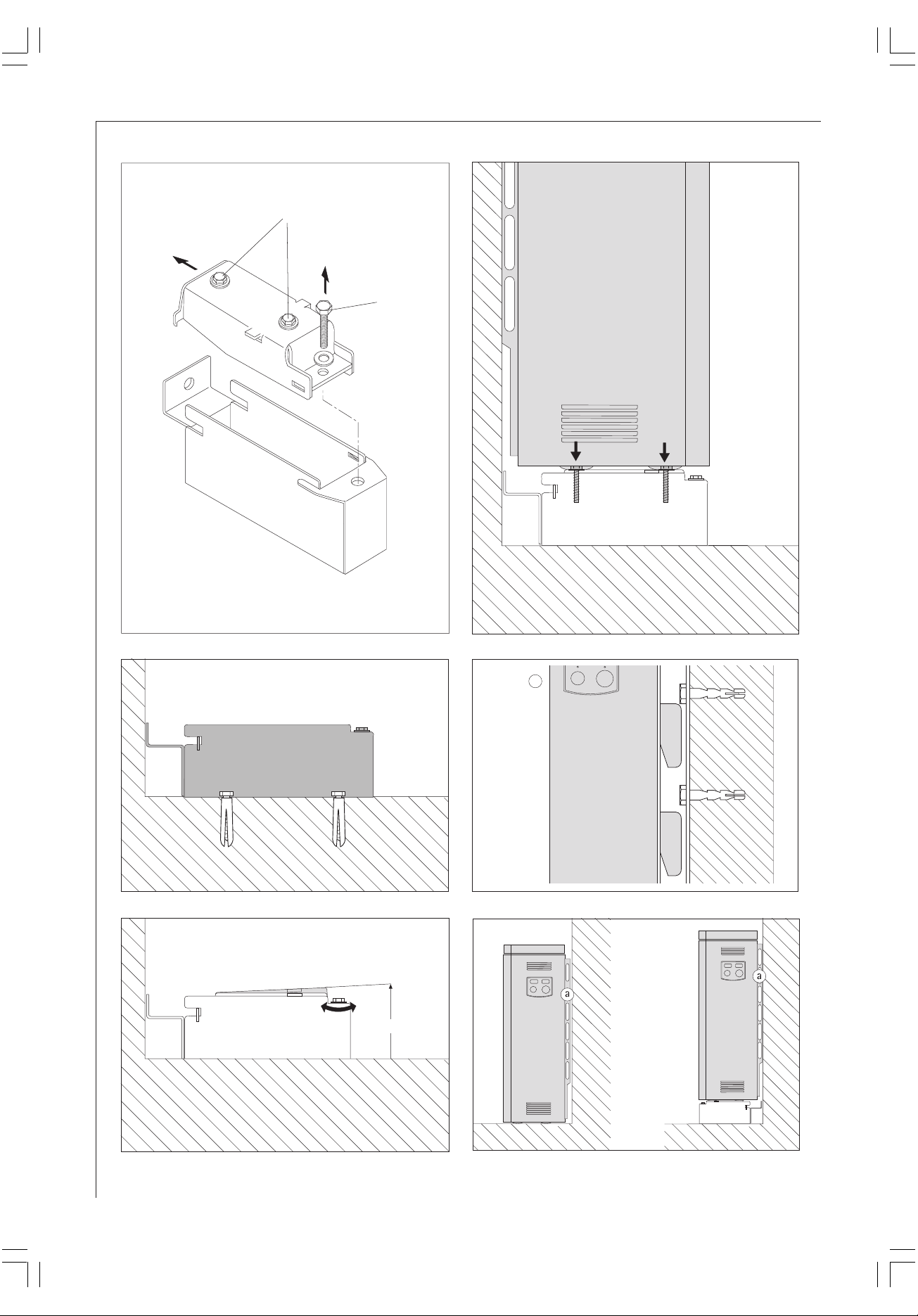
1.1 Konsolenmontage
. . . bei Wandbefestigung
• Beide Schrauben (M6 x 20) (1) aus der Konsole herausdrehen.
• Konsolen im Abstand der Wärmespeicherstandfüße (siehe Montageanweisung des Wärme-
speichers) an die Befestigungswand stellen.
• Wärmespeicher ohne Luftaus- und -eintrittgitter mit den Standfüßen auf die Konsolen
stellen.
• Gebläseschublade des Wärmespeichers herausziehen (Montageanweisung des Wärmespeichers
beachten) und den Wärmespeicher mit den Konsolen verschrauben (Abb. 4).
• Wärmespeicher über die Justierschraube (2) der Konsole mit Wasserwaage ausrichten (Abb. 3).
• Geräteaufstellung wie in der Montageanweisung des Wärmespeichers beschrieben fortsetzen.
Für den Installateur
Deutsch
. . . ohne Wandbefestigung
• Oberteil der Konsole aus dem Unterteil herausnehmen. Hierzu muss die Justierschraube (2)
herausgedreht und das Oberteil nach hinten herausgezogen werden (Abb. 1).
• Beide Schrauben (M6x20) (1) aus der Konsole herausdrehen.
• Konsolen im Abstand der Wärmespeicherstandfüße (siehe Montageanweisung des Wärmes-
peichers) an den vorgesehenen Aufstellort stellen und mit geeigneten Befestigungsmitteln mit
dem Fußboden verschrauben (Abb. 2).
• Konsolen-Oberteil wieder in das Unterteil schieben und die herausgenommene Justierschraube
(2) eindrehen (Abb. 3).
• Wärmespeicher ohne Luftaus- und -eintrittgitter mit den Standfüßen auf die Konsolen
stellen (Abb. 4).
• Gebläseschublade des Wärmespeichers herausziehen (Montageanweisung des Wärmespeichers
beachten) und den Wärmespeicher mit den Konsolen verschrauben (Abb. 4).
• Wärmespeicher über die Justierschraube (2) der Konsole mit Wasserwaage ausrichten (Abb. 3).
• Geräteaufstellung wie in der Montageanweisung des Wärmespeichers beschrieben fortsetzen.
3
Page 4

English
For the Fitter
1. Installation Instructions
The floor console (BK 10, BK 11) enables the storage heaters to be installed with a floor clearance
of 100 mm.
Insofar as the storage heater can be fixed to a sufficiently stable wall, the console only needs to be
screwed under the feet of the storage heater.
If no wall fastening is possible, e.g. when installed in front of a glass wall or if the wall to which it
is fixed does not have adequate stability, the consoles must be screwed to the floor and the feet of
the storage heaters (fig. 6).
1.1 Console Installation
. . . for wall fastening
• Unscrew both screws (M6 x 20) (1) from the console.
• Place the consoles against the wall with the space of the storage heater feet (see installation
instructions of the storage heater).
• Place the feet of the storage heaters without air outlet and inlet grilles on the consoles.
• Pull out the fan drawer of the storage heater (see the installation instructions of the storage
heater) and screw the storage heater to the consoles (fig. 4).
• Align the storage heater with the adjusting screw (2) of the console using a spirit level (fig. 3).
• Continue unit assembly as described in the installation instructions of the storage heater.
. . . without wall fastening
• Remove the top part of the console from the bottom part. To do this, the adjusting screw (2)
must be unscrewed and the top part pulled out towards the back (fig. 1).
• Unscrew both screws (M6 x 20) (1) from the console.
• Place the consoles at the distance of the storage heater feet at the planned installation point
(see installation instructions of the storage heater) and screw to the floor with suitable
fastenings (fig. 2).
• Push the console top into the bottom and screw in the removed adjusting screw (2) (fig. 3).
• Place the feet of the storage heaters without air outlet and inlet grilles on the consoles (fig. 4).
• Pull out the fan drawer of the storage heater (note the installation instructions of the storage
heater) and screw the storage heater to the consoles (fig. 4).
• Align the storage heater with the adjusting screw (2) of the console using a spirit level (fig. 3).
• Continue unit assembly as described in the installation instructions of the storage heater.
4
Page 5

EHT Haustechnik GmbH
Markenvertrieb AEG
Gutenstetter Straße 10
D-90449 Nürnberg
GERMANY
www.aeg-haustechnik.de
info@eht-haustechnik.de
Kundendienst
Tel.: +49 18 03/70 20 20
Fax: +49 18 03/70 20 25
Ersatzteilverkauf
Tel.: +49 18 03/70 20 40
Fax: +49 18 03/70 20 45
H 262 403 560
EHT-Haustechnik GmbH
248589/33249/1/7827 · WI · Technische Änderungen vorbehalten · Subject to technical modifications · Sous réserve de modifications techniques · Technische wijzigingen voorbehouden
 Loading...