

AEG Protect B.1000 BP PRO, Protect B.1800 PRO, Protect B.1000 PRO, Protect B.1400 PRO, Protect B.1800 BP PRO Operating Instructions Manual
...
OPERATING INSTRUCTIONS
EN
Protect B.PRO
Protect B. 750 PRO Protect B.1000 (BP) PRO
Protect B.1400 PRO Protect B.1800 (BP) PRO
Protect B.2300 PRO Protect B.3000 (BP) PRO

2
EN

3
EN
Thank you for purchasing the Protect B.
PRO UPS from
AEG Power Solutions.
The following safety precautions are an important part of
these operating instructions. They are designed to help you
avoid problems caused by operating errors and to protect
you against any possible hazards. Please read these
instructions carefully before using the product for the first
time!

4
EN
1 Notes on these Operating Instructions
Duty to provide information
These operating instructions are designed to help you properly
and safely install and operate the following Uninterruptible
Power Supply (UPS) systems: the Protect B.750 PRO,
Protect B.1000 PRO, Protect B.1400 PRO, Protect B.1800 PRO,
Protect B.2300
PRO or Protect B. 3000 PRO as well as the
corresponding external battery units Protect B.1000 BP
PRO,
Protect B.1800 BP
PRO and Protect B.3000 BP PRO, hereinafter
collectively referred to as PROTECT B.
PRO. This operating
instructions contain important information on avoiding hazards.
Make sure that you read through these instructions
carefully before attempting to install or operate this
device!
These operating instructions are part of the Protect B. PRO.
The operator of this device is required to make these operating
instructions openly available to any persons who transport, install
or service the Protect B.
PRO or perform any other work on this
device.
Validity
These operating instructions comply with the current technical
specifications of the Protect B.
PRO at the time of publication.
The contents do not constitute a contract and are for information
purposes only.
Warranty and liability
We reserve the right to make any changes to the information in
this operating manual, with respect to the specifications and the
operating instructions in particular, at any time.
Any goods delivered that you want to return must be returned
within eight days after the receipt of those goods, along with the
packing slip. Later claims cannot be honored.
Any damages incurred due to non-observance of these
instructions (including any damage to the warranty seal)

5
EN
invalidate any warranty claims. AEG accepts no liability for
consequential damages. AEG will rescind all obligations, such as
warranty agreements, service contracts, etc., without prior notice
in the event that any spare parts other than original AEG spare
parts or those purchased by AEG are used for maintenance and
repair.
Handling
The Protect B. PRO is designed so that all of the steps that need
to be taken for its installation and operation can be done without
having to open the device. Any maintenance or repairs are to be
performed by qualified technicians only.
Illustrations are included to make certain steps more clear and
easier to understand.
If there is any potential danger to personnel and equipment while
performing certain work, these activities are accompanied by
pictograms, whose meanings are explained in the safety
instructions in Chapter 3.
Hotline
Should you still have any questions after reading this operating
manual, please contact your retailer or our hotline:
Tel: +49 (0)180 5 234 787
Fax: +49 (0)180 5 234 789
Internet: www.aegps.com
Copyright
Any forwarding, reproduction and/or storage using electronic or
mechanic means of these operating instructions, even in part,
requires the express prior written consent of AEG.
© Copyright AEG 2012. All rights reserved.

6
EN
Table of Contents
1 Notes on these Operating Instructions ................................. 4
2 General Information ............................................................ 8
2.1 Brief overview .............................................................. 8
2.2 System description ....................................................... 9
2.3 Technical data ............................................................ 11
3 Safety Regulations ............................................................ 16
3.1 General safety precautions ........................................ 16
3.2 Safety precautions for Protect B. PRO ...................... 16
3.3 CE certificate .............................................................. 20
4 Installation ......................................................................... 21
4.1 Unpacking and checking ............................................ 21
4.2 Set-up location ........................................................... 22
4.3 Installation .................................................................. 23
4.3.1 Installation in a 19" rack ...................................... 23
4.3.2 Set-up as an upright device ( tower ) ................ 24
5 Overview: Connections, Controls and Display Components 25
5.1 Front view .................................................................. 25
5.2 Rear view ( connections ) ......................................... 26
6 Electrical Connection ........................................................ 28
6.1 Internal battery contact connection ............................ 28
6.2 External battery unit contact connection .................... 29
6.3 Mains connection ....................................................... 30
6.4 Electrical load connection .......................................... 30
7 Operation and Control ....................................................... 31
7.1 Initial commissioning .................................................. 31
7.1.1 Switching on the UPS ......................................... 31
7.1.2 Switching off the UPS ......................................... 32
7.2 Operator panel ........................................................... 33
7.2.1 Overview ............................................................. 33
7.2.2 Operating buttons ( navigation ) ........................ 33

7
EN
7.2.3 Indicators ( LED indicators ) ............................. 34
7.2.4 Liquid crystal display .......................................... 34
7.2.5 Abbreviation index ............................................. 36
7.2.6 Audible signals ................................................... 36
7.3 UPS operating states ................................................ 37
7.4 UPS settings ............................................................. 38
8 Interfaces and Communication ........................................ 40
8.1 Computer interfaces RS232 and USB ...................... 40
8.2 Communication slot .................................................. 40
8.3 Shutdown and UPS management software .............. 40
8.4 Emergency Power Off ( EPO ) ................................. 41
8.5 Overvoltage/data cable protection ............................ 42
9 Troubleshooting ............................................................... 43
9.1 Malfunctions .............................................................. 43
9.1.1 Reference fault code table ................................. 43
9.1.2 Alarm messages / warnings ............................... 44
9.1.3 Fault indications / solution approaches .............. 44
10 Service ............................................................................. 46
10.1 Charging the battery ................................................. 46
10.2 Regular checks ......................................................... 47
10.2.1 Visual check ....................................................... 47
10.2.2 Battery check ..................................................... 47
10.2.3 Fan check .......................................................... 47
10.3 Battery replacement .................................................. 48
11 Storage, Removal and Disposal ...................................... 51
11.1 Storage ...................................................................... 51
11.2 Removal .................................................................... 51
11.3 Disposal .................................................................... 51
12 Appendix .......................................................................... 53
12.1 Glossary ( technical terms ) ..................................... 53
12.2 Index ......................................................................... 54
12.3 Notes ......................................................................... 55

8
EN
2 General Information
The Protect B.PRO is an Uninterruptible Power Supply
(UPS) for important electrical loads such as personal
computers, workstations,
servers, network compo
nents, telecommunication equipment and similar
electrical loads.
The Protect B. PRO series is a compact, interactive, sinusoidaltype UPS available with output power ratings of 750, 1000, 1400,
1800, 2300 and 3000 VA.
The UPS was designed for either horizontal
/ lying operation
(rack
/ 19" with 2 U), or vertical/upright operation (tower).
2.1 Brief overview
The front of the UPS features the liquid crystal display and four
push buttons, enabling easy configuration, monitoring and
control and which display the AC mains status, information on
mains faults and the output status of the UPS. Two bar displays
for load and battery capacity indication, various status displays
(including mains
/ battery mode, for example) and for alarm
activation in case of mains failure, overload, output-side shortcircuit, discharged battery or a faulty battery system provide
considerable insight into the current operating situation.
Numerous measured values which can be shown on the display
of the UPS regarding the input
/ output, the battery and the
connected load provide further detailed information if needed.
Precise display of the remaining operating time based on the
current connected load facilitates controlled shutdown in battery
mode.
The back of the Protect B. PRO features the mains connections,
communication interfaces and connections for data cable
overvoltage protection. Manageable output sockets make
targeted load segmentation possible. Important UPS data are
monitored continuously and transferred to the computer using
the USB or RS232 interface and the CompuWatch software.
With the optional SNMP adapter, remote monitoring via an
SNMP connection and multiserver shutdowns are possible.
i

9
EN
Features of Protect B. PRO:
VI (line-interactive) protection technology
with sinusoidal output voltage
Microprocessor control for high reliability
and optimum control behaviour
Overload, short-circuit proof
Operator-friendly LCD (liquid crystal display) for easier
readability
/ configuration
State-of-the-art battery management with temperature-
compensated charging characteristics and integrated
protection against deep discharging and overcharging
Maintenance-free, sealed lead-acid battery system,
hot-swappable
Emergency Power Off contact for the immediate electronic
switch-off of connected electrical loads
Separate, manageable output circuit with IEC sockets for
load segmentation
Intelligent monitoring system with USB and RS232 inter-
faces; expansion slot for expansion cards, e.g. SNMP, can
be used at the same time
CompuWatch software for shutdown, status indications and
measured values for all common operating systems
(Windows, Mac, Linux etc.)
Compact construction
/ versatile in use thanks to its combi-
nation tower
/ rack design with rotating liquid crystal display
2.2 System description
The UPS is connected to a safety socket between the public
mains and the electrical loads to be protected. During normal
operating conditions when the Protect B.
PRO is being supplied
with mains voltage, the battery charge rectifier keeps the battery
fully charged.
Electrical loads connected to the Protect
B. PRO are supplied
with power via mains filters in this operating condition. These
filters provide effective protection against mains overvoltage
spikes and high-frequency interference.
10
EN
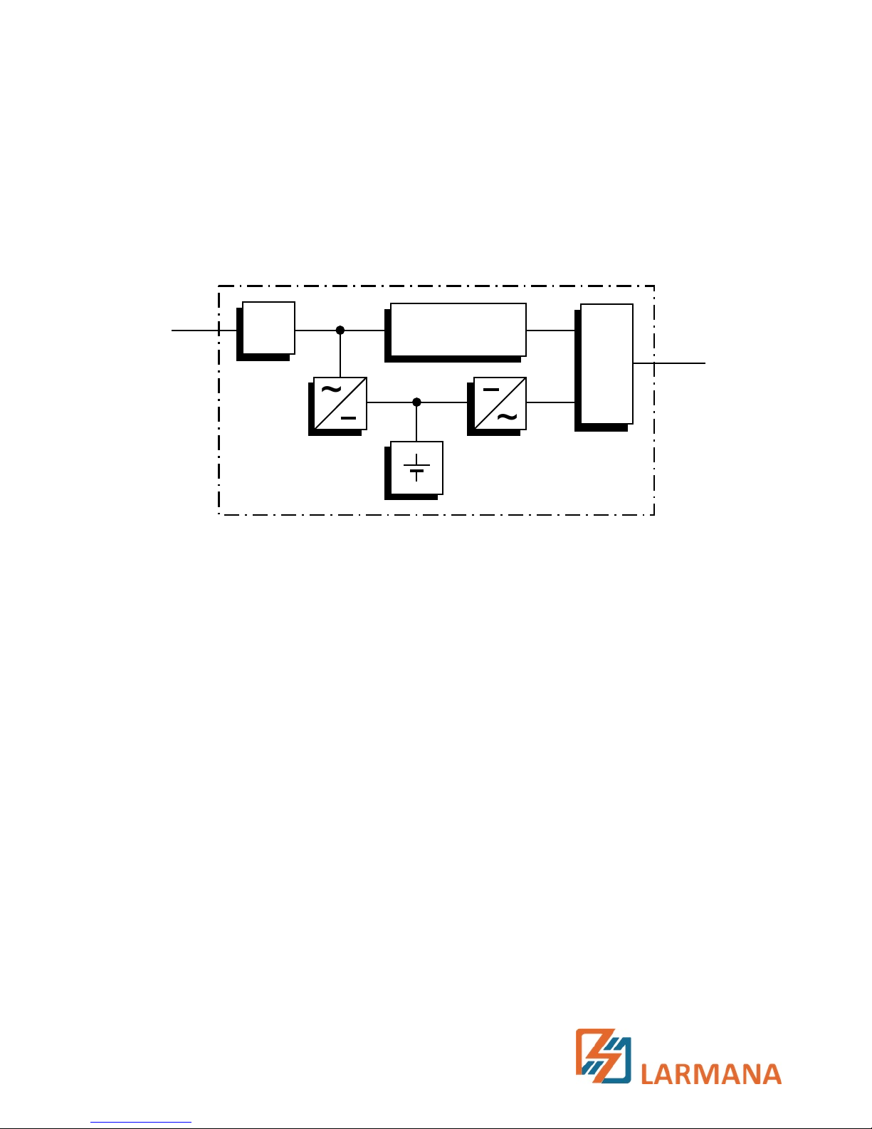
Battery
Inverter
Rectifier
Load
Mains
Mains
filter
AVR
Under continuous mains undervoltage or overvoltage within
defined ranges, the automatic voltage regulation (AVR) provides
additional stabilisation of the electrical load voltage. Voltage
fluctuations of the public mains are thus damped to a level
acceptable for the electrical loads. This occurs without accessing
the internal power reserves, which in turn has a positive effect on
battery availability.
Block diagram of UPS Protect B. PRO
If a mains failure occurs, the switch device is activated. At this
point, the inverter takes over the supply of power to the
connected electrical loads to avoid the risk of data loss or
electrical load damage. The Protect B.
PRO continues to provide
power until the battery is discharged or until your IT system is
properly shut down and switched off.
This autonomy time is largely dependent on the connected
electrical load value. When the mains supply exhibits normal
values again, the UPS switches the electrical load back to the
mains. The battery charge rectifier then recharges the battery.
If a mains failure occurs, the mains input into the device is disconnected via both poles for safety reasons (VDE, German
Association for Electrical, Electronic & Information
Technologies). This securely prevents feeding back into the
mains and live voltage on the poles of the power plug.
Additional measures also ensure effective protection of the
data/network interface.
Switch
device

11
EN
2.3 Technical data
Type rating
Protect B. 750 PRO 750 VA (cos = 0.9 lag.)
675 W
Protect B.
1000 PRO 1000 VA (cos = 0.9 lag.)
900 W
Protect B.
1400 PRO 1400 VA (cos = 0.9 lag.)
1260 W
Protect B.
1800 PRO 1800 VA (cos = 0.9 lag.)
1620 W
Protect B.
2300 PRO 2300 VA (cos = 0.9 lag.)
2070 W
Protect B.
3000 PRO 3000 VA (cos = 0.9 lag.)
2700 W
UPS input 1ph~/N/PE
Rated supply voltage 220 / 230 / 240 Vac
Voltage range without battery ±20%
Frequency (automatic detection) 50
/60 Hz ± 5 Hz
Current consumption at 230 Vac, full load and battery charge (max.)
Protect B.
750 PRO 4.0 A
Protect B.
1000 PRO 5.4 A
Protect B.
1400 PRO 7.5 A
Protect B.
1800 PRO 9.7 A
Protect B.
2300 PRO 12.4 A
Protect B.
3000 PRO 16.1 A
Connection Plug acc. to IEC 320
UPS output
Rated output voltage 220 / 230 / 240 Vac ± 10%
(in ECO & AVR
range)
Rated output voltage
tolerance in battery mode ±3%
Frequency in battery mode 50/60
Hz ± 1 Hz
208 Vac with 20%
power reduction

12
EN
Rated output current (at 230 Vac)
Protect B.
750 PRO 3.2 A
Protect B.
1000 PRO 4.3 A
Protect B.
1400 PRO 6.1 A
Protect B.
1800 PRO 7.8 A
Protect B.
2300 PRO 10.0 A
Protect B.
3000 PRO 13.0 A
Power factor range 0.8
lag. to 0.9 cap.
with full power output
10% power reduction in the
range
of 0.5 lag. to 0.8 lag.
Transfer time in case of mains failure 2-
6 ms (typical), 8 ms max.
Voltage waveform Sinusoidal, distortion
<
5% THD (linear load)
<
10% THD (non-linear load)
Connection sockets acc. to IEC 320
Overload capacity in mains mode
120% for 5 min
>
120% – 150% for 10 s
>
150% for 1 s
in battery mode
110% for 1 min
>
110% – 150% for 10 s
>
150% – 200% for 500 ms
>
200% for 150 ms
Battery
Coupled
battery
modules
Autonomy times (rated load, cos
= 0.9 lag.)
with 100% charged battery and at 25 °C
750 VA 1000 VA 1400 VA 1800 VA 2300 VA 3000 VA
with integrated
battery system
3.5
min. 3.5 min. 5 min. 4.5 min.
3.5 min.
4 min.
with 1 ancillary
battery unit
- - - 14 min. - - - 17.5 min. - - - 15 min.
Temperature-dependent
charging voltage Yes
Deep discharge protection
/
Protection against overcharging Yes

13
EN
Rated direct current (intermediate circuit)
Protect B.
750 PRO 24 V
Protect B.
1000 PRO 24 V
Protect B.
1400 PRO 48 V
Protect B.
1800 PRO 48 V
Protect B.
2300 PRO 72 V
Protect B.
3000 PRO 72 V
Trickle charge voltage 2.28 Vdc/cell (25 °C preset)
Reduction 0.3Vdc/cell at >35°C)
Battery charge current 1.2 Adc max.
Battery type Sealed lead-acid battery (VRLA)
branded product
Protect B.
750 PRO 2 blocks of 12 V 7 Ah each
Protect B.
1000 PRO 2 blocks of 12 V 8.5 Ah each
Protect B.
1000 BP PRO 2 banks / 2 blocks of 12V 8.5Ah each
Protect B.
1400 PRO 4 blocks of 12 V 7 Ah each
Protect B.
1800 PRO 4 blocks of 12 V 8.5 Ah each
Protect B.
1800 BP PRO 2 banks / 4 blocks of 12V 8.5Ah each
Protect B.
2300 PRO 6 blocks of 12 V 7 Ah each
Protect B.
3000 PRO 6 blocks of 12 V 8.5 Ah each
Protect B.
3000 BP PRO 2 banks / 6 blocks of 12V 8.5Ah each
Recharge times ~
8h to 90% with internal battery
~
24h to 90% with battery expansion
Communication
Interfaces RS232 (SUB-D (9-pole)), USB
Additionally: Communication slot
for expansions (e.g. relay card /
SNMP mini etc.)
Remote switch-off contact Floating (NC contact)
Shutdown software on CD "CompuWatch" for all common
operating systems, e.g. Windows,
Linux, Mac, Unix, Novell, Sun
General data
Classification VI SS 211 acc. to IEC 62040 - 3
Line-interactive technology

14
EN
Efficiency B. 750 PRO > 97% / > 90% / > 83%
with a 50-100% load B.
1000 PRO > 97% / > 90% / > 83%
(ECO / AVR / battery mode) B.
1400 PRO > 97% / > 90% / > 85%
B.
1800 PRO > 97% / > 90% / > 85%
B.
2300 PRO > 97% / > 90% / > 87%
B.
3000 PRO > 97% / > 90% / > 87%
Inherent noise (at 1m distance)
Protect B.750
- B.3000 40 dB(A) in mains mode (ECO)
and load < 70%
Protect B.750
- B.1800 45 dB(A) in mains mode and
Protect B.2300
- B.3000 55 dB(A) load > 70%
Protect B.750
- B.1000 45 dB(A)
Protect B.1400
- B.3000 55 dB(A)
Cooling type External cooling via variable speed fan
Operating temperature range 0
°C to +40 °C
Recommended: +15
°C to +25 °C
(depends on battery system)
Storage temperature range -20
°C to +50 °C
Humidity
90% (without condensation)
Set-up altitude Up to 1,000
m at rated power
Up to 2,000
m with 10% power
Up to 3,000
m with 20% reduct.
Max.
transport altitude: 10,000 m
Connections
Mains connection IEC320 C14 (B.750-B.1800)
IEC320 C20 (B.2300-B.3000)
Electrical load connections
Protect B.750
- B.1800 4 x IEC320 C13 (UPS-direct)
4 x IEC320 C13 (manageable)
Protect B.2300
- B.3000 3 x IEC320 C13 (UPS-direct)
1 x IEC320 C19 (UPS-direct)
3 x IEC320 C13 (manageable)
Display Liquid crystal display
Additional 3 LEDs for operating display
Housing colour Blackline, silver front
in battery mode

15
EN
Weight (net/gross)
Protect B.
750 PRO 14.6 kg / 18.0 kg
Protect B.
1000 PRO 15.1 kg / 18.5 kg
Protect B.
1000 BP PRO 15.9 kg / 19.1 kg
Protect B.
1400 PRO 23.8 kg / 27.3 kg
Protect B.
1800 PRO 24.9 kg / 28.4 kg
Protect B.
1800 BP PRO 26.4 kg / 29.6 kg
Protect B.
2300 PRO 29.0 kg / 33.4 kg
Protect B.
3000 PRO 29.5 kg / 33.9 kg
Protect B.
3000 BP PRO 38.8 kg / 42.0 kg
Dimensions (W
x D x H – net)
(Specifications include front panel from horizontal viewpoint)
B.
750 PRO / B.1000 (BP) PRO 445 mm x 420 mm x 88 mm
B.
1400 PRO / B.1800 (BP) PRO 445 mm x 520 mm x 88 mm
B.
2300 PRO / B. 3000 (BP) PRO 445 mm x 640 mm x 88 mm
Together with the mounting brackets, a standardized rack installation
dimension of 19"
= 482.6 mm in exhibited. Height of the drawer: 2 U.
Dimensions (W
x D x H – gross (incl. packing materials))
B.
750 PRO / B.1000 (BP) PRO 606 mm x 505 mm x 245 mm
B.
1400 PRO / B.1800 (BP) PRO 706 mm x 572 mm x 245 mm
B.
2300 PRO / B. 3000 (BP) PRO 765 mm x 607 mm x 245 mm
Guidelines
The Protect B. PRO complies with product standard EN 62040.
The CE mark on the device confirms compliance with EC Low-
Voltage Directive 2006/95/EC and EMC Directive 2004/108/EC
for electromagnetic compatibility if the installation instructions in
the operating instructions are followed.
For 2006/95/EC Low-Voltage Directive
Reference no. EN 62040-1-1: 2003
For 2004/108/EC EMC Directive
Reference no. EN 62040-2: 2006
EN 61000-3-2: 2006 + A1: 2009 + A2: 2009
EN 61000-3-3: 2008
WARNING:
This is a category C2- UPS product. In a domestic
environment, this product may cause radio
interference, in which case the user may be
required to take additional measures.
i
16
EN
3 Safety Regulations
3.1 General safety precautions
Read these operating instructions before commissioning the
USV Protect B.
PRO for the first time and comply with the safety
precautions!
The device may only be used in technically fault-free condition,
as intended and in a safety-conscious manner in compliance
with the operating instructions! Eliminate malfunctions
immediately if they could potentially compromise safety.
The following pictograms for danger and important information
are used in these instructions:
Danger!
In case of danger to life and limb of the operator.
Attention!
In case of risk of injury or danger to the device and
device parts.
Information!
Useful and important information on the
operation
of the UPS.
3.2 Safety precautions for Protect B. PRO
This chapter contains important instructions for the UPS
Protect B.
PRO which must be followed during installation,
operation and servicing of the uninterruptible power supply and
the batteries.
The UPS is energised with voltage which is
potentially dangerous. The device may only be
opened by
trained professional personnel. Re
-
pairs may
only be made by qualified customer ser
-
vice
employees!
i
17
EN
The output can be energised even if the UPS is not
connected to the mains supply, as the UPS has its
own internal power supply (battery)!
For reasons of personal protection, the device must
be
properly earthed!
The Protect B. PRO may only be connected to 220 / 230 / 240 V
AC mains with protective earthing with a VDE-tested mains
connection cable with protective earthing conductor (included in
the scope of supply).
Risk of burns!
The battery exhibits high short-circuit currents.
Incorrect connection or errors made while
disconnecting can cause the melting of plug
connections, flying sparks and severe burns!
The device is equipped with a warning signal that is
emitted if the battery power of the P
rotect B.
PRO
has run out or if the UPS is not operating in its
normal con
dition.
For continuous operating safety and safe working
with the UPS, heed the following safety precautions:
Do not take the UPS apart!
(The UPS does not contain any parts which require regular
servicing. If you open the device, the warranty will become
null and void!)
Do not set up the device in direct sunlight or near heat
sources!
The device was intended to be set up in heated indoor
rooms. Do not set up the UPS near water or in overly humid
environments!
 Loading...