

Page 1

85.0812.00, 2003 FB-1
Floor Boxes and Power Supplies Overview
This section provides information useful for servicing, adjusting, and maintaining floor boxes and
related assemblies. Additional information presented includes flow diagrams, exploded drawings
of the floor box components with service parts references, and troubleshooting detail.
Page 2
85.0812.00, 2003 FB-2
Floor Boxes and Power Supplies Floor Boxes
1091QM5*
12V 1/2W
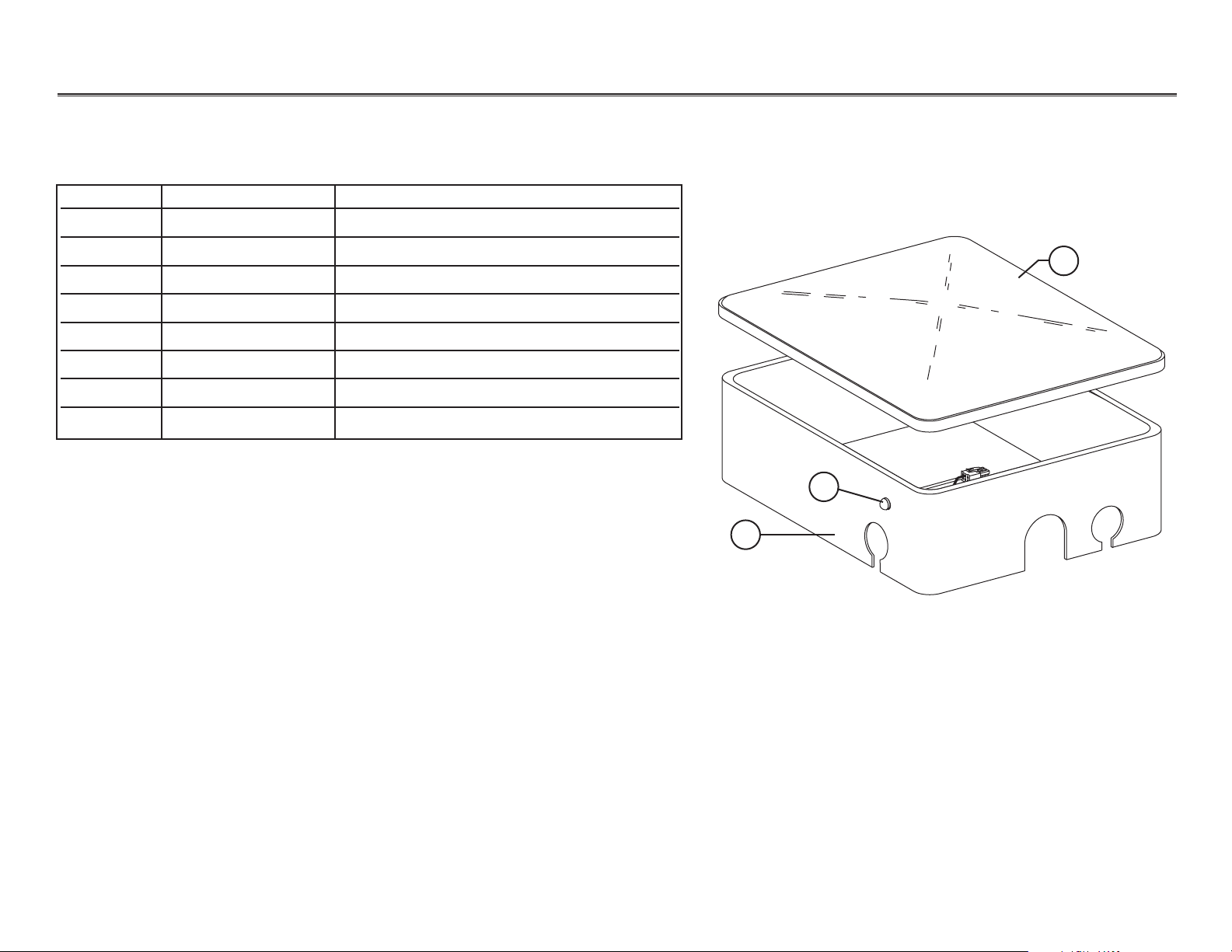
Stainless Steel Floor Box with Indicator Light
Item # Part Number Description
1 30.0380.01 Cover, small stainless steel floor box
41.0407.00 Cover, medium stainless steel floor box
41.0413.00 Cover, large stainless steel floor box
2 41.0034.00 Frame with cover and mounting kit
41.0408.00 Frame with plugs
41.0414.00 Frame
3 041.582.00 Indicator light (beginning 8/98)
— 47.1260.00 Indicator light assembly (before 8/98)
1
3
2
Stainless Steel Floor Box
(Large stainless steel
floor box shown)
*
5
M
Q
1
9
W
0
/2
1
1
V
2
1
I
D
I
Page 3
85.0812.00, 2003 FB-3
Floor Boxes and Power Supplies Floor Boxes
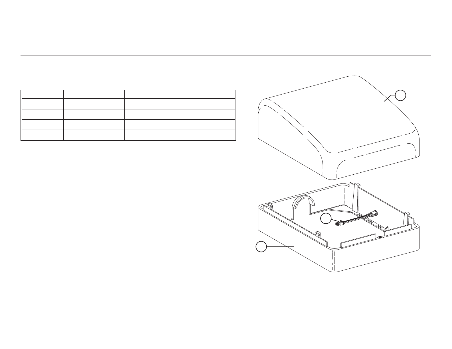
Cascade Contoured Floor Box with Indicator Light
Item # Part number Description
1 41.0416.00 Cover
2 41.0417.00 Frame
47.1256.00 Frame, International, dual hole
3 47.1260.00 Indicator light assembly
1
3
2
Cascade Contoured Floor Box
Page 4
85.0812.00, 2003 FB-4
Floor Boxes and Power Supplies Floor Boxes
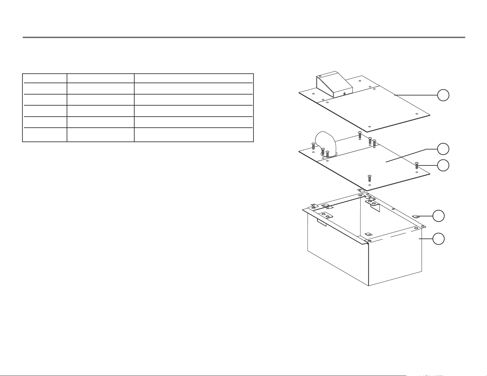
Cascade Contoured Floor Box with
1-3/4" and 2" Umbilical Elbow Assembly
Item # Part Number Description
1 41.1413.00 Cover with 2" umbilical connector
2 41.1179.00 Cover with 1-3/4" umbilical elbow
3 001.202.01 Screws pkg 8
4 006.122.01 Retainer nut pkg 8
5 41.1173.00 Flush-mount box
Flush-Mount Floor Box
1
5
2
3
4
Page 5
85.0812.00, 2003 FB-5
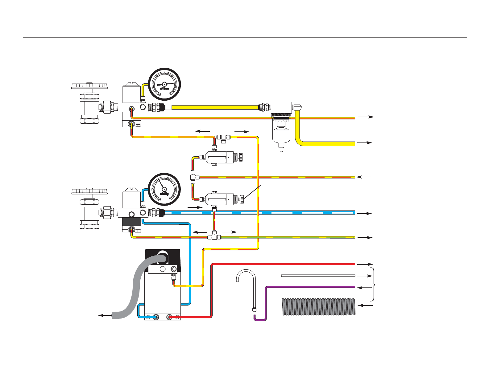
Floor Boxes and Power Supplies Plumbing Diagram
10
20
30
40
50
60
70
80
90
100
psi
kg/cm
10
20
30
40
50
60
70
80
90
100
psi
kg/cm
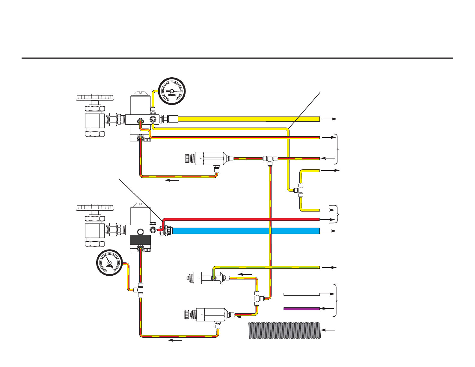
Radius only — cuspidor and
Assistant’s syringe
Air manual
shut-off valve
Radius only —
delivery system
Post box or foot control
Post box or control head
(to master On/Off toggle)
Floor box
Post box
Self-contained water/ cuspidor
(Cascade and Radius)
Miscellaneous —
for accessories
(Cascade and Radius)
Water manual
shut-off valve
Air filter/regulator assembly (white body)
80 psi air regulator (replace as a complete assembly)
Water filter/regulator
assembly (black body)
40 psi regulator
(pre-set, replace
as a complete
assembly)
Water pre-regulator.
Must be set at
40 psi
(replace as a
complete assembly)
Floor box
After November 1999
NOTE: This line is only connected with
the Radius system.
NOTE: This line is only connected if
the Radius cuspidor or
Asst’s is installed, w/out the
Radius delivery system.
Vacuum and/or gravity drain
(80 psi)
(40 psi)
(40 psi)
(40 psi)
(80 psi)
(80 psi)
3 4
50
40
60
2
1
5
30
70
20
80
6
90
10
100
0
psi
2
7
0
kg/cm
3 4
50
40
60
2
1
5
30
70
20
80
6
90
10
100
0
psi
2
7
0
kg/cm
Page 6
85.0812.00, 2003 FB-6
Floor Boxes and Power Supplies Plumbing Diagram
10
20
30
40
50
60
70
80
90
100
psi
kg/cm
10
20
30
40
50
60
70
80
90
100
psi
kg/cm
Air manual
shut-off valve
Post box or foot control
Post box or control head
(to master On/Off toggle)
Floor box
Post box
Self-contained water and
cuspidor (if included)
Water manual
shut-off valve
Air filter/regulator
assembly
(white body)
80 psi air regulator
(replace complete
assembly)
Water filter/regulator
assembly
(black body)
(pre-set, replace complete
assembly)
Floor box
Vacuum drain
Before December 1999
Post box or control head
(from master On/Off toggle)
Post box and control head
Miscellaneous
Circulating
syringe
drip line
Water heater
Electrical outlet
Moisture separator
(80 psi)
(40 psi)
(40 psi)
(Cascade and Radius)
3 4
50
40
60
2
30
20
1
10
0
5
70
80
6
90
100
0
psi
2
7
kg/cm
3 4
50
40
60
2
30
20
1
10
0
5
70
80
6
90
100
0
psi
2
7
kg/cm
Page 7
85.0812.00, 2003 FB-7
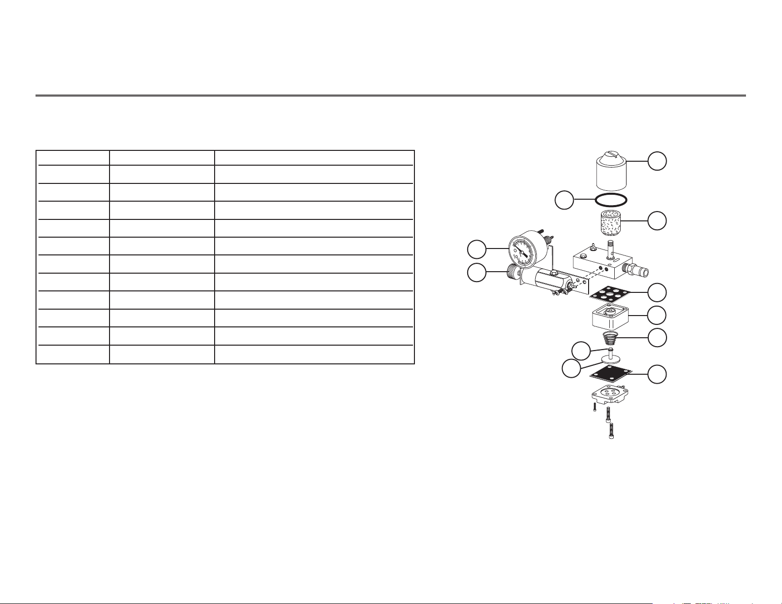
Floor Boxes and Power Supplies Regulators
Item # Part number Description
1 24.0229.00 Filter housing
2 030.019.03 O-ring pkg 10
3 24.0234.01 Filter element pkg 6
4 026.118.00 Panel mount gauge kit (0-100 psi)
5 24.0182.02 Pre-regulator, 80 psi, relieving
6 24.0137.01 9-hole gasket pkg 10
7 24.0135.00 Air filter/regulator body, White
8 22.0460.00 Spring, conical
9 030.003.02 O-ring pkg 10
10 24.0132.00 Piston with o-ring
11 22.0440.02 Diaphragm pkg 10
Air Filter/ Regulator Assembly
Air Filter/Regulator Assembly
1
2
4
5
3
6
7
8
9
11
NOTE:To increase air pressure, turn the pre-regulator knob clockwise
while reading the air pressure gauge. To decrease, turn the knob
counterclockwise. See Adjusting Regulators for more details.
10
Page 8
85.0812.00, 2003 FB-8
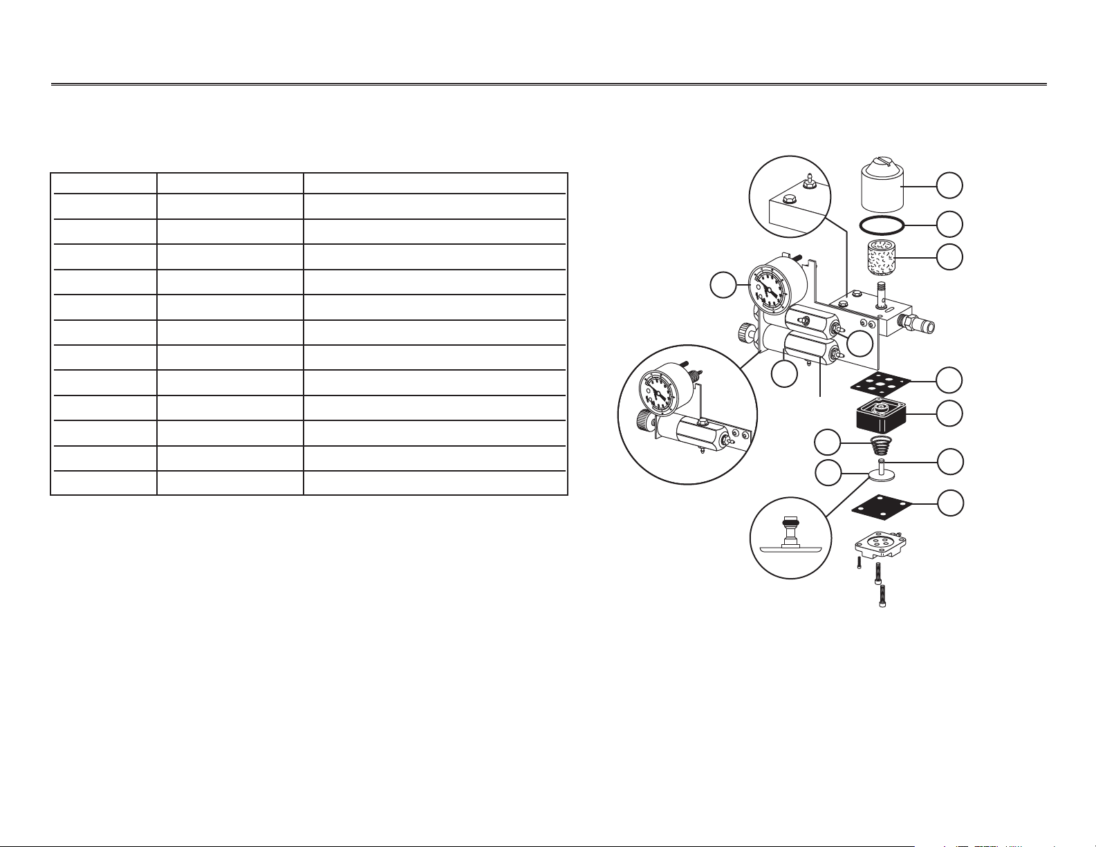
Floor Boxes and Power Supplies Regulators
Item # Part number Description
1 24.0229.00 Filter housing
2 030.019.03 O-ring pkg 10
3 24.0234.01 Filter element pkg 6
4 026.118.00 Panel mount gauge kit, 0—100 psi
5 24.0388.02 Regulator, 40 psi, relieving
6 24.0182.02 Pre-regulator, 80 psi, relieving
7 24.0137.01 Gasket, 9-hole, pkg 10
8 24.0355.00 Water filter/regulator body (black)
9 013.032.00 Spring, conical
10 24.0132.00 Piston with o-ring
11 030.003.02 O-ring pkg 10
12 22.0440.02 Diaphragm pkg 10
Water Filter/ Regulator Assembly
Water Filter/Regulator Assembly
5
6
4
1
2
3
7
8
9
11
10
12
Before 12/99
Must be set
to 40 psi
NOTE:To increase water pressure, turn the pre-regulator knob clockwise
while reading the water pressure gauge. To decrease, turn the knob
counterclockwise. See Adjusting Regulators for more details.
Before 12/99
Page 9

85.0812.00, 2003 FB-9
Floor Boxes and Power Supplies Adjustments
The air and water pre-regulators are located in the floor box. Before making adjustments, verify that the
air compressor is ON, and that it maintains 125 psi.
If the air pressure is lower than 80 psi, refer to the compressor instructions. Some compressors, especially
older ones, produce a maximum of 60-80 psi. Adjustments on this type of compressor should be done
when air pressure is near or reaches maximum psi. A-dec systems will usually function in this pressure
range, although at a reduced performance.
Adjusting
Regulators
Task Description
1Be sure manual shutoff valves are fully open (turned counterclockwise).
2Turn the system ON and check pressures.
• Air pressure should be 70 - 80 psi.
•Water pressure should be 35 - 40 psi.
3 Operate the syringe.
4Watch the gauges for a drop in pressure. In units manufactured before December 1999, replace the
filters if:
• Air pressure drops by more than 15 psi.
•Water pressure drops by more than 10 psi.
5Adjust the air or water pressure as required by turning the pre-regulator knob:
• Clockwise to increase pressure.
• Counterclockwise to decrease pressure.
NOTE: The gauge will not indicate a change in pressure when decreasing system air or water pressure,
until pressure from the system is relieved. Activate the syringe for a few seconds and check the
gauge. Repeat this process each time a decrease adjustment is made.
Page 10
85.0812.00, 2003 FB-10
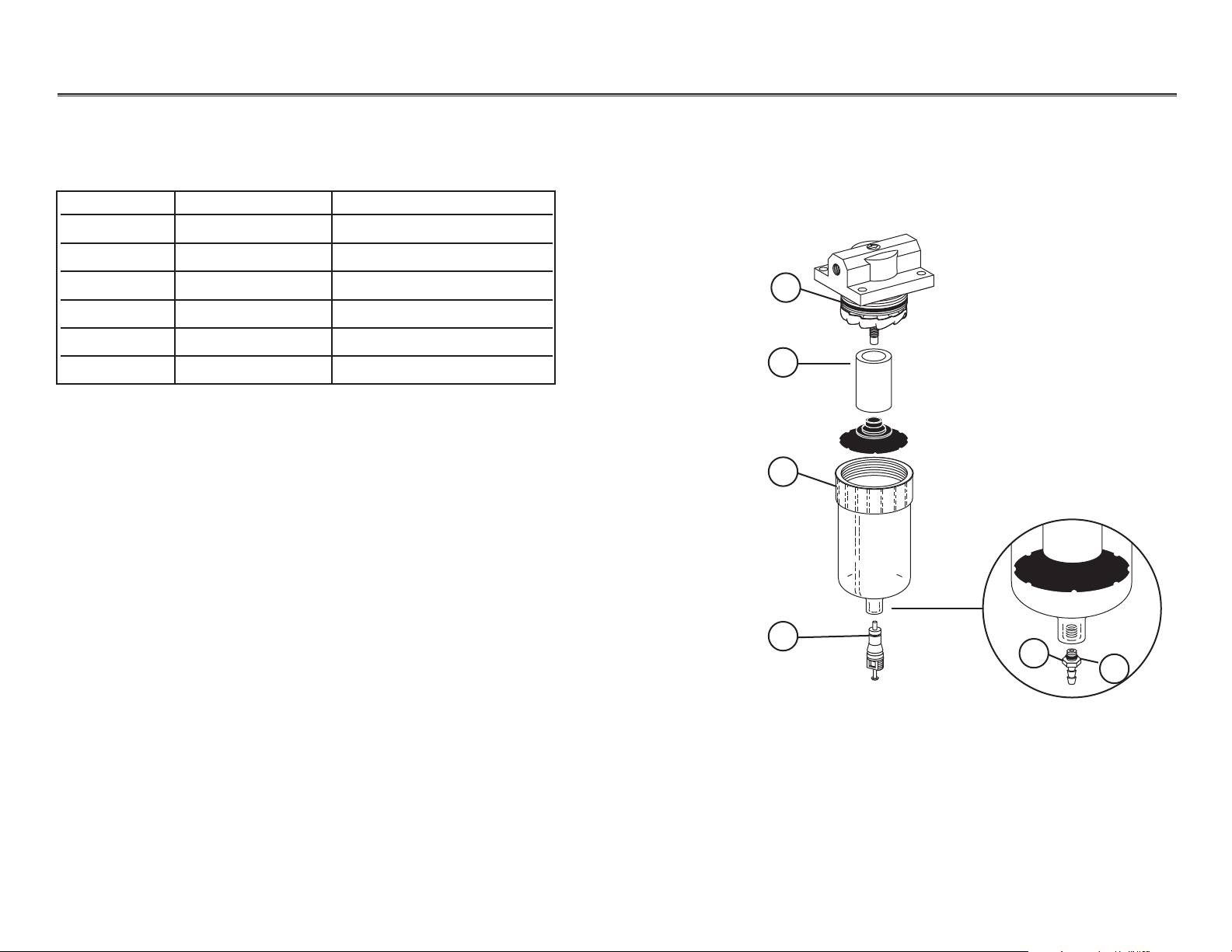
Floor Boxes and Power Supplies Moisture Separators
Item # Part number Description
1 030.023.02 O-ring pkg 10
2 97.0280.02 Filter element pkg 6
3 97.0290.00 Bowl assembly
4 026.033.01 Valve core, short pkg 10
5 023.066.00 Barb, 1/8"
6 035.026.01 O-ring special pkg 10
Manual Moisture Separator
Manual Moisture Separator
6
1
2
3
4
5
Page 11

85.0812.00, 2003 FB-11
Floor Boxes and Power Supplies Moisture Separators
90.1027.03 Automatic Moisture Separator
Automatic Moisture Separator
Item # Part number Description
1 97.0290.00 Bowl assembly with seal
1
R
Page 12

Floor Boxes and Power Supplies Troubleshooting
Problem
Action
Unit air pressure drops when
unit is in use
Check for a plugged filter element in air filter/regulator following these steps:
Task Description
1Flip the master On/Off toggle to the ON position and remove the floor box cover.
2 Locate and observe the air pressure gauge in the
floor box and press the syringe air button. If the
air pressure drops by more than 15 psi, the air filter
is clogged.
3 Inspect the element.
•With the master On/Off toggle in the OFF
position, close the air manual shutoff valve.
Bleed the system of air and water pressure.
•Remove the air regulator filter housing from
the regulator assembly.
• Remove the filter element and discard it.
4 Replace the element (beveled edge of filter faces
the manifold).
Replacing the Filter Element
Housing
Filter
(Beveled edge)
Troubleshooting information for floor boxes is listed in the following charts.
CAUTION
When replacing a filter element, be sure to install the new
filter with the beveled side towards the manifold. The unit
may not work properly if the filter is installed incorrectly.
Troubleshooting
Floor Boxes
FB-1285.0812.00, 2003
1
0
2
10
20
0
30
40
3
50
kg/cm
psi
100
60
2
7
4
90
70
80
5
6
Page 13

85.0812.00, 2003
Floor Boxes and Power Supplies Troubleshooting
Problem
Action
Low unit water pressure
Check for a plugged filter element in the water filter/regulator assembly, or a plugged water filter
screen in the manual shutoff valve (used before November 1999).
Task Description
1Flip the master On/Off toggle to the ON position and then remove the floor box cover.
2 Locate and observe the water pressure gauge in the floor box and press the syringe water button.
If the water pressure gauge drops by more than 10 psi, the water filter element and/or the water
filter screens are clogged and must be replaced.
3 Replace the water filter element.
•With the master On/Off toggle in the OFF
position, close the water manual shutoff
valve. Bleed the system of air and water
pressure.
• Remove the water regulator filter housing.
• Replace filter and reinstall the filter housing.
4Inspect the water filter screen.
•With the master On/Off toggle in the OFF
position, close the manual shutoff valves.
Bleed the system of air and water pressure.
• Loosen the compression nut and remove the water filter regulator assembly.
•Remove the filter screen and discard it.
• Reinstall the water filter regulator assembly and tighten the compression nut.
5 Open the water manual shutoff valve and flip the master On/Off toggle to the ON position.
Check the fitting for leaks.
Replacing the Water Filter Screen
Filter screen
Compression nut
FB-13
1
0
2
10
20
0
30
40
3
50
kg/cm
psi
100
60
2
4
90
7
70
80
5
6
Page 14

85.0812.00, 2003 FB-14
Floor Boxes and Power Supplies Power Supplies
A
M
A
M
May 1998 — May 1999
After May 1999
NOTE: There are no serviceable parts on A-dec power supplies. Replacement of the
complete assembly is required.
Replacing 300-Watt Power Supplies
Item # Part number Description
1 28.1434.00 100 VAC
2 28.1435.00 110-120 VAC
28.1436.00 220-240 VAC
1
This section provides information to assist in troubleshooting, replacing and
making adjustments to A-dec power supplies. Flow diagrams illustrate how
to connect power supplies to the unit after testing or replacement. These
diagrams cover all of the A-dec power supplies, except the 80-watt power
supply, which is covered in the Performer (PR) section.
10
A
M
P
1
0
A
M
P
Page 15

85.0812.00, 2003 FB-15
Floor Boxes and Power Supplies Power Supplies
300-Watt Power Supply Cable
Item # Description
1 Auxiliary cable (4 pin, Black connector)
2Handpiece control cable (6-pin, Black connector)
3 Dental light cable (6-pin, Red connector)
4Indicator light cable (6-pin, White connector)
A
M
A
M
Cable Connections to the 300-Watt Power Supply
1
2
3
4
1
0
A
M
P
1
0
A
M
P
Page 16

85.0812.00, 2003 FB-16
Floor Boxes and Power Supplies Power Supplies
300-Watt Connector/Pin Locations
A
M
A
M
Connector/Pin Locations on
the 300-Watt Power Supply
Wire side
(power supply)
Pin Voltage Wire
10 VA CBlack/White
(switched)
46 VACRed
3 24 VAC Gray
Front view
(test voltages)
Wire side
(power supply)
Black 4-Pin Connector
(Auxiliary Cable)
Black 6-Pin Connector
(Handpiece Control)
Front view
(test voltages)
Pin Voltage Wire
1Ground Green/Yellow
20 VA CBlack/White
30 VA CBlack/White
46 VACRed
5 17 VAC Violet
6 24 VAC Gray
0 24
v~
3
12
4
1
45
2
3
6
1
45
2
3
6
1
45
10
A
M
P
2
3
6
10
A
M
P
Page 17

85.0812.00, 2003 FB-17
Floor Boxes and Power Supplies Power Supplies
300-Watt Connector/Pin Locations
A
M
A
M
Connector/Pin Locations on
the 300-Watt Power Supply
Red 6-Pin Connector
(Dental Light)
Front view
(test voltages)
Wire side
(power supply)
White 6-Pin Connector
(Indicator Light)
Front view
(test voltages)
Wire side
(power supply)
Pin Voltage Wire
1Ground Green/Yellow
20 VA CBlack/White
3 15 VAC Green
4 16 VAC Blue
5 17 VAC Violet
6 10.8/12.1 VAC White
Pin Voltage Wire
1Ground Green/Yellow
20 VACBlack
3 10.8/12.1 VAC White
4 10.8 VAC Orange
5 12.1 VAC Yellow
6 12.1 VAC Yellow
0 24
v~
3
12
4
1
45
2
3
6
1
45
2
3
6
1
45
10
A
M
P
2
3
6
10
A
M
P
Page 18

85.0812.00, 2003 FB-18
Floor Boxes and Power Supplies Flow Diagram
120 Volt Before May 1998
Fuse Slot Part Number Description
F1/F3 044.164.00 12A, 250V, fast blow
F2/F4 044.167.00 3.2A, 250V, time delay
F5 NA Optional fuse
F7/F8 044.166.00 5A, 250V, fast blow
F6 046.100.00 5A, 250V, time delay
F9/F10 044.165.00 10A, 32V, time delay
0 Volts
15 Volts
16 Volts
17 Volts
Ground
0 Volts
6 Volts
Ground
17 Volts
0 Volts
0 Volts
6 Volts
24 Volts
24 Volts
Ground
24 Volts
17 Volts
To light
To A-dec accessories
To control head
Transformer
Printed circuit board
From electrical outlet
From master
On/Off toggle
Secondary wiring
Primary
wiring
Air-electric switch
(044.170.00, replace as a
complete assembly)
300-Watt Power Supply
BLK
BRN
RED
WHI
Page 19

85.0812.00, 2003 FB-19
Floor Boxes and Power Supplies Flow Diagram
Fuse Slot Part Number Description
F1/F3 044.166.00 5A, 250V, fast blow
F2/F4 044.168.00 1.6A, 250V, time delay
F5 NA Optional fuse
F7/F8 044.166.00 5A, 250V, fast blow
F6 046.100.00 5A, 250V, time delay
F9/F10 044.165.00 10A, 32V, time delay
0 Volts
15 Volts
16 Volts
17 Volts
Ground
0 Volts
6 Volts
Ground
17 Volts
0 Volts
0 Volts
6 Volts
24 Volts
24 Volts
Ground
24 Volts
17 Volts
To light
24 Volts
To A-dec
accessories
To control head
Transformer
From master
On/Off toggle
Secondary wiring
Primary wiring
Printed circuit board
From electrical outlet
240 Volt Before May 1998
Indicator light
Air-electric switches
(044.170.00, replace as
a complete assembly)
300-Watt Power Supply
Page 20

85.0812.00, 2003 FB-20
Floor Boxes and Power Supplies Flow Diagram
300-Watt Power Supply
NOTE: F6 Fuse (violet wire) variations before May 1998
NOTE: F6 fuse (violet wire) position is different compared to
later versions of circuit boards.
0 Volts
15 Volts
16 Volts
17 Volts
Ground
0 Volts
6 Volts
Ground
24 Volts
0 Volts
0 Volts
0 Volts
24 Volts
24 Volts
Ground
24 Volts
17 Volts
To light
24 Volts
To A-dec
accessories
To control head
Transformer (thermal limiter on
120V versions only)
Printed Circuit Board
Indicator Light
(for 240 versions only)
0 Volts
15 Volts
16 Volts
17 Volts
Ground
0 Volts
0 Volts
6 Volts
24 Volts
24 Volts
Ground
24 Volts
17 Volts
To light
To control
head
Printed circuit board
Transformer (thermal limiter on
120V versions only)
Indicator light
(for 240 versions only)
Fuse Slot Part # Description
F5 NA Optional fuse
F7/F8 044.166.00 5A, 250V,
fast blow
F6 046.100.00 5A, 250V
time delay
F9/F10 044.165.00 10A, 32V,
time delay
Fuse Slot Part # Description
F5 NA Optional fuse
F6/F8 044.166.00 5A, 250V,
fast blow
F6 046.100.00 5A, 250V
time delay
F9/F10 044.165.00 10A, 32V,
time delay
BLK
BRN
RED
ORA
YEL
GRN
F8
10A TIME DELAY
INLINE HEATER
F7
10A TIME DELAY
SCALER
BLU
5A FAST BLOW
5A FAST BLOW
CONTROL
T3
HEAD
BLK
BRN
RED
ORA
YEL
GRN
BLU
VIO
DENTAL
T4
LIGHT
BLK
BRN
RED
WHI
ADEC 41-1100-00 REV —
RETURNS
INLINE
HEATER
FIBER
OPTIC
SCALER
CHASSIS
WATER
HEATER
CURING
LIGHT
RETURN
15V
16V
17V
F10
DENTAL LIGHT
F9
WATER HEATER
VIO
F6
FIBER OPTIC
F5
CURING LIGHT
Page 21

85.0812.00, 2003 FB-21
Floor Boxes and Power Supplies Power Supplies
Before June 1998
The 150-watt power supply was used on equipment built before June 1998. It is no
longer available for replacement. To convert from a 150-watt power supply to the
new 300-watt order, an adapter kit P/N 90.1012.00 and the appropriate 300-watt
power supply.
Replacing 150-Watt
Power Supplies
Fiber Optic Scaler Dental Light One Low Voltage Water Heater Curing Light Electric Handpiece
(10W) (60W) (95W) (90W) (120W) (80W)
X X X
XXX
XX X
XX X
Acceptable Accessory Combinations that Exceed 150-Watts
NOTE: These combinations are acceptable since not all
accessories are used at the same time.
Page 22

85.0812.00, 2003 FB-22
Floor Boxes and Power Supplies Flow Diagram
120 Volt Before June 1998
Rev B Rev A
Color PC Board PC Board
Black 0 Volts Same
Brown 0 Volts Same
Red 6 Volts Same
Orange 24 Volts Same
Yellow 24 Volts Same
Ground 0 Volts Same
Blue 24 Volts Same
Violet 17 Volts 24 Volts
0 Volts
15 Volts
16 Volts
17 Volts
Ground
From master
On/Off toggle
From electrical
outlet
Air-electric switch (044.170.00,
replace as a complete assembly)
To light
To control head
Transformer
Printed
Circuit
Board
Secondary wiring
Primary wiring
Accessory wiring
To accessories
To control head
Control Head and Accessory
Wiring AC Voltages
150-Watt Power Supply
Page 23

85.0812.00, 2003 FB-23
Floor Boxes and Power Supplies Flow Diagram
240 Volt Before June 1998
Accessory wiring
To
accessories
To control head
From master
On/Off toggle
Air electric switch (044.170.00,
replace as a complete assembly)
From master
On/Off
toggle
To light
To control
head
Transformer
Indicator light
Printed
circuit
board
Secondary wiring
Primary wiring
Control Head and Accessory
Wiring AC Voltages
NOTE:Refer to the Acceptable Accessory Combinations that exceed 150-watts
chart in Replacing 150-Watt Power Supplies.
150-Watt Power Supply
Rev B Rev A
Color PC Board PC Board
Black 0 Volts Same
Brown 0 Volts Same
Red 6 Volts Same
Orange 24 Volts Same
Yellow 24 Volts Same
Ground 0 Volts Same
Blue 24 Volts Same
Violet 17 Volts 24 Volts
0 Volts
15 Volts
16 Volts
17 Volts
Ground
Page 24

85.0812.00, 2003 FB-24
Floor Boxes and Power Supplies Flow Diagram
0 Volts
15 Volts
16 Volts
17 Volts
Ground
Transformer
To light
Printed circuit board
Primary wiring
Secondary wiring
From electrical outlet
120 Volt
After May 1998
Fuse Position Options
0 volt - 15, 16, 17 VAC
1 volt - 14, 15, 16 VAC
14 L
15 M
16 H
100-Watt Power Supply
Page 25

85.0812.00, 2003 FB-25
Floor Boxes and Power Supplies Flow Diagram
0 Volts
15 Volts
16 Volts
17 Volts
Ground
Transformer
To light
Printed circuit board
Primary wiring
Secondary wiring
From electrical outlet
Fuse Position Options
0 volt - 15, 16, 17 VAC
1 volt - 14, 15, 16 VAC
240 Volt
After May 1998
100-Watt Power Supply
Page 26

85.0812.00, 2003 FB-26
Floor Boxes and Power Supplies Power Supplies
100, 120, and 240 Volt
White 6-pin Connector
(Indicator Light)
25-Watt Power Supply Cables and Connectors
White
6-pin
Black
6-pin
Indicator
light cable
Control
head
100 and 110-120 VAC Power Supply
Plumbing
220-240 VAC Power Supply Plumbing
Identifying 25-Watt
Connector/Pin Locations
Pin Voltage Wire
1
20 VACBlack
3
4
5
6 12.1 VAC Gray
Black 6-pin Connector
(Delivery System)
Pin Voltage Wire
1Ground green/yellow
20 VACBlack
3
4
5
6 24 VAC Yellow
Page 27

85.0812.00, 2003 FB-27
Floor Boxes and Power Supplies Power Supply Flow Diagrams
17-Watt Power Supply
60-Watt Power Supply
To A-dec intra-oral
light source
22 Volts
return ground
(Not used)
From master
On/Off toggle
Indicator light
(for 240 version only)
Fuse holder
(order fuse
P/N 046.070.00)
Transformer
From
electrical
outlet
Air-electric
switch
(044.181.00,
replace as a
complete
assembly)
From
electrical
outlet
From
master
On/Off
toggle
To A-dec
accessories
24 Volts
return ground
(Not used)
Transformer
Transformer
240 volt
wiring
120 volt
wiring
Air-electric switch
(044.181.00, replace as a
complete assembly)
Page 28

Floor Boxes and Power Supplies Troubleshooting
Problem
Action
Power supply is not working
Follow these steps to determine the problem with the power supply.
Task Description
1Plug in power supply and check for:
• An indicator light that is ON, if present.
•Working accessories.
•Proper input line voltage (100 VAC, 110-120 VAC or 220-240 VAC).
2Measure output voltages.
• If all are correct, check for loose connections.
• If some are correct, check circuit breakers.
3 Check for a tripped circuit breaker.
4 Reset the circuit breaker.
NOTE: If the power supply is receiving line voltage and the output voltages are all 0 VAC, then an
internal protector in the transformer has been tripped. Replace the entire power supply.
5 Check pilot air tubing (at the air-electric switch) air pressure. It should have a minimum of 60
psi. If not check for kinks, pinches or leakage. Replace any damaged tubing.
6 Check that the air-electric switch works properly by listening for a clicking sound. If it isn't, the
power supply has failed. Replace the power supply.
7 Check for a failed power supply by removing the cover and visually inspecting the power
supply for any visible damage (burnt wires, broken terminal strips or burn spots).
8 Replace the power supply.
Troubleshooting
Power Supplies
Troubleshooting information for power supplies is listed in the following charts.
FB-2885.0812.00, 2003
Page 29

85.0812.00, 2003 FB-29
Floor Boxes and Power Supplies Troubleshooting
Problem
Action
Some electrical accessories are
not working
Follow these steps to check fuses for continuity and the range of AC power on the electrical outlet.
Task Description
1Check for blown fuses:
• Unplug the power supply and remove the cover.
•Locate the appropriate accessory fuse, remove it and test for continuity.
• Replace any blown fuses.
2Replace the power supply cover and plug in the power cord. Test the accessories
that weren't functioning to ensure the problem has been fixed.
3 Check for normal AC power at the electrical outlet.
• If the AC power is within the correct range, the power supply has failed. Replace the
power supply.
• If the AC power is not within the correct range, have a certified electrician correct
the problem.
Nominal Mains AC Voltage Ranges
Voltage Range
100 90-110 Volts
120 108-132 Volts
220 198-242 Volts
240 216-264 Volts
Page 30

Floor Boxes and Power Supplies Troubleshooting
Problem
Action
None of the electrical accessories
are working
Follow these steps to determine the problem when none of the electrical accessories work.
Task Description
1 Check for power at the electrical outlet. If not check the following points.
•Wall switches that may be turned off, or where appropriate, circuit breakers that may
have tripped.
•Normal AC power at the electrical outlet (see chart). If the AC power is within the correct
range, the power supply has failed. Replace the power supply. If the AC power is not
within the correct range, have a certified electrician correct the problem.
2Check for blown fuses:
• Unplug the power supply and remove the cover.
•Locate the appropriate accessory fuse, remove it and test for continuity.
•Replace any blown fuses.
3Replace the power supply cover and plug in the power cord. Test the accessories that weren't
functioning to ensure the problem has been fixed.
4 Check for a failed power supply by removing the cover and visually inspecting the power
supply for any visible damage (burnt wires, broken terminal strips or burn spots). Replace the
failed power supply.
Nominal Mains AC Voltage Ranges
Voltage Range
100 90-110 Volts
110 99-121 Volts
120 108-132 Volts
220 198-242 Volts
240 216-264 Volts
FB-3085.0812.00, 2003
Page 31

85.0812.00, 2003
Floor Boxes and Power Supplies Troubleshooting
Problem
Action
None of the electrical accessories
are working
5 Check pilot air tubing (at the air-electric switch) air pressure. It should have a minimum of 60
psi. If not, check for kinks, pinches or damage. Replace any damaged tubing.
6 Check that the air-electric switch works properly by listening for a clicking sound.
•If it isn't, replace the air-electric switch (below) by removing the power supply cover and
air switch coupling. Disconnect the failed switch and install a new one. Reinstall the
coupling and power supply cover
• If the air-electric switch is working, visually inspect the power supply by removing the
cover and look for any visible damage (burnt wires, broken terminal strips or burn
spots.) Replace failed power supply.
7Test voltages at the transformer secondary terminal strip.
•Plug in the power supply and remove the cover.
•Test for AC voltage at each wire contact on the transformer secondary terminal strip (use
only the probes of a volt-ohm meter). The specified voltage for each position is either
labeled on or below the terminal strip. The AC voltages for red, green and, violet wires
should be within 1.5 volts of the specified voltage. The AC voltages for orange, yellow,
and blue wires should be within 2.5 volts of the specified voltage.
FB-31
17-Watt Air-Electric Switch 150-Watt Air-Electric Switch 300-Watt Air-Electric Switch
Coupling
Air-electric switch
Air-electric switch
Coupling
Coupling
Air-electric switch
Replacing the Air-Electric Switch
Page 32

85.0812.00, 2003 FB-32
Floor Boxes and Power Supplies Notes
 Loading...